Longitudinal End Effects in a Linear Wave Power Generator

1
Department of Industrial Economics, Electrical and Mechanical Engineering, University West, 461 86 Trollhättan, Sweden
2
Swedish Centre for Renewable Electric Energy Conversion, Department on Engineering Sciences, Uppsala University, 751 21 Uppsala, Sweden
3
Department of Electrical Engineering, Chalmers University of Technology, 412 96 Gothenburg, Sweden
*
Author to whom correspondence should be addressed.
Energies 2020, 13(2), 327; https://0-doi-org.brum.beds.ac.uk/10.3390/en13020327
Submission received: 28 November 2019
/
Revised: 20 December 2019
/
Accepted: 30 December 2019
/
Published: 9 January 2020
(This article belongs to the Section A: Sustainable Energy)
Abstract
:Even though the magnetic circuit of a linear electric machine is very similar to a rotating electric machine, they diverge in one fundamental property. The linear generator is open in both ends, i.e., the magnetic circuit is non-symmetric. This paper investigates and discusses the drawbacks of this non-symmetric design in a linear permanent magnet generator, installed in a wave energy conversion system. A two-dimensional geometry has been utilized for the numerical calculations in a finite element method simulation tool. The results present an increased cogging force and significant core losses in the translator as consequences of the longitudinal ends in the machine.
1. Introduction
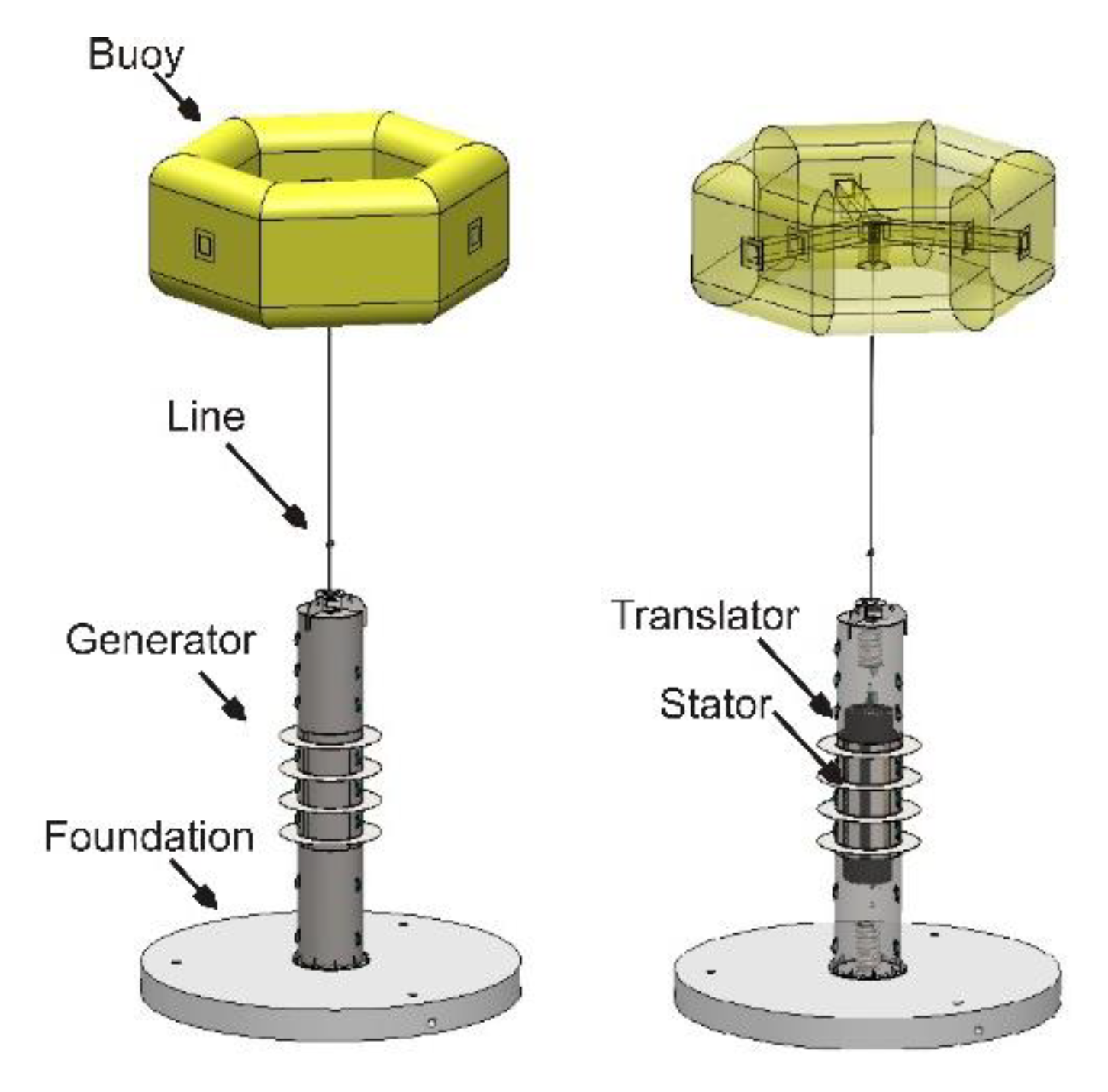
The ocean waves are an attractive renewable energy source as they offer high utilization, no fuel cost as well as a high power density, and a number of different research groups around the world are currently investigating the possibilities to convert this energy to electric energy [1,2,3,4,5]. The wave energy converter this paper focuses on, developed at Uppsala University, is a linear direct driven permanent magnet generator placed on the seabed connected by a line to a point absorbing buoy. The linear design is chosen to follow the motions of the waves, giving the system a simpler mechanical design and the choice of working with permanent magnets is to achieve a higher efficiency and reducing the maintenance. The moving part inside the generator is known as the translator whereas the conductor, the cable-winding, is inserted in the stationary part, known as the stator, illustrated in Figure 1. The magnetic circuit is designed with surface mounted Nd-Fe-B magnets, presented in Figure 2, and as the buoy moves with the waves a relative motion between the translator’s permanent magnets and the stator’s windings is achieved.
The specific generator this paper focuses on is presented in Table 1. Main dimensions are chosen based on wave climate at the specific area, insulation of the electric design, the electric system, manufacturability and overall cost. The generator’s magnetic and electromagnetic parameters have been developed in a finite element method simulation tool, further described in [6]. Based on these results, the generator is calculated to induce a line to line RMS voltage of 450 V at a translator speed of 0.7 m/s, connected to a nominal load of 12 ohm. For more information about the concept, see [7].
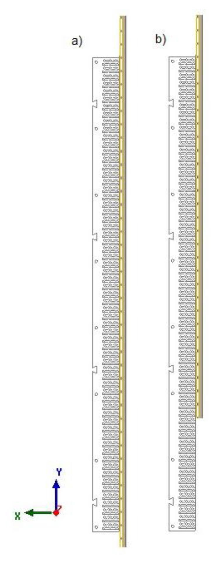
To achieve a higher active time, the generator is designed with a translator longer than the stator, presented in Figure 1 and Table 1. The generator’s operation state is therefore divided in to two intervals. During Interval I, presented in Figure 2a, as one magnet slips out another slips into the stator, and the stator remains 100% active. During Interval II, presented in Figure 2b, the active area decreases as the translator starts to slip out of the stator.
Studies of the longitudinal ends static impact with both linear [8] and non-linear [9] reluctance models have previously been presented in the literature. Reference [10] develops a dynamic model where the longitudinal ends effects are presented as a second magnetic wave within the air gap, whereas [11,12] includes the end effects by introducing an end effect correction factor during the dynamic calculations. Reference [12] further gives a review of the impact of the longitudinal end effects and presents results based on numerical calculations are presented for a linear induction motor. Reference [13] utilizes the space harmonic analysis to further study the secondary effects of the longitudinal ends and [14] presents an analytical model focusing on the detent force, caused by the longitudinal ends.
However, as the electrical frequency, saturation and geometric parameters strongly affects the consequences of the longitudinal ends, it is difficult to utilize the conclusions from the studies found in the literature and connect them to the linear generator here presented, as those parameters both differs from design to design and varies due to electrical loading and mechanical frequency. The possible drawbacks due to the longitudinal ends and its impact are therefore here, in this specific linear generator design, not known, leaving the designer with a gap of information. As the possibility of an increased losses and cogging force can affect both the mechanical design as the risk for fatigue increases, the machines efficiency and the energy absorption, is an investigation thereby of high interest. Therefore, the authors here present a unique study, based on numerical calculations, presenting the impact of the drawbacks of the longitudinal ends in the linear permanent magnetic generator.
2. Theory
2.1. The Magnetic Circuit in a Linear Permanent Magnet Machine
As stated above, the magnetic circuit of a linear and rotating machine differs in one fundamental property, the non-existing longitudinal ends in a rotating machine. In a rotating machine does the flux from one magnet follows the stator teeth and divides into two, more or less equal, flux path in the stator yoke. An evenly distribution of the flux in the stator and the rotor is achieved. However, the outermost magnet in a linear machine has only one return path through the stator, i.e., the two outermost magnets are pairwise coupled. As the translator moves and the outmost magnet slips in or out of the stator, the magnet changes their coupled partners. A change of the flux component in the translator, not existing in the rotor in a rotating machine, appears. The time-dependent flux component induces eddy currents in the non-laminated translator with the drawback of both decreasing efficiency and possibly causes thermal issues [10,11].
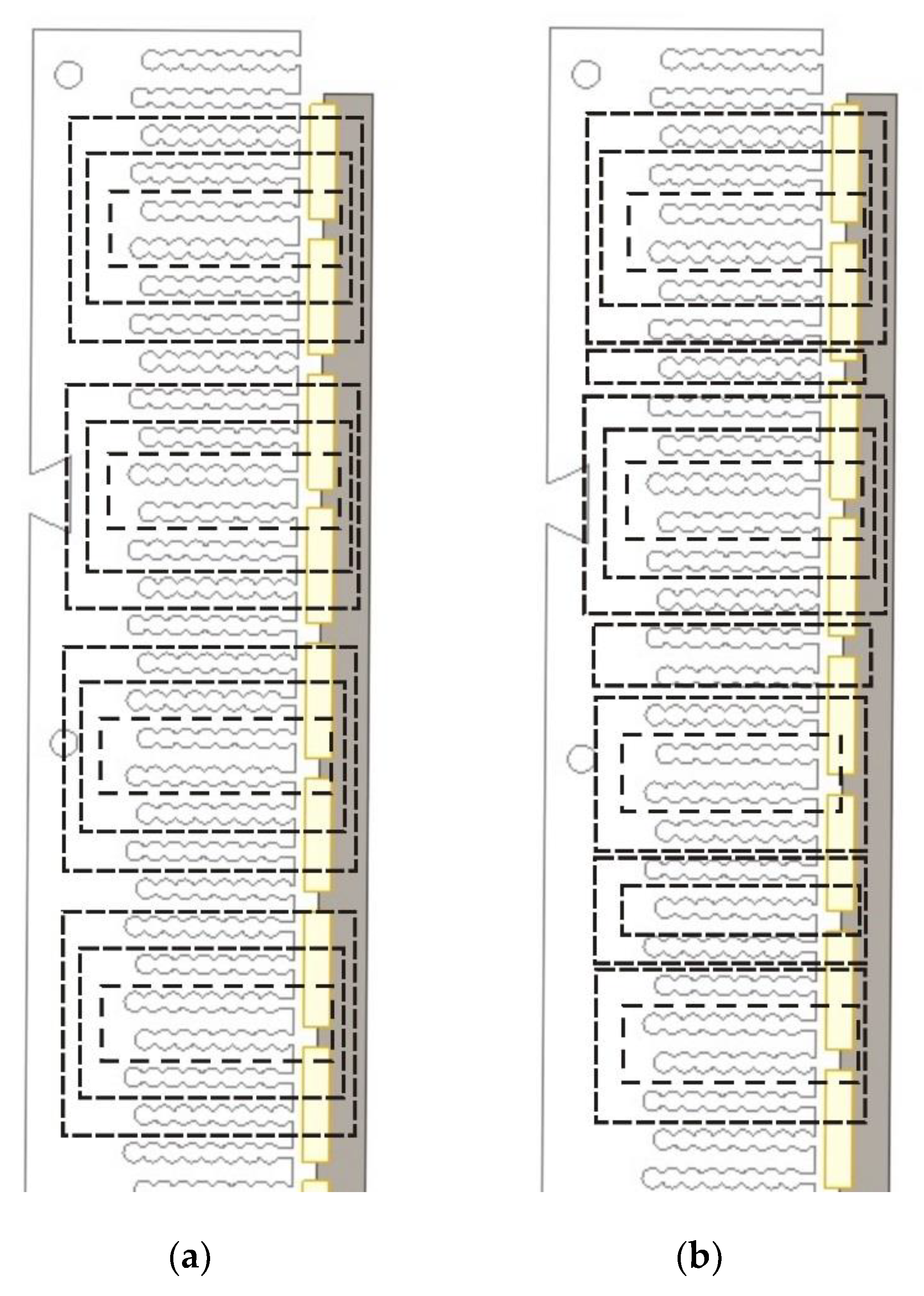
Further, the longitudinal ends are noticeable in other ways. As written above, the chosen dimensions of the translator and stator divide the operation state in two different intervals. During Interval II, the active area decreases as the translator slips out of the stator and the machine is constantly changing from being a generator with an even number of magnets to a generator with an odd number of magnets, and vice versa. When an even number of magnets are active, the magnetic flux is grouped pair wise throughout the machine, illustrated in Figure 3a, whereas for a circuit with an odd number of active magnets, the flux goes from a grouped pattern at the longitudinal ends to an evenly distributed pattern in the middle, presented in Figure 3b [10].
These two phenomena, giving rise to changes of the flux components in the translator, results in both eddy current losses, Peddy Equation (1), and hysteresis losses, Physteresis, Equation (2) [14].
keddy represents the eddy current loss coefficient, f the frequency of the changing magnetic field, Bx, the amplitude of the changing magnetic field density in x-direction, kf is the stacking factor, and is a material coefficient. Table 2 presents the value of the different coefficients.
The iron losses are in the chosen simulation tool based on parameters from the Epstein Square loss data test. The iron losses estimations, obtained by Equation (1), include therefore only the iron losses from the flux change in the x-direction [10]. To include the core losses due to flux changes in the y-direction, i.e., the rotating field, a correction term has been included in the calculations, see Equation (3) [15].
Γ represents the degree of rotation, and is defined as the fundamental axis ratio of the flux density, Equation (4).
The term, is a weight factor determining the additional loss due to the rotating flux. According to [15], can the term be approximated to a constant value of 0.6 when the flux density is high. The authors have chosen to work with this constant value, partly because data for rotational loss in the translator material were not available and due to the high flux density in the translator.
2.2. Cogging Force
As the stator is constructed of laminated electro-sheets, the stator teeth become magnetised. An attractive force between the stator and the translator appears. As the translator moves, a horizontal and a vertical component of the force arise. The magnetic force acting in the same direction as the translator’s motion at no load is known as the cogging force. Several methods, for example Maxwell’s stress tensor, MST, and Coulomb’s virtual work, CVW, Equation (5) can be utilized to calculate this cogging force. [16] They give theoretically the same results and are based on solutions of the magnetic field quantities.
Wmagnetic represents the magnetic energy in the air gap. As the energy is derived from the absolute-value of the fields, not the direction of each term, assumptions that the field-density in the air-gap is constant has been done, and the total amount of energy in the airgap can be calculated from a fix mesh-line. The authors have therefore chosen to work with Coulomb’s virtual work to identify the cogging force at no load. For further reading about Coulomb’s virtual work, see [17,18].
3. Simulation Setup
In order to simulate the electric machine’s behaviour at different conditions, electromagnetic simulations utilizing FEM are performed. The electric and magnetic field within the electric machine is assumed to be axi-symmetrical and is therefore modelled as a two dimensional object. The machine parts are assigned different material properties such as conductivity, permeability, density, sheet thickness etc. The mesh is finer close to more interesting parts like the air gap and coarser in areas such as the back iron of the stator. The electromagnetic model is solved in the finite element environment Maxwell Ansys. Simulations can be performed either in a stationary mode where the results are given for a fixed translator position or in a dynamic mode including the time-dependence. The numerical calculations have been verified with experimental results for different generators [19,20,21,22].
3.1. Core Losses in the Translator
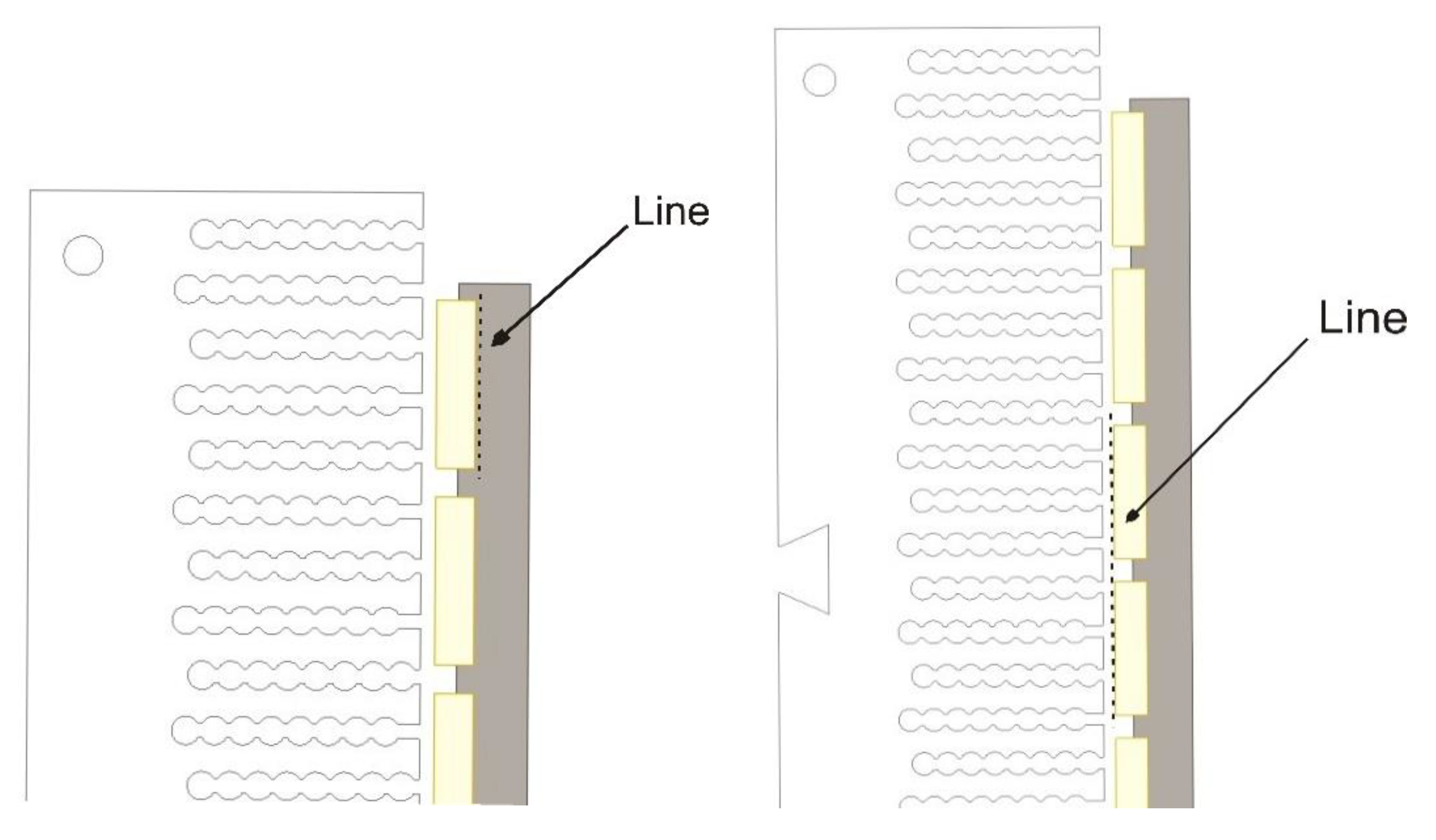
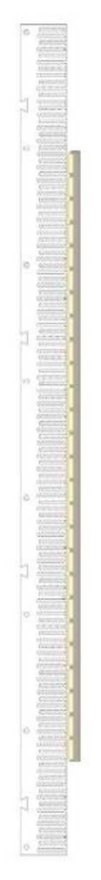
As written above, a consequence of the longitudinal ends, a change of the flux component appears in the translator as the outmost magnet slips out of the stator, resulting in both eddy currents and hysteresis losses. To be able to calculate the size of these losses, the change of the Bx-component has to be known during a dynamic simulation where two magnets are slipping out of the stator. The authors have chosen to, with help of a finite element tool, calculate the requested Bx-component at each mesh-nod in a line, placed directly behind a magnet, illustrated in Figure 4. With information how the Bx-component changes at each mesh-nod during one complete dynamic cycle, the iron losses can be calculated.
3.2. Cogging Force
As the authors have chosen to work with Coulomb’s virtual work to identify the cogging force the magnetic energy in the air-gap has to be found. A similar technique, described above, was utilized to calculate the requested parameters, required to calculate the cogging force. At a line, placed directly before two magnets, illustrated in Figure 4, the energy-term at each mesh-node, was found. As the energy is derived from the absolute-value of the fields, not the direction of each term, assumptions that the field-density in the air-gap is constant has been done, and the total amount of energy in the airgap can be calculated from the line.
To create a better picture of the longitudinal ends impact on the cogging force, simulations where the stator’s longitudinal ends are neglected were performed. During these simulations, the model in Figure 5 was utilized.
4. Results
The following results from the finite element method simulation tool are performed with the generator operating at no load. For defined directions, see the coordinate system in Figure 2.
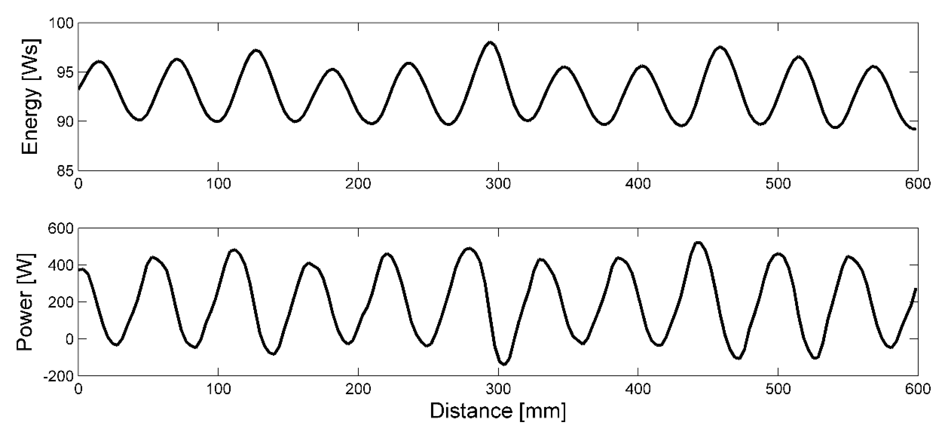
As stated above, the change of the magnetic flux component give rise to core losses in the translator. The authors have chosen to perform a simulation with a constant velocity, v = 0.7 m/s. The energy and losses in the translator during Interval I are presented in Figure 6.
The results present a periodically varying value of the magnetic energy and the power loss, where the peaks appear with the same distance as the pole width. As the power loss reaches up to 0.5 kW, the losses in the translator reaches up to 2% of the absorbed power, for a rated generator-power of 25 kW.
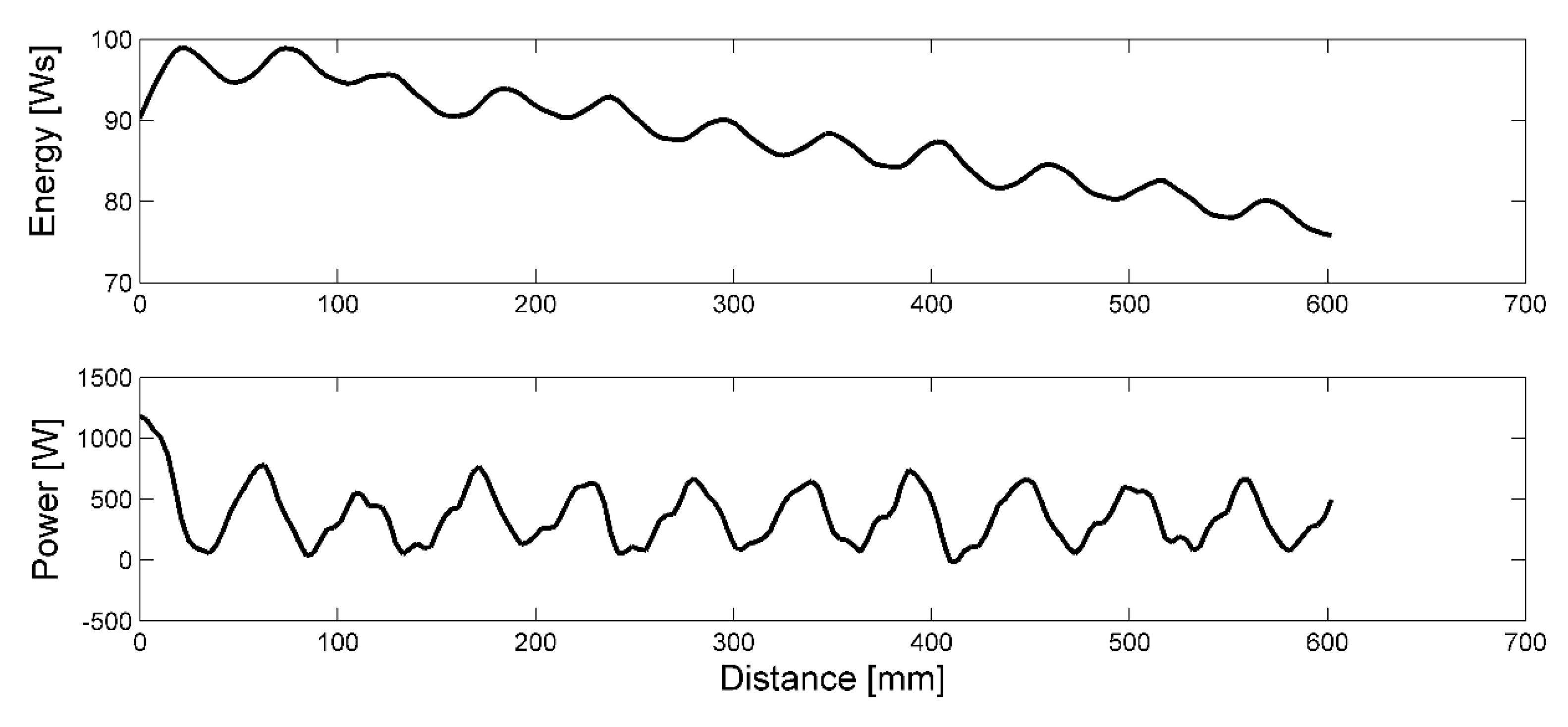
The energy and losses in the translator during Interval II are presented in Figure 7.
As expected, the total energy in the translator decreases during Interval II as the number of poles facing the stator decreases, i.e., the reluctance in the magnetic circuit increases with the result of a decreasing energy density in the translator. The maximum value of the power loss is, however, constant. Again, the periodically pattern appears at each pole width.
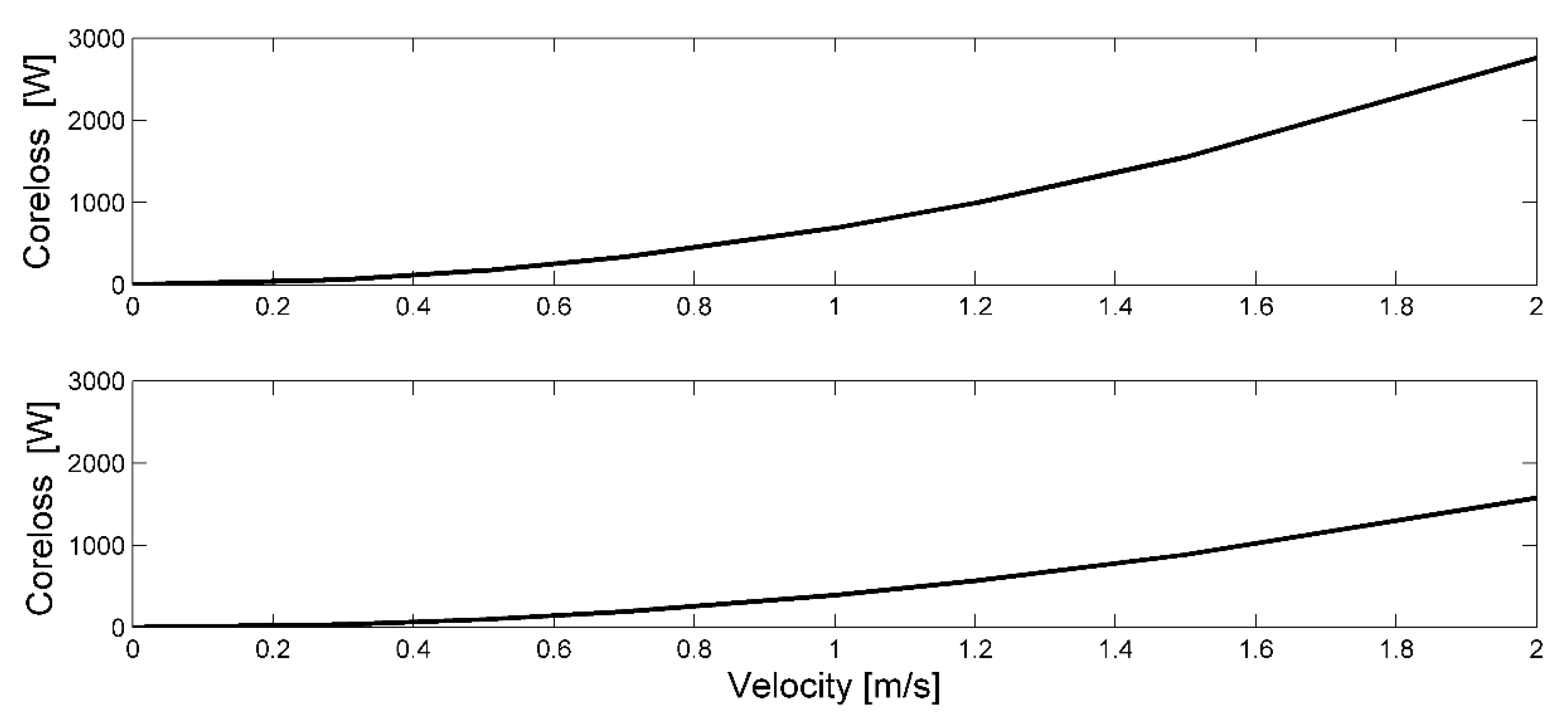
Both eddy current and hysteresis losses increase with the frequency, therefore, to achieve a proper investigation of the losses, the authors have chosen to perform simulations with different velocities. Figure 8, upper graph, presents the core losses in the translator during Interval I whereas Figure 8, lower graph, presents the core losses in the translator during Interval II at different velocities.
As Figure 8 presents, the losses increase with the frequency.
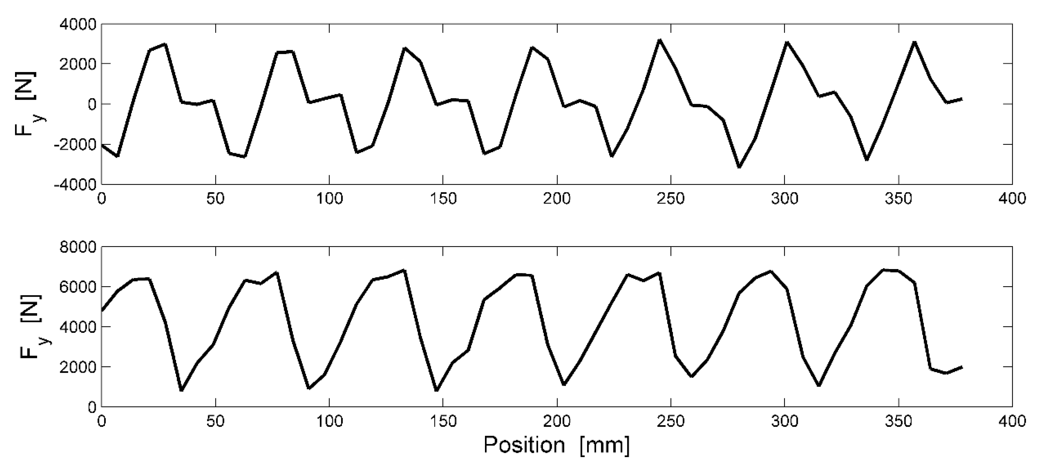
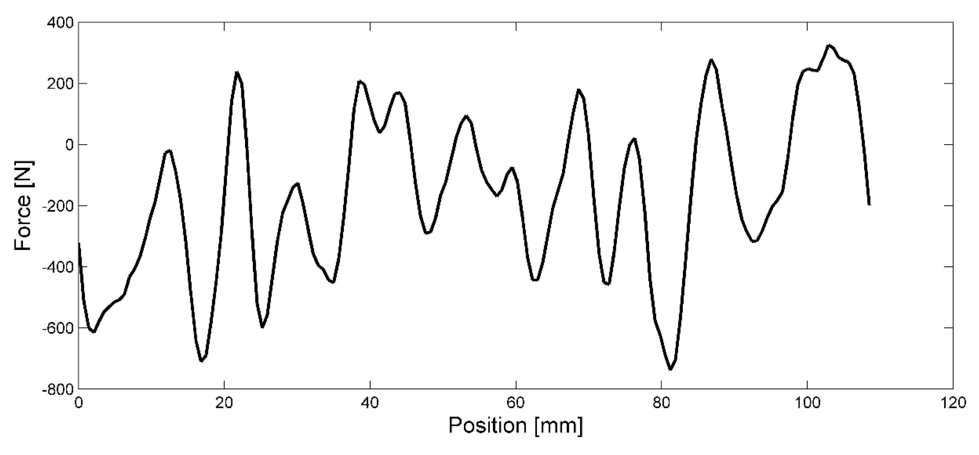
Since the cogging force is independent of the translator’s velocity, the authors have chosen to only perform a simulation with a translator velocity v = 0.7 m/s in the positive direction, see the coordinate system in Figure 2. The direction of the parameters, presented in the graphs below, refers to the same coordinate system. Figure 9, upper graph presents the total cogging force during Interval I, Figure 9, lower graph, represents Interval II, whereas Figure 10 presents the cogging force when the longitudinal end effects are neglected.
The amplitude of the cogging force changes drastically when the generator’s operation point changes from Interval I to Interval II, even though the peak to peak value stays constant. The two outmost magnets during Interval I seem to smooth out each other, which results in a smaller value on the amplitude of the total cogging force.
As Figure 10 presents, when the longitudinal end effect is neglected, the amplitude reduces drastically.
5. Discussion
The results present a periodically varying value of the magnetic energy and the cogging force, where the peaks appear with the same distance as the pole width. As expected, the total energy in the translator decreases during Interval II as the number of poles facing the stator decreases, i.e., the reluctance in the magnetic circuit increases with the result of a decreasing energy density in the translator. The amplitude of the core loss is on the other hand independent of the total amount of energy, i.e., the number of active magnets, presented in Figure 7.
The amplitude of the cogging force changes drastically when the generator’s operation point changes from Interval I to Interval II. The two outmost magnets during Interval I seem to smooth out each other, which results in a smaller value on the amplitude of the total cogging force.
Secondary effects of the increases cogging force could impact the buoy’s capability to absorb energy from the ocean waves and it may impact the survivability of the mechanical structure. The frequency of the cogging force is of the same magnitude as the electrical frequency, the authors thereby believe that the buoy perceives the cogging force as the electrical damping force, i.e., as an additional damping every time the force is directed in the opposite direction of the translator’s velocity. The additional force decreases the translator’s capability to accelerate and achieve a high speed in the positive direction, and a secondary effect of the cogging can thereby be a decreasing power output. The opposite happens when the cogging force is directed in the direction of the translator’s velocity. The magnetic force increases the accelerating force, and increases the translator’s capability to achieve a higher velocity.
6. Conclusions
The longitudinal end effects of a linear permanent magnet synchronous generator, suggested for a wave power plant, have been studied. Parts of the results have been compared with simulations where the longitudinal ends are neglected.
The longitudinal end effects were identified to have an important impact on the generator’s magnetic circuit, such as significant contribution to the cogging force and core losses in the translator.
The results present a periodically varying value of the magnetic energy in the translator, where the peaks appear at the same distance as the pole width. The amplitude of the core loss is on the other hand independent of the total amount of energy, i.e., the number of active magnets, illustrated in Figure 8. The authors therefore state the following: the core losses in the translator are mainly raised by the shift of coupled magnets when the outermost magnet slips in to and out of the stator. In a rotating generator, where the longitudinal ends do not exist, these core losses are very likely significantly lower.
The cogging force has the same periodical shape as the total energy in the translator with peaks every 55 mm. If the cogging force was mainly raised by the stator teeth, the force would have had a much higher frequency, i.e., the peaks would be located with the same distance as the teeth. For this reason, the following statement has been made: the cogging force is mainly produced by the longitudinal ends, i.e., the main contribution to the total value of the force is when a magnet slips in or out of the stator. The results from the simulation where the longitudinal ends effects are neglected, see Figure 10, strengthen this conclusion. In the presented result in Figure 10, the amplitude of the force is significantly lower with a higher frequency.
However, the authors conclude that the cogging force neither increases nor decreases the wave power plant’s capability to absorb energy at rated speed and power output. The cogging force is synchronous with the electromagnetic damping force but significant smaller. At the relatively low speed that the generator is rated for, 0.7 m/s, the electromagnetic damping force is many times greater the cogging force when the output power reaches 25 kW.
The additional core losses in the translator, caused by the longitudinal ends are relatively large. The authors do however not believe that the losses can cause thermal problems for the surface mounted permanent magnets, and is thereby not affecting the wave power plant system negative. The losses are also not large enough to motivate the use of a bigger buoy for wave energy absorption and do not cause any extra strain on the mechanical design.
However, the results call for additional investigations and comparisons with similar investigations on rotating generators, in order to fully identify the secondary effects of the longitudinal ends in a linear machine. Identification of these effects is necessary in order to determine which different design criteria should be applied by engineers depending on if they are constructing a linear or rotating machine.
Author Contributions
B.E. built the model, performed the simulations and calculations and wrote the paper. M.L. contributed with discussions, ideas and valuable insights. All authors have read and agreed to the published version of the manuscript.
Funding
This research was carried out as part of the Statkraft Ocean Energy Research Program, sponsored by Statkraft. (www.statkraft.no) The support is gratefully acknowledged. The authors would also like to thank The Swedish Research Council, Grant No 2009-3417, for their financial support.
Conflicts of Interest
The authors declare no conflicts of interest.
References
- Falcão, A. Wave energy utilization: A review of the technologies. Renew. Sustain. Energy Rev. 2010, 14, 899–918. [Google Scholar] [CrossRef]
- Previsic, M. Wave power technologies. In Proceedings of the 2005 IEEE Power Engineering Society General Meeting, San Francisco, CA, USA, 12–16 June 2005; Volume 2, pp. 2011–2016. [Google Scholar]
- Polinder, H.; Scuotto, M. Wave energy converters and their impact on power systems. In Proceedings of the 2005 Institute of Electrical and Electronics Engineers (IEEE) International Conference on Future Power Systems, Amsterdam, The Netherlands, 18 November 2005; p. 9. [Google Scholar]
- Shibaike, A.; Sanada, M.; Morimoto, S. Suitable configuration of permanent magnet linear synchronous generator for wave power generation. In Proceedings of the 2007 Institute of Electrical and Electronics Engineers (IEEE) Power Conversion Conference, Nagoya, Japan, 2–5 April 2007; pp. 210–215. [Google Scholar]
- Azza, A.; Faiad, I.A. Gowaid linear generator technologies for wave energy conversion applications: A review. In Proceedings of the 2018 53rd International Universities Power Engineering Conference (UPEC), Glasgow, UK, 4–7 September 2018. [Google Scholar]
- Ekergard, B. Full Scale Applications of Permanent Magnet Electromagnetic Energy Converters—From Nd2Fe14B to Ferrite. Ph.D. Thesis, Uppsala University, Uppsala, Sweden, October 2013. [Google Scholar]
- Leijon, M.; Danielsson, O.; Eriksson, M.; Thorburn, K.; Bernhoff, H.; Isberg, J.; Sundberg, J.; Ivanova, I.; Sjöstedt, E.; Ågren, O.; et al. An electrical approach to wave energy conversion. Renew. Energy 2006, 31, 1309–1319. [Google Scholar] [CrossRef]
- Danielsson, O.; Leijon, M. Flux distribution in linear permanent-magnet synchronous machines including longitudinal end effects. IEEE Trans. Magn. 2007, 43, 3197–3201. [Google Scholar] [CrossRef]
- Polinder, H.; Slootweg, J.G.; Hoeijmakers, M.J.; Compter, J.C. Modeling of a linear pm machine including magnetic saturation and end effects: Maximum force-to-current ratio. IEEE Trans. Ind. Appl. 2003, 39, 1681–1688. [Google Scholar] [CrossRef]
- Faiz, J.; Jagari, H. Accurate modeling of single-sided linear induction motor considers end effect and equivalent thickness. IEEE Trans. Magn. 2000, 36, 3785–3790. [Google Scholar] [CrossRef]
- Adamiak, K.; Ananthasivam, K.; Dawson, G.; Eastham, A.; Gieras, J. The causes and consequences of phase unbalance in single-sided linear induction motors. IEEE Trans. Magn. 1988, 24, 3223–3233. [Google Scholar] [CrossRef]
- Pai, R.M. Polyphase linear induction motors with non-magnetic secondaries: A review on longitudinal-end and transverse-edge effects. Electr. Mach. Power Syst. 1988, 15, 73–80. [Google Scholar] [CrossRef]
- Sang-Yong, J.; Hyun-Kyo, J.; Jang-Sung, C.; Do-Hyun, K.; Ji-Hyun, H. Dynamic characteristics of partially excited permanent magnet linear synchronous motor considering end-effect. In Proceedings of the IEEE International Electric Machines and Drives Conference, Cambridge, MA, USA, 17–20 June 2001. [Google Scholar]
- Ma, M. Analytical methods for minimizing detent force in long-stator PM linear motor including longitudinal end effects. In Proceedings of the 2015 Institute of Electrical and Electronics Engineers (IEEE) Magnetics Conference (INTERMAG), Beijing, China, 11–15 May 2015; p. 1. [Google Scholar]
- Ranlof, M.; Wolfbrandt, A.; Lidenholm, J.; Lundin, U. Core loss prediction in large hydropower generators: Influence of rotational fields. IEEE Trans. Magn. 2009, 45, 3200–3206. [Google Scholar] [CrossRef]
- Stranges, N.; Findlay, R.D. Methods for predicting rotational iron loss in three phase induction motor stators. IEEE Trans. Magn. 2000, 36, 3112–3114. [Google Scholar] [CrossRef]
- Fano, R.M.; Chu, L.J.; Adler, R.B. Electromagnetic Fields, Energy and Force; John Wiley & Sons, Inc.: Hoboken, NJ, USA, 1960. [Google Scholar]
- Coulomb, J.L. A Methodology for the determination of global electromechanical quantities from a finite analysis and its application to the evaluation of magnet forces, torques and stiffness. IEEE Trans. Magn. 1983, 19, 2514–2519. [Google Scholar] [CrossRef]
- Eriksson, S.; Solum, S.; Bernhoff, H.; Leijon, M. Simulations and experiments on a 12 kW direct driven PM synchronous generator for wind power. Renew. Energy 2008, 33, 674–681. [Google Scholar] [CrossRef]
- Eriksson, S.; Bernhoff, H.; Leijon, M. FEM simulations and experiments of different loading conditions for a 12 kW direct driven PM synchronous generator for wind power. Int. J. Emerg. Electr. Power Syst. 2010, 10, 3. [Google Scholar] [CrossRef]
- Eriksson, S.; Bernhoff, H.; Leijon, M. A 225 kW direct driven PM generator adapted to a vertical axis wind turbine. Adv. Power Electron. 2011, 2011, 239061. [Google Scholar] [CrossRef] [Green Version]
- Leijon, M.; Bernhoff, H.; Ågren, O.; Isberg, J.; Sundberg, J.; Berg, M.; Karlsson, K.E.; Wolfbrandt, A. Multiphysics simulation of wave energy to electric energy conversion by permanent magnet linear generator. IEEE Trans. Energy Convers. 2005, 20, 219–224. [Google Scholar] [CrossRef]
- Danielsson, O.; Eriksson, M.; Leijon, M. Study of a longitudinal flux permanent magnet linear generator for wave energy converters. Int. J. Energy Res. 2006, 30, 1130–1145. [Google Scholar] [CrossRef]
Figure 1.
Overall illustration of the linear generator the paper focus on.

Figure 2.
Illustration of the two different intervals the generator is operating in; (a) Interval I, (b) Interval II.
Figure 2.
Illustration of the two different intervals the generator is operating in; (a) Interval I, (b) Interval II.

Figure 3.
(a) The pair wise grouped flux with an even number of active magnets contra (b) the flux distribution with an odd number of active magnets.
Figure 3.
(a) The pair wise grouped flux with an even number of active magnets contra (b) the flux distribution with an odd number of active magnets.

Figure 4.
To find the requested values at each time-step, an additional mesh-line has been included in the simulation, illustrated above.
Figure 4.
To find the requested values at each time-step, an additional mesh-line has been included in the simulation, illustrated above.

Figure 5.
The model presents a translator shorter than the stator, i.e., the longitudinal ends is neglected.
Figure 5.
The model presents a translator shorter than the stator, i.e., the longitudinal ends is neglected.

Figure 6.
The upper graph presents the total energy whereas the lower graph presents the power loss in the translator during Interval I.
Figure 6.
The upper graph presents the total energy whereas the lower graph presents the power loss in the translator during Interval I.

Figure 7.
The upper graph presents the total energy whereas the lower graph presents the power loss in the translator during Interval II.
Figure 7.
The upper graph presents the total energy whereas the lower graph presents the power loss in the translator during Interval II.

Figure 8.
The core loss in the translator at different velocities’ during upper graph) Interval I and lower graph) Interval II.
Figure 8.
The core loss in the translator at different velocities’ during upper graph) Interval I and lower graph) Interval II.

Figure 9.
The cogging force changes drastically when the generator’s operation point changes from Interval I to Interval II. The lower graph presents the cogging force both when the translator enters and leaves the stator.
Figure 9.
The cogging force changes drastically when the generator’s operation point changes from Interval I to Interval II. The lower graph presents the cogging force both when the translator enters and leaves the stator.

Figure 10.
The graph presents the cogging force result when the longitudinal end effects are neglected during one electric period.
Figure 10.
The graph presents the cogging force result when the longitudinal end effects are neglected during one electric period.


Table 1.
The main dimensions of the generator.
| Power | 25 kW |
| CorelossStator | 2 kW |
| Stator length | 2000 mm |
| Translator length | 3000 mm |
| Stroke length | 2000 mm |
| Airgap | 3 mm |
| Pole width | 55 mm |
Table 2.
The value of the coefficients.
| Parameter | Value |
|---|---|
| keddy | 2 × 10⁻³ |
| kf | 0.97 |
| kh | 0.05 |
© 2020 by the authors. Licensee MDPI, Basel, Switzerland. This article is an open access article distributed under the terms and conditions of the Creative Commons Attribution (CC BY) license (http://creativecommons.org/licenses/by/4.0/).
Share and Cite
MDPI and ACS Style
Ekergård, B.; Leijon, M. Longitudinal End Effects in a Linear Wave Power Generator. Energies 2020, 13, 327. https://0-doi-org.brum.beds.ac.uk/10.3390/en13020327
AMA Style
Ekergård B, Leijon M. Longitudinal End Effects in a Linear Wave Power Generator. Energies. 2020; 13(2):327. https://0-doi-org.brum.beds.ac.uk/10.3390/en13020327
Chicago/Turabian StyleEkergård, Boel, and Mats Leijon. 2020. "Longitudinal End Effects in a Linear Wave Power Generator" Energies 13, no. 2: 327. https://0-doi-org.brum.beds.ac.uk/10.3390/en13020327
Note that from the first issue of 2016, this journal uses article numbers instead of page numbers. See further details here.