High Performance Single-Phase Single-Stage Grid-Tied PV Current Source Inverter Using Cascaded Harmonic Compensators


Abstract
:1. Introduction
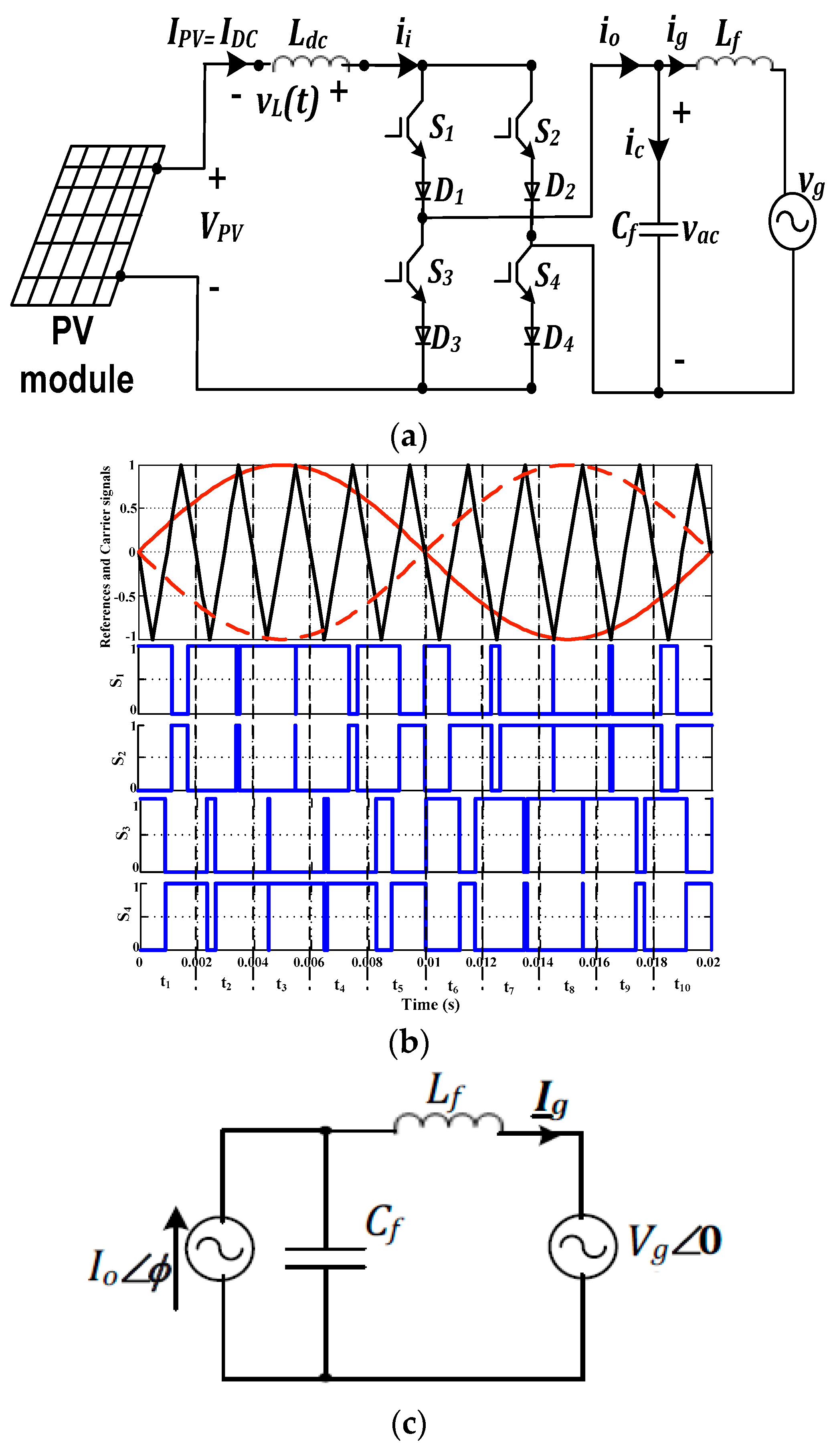
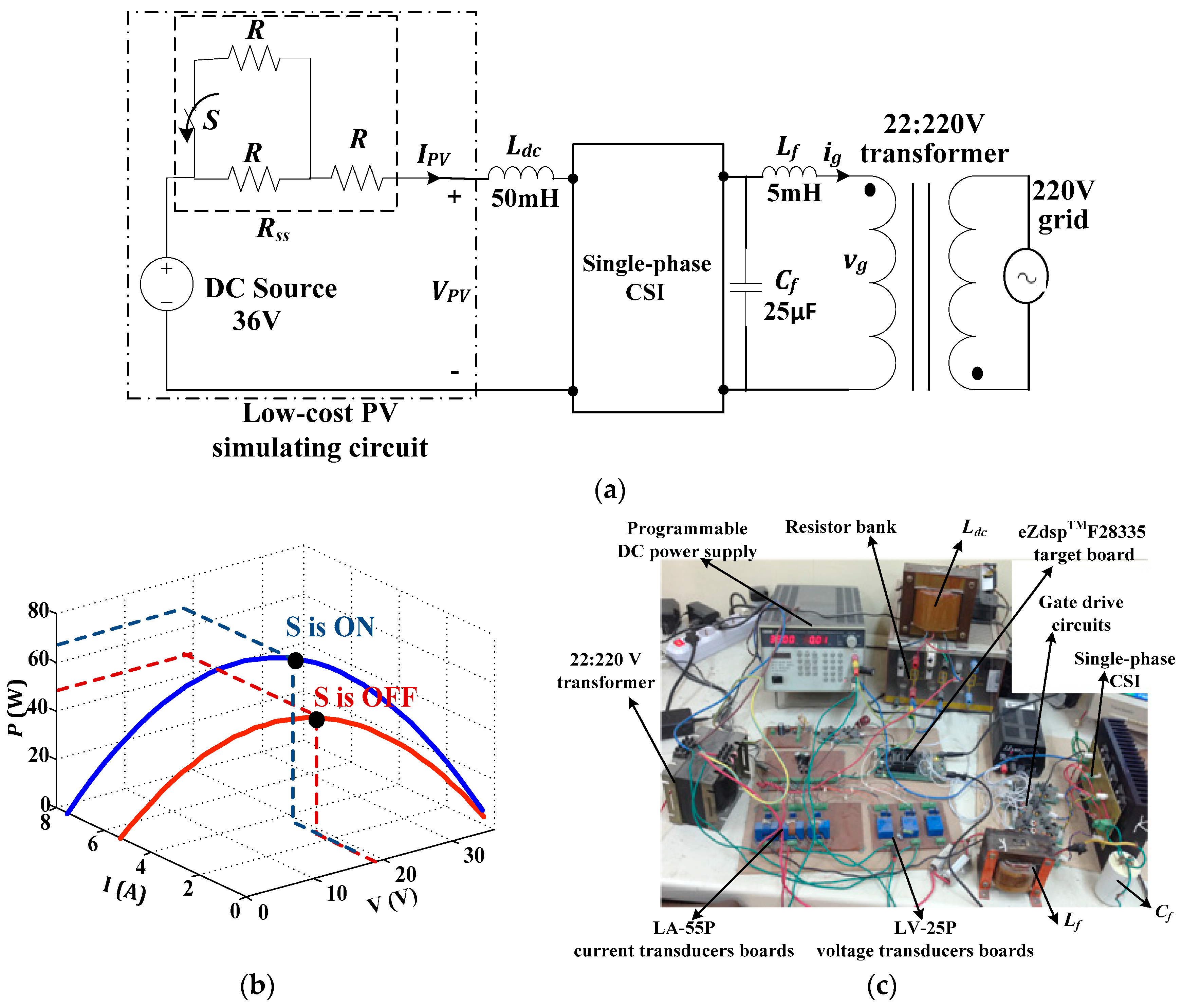
2. System under Investigation
2.1. Applied Pulse Width Modulation Scheme
2.2. System Modelling
2.3. Parameters’ Design
2.3.1. AC Output Filter
2.3.2. DC-Link Inductor
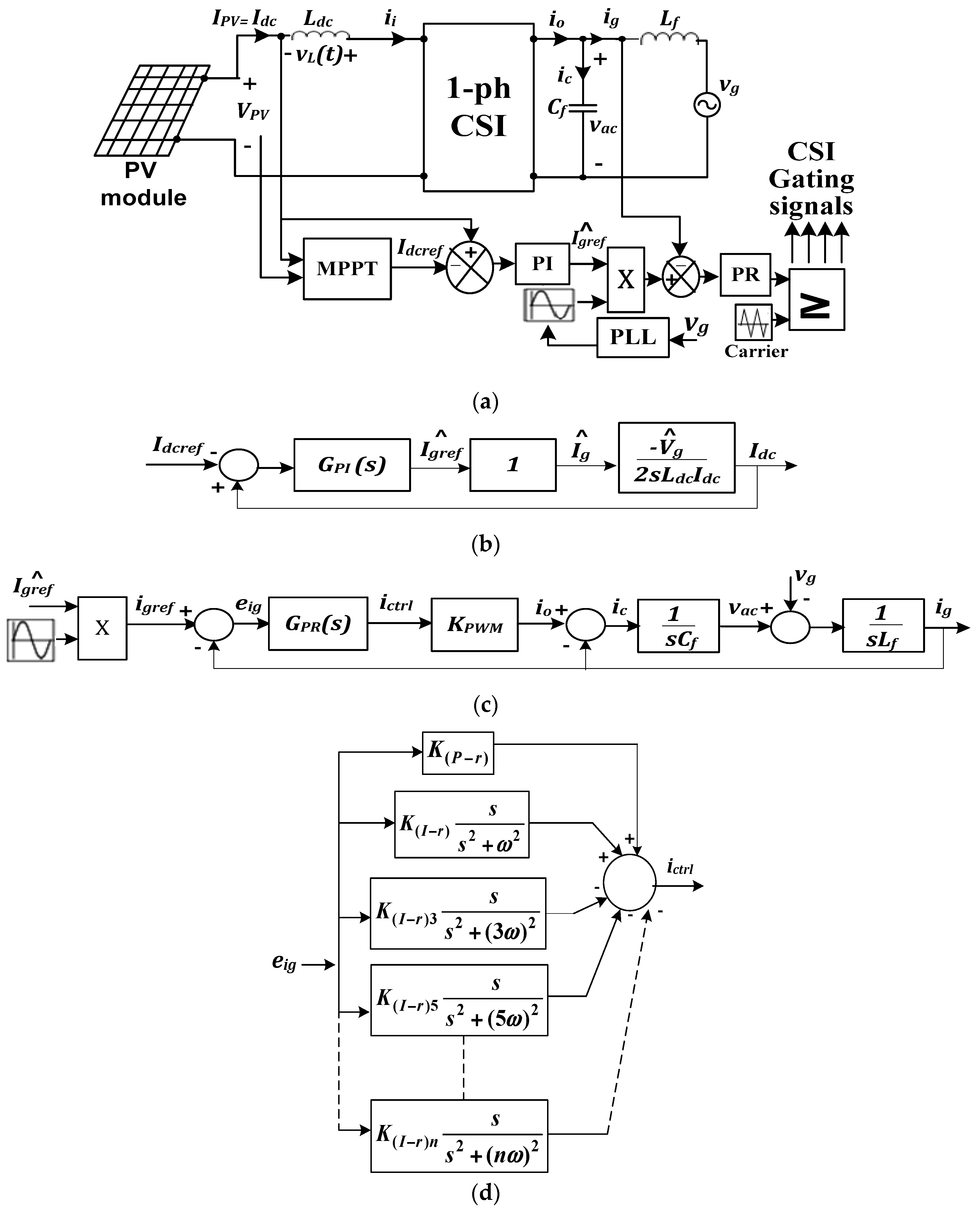
3. Proposed Control Scheme
3.1. CSI Control Loops
3.2. Outer DC-Link Current Control Loop
3.3. Inner Grid Current Control Loop
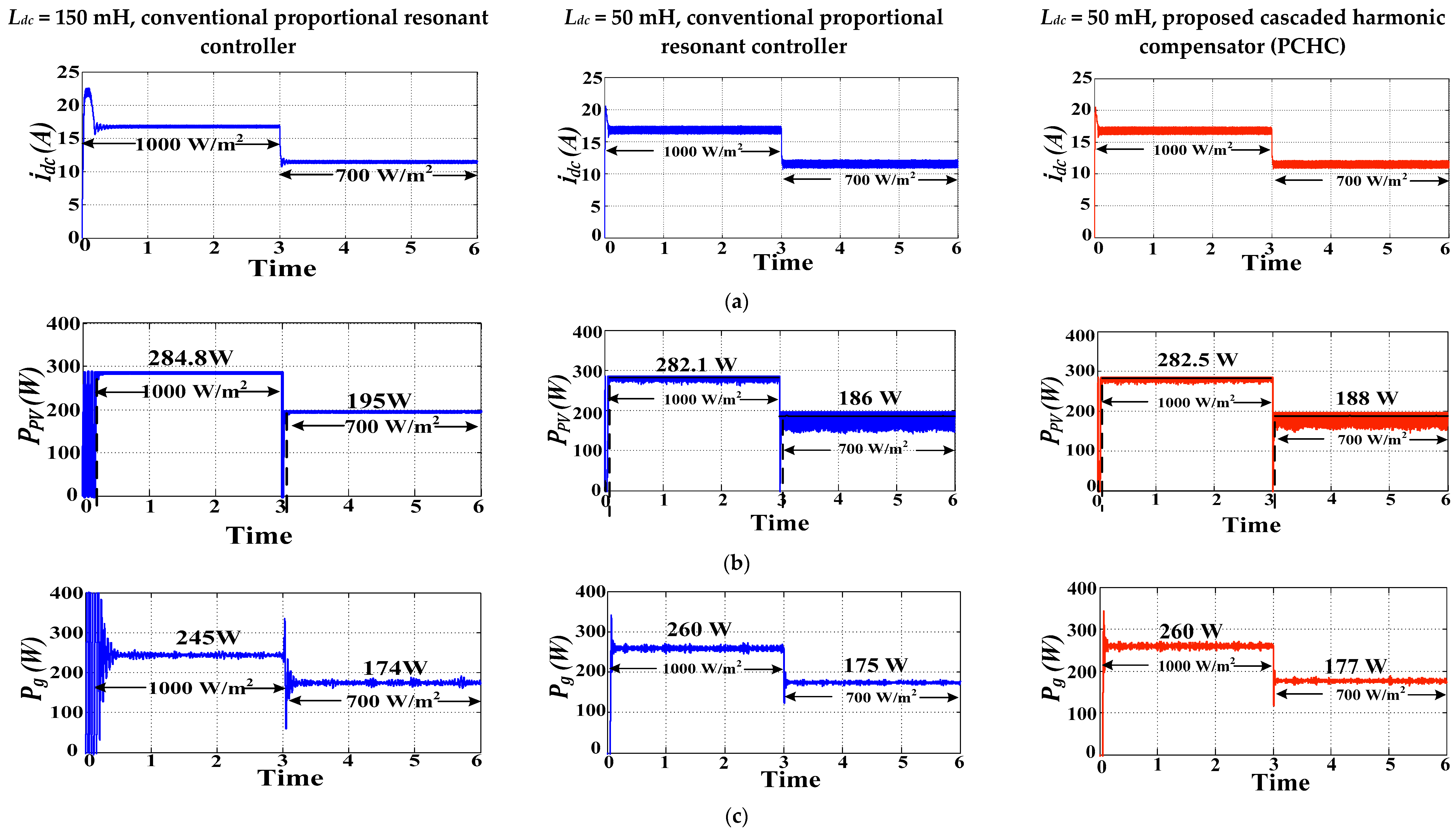
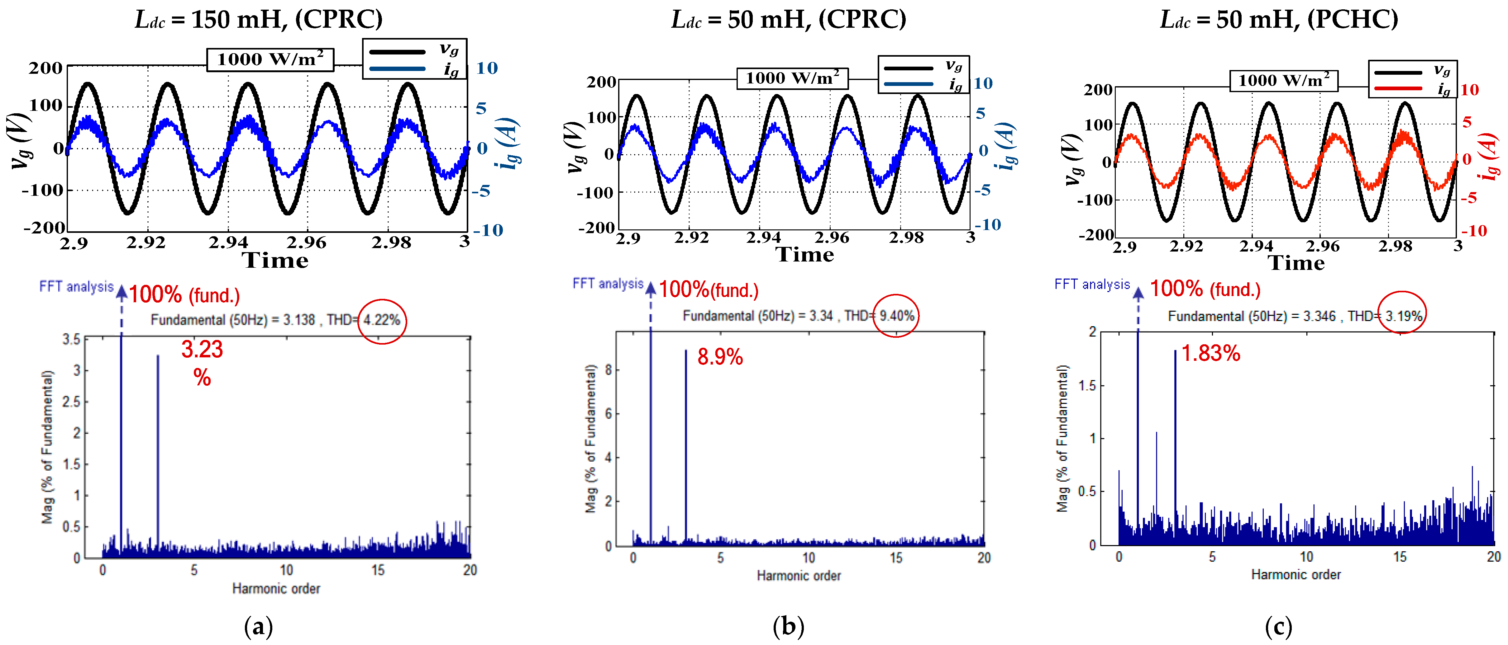
4. Simulation Results
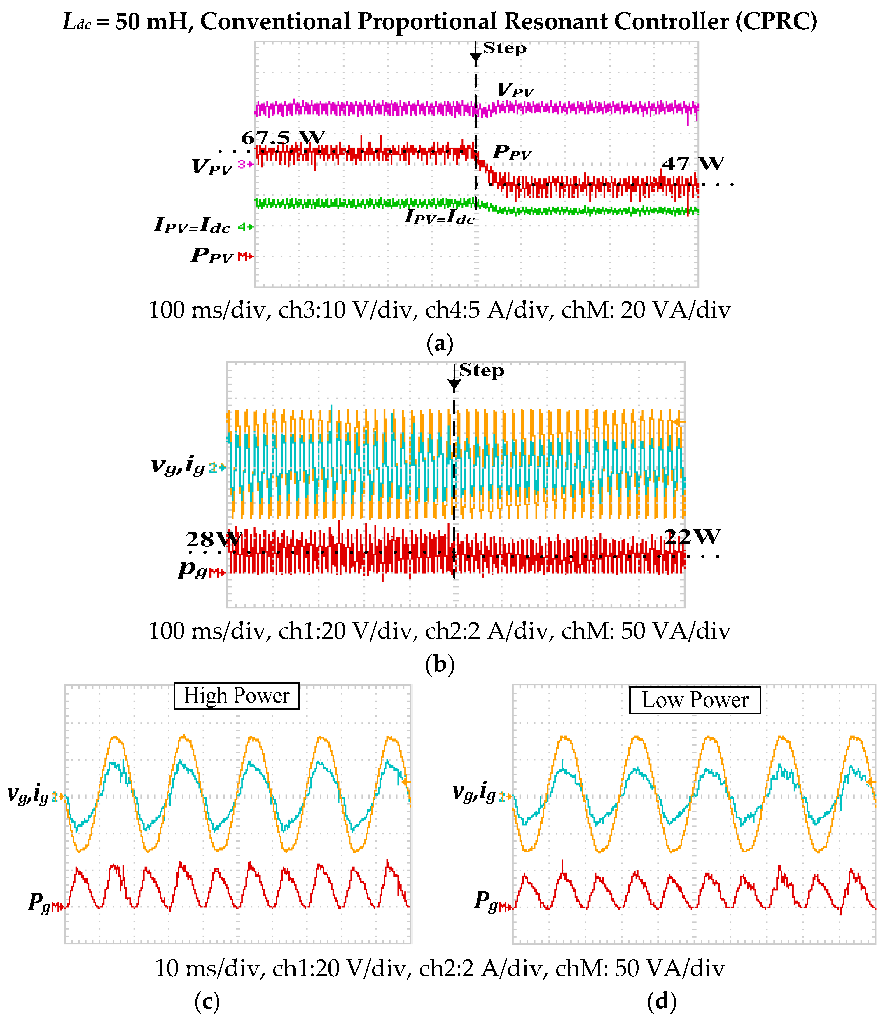
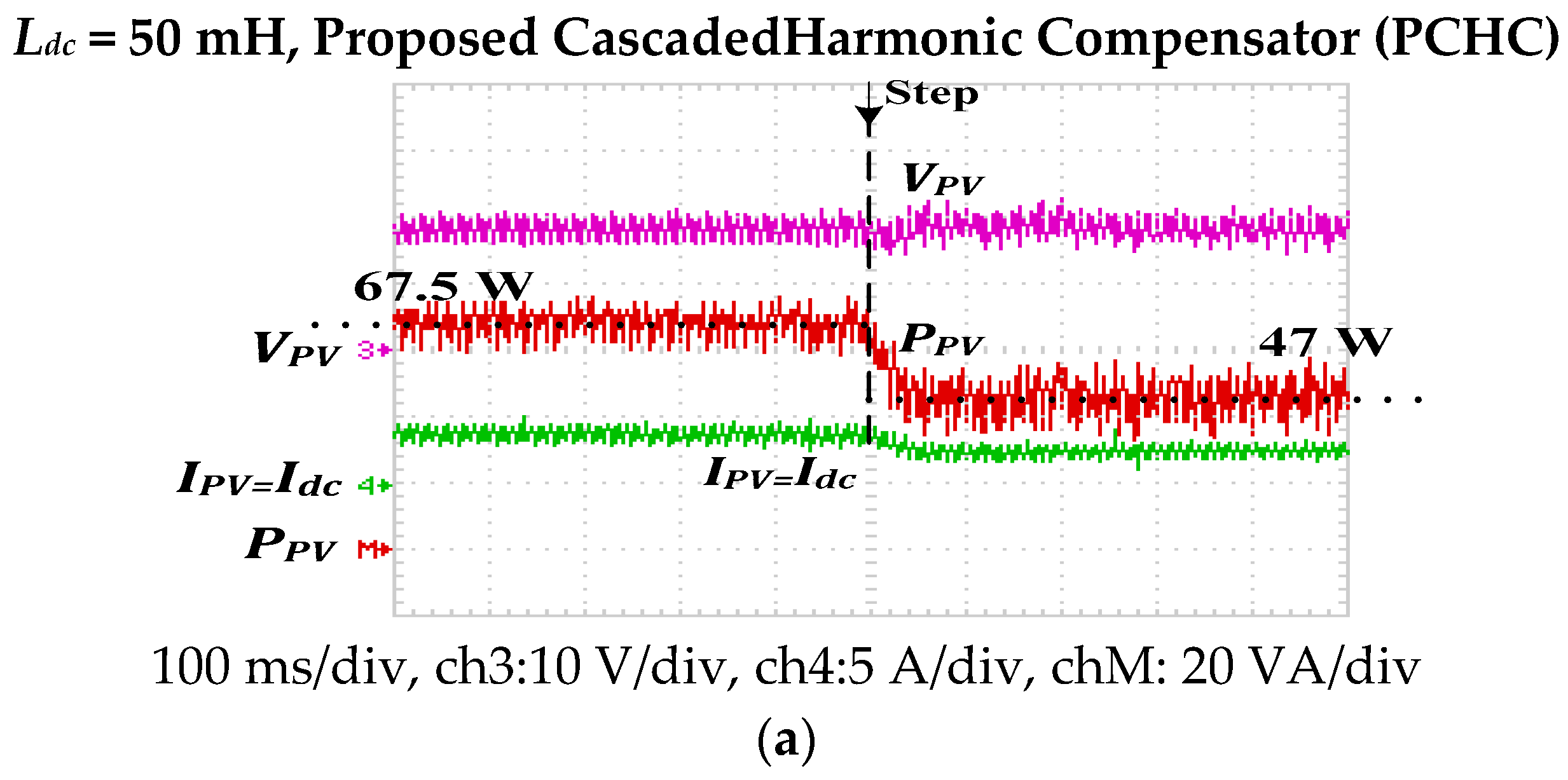
5. Experimental Results
6. Conclusions
7. Discussion
Author Contributions
Funding
Conflicts of Interest
Appendix A

Appendix B

| Reference | Hardware | PWM Technique | Harmonic Mitigation Method | Experimental THD | Advantages | Disadvantages |
|---|---|---|---|---|---|---|
| [20] | Single phase | PAM | Using PWM only | No experimental results (4.8% in simulation) | 1. Simplified PWM 2. No extra hardware | 1. Limited performance at low modulation indices 2. Not harmonic specific cancellation |
| [21] | Single phase | NPWM | Using PWM only | 4.42% | 1. Analogue based 2. Deteriorated THD at low power operation | |
| [25] | Single phase | SPWM | Using PWM only via 3rd harmonic cancellation | No experimental THD calculation (3.42% in simulation) | 1. Only mitigates 3rd harmonic grid current. | |
| [26] | Single phase | Modified carrier based | double-tuned parallel resonant circuit to attenuate the 2nd and 4th order harmonics at the inverter dc side | 2.3% | 1. Double action mitigation both hardware and software 2. High performance | 1. High cost and size 2. Bulky 3. Difficult to tune the double parallel filter |
| [27] | Single phase | Pulse transform witching table | Active buffer power decoupling circuit | 4.24% | 1. High performance 2. High power density | 1. More active semiconductors 2. High cost and size 3. bulky 4. Extra voltage sensor is needed |
| Proposed controller | Single phase | Modified sinusoidal | Software based Cascaded harmonic compensators for the grid current control | 3.19% | 1. High performance 2. Low cost and size 3. Less bulky 4. Easily tuned compensators | 1. Care must be taken at various DC-link inductor values specially at very low modulation indices |
Appendix C
| Simulation Analysis Parameters | Experimental Validation Parameters | |
|---|---|---|
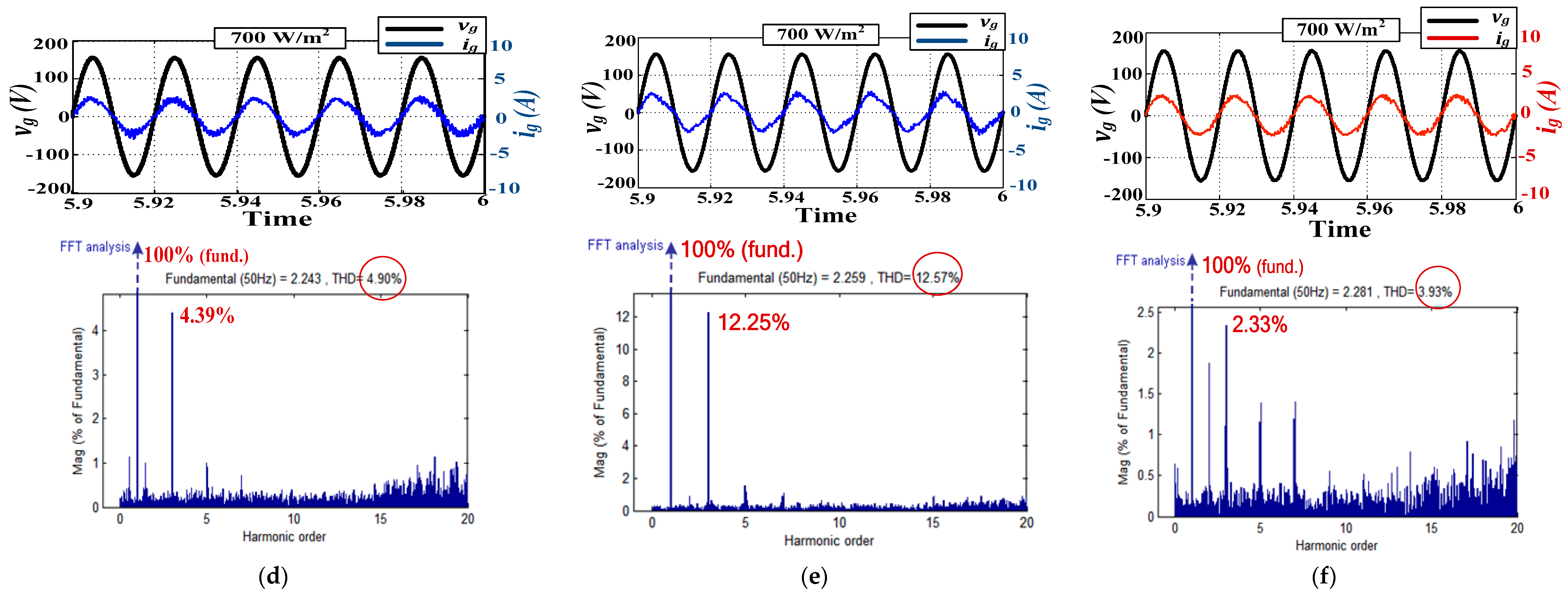
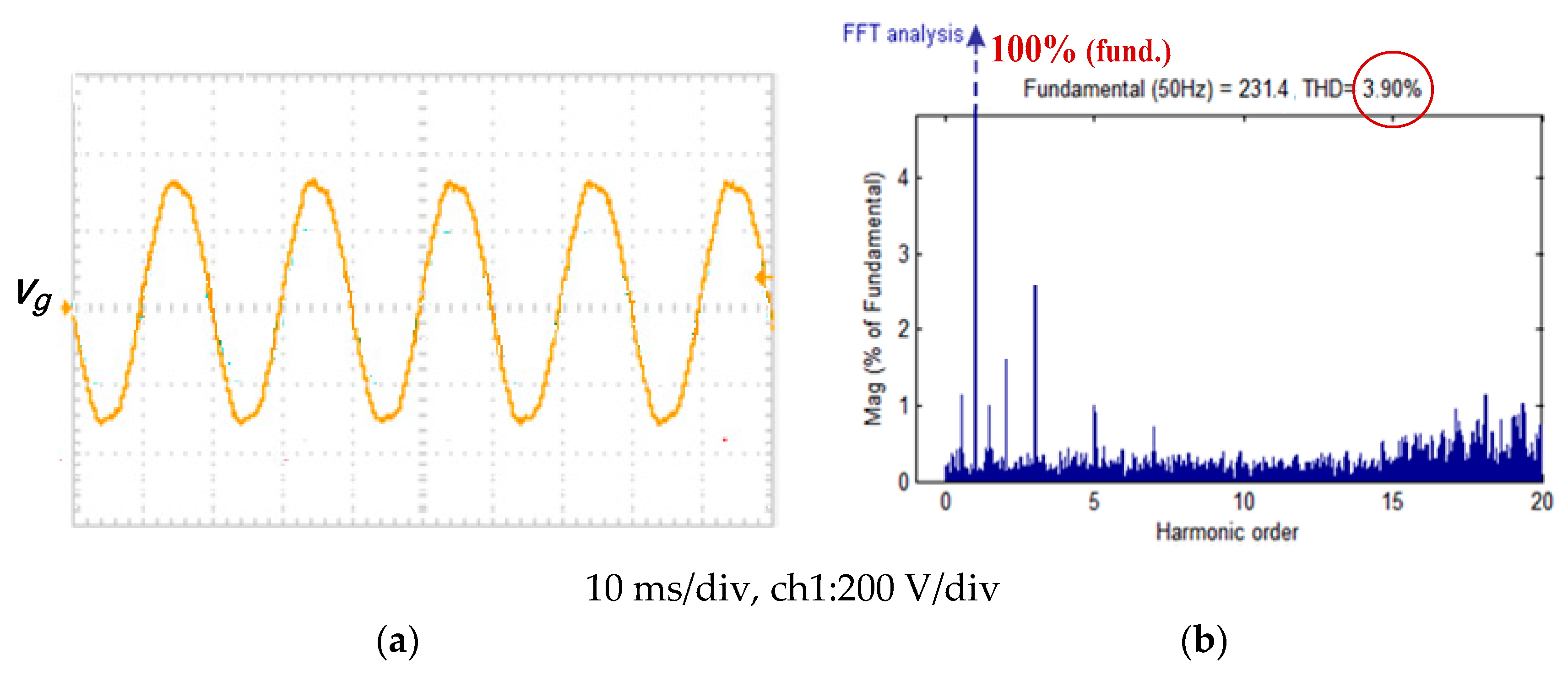
| Grid voltage | 220 V single phase pure sinusoidal supply | 220 V single phase near-sinusoidal supply at IEEE519 Std. distortion level THD = 3.9% |
| Grid frequency | 50 Hz | |
| Output filter Capacitance | 25 µF | |
| Output filter Inductance | 5 mH | |
| Switching frequency | 15 KHz | |
| PV panel | 285 W PV panel ASE-285-DGF/17 MODULE | Low-cost PV emulator |
References
- Guerrero, J.M.; Blaabjerg, F.; Zhelev, T.; Hemmes, K.; Monmasson, E.; Jemei, S.; Comech, M.P.; Granadino, R.; Frau, J.I. Distributed generation: Toward a new energy paradigm. IEEE Ind. Electron. Mag. 2010, 4, 52–64. [Google Scholar] [CrossRef]
- Liserre, M.; Sauter, T.; Hung, J.Y. Future energy systems: Integrating renewable energy sources into the smart power grid through industrial electronics. IEEE Ind. Electron. Mag. 2010, 4, 18–37. [Google Scholar] [CrossRef]
- Gonzalez, R.; Lopez, J.; Sanchis, P.; Marroyo, L. Transformerless inverter for single-phase photovoltaic systems. IEEE Trans. Power Electron. 2007, 22, 693–697. [Google Scholar] [CrossRef]
- National Renewable Energy Laboratory (NREL). Energy Analysis: Solar Power and the Electric Grid; National Renewable Energy Laboratory: Golden, CO, USA, 2010.
- Kouro, S.; Leon, J.I.; Vinnikov, D.; Franquelo, L.G. Grid-connected photovoltaic systems: An overview of recent research and emerging PV converter technology. IEEE Ind. Electron. Mag. 2015, 9, 47–61. [Google Scholar] [CrossRef]
- Romero-Cadaval, E.; Francois, B.; Malinowski, M.; Qing-Chang, Z. Grid-connected photovoltaic plants: An alternative energy source, replacing conventional sources. IEEE Ind. Electron. Mag. 2015, 9, 18–32. [Google Scholar] [CrossRef]
- Kjaer, S.B.; Pedersen, J.K.; Blaabjerg, F. A review of single-phase grid-connected inverters for photovoltaic modules. IEEE Trans. Ind. Appl. 2005, 41, 1292–1306. [Google Scholar] [CrossRef]
- Romero-Cadaval, E.; Spagnuolo, G.; Franquelo, L.G.; Ramos-Paja, C.A.; Suntio, T.; Xiao, W.M. Grid-connected photovoltaic generation plants: Components and operation. IEEE Ind. Electron. Mag. 2013, 7, 6–20. [Google Scholar] [CrossRef] [Green Version]
- Xiao, W.; Ozog, N.; Dunford, W. Topology study of photovoltaic interface for maximum power point tracking. IEEE Trans. Ind. Electron. 2007, 54, 1696–1704. [Google Scholar] [CrossRef]
- Roman, E.; Alonso, R.; Ibanez, P.; Elorduizapatarietxe, S.; Goitia, D. Intelligent PV module for grid-connected PV systems. IEEE Trans. Ind. Electron. 2006, 53, 1066–1073. [Google Scholar] [CrossRef]
- Chowdhury, S.; Chowdhury, S.P.; Crossley, P. Microgrids and Active Distribution Networks; IET Renewable Energy Series 6; Institution of Engineering and Technology: London, UK, 2009. [Google Scholar]
- Blaabjerg, F.; Teodorescu, R.; Liserre, M.; Timbus, A.V. Overview of control and grid synchronization for distributed power generation systems. IEEE Trans. Ind. Electron. 2006, 53, 1398–1409. [Google Scholar] [CrossRef] [Green Version]
- Eltawil, M.A.; Zhao, Z. Grid-connected photovoltaic power systems: Technical and potential problems—A review. Renew. Sustain. Energy Rev. 2010, 14, 112–129. [Google Scholar] [CrossRef]
- Shimizu, T.; Wada, K.; Nakamura, N. Flyback-type single-phase utility interactive inverter with power pulsation decoupling on the dc input for an ac photovoltaic module system. IEEE Trans. Power Electron. 2006, 21, 1264–1272. [Google Scholar] [CrossRef]
- Hu, H.; Harb, S.; Kutkut, N.; Batarseh, I.; Shen, Z.J. A review of power decoupling techniques for micro inverters with three different decoupling capacitor locations in PV systems. IEEE Trans. Power Electron. 2013, 28, 2711–2726. [Google Scholar] [CrossRef]
- Jain, S.; Agarwal, V. A single-stage grid connected inverter topology for solar PV systems with maximum power point tracking. IEEE Trans. Power Electron. 2007, 22, 1928–1940. [Google Scholar] [CrossRef] [Green Version]
- Wu, T.; Chang, C.; Lin, L.; Kuo, C. Power loss comparison of single- and two-stage grid-connected photovoltaic systems. IEEE Trans. Energy Convers. 2011, 26, 707–715. [Google Scholar] [CrossRef]
- Jain, S.; Agarwal, V. Comparison of the performance of maximum power point tracking schemes applied to single-stage grid-connected photovoltaic systems. IET Electr. Power Appl. 2007, 1, 753–762. [Google Scholar] [CrossRef]
- Chen, Y.M.; Chang, C.H.; Wu, H.C. DC-Link capacitor selections for the single-phase grid-connected PV system. In Proceedings of the 2009 International Conference on Power Electronics and Drive Systems (PEDS), Taipei, Taiwan, 2–5 November 2009; pp. 72–77. [Google Scholar]
- Hirachi, K.; Ishitobi, M.; Matsumoto, K.; Hatton, H.; Ishibashi, M.; Nakaoka, M.; Takahashi, N.; Kato, Y. Pulse area modulation control implementation for single-phase current source-fed inverter for solar photovoltaic power conditioner. In Proceedings of the IEEE Power Electronic Drives and Energy Systems for Industrial Growth Conference, Perth, Australia, 1–3 December 1998; pp. 677–682. [Google Scholar]
- Li, R.T.H.; Chung, H.S.H.; Chan, T.K.M. An active modulation technique for single-phase grid-connected CSI. IEEE Trans. Power Electron. 2007, 22, 1373–1382. [Google Scholar] [CrossRef]
- Patel, H.; Agarwal, V. A Single-Stage Single-Phase Transformer-Less Doubly Grounded Grid-Connected PV Interface. IEEE Trans. Energy Convers. 2009, 24, 93–101. [Google Scholar] [CrossRef]
- Ertasgin, G.; Whaley, D.M.; Ertugrul, N.; Soong, W.L. Analysis and design of energy storage for current-source 1-ph grid-connected PV inverters. In Proceedings of the IEEE Applied Power Electronics Conference and Exposition (APEC 2008), Austin, TX, USA, 24–28 February 2008; pp. 1229–1234. [Google Scholar]
- Komurcugil, H. Steady-state analysis and passivity-based control of single-phase PWM current-source inverters. IEEE Trans. Ind. Electron. 2010, 57, 1026–1030. [Google Scholar] [CrossRef]
- Darwish, A.; Abdelsalam, A.K.; Massoud, A.M.; Ahmed, S. Single phase grid connected current source inverter: Mitigation of oscillating power effect on the grid current. In Proceedings of the IET Conference on Renewable Power Generation, Edinburgh, UK, 6–8 September 2011; pp. 1–7. [Google Scholar]
- Alajmi, B.N.; Ahmed, K.H.; Adam, G.P.; Williams, B.W. Single-phase single-stage transformer less grid-connected PV system. IEEE Trans. Power Electron. 2013, 28, 2664–2676. [Google Scholar] [CrossRef]
- Ohnuma, Y.; Orikawa, K.; Itoh, J. A single-phase current-source PV inverter with power decoupling capability using an active buffer. IEEE Trans. Ind. Appl. 2015, 51, 531–538. [Google Scholar] [CrossRef]
- Wu, B. High-Power Converters and AC Drives Handbook; John Wiley & Sons, Inc.: Hoboken, NJ, USA, 2006. [Google Scholar]
- Wiechmann, E.P.; Aqueveque, P.; Burgos, R.; Rodríguez, J. On the efficiency of voltage source and current source inverters for high-power drives. IEEE Trans. Ind. Electron. 2008, 55, 1771–1782. [Google Scholar] [CrossRef]
- Abdelsalam, A.K.; Massoud, A.; Darwish, A.; Ahmed, S. Simplified generic on-line PWM technique for single phase grid connected current source inverters. In Proceedings of the IEEE Applied Power Electronics Conference and Exposition (APEC 2012), Orlando, FL, USA, 5–9 February 2012; pp. 1398–1403. [Google Scholar]
- Rashid, M.H. Power Electronics Handbook; Butterworth-Hinemann: Oxford, UK, 2011. [Google Scholar]
- Araújo, S.V.; Zacharias, P.; Mallwitz, R. Highly efficient single-phase transformerless inverters for grid-connected photovoltaic systems. IEEE Trans. Ind. Electron. 2010, 57, 3118–3128. [Google Scholar] [CrossRef]
- Hohm, D.P.; Ropp, M.E. Comparative study of maximum power point tracking algorithms. Prog. Photovolt. Res. Appl. 2003, 11, 47–62. [Google Scholar] [CrossRef]
- Esram, T.; Chapman, P.L. Comparison of photovoltaic array maximum power point tracking techniques. IEEE Trans. Energy Convers. 2007, 22, 439–449. [Google Scholar] [CrossRef] [Green Version]
- Spiazzi, G.; Buso, S.; Mattavelli, P.; Tenti, P. Low complexity MPPT techniques for PV module converters. In Proceedings of the International Power Electronics Conference, Sapporo, Japan, 21–24 June 2010; pp. 2074–2081. [Google Scholar]
- Liu, F.; Duan, S.; Liu, F.; Liu, B.; Kang, Y. A variable step size INC MPPT method for PV systems. IEEE Trans. Ind. Electron. 2008, 55, 2622–2628. [Google Scholar]
- Mei, Q.; Shan, M.; Liu, L.; Guerrero, J.M. A novel improved variable step-size incremental- resistance MPPT method for PV systems. IEEE Trans. Ind. Electron. 2011, 58, 2427–2434. [Google Scholar] [CrossRef]
- Zakzouk, N.E.; Abdelsalam, A.K.; Helal, A.A.; Williams, B.W. Modified variable-step incremental conductance maximum power point tracking technique for photovoltaic systems. In Proceedings of the IEEE Industrial Electronics Society Conference (IECON 2013), Vienna, Austria, 10–13 November 2013; pp. 1741–1748. [Google Scholar]
- Ninad, N.A.; Lopes, L.A.C. Operation of single-phase grid-connected inverters with large DC bus voltage ripple. In Proceedings of the IEEE Electrical Power Conference (EPC 2007), Montreal, QC, Canada, 25–26 October 2007; pp. 172–176. [Google Scholar]
- Wai, R.J.; Wang, W.H. Grid-connected photovoltaic generation system. IEEE Trans. Circuits Syst. 2008, 55, 953–964. [Google Scholar]
- Ciobotaru, M.; Teodorescu, R.; Blaabjerg, F. Control of single-stage single-phase PV inverter. In Proceedings of the IEEE European Power Electronics and Applications Conference (EPE), Dresden, Germany, 11–14 September 2005; pp. 1–10. [Google Scholar]
- Zammit, D.; Staines, C.S.; Apap, M. Comparison between PI and PR current controllers in grid connected PV inverters. Int. J. Electr. Robot. Electron. Commun. Eng. 2014, 8, 217–222. [Google Scholar]
- Fukuda, S.; Yoda, T. A novel current-tracking method for active filters based on a sinusoidal internal model. IEEE Trans. Ind. Electron. 2001, 37, 888–895. [Google Scholar] [CrossRef] [Green Version]
- Yuan, X.; Merk, W.; Stemmler, H.; Allmeling, J. Stationary-frame generalized integrators for current control of active power filters with zero steady-state error for current harmonics of concern under unbalanced and distorted operating conditions. IEEE Trans. Ind. Appl. 2002, 38, 523–532. [Google Scholar] [CrossRef]
- Mastromauro, R.A.; Liserre, M.; Aquila, A.D. Control issues in single-stage photovoltaic systems: MPPT, current and voltage control. IEEE Trans. Ind. Inform. 2012, 8, 241–254. [Google Scholar] [CrossRef]
- Teodorescu, R.; Blaabjerg, F.; Liserre, M.; Loh, P.C. Proportional-resonant controllers and filters for grid connected voltage-source converters. IEE Proc. Electr. Power Appl. 2006, 153, 750–762. [Google Scholar] [CrossRef] [Green Version]
- Kulkarni, A.; John, V. Mitigation of lower order harmonics in a grid-connected single-phase PV inverter. IEEE Trans. Power Electron. 2013, 28, 5024–5037. [Google Scholar] [CrossRef]
- Chattopadhyay, R.; De, A.; Bhattacharya, S. Comparison of PR controller and damped PR controller for grid current control of LCL filter based grid-tied inverter under frequency variation and grid distortion. In Proceedings of the IEEE Energy Conversion Congress and Exposition (ECCE), Pittsburgh, PA, USA, 14–18 September 2014; pp. 3634–3641. [Google Scholar]
- Castilla, M.; Miret, J.; Matas, J.; de Vicuña, L.G.; Guerrero, J.M. Control design guidelines for single-phase grid-connected photovoltaic inverters with damped resonant harmonic compensators. IEEE Trans. Ind. Electron. 2009, 56, 4492–4501. [Google Scholar] [CrossRef]
- Castilla, M.; Miret, J.; Camacho, A.; Matas, J.; de Vicuña, L.G. Reduction of current harmonic distortion in three-phase grid-connected photovoltaic inverters via resonant current control. IEEE Trans. Ind. Electron. 2013, 60, 1464–1471. [Google Scholar] [CrossRef]
- Teodorescu, R.; Blaabjerg, F. Proportional-resonant controllers. A new breed of controllers suitable for grid-connected voltage-source converters. Proc. Optim. 2004, 3, 9–14. [Google Scholar]
- de Araujo, M.B.; Rocha, L.R.; Martins, L.T.; Vieira, R.P. Multiloop Current Control Strategy for a Grid-connected VSI with LCL Filter Using Backstepping and Proportional+Resonant Controller. In Proceedings of the 2019 IEEE PES Innovative Smart Grid Technologies Conference, Gramado, Brazil, 15–18 September 2019; pp. 1–6. [Google Scholar]
- Teodorescu, R.; Blaabjerg, F.; Borup, U.; Liserre, M. A new control structure for grid-connected LCL PV inverters with zero steady-state error and selective harmonic compensation. In Proceedings of the IEEE Applied Power Electronics Conference and Exposition (APEC 2004), Anaheim, CA, USA, 22–26 February 2004; pp. 580–589. [Google Scholar]
- Ciobotaru, M.; Kerekes, T.; Teodorescu, R.; Bouscayrol, A. PV inverter simulation using MATLAB/Simulink graphical environment and PLECS blockset. In Proceedings of the IEEE Industrial Electronics Conference (IECON2006), Paris, France, 6–10 November 2006; pp. 5313–5318. [Google Scholar]
- Timbus, A.; Liserre, M.; Teodorescu, R.; Rodriguez, P.; Blaabjerg, F. Evaluation of current controllers for distributed power generation systems. IEEE Trans. Power Electron. 2009, 24, 654–662. [Google Scholar] [CrossRef]
- IEEE. IEEE Recommended Practice and Requirements for Harmonic Control in Electric Power Systems; IEEE: New York, NY, USA, 1993. [Google Scholar]
- Mukerjee, A.K.; Dasgupta, N. DC power supply used as photovoltaic simulator for testing MPPT algorithms. Renew. Energy 2006, 32, 587–592. [Google Scholar] [CrossRef]
- IEEE. IEEE Recommended Practice and Requirements for Harmonic Control in Electric Power Systems; IEEE: New York, NY, USA, 2014. [Google Scholar]
- Zakzouk, N.E.; Abdelsalam, A.K.; Helal, A.A.; Williams, B.W. PV single-phase grid-connected converter: DC-link voltage sensorless prospective. IEEE J. Emerg. Sel. Top. Power Electron. 2017, 5, 526–546. [Google Scholar] [CrossRef] [Green Version]
- Zakzouk, N.E.; Khamis, A.K.; Abdelsalam, A.K.; Williams, B.W. Continuous-input continuous-output current buck-boost DC/DC converters for renewable energy applications: Modelling and performance assessment. Energies 2019, 12, 2208. [Google Scholar] [CrossRef] [Green Version]


| Nominal short circuit current (ISCn) | 18.4 | A |
| Nominal open circuit voltage (VOCn) | 20 | V |
| Maximum power current (IMPP) | 16.8 | A |
| Maximum power voltage (VMPP) | 17 | V |
| Maximum output power (Pmax) | 285 | W |
| Current/temp. coefficient (Ki) | 18.4 × 10⁻³ | A/°C |
| Voltage/temp. coefficient (Kv) | −7.6 × 10⁻² | V/°C |
| Series cells | 216 | - |
| 150 mH, for = 0.33 A, and 50 mH, for = 1 A | |
| 25 µF and 5 mH for fs = 15 kHz |
| Case | Irradiance | Settling Time, (s) | PV Power, (W) | Grid Power, (W) | Overall Efficiency |
|---|---|---|---|---|---|
| Ldc = 150 mH CPRC | 1000 W/m2 | 0.185 | 284.8 | 245 | 86% |
| 700 W/m2 | 0.025 | 195 | 174 | 89% | |
| Ldc = 50 mH CPRC | 1000 W/m2 | 0.055 | 282 | 260 | 92% |
| 700 W/m2 | 0.015 | 186 | 175 | 94% | |
| Ldc = 50 mH PCHC | 1000 W/m2 | 0.055 | 282.5 | 260 | 92% |
| 700 W/m2 | 0.015 | 188 | 177 | 94% |
| ζOVERALL | ζconv. | ζMPPT. | |
|---|---|---|---|
| CPRC at 150 mH | 86% | 90% | 95% |
| CPRC at 50 mH | 92% | 97% | 94% |
| PCHC at 50 mH | 92% | 97% | 94% |
© 2020 by the authors. Licensee MDPI, Basel, Switzerland. This article is an open access article distributed under the terms and conditions of the Creative Commons Attribution (CC BY) license (http://creativecommons.org/licenses/by/4.0/).
Share and Cite
Zakzouk, N.E.; Abdelsalam, A.K.; Helal, A.A.; Williams, B.W. High Performance Single-Phase Single-Stage Grid-Tied PV Current Source Inverter Using Cascaded Harmonic Compensators. Energies 2020, 13, 380. https://0-doi-org.brum.beds.ac.uk/10.3390/en13020380
Zakzouk NE, Abdelsalam AK, Helal AA, Williams BW. High Performance Single-Phase Single-Stage Grid-Tied PV Current Source Inverter Using Cascaded Harmonic Compensators. Energies. 2020; 13(2):380. https://0-doi-org.brum.beds.ac.uk/10.3390/en13020380
Chicago/Turabian StyleZakzouk, Nahla E., Ahmed K. Abdelsalam, Ahmed A. Helal, and Barry W. Williams. 2020. "High Performance Single-Phase Single-Stage Grid-Tied PV Current Source Inverter Using Cascaded Harmonic Compensators" Energies 13, no. 2: 380. https://0-doi-org.brum.beds.ac.uk/10.3390/en13020380