Fuel Conservation for Launch Vehicles: Falcon Heavy Case Study

1
Faculty of Natural Sciences and Mathematics, Physics Department, University of Maribor, Koroška cesta 160, SI-2000 Maribor, Slovenia
2
Jožef Stefan International Postgraduate School, Jamova cesta 39, SI-1000 Ljubljana, Slovenia
3
Jožef Stefan Institute, Jamova cesta 39, SI-1000 Ljubljana, Slovenia
4
Association for Technical Culture of Slovenia, Zaloška cesta 65, 1000 Ljubljana, Slovenia
*
Author to whom correspondence should be addressed.
Energies 2020, 13(3), 660; https://0-doi-org.brum.beds.ac.uk/10.3390/en13030660
Submission received: 3 January 2020
/
Revised: 23 January 2020
/
Accepted: 31 January 2020
/
Published: 4 February 2020
(This article belongs to the Special Issue Selected Papers from SDEWES 2019 conferences on Sustainable Development of Energy, Water and Environment Systems)
Abstract
:Space exploration has recently been growing at an increasing pace and has caused a significant burden to the environment, in particular, during the launch of rockets, when a large amount of fuel is burned and the exhaust gases are released in the air. For this case study, we selected the SpaceX Falcon Heavy reusable heavy-lift launch vehicle, which is one of the most promising rockets for the low-cost lifting of heavy payloads into orbit and beyond. We evaluated several strategies for optimisation of fuel consumption and for minimisation of environmental impact during launch through the atmosphere for the case of its first launch on February 6, 2018, when the rocket carried a red Tesla Roadster with a “Starman” in the direction toward Mars. In addition to the flight plan and Newtonian equations of motion, we have taken into account the thermodynamic properties of the rocket engines. Results are similar but slightly different if one minimises the total fuel consumption for the desired flight plan or if one minimises the environmental pollution during the initial stage of the launch through the atmosphere. The same methodology can be extended for launches in other directions including the Earth orbit and the Moon.
1. Introduction
The first rocket flights into space began in the 1940s with the German V-2 rocket, which reached 85 km in 1942 and 174 km in 1944 [1]. On October 4, 1957, the first artificial satellite, Sputnik 1, was launched into orbit by the Russians with an R-7 rocket. In July 1969, the Americans used a Saturn V rocket to send Neil Armstrong and Buzz Aldrin into space [2]. The high price of rocket flights has been an important limiting factor in the exploration of space. Many strategies have therefore been designed to reduce the price of rocket flights. With the vision of reducing the costs of space flight and reaching other planets (especially Mars), Elon Musk founded SpaceX in 2002 [3]. SpaceX developed the Falcon rocket family and became the first private company to launch a rocket into Earth’s orbit with the Falcon 1 rocket. They are also the first company to successfully return a rocket launched into low Earth orbit to Earth. Today, the Falcon 9 rocket is already a regular provider of space-to-air flights, most notably satellites into Earth orbit and cargo transport to the International Space Station. Their current largest Falcon Heavy rocket is capable of lifting twice as much cargo into Earth’s orbit as the Delta IV Heavy (the world’s second most powerful operating rocket) for only a third of the price. The only rocket that could carry more cargo into orbit than the Falcon Heavy is the Saturn V moon, which last flew in 1973 [4].
The aim of this study is to find strategies that would allow the reduction of fuel consumption when flying a Falcon Heavy rocket, and to estimate, how much fuel could be saved in each flight. In this way, the price of the flight would decrease, and the environmental impact would also be reduced.
In recent history of rocket flights, many different approaches to energy savings have been tested. Most of these approaches were described by Sutton and Biblarz [5]. They deal with different types of propellants, combustion chamber and nozzle designs and materials. They also analyze the combustion chamber and motor case conditions, the nozzle expansion process, engine systems and their control. In this way, their analysis represents the current state-of-the-art for performance of rocket propulsion systems.
Some additional ideas include simulations of rocket engines in order to improve their efficiency [6], search for a better fuel mixture which would allow for a higher exhaust fuel velocity and a higher specific impulse [7], and numerical modelling of the combustion of fuel in the rocket, which can be performed with very high accuracy [8]. It is, however, not simple to obtain significant fuel savings using these approaches.
In this study, we attempted to further optimize the flight trajectory, so that the rocket could gain the same energy during launch with less fuel. The expected reduction of price of rocket launches would have a positive impact on future exploration of space as well as on commercial applications of space such as the production of energy in space for use on Earth [9,10]. In addition, this type of modeling is applicable also in physics education for learning the process of modeling.
2. Falcon Heavy Rocket
The Falcon Heavy is a 70-meter-tall SpaceX rocket that weighs about 1420 tons at take-off [11]. It is the largest rocket from the Falcon family and, at the same time, the most powerful operating rocket in the world. It is capable of lifting 54 tons of cargo into low-Earth orbit, far higher than the Falcon 9 (the second largest rocket of the Falcon family) capable of lifting 13 tons of cargo into low-Earth orbit. It is roughly made up of three parts: zero, first and second stages.
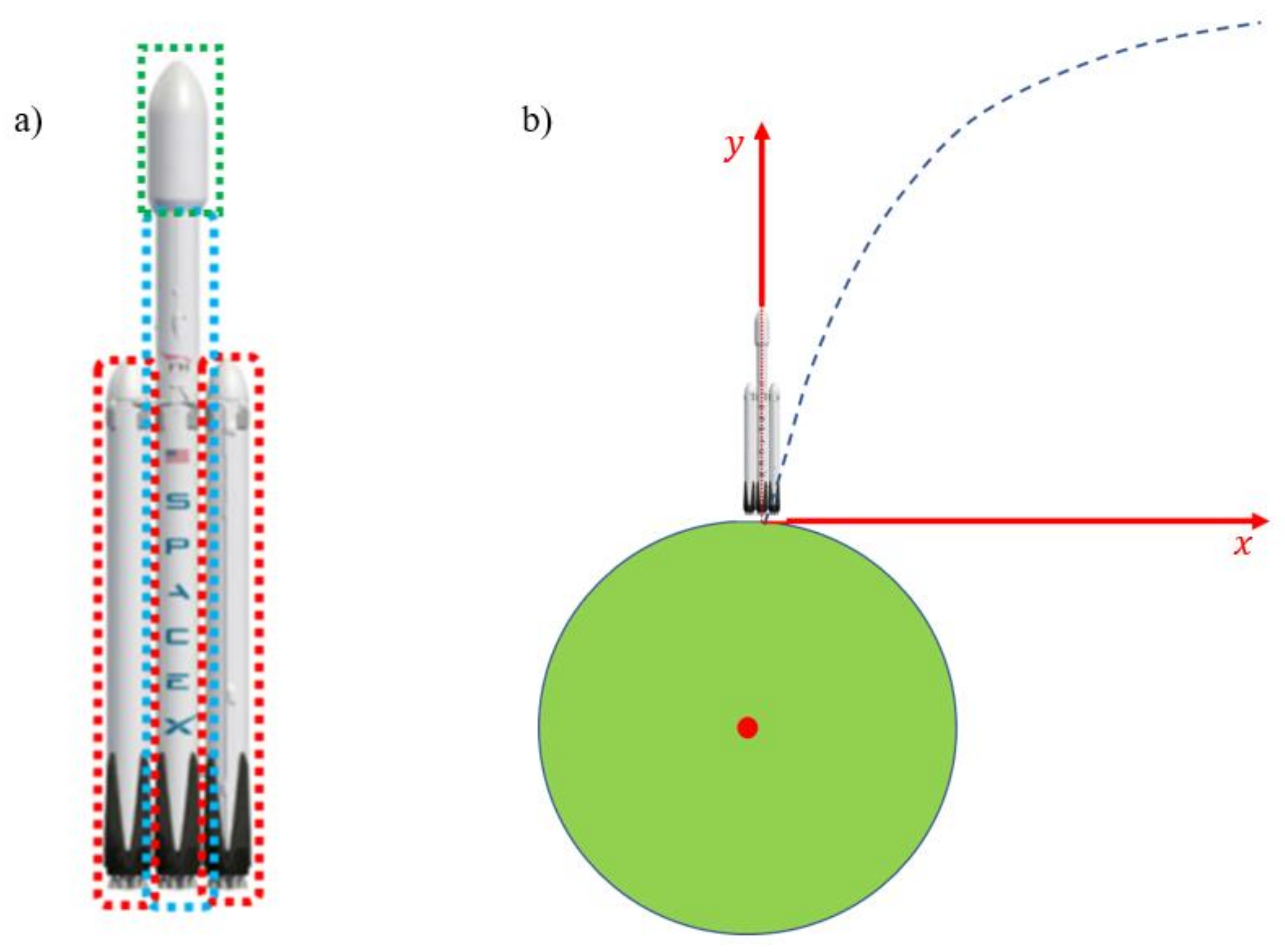
The zero stage of the rocket is represented by two side boosters and is indicated by a red dashed line in Figure 1a. Each thruster contains nine Merlin 1D engines, an empty one weighing about 17 tons and a capacity of 407.6 tons of fuel. The first stage of the rocket is indicated by a blue dashed line in Figure 1a and represents the center core of the rocket. The first stage also has nine Merlin 1D engines, an empty one weighing about 17 tons and room for 407.6 tons of fuel. In this paper, we refer to the entire first stage as the main engine. The second stage is the capsule at the top of the rocket, indicated by the green line in Figure 1a. It has one Merlin 1D Vac engine, the empty one weighs 4.5 tons, and holds 107.2 tons of fuel. A total of 1330 tons of fuel goes into the entire rocket.
The fuel used by the Falcon Heavy rocket is RP-1 (Rocket Propellant-1 or Refined Petroleum-1) and is a type of kerosene. For combustion it also uses LOX (liquid oxygen), which serves as an oxidizer without which there would be no combustion. They mix in a ratio of RP1: LOX = 1: 2.33 [12], and the price of the mix is about $ 0.48 per kilogram [13]. The Falcon Heavy rocket test flight was conducted on February 6, 2018 from Florida [14]. For this flight, it was possible to obtain the position, velocity and acceleration data of the rocket and the dynamic pressure on the rocket from the test flight telemetry [15]. The user who posted the data on the reddit.com portal obtained this information from a live flight download using a program from the Github source [16].
Figure 1b shows the coordinate system used with the model. The starting point is at the point where they launch the rocket. The red dot inside the Earth represents its mass center. The blue dashed line approximates the flight path. All the rocket specifications used with the model are shown in Table 1.
3. Modelling of the Falcon Heavy flight
The computational model for the determination of the time dependence of rocket mass and mass flow was developed within the diploma seminar [17], which was presented at [18]. The flight data were obtained from the test flight telemetry [15]. The fuel consumed was observed in terms of the specific impulse (), for each rocket stage at sea level and in vacuum and the fuel speed relative to the rocket () is obtained from the equation
where is the gravity acceleration on the Earth’s surface. Equation (1) is obtained by the following consideration. Fuel thrust force () equals to
where is the mass flow rate of the rocket fuel and is equal to the mass of fuel () thrown by the rocket at the time interval following the equation
This leads to
The specific impulse is calculated as
As the specific impulse changes with altitude, consequently the speed of the fuel also depends on the altitude. For the specific impulse data was available at sea level and in vacuum. In between, the specific impulse was interpolated in proportion to the density of the air. The air density (ρ) dependence on the altitude was obtained from the test flight telemetry [15] data on dynamic pressure (q) as
where u is the velocity of the air relative to the rocket, which is the same as the relative velocity of the rocket (vr) as obtained from the telemetry data [15].
Our model split the flight into three sections. In the first part, both the side thrusters and the main engine operate. The side thrusters are considered together as one engine. The ratio (μ) between how much fuel per time unit the side thrusters consumed together and how much fuel per time unit both the thrusters and the main engine consumed at some point was 0.717. This ratio was chosen so that the tanks of the individual stages were emptied at the same time as they were emptied in real flight. The rocket then discards the side thrusters and follows the second part of the flight when only the main engine is lit. When the main engine tank is emptied, the rocket discards it. The third part of the flight follows, when the rocket has a second stage. At that time, the rocket was far from the Earth’s atmosphere, so the rocket speed () of the rocket was constant. In the first and second parts, however, the fuel speed is height dependent (indicated by ).
The model was solved numerically with the Euler method with the time step of one second using the empirical data from the Falcon Heavy Test Flight Telemetry [15]. Inside the loop, at each step the x and y components of () and () were calculated. In addition to these two forces, the reaction thrust force was exerted on the rocket by the fuel escaping from the rocket (), which was calculated using the Newton law of motion from the expression
where is the instantaneous mass of the rocket and the instantaneous acceleration of the rocket. First the mass flow rate of the rocket fuel was calculated, and consequently the amount of fuel the rocket consumed from each tank and the components of the thrust force .
The drag depends on the rocket speed quadratically and on the density of air, which is the largest at the sea level and decreases fast with height. Although the drag force during the launch can be quite significant, it is even at the highest level in the early part of the launch still about two orders of magnitude small. Since the drag decreases fast with height, for most of the flight it is negligible. The reduction of the drag force would therefore contribute only a very small part to the energy savings which is estimated to less than 0.1%.
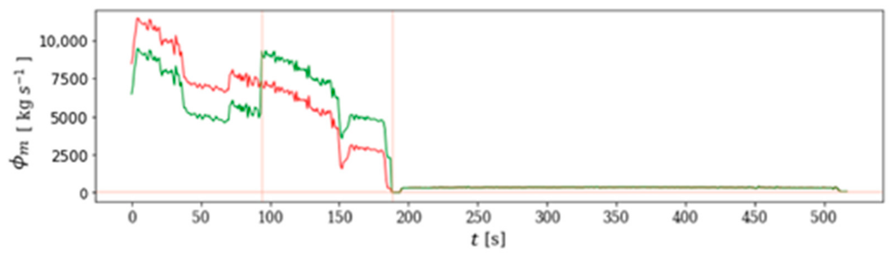
As the strategy to save fuel, the time interval was split from the start of the flight to the time when the rocket dropped the main engine into two equal lengths. In order to monitor how the time dependence of the mass flow of fuel on the total energy of the rocket affects, in the first half the mass flow was changed, and in the second half the mass flow was changed in the other direction, so that the total fuel mass consumed did not change (panel below the graph). A parameter λ was introduced as a measure for the change in the mass flow in each of the described two parts of the flight. Vhe λ value was varied from −7000 kg/s to 2000 kg/s in 100 kg/s increments. At each step, the rocket flight was simulated and the total energy after the end of the observed flight calculated. An example graph of the model time dependence of the rocket mass flow rate (green curve) versus the real graph (red curve) is shown in Figure 2. The result of this part of the program is a graph in Figure 3 showing the dependence of the rocket’s end energy divided by the rocket’s final energy at real flight on the value of λ and the dependence of the maximum resistance force on the value of λ.
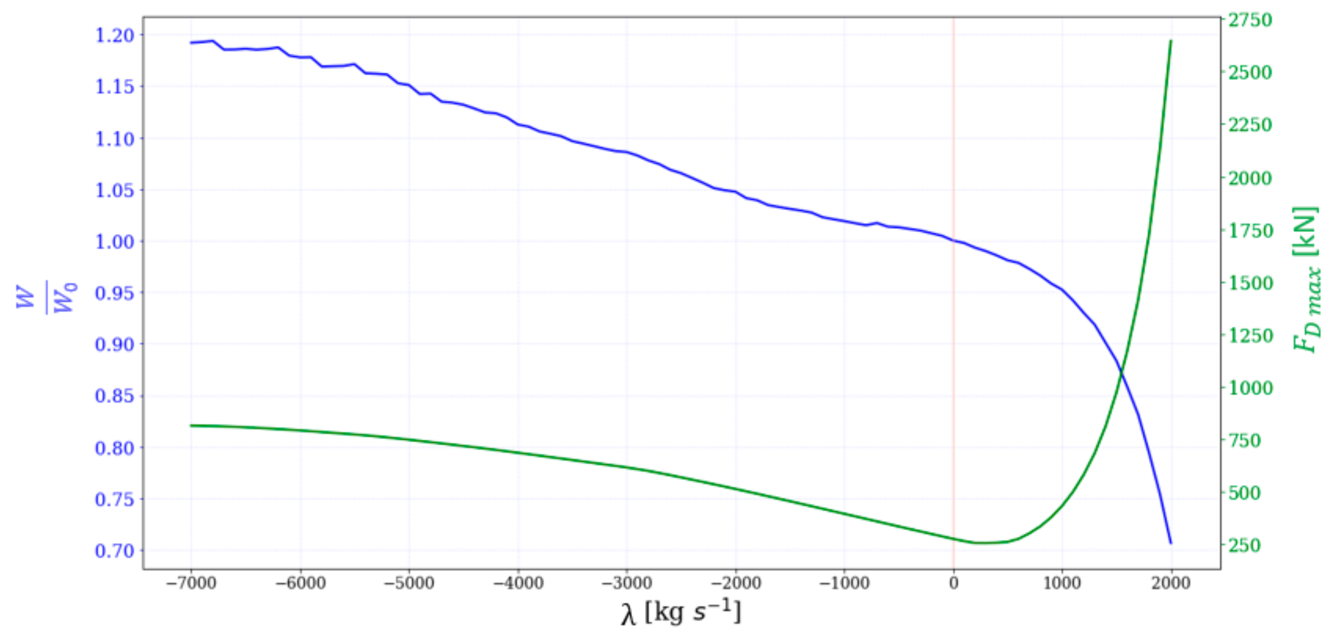
Figure 3 shows that in the presented range the total energy decreases with increasing value of λ. The maximum resistance force decreases with decreasing λ, decreases with increasing value λ for a while, and then starts to rise sharply. The reason for the steep increase in the maximum resistance force at increasing λ is that the rocket has a lower mass flow of fuel at the beginning of flight and therefore accelerates more slowly and is still very low at the time of the left red line in Figure 2. Then it starts to accelerate greatly because the mass flow is suddenly greatly increased. However, since the rocket is low at the time, the air there is denser and, with the high speed of the rocket, the resulting resistance to the rocket is much greater.
In order to reduce fuel consumption (or increase the final total energy), we conclude that λ must be as small as possible (greater negative values). At lower λ values, the mass flow rate at the beginning of the flight was higher than the original. From this, it follows that it is more advantageous from the energy point of view for the rocket to turn on the rocket engines at maximum power at the beginning of the flight, and then maintain this for as long as possible. At the same time, the maximum resistance force increases.
4. Optimal Time Dependence of the Mass Flow
The purpose of this study was to find such a flight trajectory that would yield the same final energy of the rocket with the least amount of fuel. We start from the rocket equation for a simplified case, which can be solved for velocity v as a function of time t as [19]:
where is the initial velocity and the initial mass of the rocket, m the current mass of the rocket and g0 the gravity acceleration. Our case is more complex, because the gravity acceleration decreases with height and the drag force further reduces the velocity. Nevertheless, the last term in Equation (8), which determines the time dependence, behaves similarly also in presence of drag, as long as it is not large. This means that long times of flight decrease the final velocity and thus also the final energy. It is therefore important to reduce the time of flight as much as possible.
The time of the flight will be shortest, if the rocket has the biggest possible mass flow at the beginning of the flight, so it moves away from Earth as soon as possible. This strategy was therefore selected for the model flight, which was evaluated numerically to verify the actual fuel savings. There are, however, two problems with this strategy. The first problem is that the higher the rocket mass flow rate, the higher the rocket velocity and the greater the drag force to the rocket. This on one hand dissipates energy, so that fuel is wasted, and on the other hand, the rocket could approach the maximum value of the drag force that the rocket can structurally withstand. The second problem is that an increase in the fuel flow rate also increases acceleration, which can become too high for flights with human crews. Namely, acceleration greater than 4 g0 is only possible for a few seconds for an average person before they faint, which can be followed by death [20]. Higher accelerations could only be sustained by trained individuals in special suits, so the rocket flights carrying human should be limited to accelerations of less than 4 g0.
Therefore the following constraints had to be used for the mass flow in the model flight: The mass flow was limited to the maximum mass flow rate from real flight and the value of the rocket drag force was also limited to the maximum value of the rocket resistance force of the original flight. In each step of the simulation this constraint was checked, and if the drag force was too high, the step would be repeated with a smaller value of the mass flow. We did not model the flights with human crew, however, for such flights the mass flow would also be limited by the maximum acceleration acceptable to humans, which should be less than 4 g0.
The determination of the maximum possible mass flow rate during the flight also depends on the number of rocket engines during each stage. In the first stage there are 27 engines, in the second stage 9 engines, and in the third stage 1 engine.
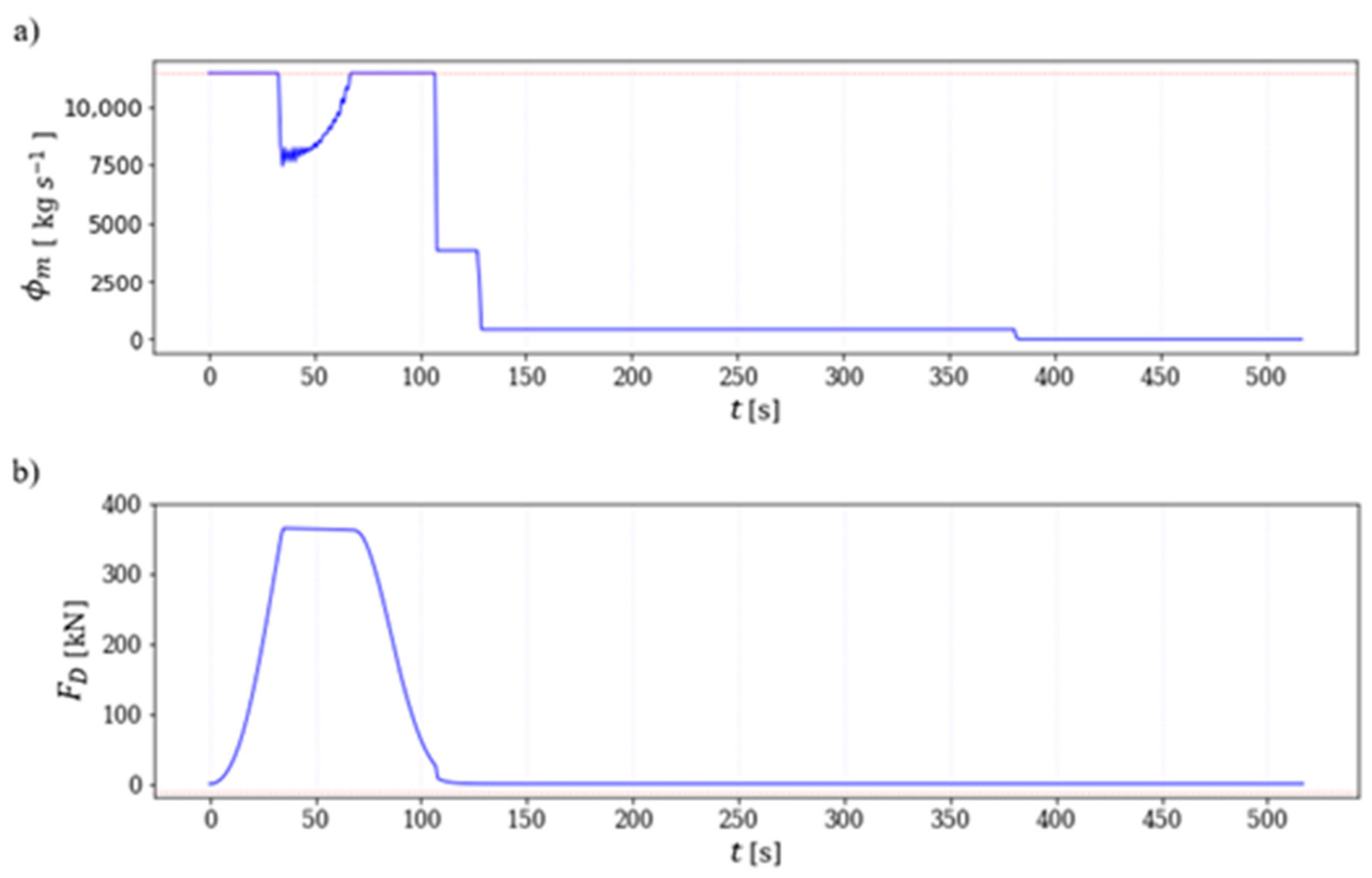
Based on the above described constraints, a model flight exhibiting the biggest possible mass flow at the beginning of the flight was simulated by solving Newton’s laws of motion numerically using the Euler method. The time dependences of and the drag force in this model flight are shown in Figure 4. The magnitude of decreased between 30 and 70 s because the drag force was then at its maximum permissible value and the rocket had to reduce its engine power.
5. Results and Discussion
Numerical solution of the model flight returned the flight trajectory in terms of position and velocity as a function of time. From this result, all the forces and the energy were evaluated for the complete model flight. After the end of the model flight, the total rocket energy was calculated and compared to the total rocket energy of the original flight. The time dependence of the total energy for each flight is shown in Figure 5, which shows that the rocket had a final total energy of about 1% greater for the model flight than in the real flight.
In order to calculate the fuel savings, we repeated the numerical simulations of the model flight with different reduced amounts of initial fuel.
One also has to answer the question, from which engine should the fuel be removed? Since the rocket first dumps the side thrusters and this reduces its weight, it is clear that the best fuel saving strategy is to reduce the amount of fuel in the side thrusters. In this way, the rocket could dump them as soon as possible when they run out of fuel.
In the calculation, the amount of fuel in the side thrusters was decreased in small steps, and then a flight simulation was performed again. At each step, the final total energy of the rocket was calculated. The dependence of the final energy on the amount of fuel saved was obtained from numerical calculations of the model flight with reduced amount of fuel is presented in Figure 6a. When the final total energy of the empty rocket in the model flight matches the final total energy in the real flight, the reduction of initial fuel mass m equals the fuel savings. Namely, if there were less fuel aboard, the rocket could not reach its final total energy, and if there were more fuel aboard, the rocket would be carrying unnecessary weight.
From the graph in Figure 6, it can be deduced that, in such a flight mode, the rocket could theoretically save about 35.5 tons of fuel, which is 2.7% of the total fuel of the original flight.
6. Conclusions
This study dealt with the flight of the Falcon Heavy rocket. Using a computational model, we simulated a real flight and obtained the time dependence of the mass flow rate of the rocket fuel (Figure 3b). The time dependence of the mass flow of fuel was then varied (Figure 2) to monitor how the time dependence of the mass flow of fuel affected the total energy of the rocket. In the first part of the flight, we reduced the mass flow of fuel by a certain value λ, and in the second part, we increased the mass flow by the same value λ so that the total mass consumed did not change. We obtained the dependence of the ultimate energy of the rocket on the value of λ (Figure 3). It follows that the lower (negative) values of λ are better from an energy point of view. By imposing a limit on the maximum value of the mass flow of fuel and the maximum value of the force of resistance on a rocket at the maximum value in real flight, we obtained the time dependence of the mass flow of fuel in Figure 4a. From the graph in Figure 5, we can read the difference of energies at the end of the real and model flight. The result in Figure 6b shows an estimate of the possible fuel savings required for a rocket flight, which is around 35.5 tons, or 2.7% of the total fuel of the original flight. Such a saving can be realized without any investment by only slightly changing the flight path of the rocket, and it can reduce both the cost of space flight and the environmental pollution from space flights, as less fuel would be burnt.
As the final result, the fuel savings of the rocket were estimated as obtained by only slightly changing the time dependence of the mass flow of fuel. This simple method has a significant potential to reduce the cost of space flight and also the environmental impact of burning fossil fuels during rocket launches. This fuel saving strategy could be used for any rocket and could have a major impact in the near future, in particular, in view of the fact that SpaceX plans to significantly increase space flights due to the desire to colonize Mars [21].
Author Contributions
Conceptualization, A.Z. and P.J.; methodology, A.Z. and P.J.; software, P.J.; validation, A.Z. and P.J.; investigation, P.J.; resources, P.J., A.Z. and R.R.; visualization, P.J.; supervision, A.Z.; project administration, A.Z.; funding acquisition, A.Z. and R.R. All authors have read and agreed to the published version of the manuscript.
Funding
Part of this research was supported by Slovenian Research Agency, grant numbers P2-0348 and P1-0403, and by the Republic of Slovenia and the European Social Fund within the project INOVUP.
Conflicts of Interest
The authors declare no conflict of interest.
References
- DeVorkin, D.H.; Neufeld, M.J. Space artifact of Nazi weapon? Displaying the Smitsonian’s V-2 missile, 1976-2011. Endeavour 2011, 35, 187–195. [Google Scholar] [CrossRef] [PubMed]
- Mancini, J. Now just four men who walked on the moon are still alive. 26 May 2018. Available online: https://qz.com/1290267/astronaut-alan-bean-fourth-man-to-walk-on-the-moon-is-dead/ (accessed on 30 July 2019).
- SpaceX. Available online: https://www.spacex.com/about (accessed on 30 July 2019).
- Falcon heavy. SpaceX. Available online: https://www.spacex.com/falcon-heavy (accessed on 30 July 2019).
- Sutton, G.P.; Biblarz, O. Rocket Propulsion Elements, 8th ed.; Wiley: Hoboken, NJ, USA, 2010; p. 784. [Google Scholar]
- Li, C.; Xia, Z.; Ma, L.; Zhao, X.; Chen, B. Numerical Study on the Solid Fuel Rocket Scramjet Combustor with Cavity. Energies 2019, 12, 1235. [Google Scholar]
- Anand, K.V.; Roy, A.; Mulla, I.; Balbudhe, K.; Jayaraman, K.; Chakravarthy, S.R. Experimental data and model predictions of aluminium agglomeration in ammonium perchlorate-based composite propellants including plateau-burning formulations. In Proceedings of the Combustion Institute, Princeton, NJ, USA, 23–28 June 2013; Elsevier: Amsterdam, The Netherlands; 34, pp. 2139–2146. [Google Scholar]
- Naderi, M.; Guozhu, L. Static performance modeling and simulation of the staged combustion cycle LPREs. Aerosp. Sci. Technol. 2019, 86, 30–46. [Google Scholar] [CrossRef]
- Lior, N. Power from space. Energy Convers. Manag. 2001, 42, 1769–1805. [Google Scholar] [CrossRef]
- Zidanšek, A.; Ambrožič, M.; Milfelner, M.; Blinc, R.; Lior, N. Solar orbital power: sustainability analysis. Energy 2011, 36, 1986–1995. [Google Scholar] [CrossRef]
- Space Launch Report. SpaceX Falcon Heavy. Available online: http://www.spacelaunchreport.com/falconH.html#config (accessed on 30 July 2019).
- Falcon Heavy. Spaceflight. Available online: http://spaceflight101.com/spacerockets/falcon-heavy/ (accessed on 30 July 2019).
- Hobbes, Kevinson, C. Stack Exchange, How much fuel does the Falcon Heavy use? What is the price RP-1?. Available online: https://space.stackexchange.com/questions/32729/how-much-fuel-does-the-falcon-heavy-use-what-is-the-price-rp-1 (accessed on 30 July 2019).
- Falcon Heavy Test Launch, SpaceX. Available online: https://www.spacex.com/news/2018/02/07/falcon-heavy-test-launch (accessed on 30 July 2019).
- Falcon Heavy Test Flight Telemetry. Reddit. Available online: https://www.reddit.com/r/spacex/comments/7vtap9/falcon_heavy_test_flight_telemetry/ (accessed on 30 July 2019).
- SpaceXtract. Github. Available online: https://github.com/shahar603/SpaceXtract/ (accessed on 30 July 2019).
- Jozič, P. Reduction in fuel consumption of the Falcon Heavy flight. BSc Diploma Seminar, University of Maribor, Maribor, Slovenia, 4 September 2019. [Google Scholar]
- Jozič, P.; Zidanšek, A.; Repnik, R. Energy optimisation for reusable heavy-lift launch vehicles. In Proceedings of the SDEWES 2019 14th Conference on Sustainable Development of Energy, Water and Environment Systems, Dubrovnik, Croatia, 1–6 October 2019. 0578–10578-6. [Google Scholar]
- Greitzer, E.M.; Spakovszky, Z.S.; Waitz, I.A. Thermodynamics and Propulsion, MIT Lecture Notes. Available online: http://web.mit.edu/16.unified/www/SPRING/propulsion/notes/node103.html (accessed on 30 July 2019).
- Vasanta Kumar, K.; Norfleet, W.T. Issuse on Human Acceleration Tolerance After Long-Duration Space Flight, NASA Technical Memorandum 104753. October 1992. Available online: https://ntrs.nasa.gov/archive/nasa/casi.ntrs.nasa.gov/19930020462.pdf (accessed on 30 July 2019).
- Wall, M. Mission to Mars: Here are all of the red planet plans in the works. Available online: https://www.space.com/34365-mars-missions-by-nasa-spacex-and-more.html (accessed on 30 July 2019).
Figure 1.
Falcon Heavy rocket. (a) The red indicates two lateral thrusters, the first stage blue and the second stage rocket green; (b) Coordinate system used to treat the motion in the x–y plane. The blue dashed line shows the approximate flight path.
Figure 1.
Falcon Heavy rocket. (a) The red indicates two lateral thrusters, the first stage blue and the second stage rocket green; (b) Coordinate system used to treat the motion in the x–y plane. The blue dashed line shows the approximate flight path.

Figure 2.
An example of a change in the time dependence of a mass flow . The interval to the right red line, when the rocket discards the main engine, is split into two equal parts (separated by the left red line). In the left part all values are reduced and in the right part increased by λ = 2000 kg/s. The red graph represents in real flight, and green represents in model flight. The areas under the red and green graphs are the same.

Figure 3.
Final energy of the rocket (W) in model flight divided by real final energy of the rocket (W/W0) as a function of λ (blue curve). The maximum resistance force to a rocket () in flight simulation as a function of λ (green curve).
Figure 3.
Final energy of the rocket (W) in model flight divided by real final energy of the rocket (W/W0) as a function of λ (blue curve). The maximum resistance force to a rocket () in flight simulation as a function of λ (green curve).

Figure 4.
Time dependence of: (a) mass flow () and (b) drag ( ) for optimised flight.

Figure 5.
Time dependence of the total energy of the rocket (W) for the real (red) and model flight (green).
Figure 5.
Time dependence of the total energy of the rocket (W) for the real (red) and model flight (green).

Figure 6.
(a) Graph of the final energy dependence on the amount of fuel saved in the side thrusters tanks; (b) The same graph in the range between 20 and 40 tons with an indication how much fuel the model flight could save. The red dot represents the point where the final energies of the rocket in real and model flights are the same.


Table 1.
Specifications for Falcon Heavy Rocket [12]. The fuel mass data is for the single-use version. The reusable version saves 2–3 tons of fuel in each thruster and the first stage that is required to land that portion of the rocket back to Earth. The specific impulse is proportional to the thrust force stroke.
| Thruster (each) | 1st Stage | 2nd Stage | |
|---|---|---|---|
| Diameter | 3.66 m | 3.66 m | 3.66 m |
| Length | 42.6 m | 42.6 m | 12.6 m |
| Empty mass | 17 t | 17 t | 4.5 t |
| Fuel mass | 407.6 t | 407.6 t | 107.2 t |
| Specific impulse (at sea level) | 285 s | 285 s | − |
| Specific impulse (in vacuum) | 312 s | 312 s | 348 s |
| Burning time | 162 s | 162 s | 375 s |
| Number of engines | 9 | 9 | 1 |
© 2020 by the authors. Licensee MDPI, Basel, Switzerland. This article is an open access article distributed under the terms and conditions of the Creative Commons Attribution (CC BY) license (http://creativecommons.org/licenses/by/4.0/).
Share and Cite
MDPI and ACS Style
Jozič, P.; Zidanšek, A.; Repnik, R. Fuel Conservation for Launch Vehicles: Falcon Heavy Case Study. Energies 2020, 13, 660. https://0-doi-org.brum.beds.ac.uk/10.3390/en13030660
AMA Style
Jozič P, Zidanšek A, Repnik R. Fuel Conservation for Launch Vehicles: Falcon Heavy Case Study. Energies. 2020; 13(3):660. https://0-doi-org.brum.beds.ac.uk/10.3390/en13030660
Chicago/Turabian StyleJozič, Primož, Aleksander Zidanšek, and Robert Repnik. 2020. "Fuel Conservation for Launch Vehicles: Falcon Heavy Case Study" Energies 13, no. 3: 660. https://0-doi-org.brum.beds.ac.uk/10.3390/en13030660
Note that from the first issue of 2016, this journal uses article numbers instead of page numbers. See further details here.