A Review of the Compound Parabolic Concentrator (CPC) with a Tubular Absorber
by
Chuan Jiang
1, 
Lei Yu
1,2,*,
Song Yang
1,
Keke Li
1,
Jun Wang
1,
Peter D. Lund
1,3 and
Yaoming Zhang
1 1
Key Laboratory of Solar Energy Science and Technology in Jiangsu Province, Southeast University, School of Energy and Environment, No. 2 Si Pai Lou, Nanjing 210096, China
2
Nangjing SolarU Energy Saving Technology Co., Ltd., Nangjing 210096, China
3
Department of Applied Physics, School of Science, Aalto University, P.O. Box 15100, FI-00076 Aalto (Espoo), Finland
*
Author to whom correspondence should be addressed.
Energies 2020, 13(3), 695; https://0-doi-org.brum.beds.ac.uk/10.3390/en13030695
Submission received: 1 December 2019
/
Revised: 15 January 2020
/
Accepted: 19 January 2020
/
Published: 5 February 2020
(This article belongs to the Section A2: Solar Energy and Photovoltaic Systems)
Abstract
:The compound parabolic concentrator (CPC) is a highly interesting solar collector technology for different low-concentration applications due to no tracking requirement. The CPC with a tubular absorber is the most common type of CPC. Here, a comprehensive state-of-the-art review of this CPC type is presented, including design features, structure, applications, etc. Key design guidelines, structural improvements, and recent developments are also presented.
1. Introduction
The compound parabolic concentrator (CPC) is a non-imaging concentrator that utilizes the principle of edge optics. Its history goes back to the late 1950s, when Tabor proposed the concept of the free-tracking concentrating static concentrator [1]. Winston et al. [2] initiated research on non-imaging concentrators in the late 1960s. In 1974, the U.S. Argonne National Laboratory established research on non-imaging concentrators, naming these concentrators as compound parabolic concentrators (CPCs), also establishing the utilization principles of CPCs [3,4]. The basic design of the CPC employed a flat absorber, but a circular tube groove was later proposed [3]. Different additions to the original CPC design have been proposed such as a secondary compound parabolic reflection [5], an optimal gap between the concentrator and receiver [6], non-imaging condensers [7], internal cusp reflectors with a heat pipe [8], truncated CPCs [9], and W-shaped and multi V-shaped surfaces [10,11].
Practical design issues such as the use of vacuum technology with the CPC have been analyzed to raise the working temperature [12,13]. With fluid temperatures up to 100 °C, no vacuum would be necessary [12,13], but if using a glass cover, a high thermal efficiency could be reached [14]. At low concentration ratios, the effects of the incidence angle on the thermal efficiency could be less than 10% [15], which would be beneficial for stationary applications. Studies to optimize CPCs through different thermal-optical analyses are ample, e.g., a CPC with a tubular receiver [16,17] and the reduction of slit optical losses of CPCs [18,19], efficiency enhancement with a vacuum tube receiver [20], and multiple-row low-concentration CPCs, which could reach a thermal efficiency of 50% at 150 °C [21].
Though CPC research and development has been extensive, in the 1980s in particular, the literature on CPCs with tubular receivers is more limited. Similarly, CPC technology has so far made only a modest market impact, though the potential for low-temperature industrial and residential applications is considerable [22,23,24]. However, the interest in industrial solar low- and intermediate-temperature heat utilization has recently increased [25] for which reason the CPC technology would again be highly relevant. The CPC shows a quite broad application range for solar thermal utilization: Stationary CPCs are applicable for the medium-temperature range (60 °C–150 °C), and tracking CPCs for the medium- and high-temperature range (100 °C–250 °C) [26]. Table 1 shows the positioning of the CPC among the different collector types.
CPC technology is typically offered with a tubular absorber or flat absorber. The tubular absorber CPC is more suitable for fluid media and for heating a fluid, also yielding a higher heat collection efficiency. Therefore, the focus of this review is on the tubular absorber CPC.
A comprehensive review of the tubular absorber CPC is carried out in this paper. The structure of the paper is as follows: In Section 2, design considerations of the tubular absorber CPC are presented such as the formula curve, gap design, truncation, and deformation of the CPC. In Section 3, the external/internal concentrating tubular absorber CPC is presented. The structure of the tubular absorber CPC is discussed in Section 4. Applications including high-temperature solar thermal utilization, building-integrated solar systems (BISS), photovoltaics (PV)/T systems, refrigeration, hydrogen production, distillation/desalination, and photo-degradation of wastewater are reviewed in Section 5. Conclusions are presented in Section 6.
2. Design Considerations of Tubular Absorber CPC
This section focuses on the issues that need to be considered in the design of the tubular absorber CPC. First, the design curve formula of the CPC is determined. Based on this, the design of gaps and truncation of the CPC will be discussed, reflecting the application for which the CPC is used. It is also necessary to check that the production process is able to match with the allowable optical error of the CPC.
2.1. Formula Curve of Tubular Absorber CPC
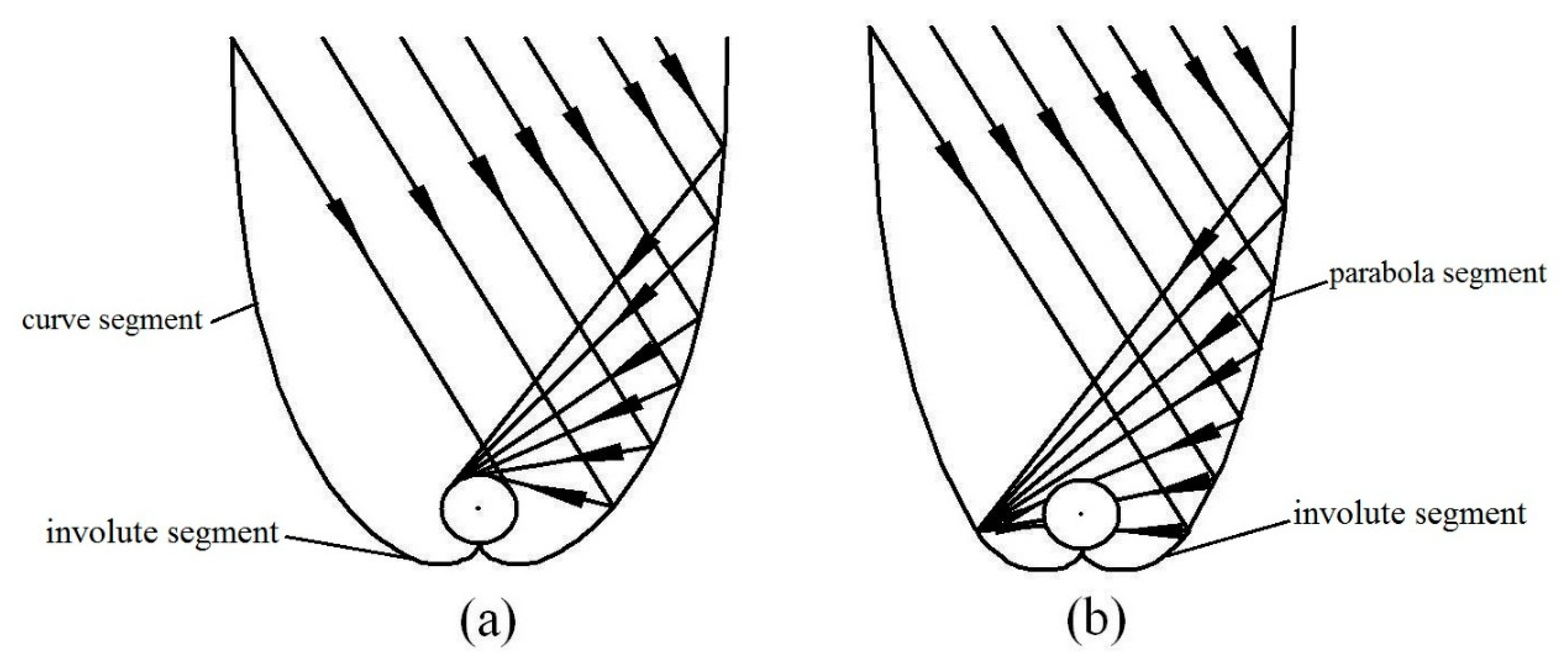
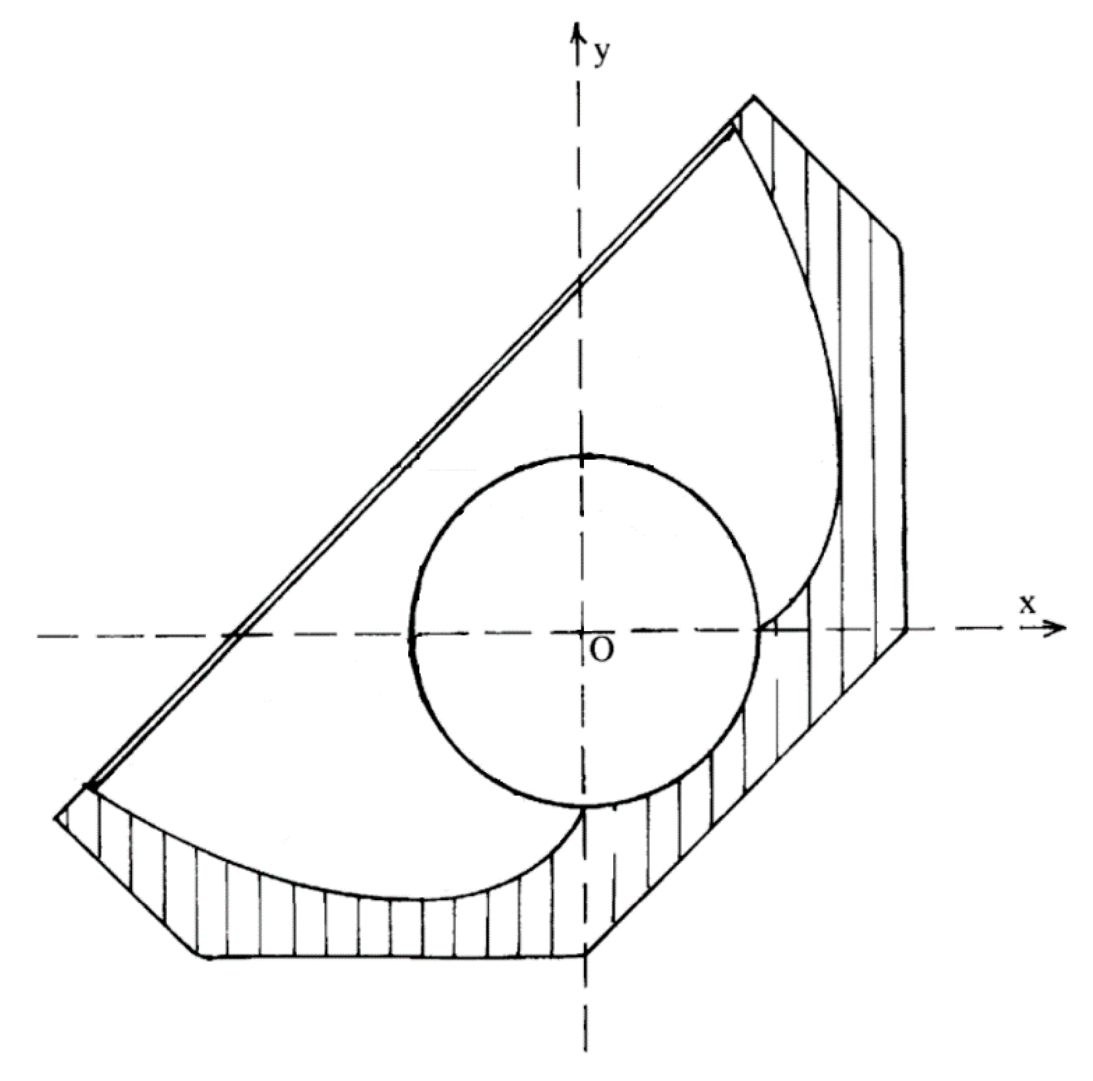
The two-dimensional curve of the tubular absorber CPC includes an involute segment and curved segment. There are mainly two types of curves for the tubular absorber CPC (Figure 1), in which the involute segment is similar and the curved segment is different. Winston [4] and Ortabasi et al. [8] proposed the first type of curve and derived its curve formula (Figure 1a). Another type uses a flat CPC curve by replacing the flat receiver with a tubular absorber and an involute segment. The other side of the curve is a part of the parabola (Figure 1b). This paper analyzes the CPC based on the first type of curve, which is called the “ideal concentrator.” It is superior to the second type of curve in terms of height, concentration ratio, and average number of reflections.
A CPC reflects all light within the maximum half acceptance angle θmax to the receiver, where θmax is defined as the maximum angle between the incident light, which can reach the receiver, and the axis of symmetry of the CPC. Each CPC has a theoretical maximum concentration ratio, which can be calculated from θmax (here, 2-D geometry) [4]:
The profile curve of a tubular absorber CPC contains an involute segment and a curve segment. The coordinates of the CPC curve are given by Equations (2) and (3) [8].
For involute segments, I(t) is given by Equation (4):
For curve segments, I(t) is given by Equation (5):
where r is the radius of the tubular absorber, t is angle variable parameter, and θa is acceptance half angle.
2.2. Gap Design of Tubular Absorber CPC
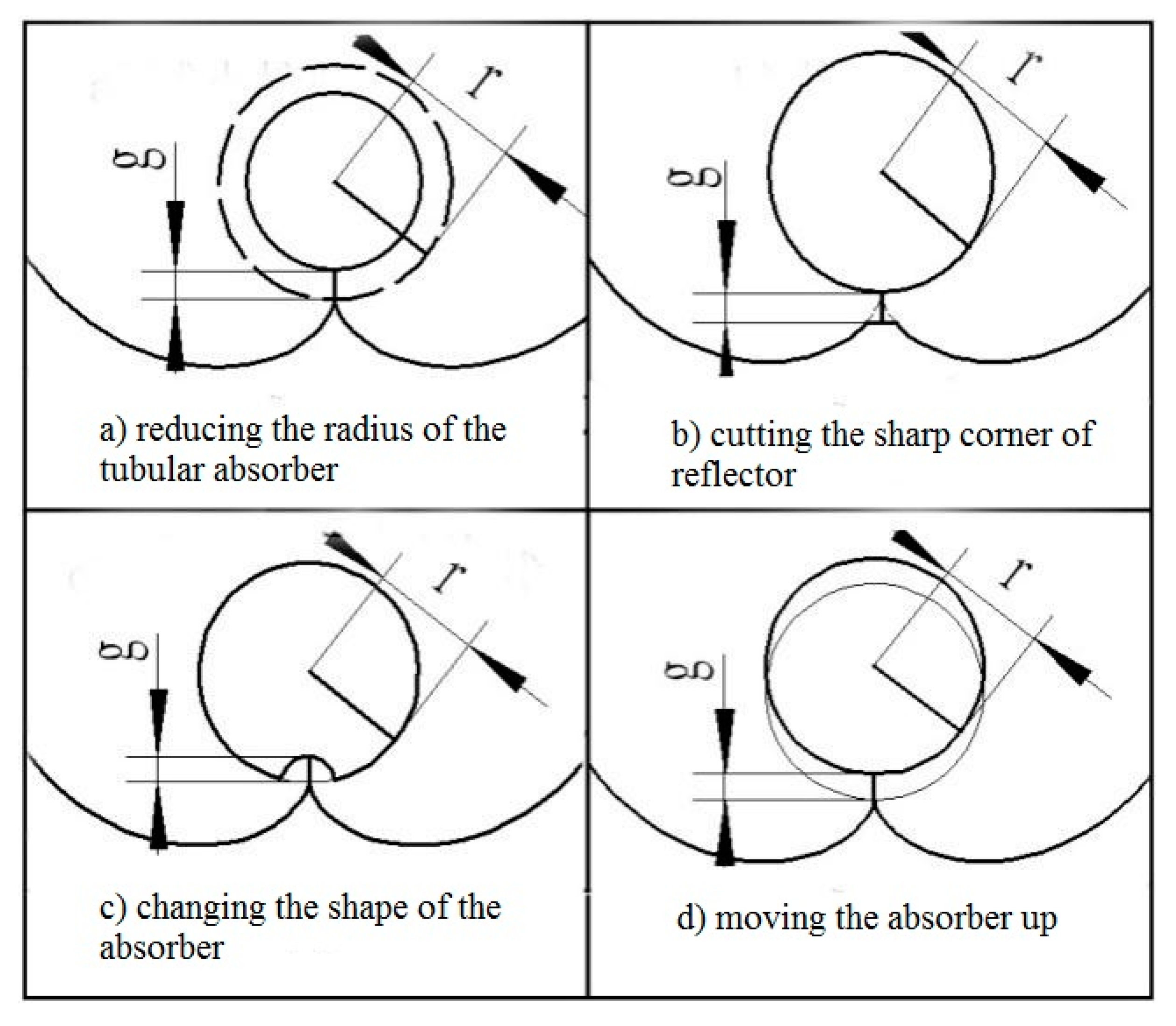
In practical applications, the CPC absorber and the reflector cannot be in contact as physical contact could cause heat losses through heat conduction and the thermal stress could deform the reflector. In addition, for an external concentrating tubular absorber CPC, contact is not possible, due to the vacuum collector tube used [18]. Therefore, a gap between the bottom of the absorber and the reflector for the tubular absorber CPC is required, which will, however, reduce the concentration ratio and cause some loss of solar radiation. Previous studies have shown that the gap loss of solar energy varies from 5% to 20% [10,11,12,14]. Rabl [12] proposed three ways to create gaps: (a) Reducing the radius of the tubular absorber; (b) cutting the sharp corner of the reflector; (c) changing the shape of the absorber (Figure 2). In practice, the method of moving the absorber up is mostly employed (Figure 2d). Mcintire proposed a W-shaped curve instead of the sharp corner of the reflector to avoid gap loss, but this reduced the concentration ratio by 15% [10,11]. Ortabasi [8] proposed another method to form a gap in the CPC by changing the starting point of the involute.
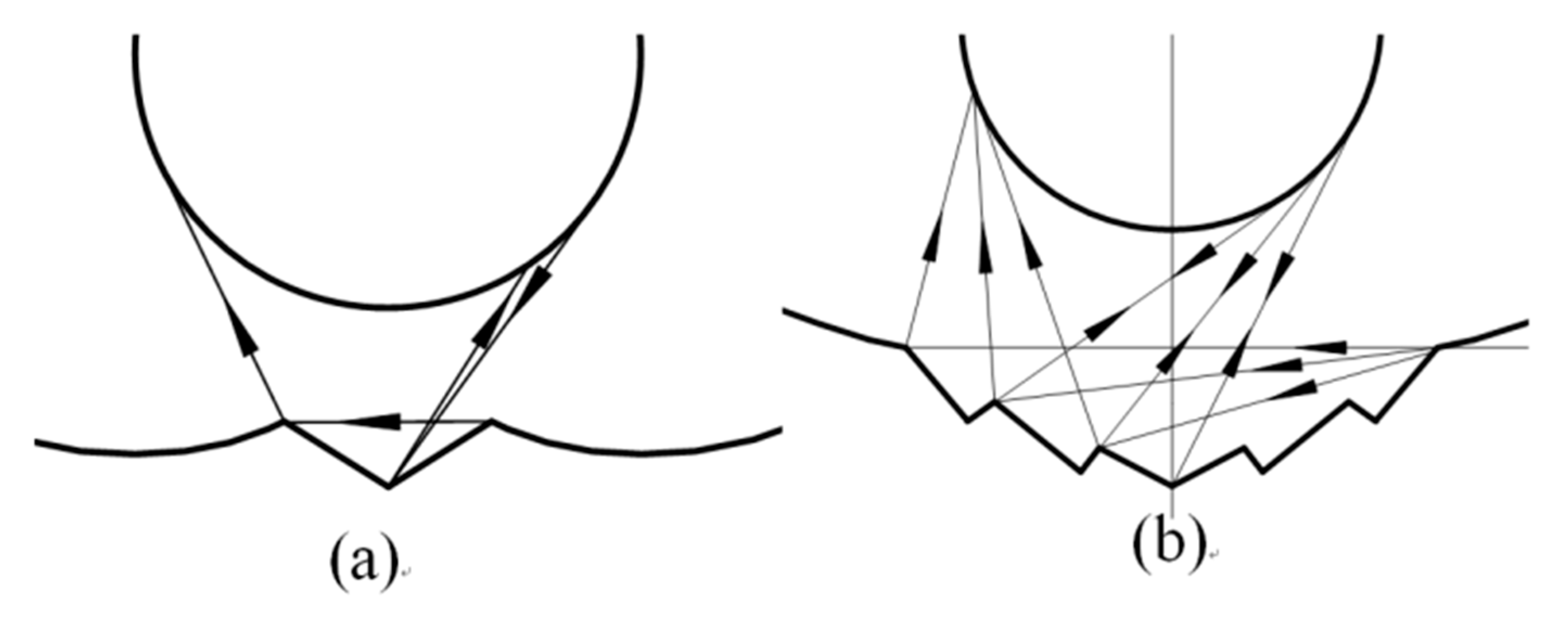
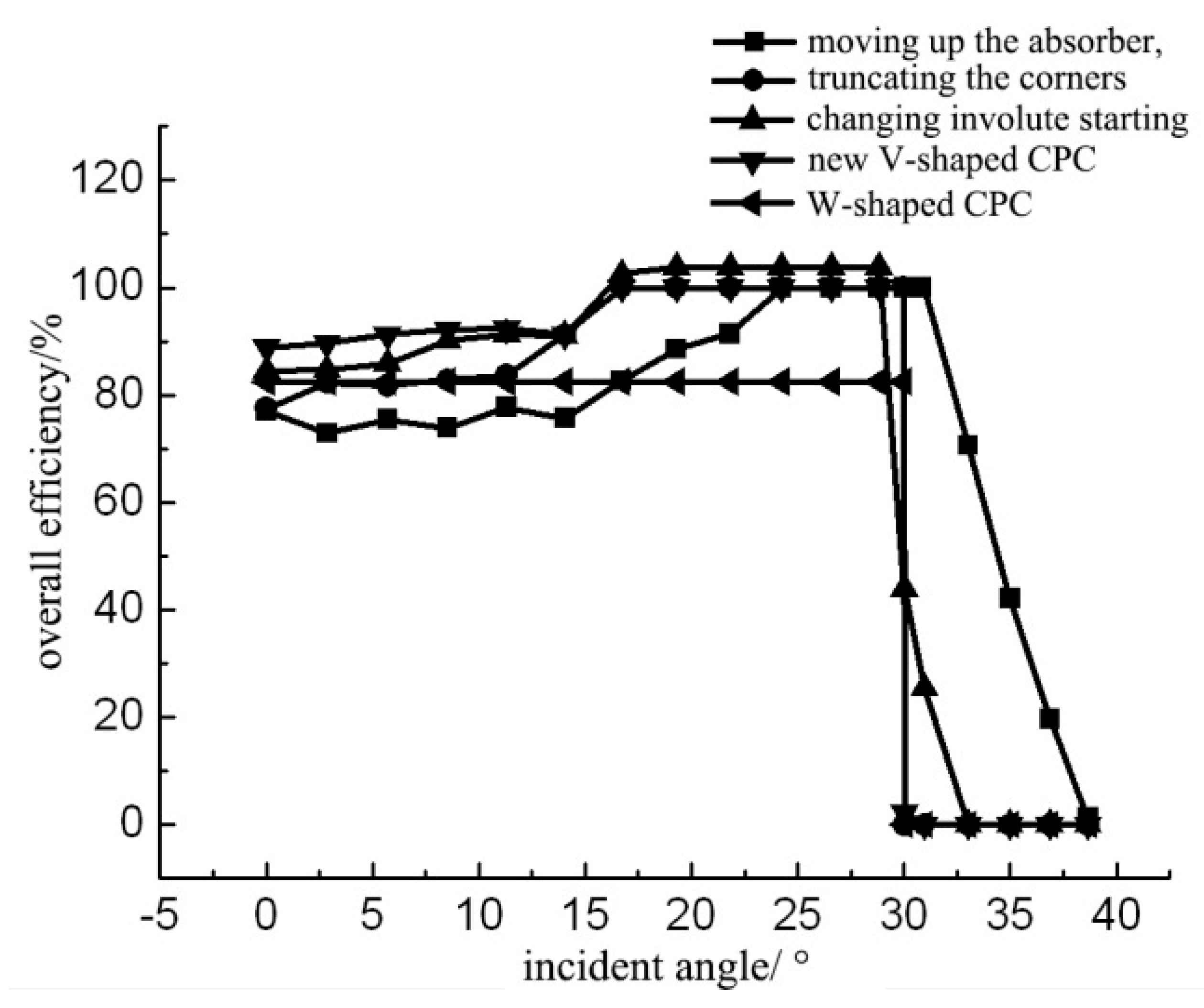
Wang et al. [27] proposed a tubular absorber CPC with a V-shaped profile at the bottom of the reflector based on the edge-ray principle (Figure 3 and Figure 4). They also studied its key parameters such as geometrical optical efficiency, reflectance, and transmittance and absorption ratio, based on geometrical optics and ray tracing. They showed how to create a gap in the CPC based on the size of the designed CPC gap, and proved that a CPC with a V-shaped profile has a high optical efficiency and good application prospects. The overall efficiency is defined as the product of the relative concentration ratio and the gap efficiency. As the overall efficiency is a relative value, some methods may have an efficiency greater than unity under the condition of reducing the acceptance range.
2.3. Truncation of Tubular Absorber CPC
The complete CPC, especially with a small acceptance angle, has a larger height-to-width ratio and needs more material for the reflector than the general collectors. The reflectors at both ends of the CPC have little effect on the concentration of solar radiation. Therefore, the height of the CPC and the material of the reflector can be reduced by truncating the CPC.
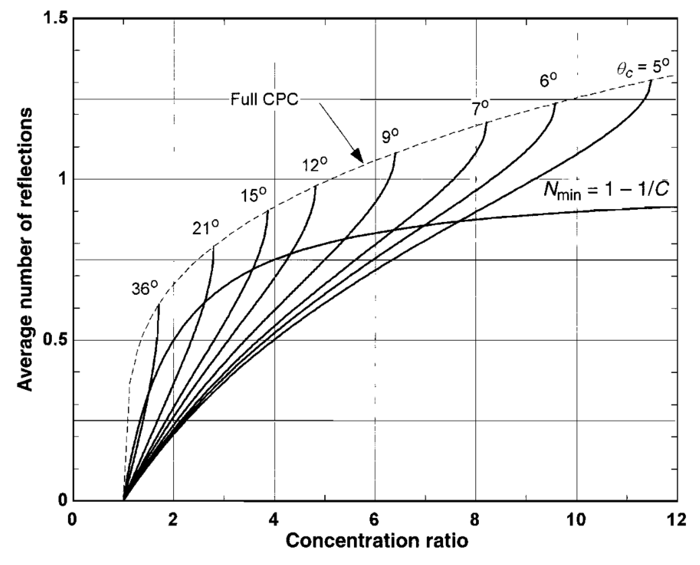
Some researchers have studied the truncation of CPCs [4,5,8], and presented a relationship between the truncation ratio and length to aperture ratios with different acceptance angles. Winston [4] studied the truncation of CPCs based on the average number of reflections. The recommended truncation ratio can be selected based on the Nmin curve in Figure 5, where C is the geometric concentration ratio and Nmin is the reference average number of reflections.
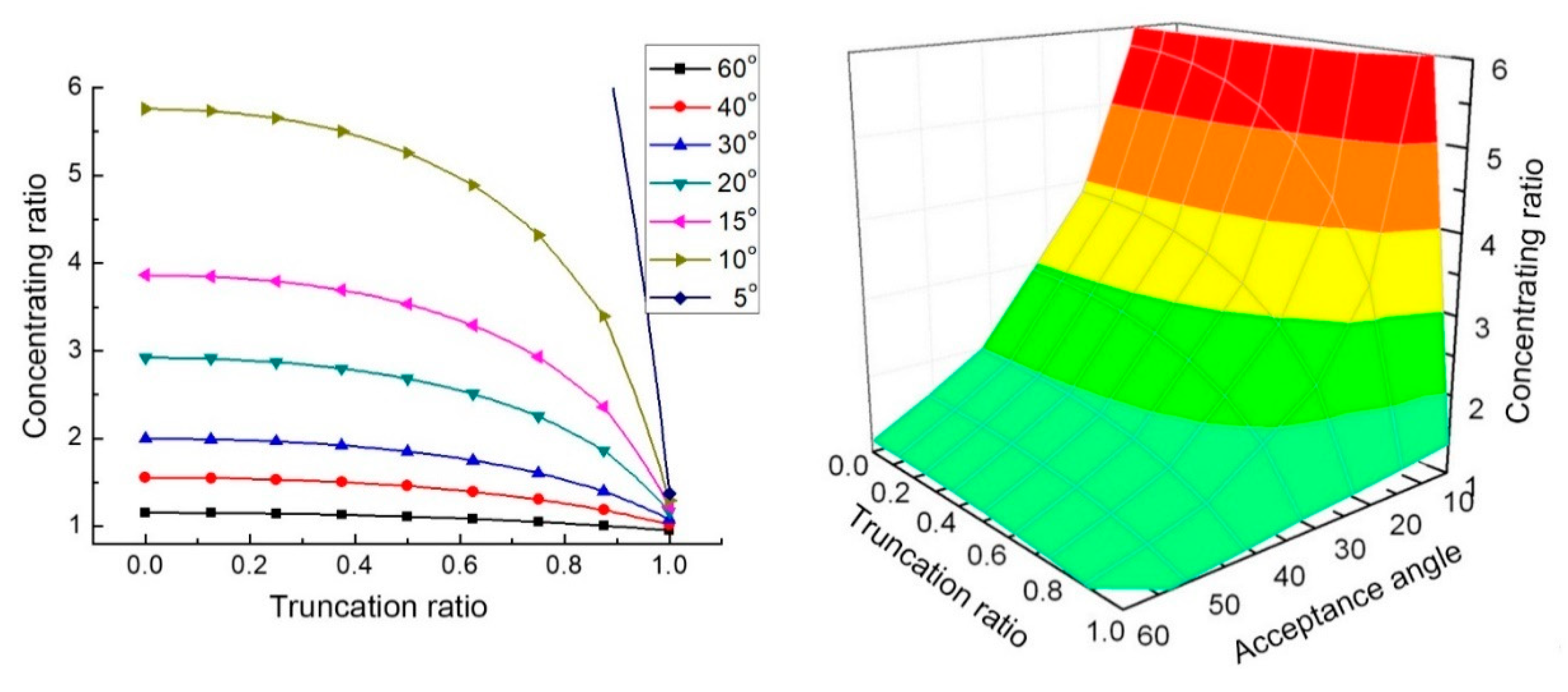
Yu et al. presented the relationship between the concentrating ratio, the acceptance angle, and the truncation ratio [27,30] (Figure 7). It can be seen from the figure that the larger the truncation ratio, the greater influence of the truncation on the concentration ratio. When the CPC truncation ratio is 0.4, the loss of concentration ratio is less than 5% [30].
2.4. Deformation of Tubular Absorber CPC
Errors may occur when the CPC is manufactured and installed, which can affect the concentrating effect of the CPC. Rabl [12] showed that for a tubular absorber CPC with radius r, when the displacement deviation of the receiver or reflector is g, the optical loss is as follows.
L = 1 − 2/π·arccos(g/2r) ≈ g/3r.
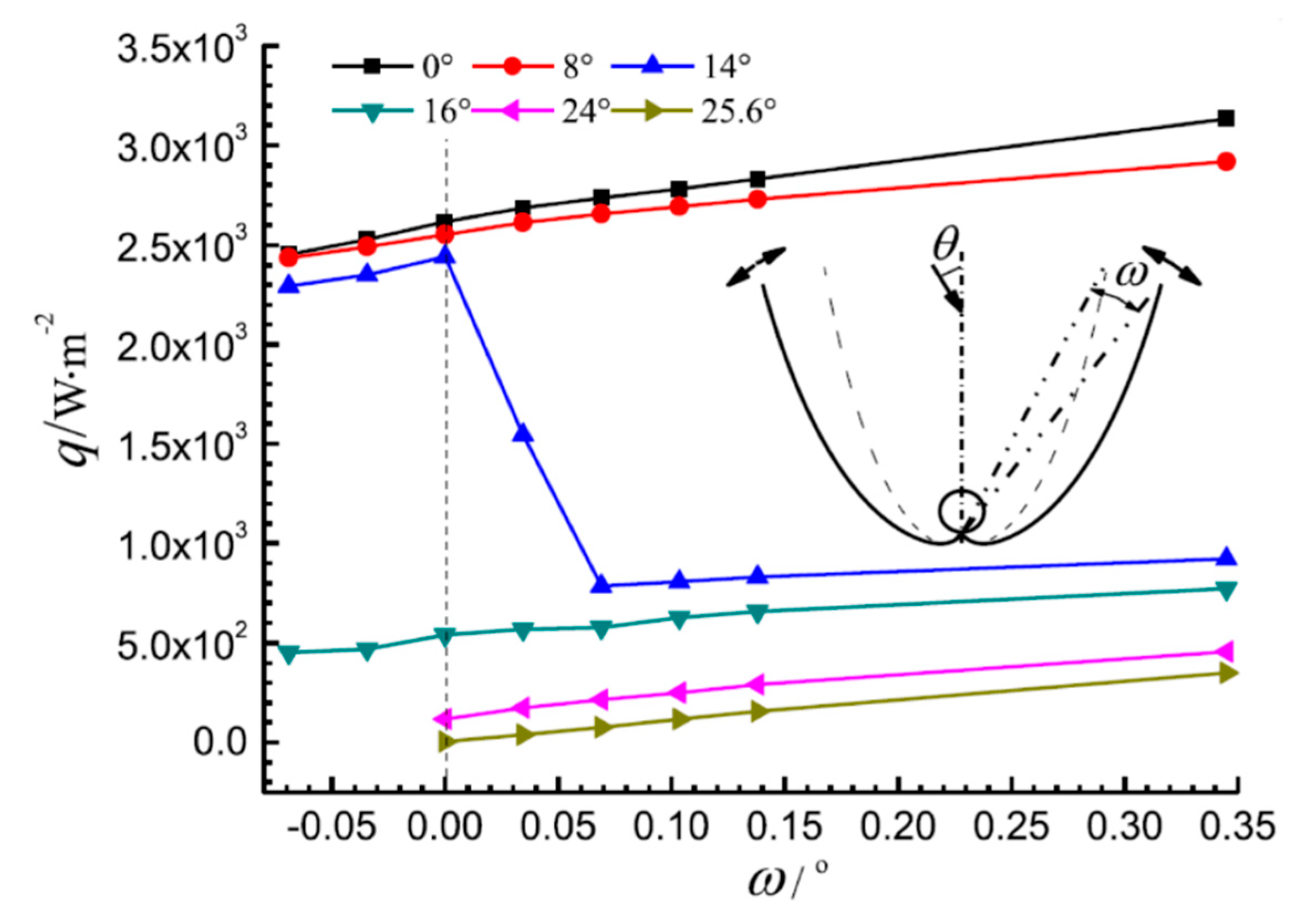
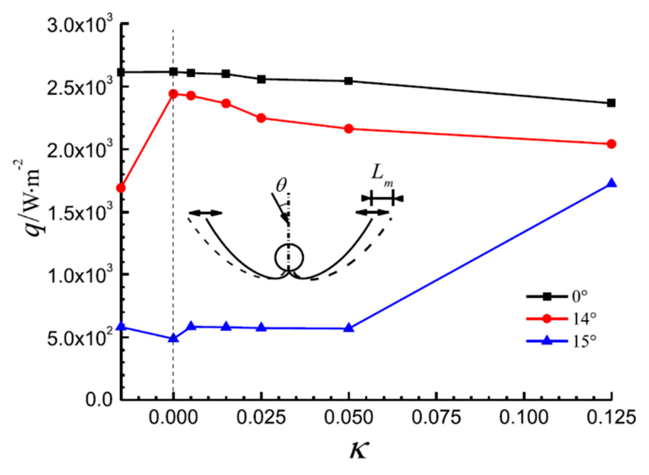
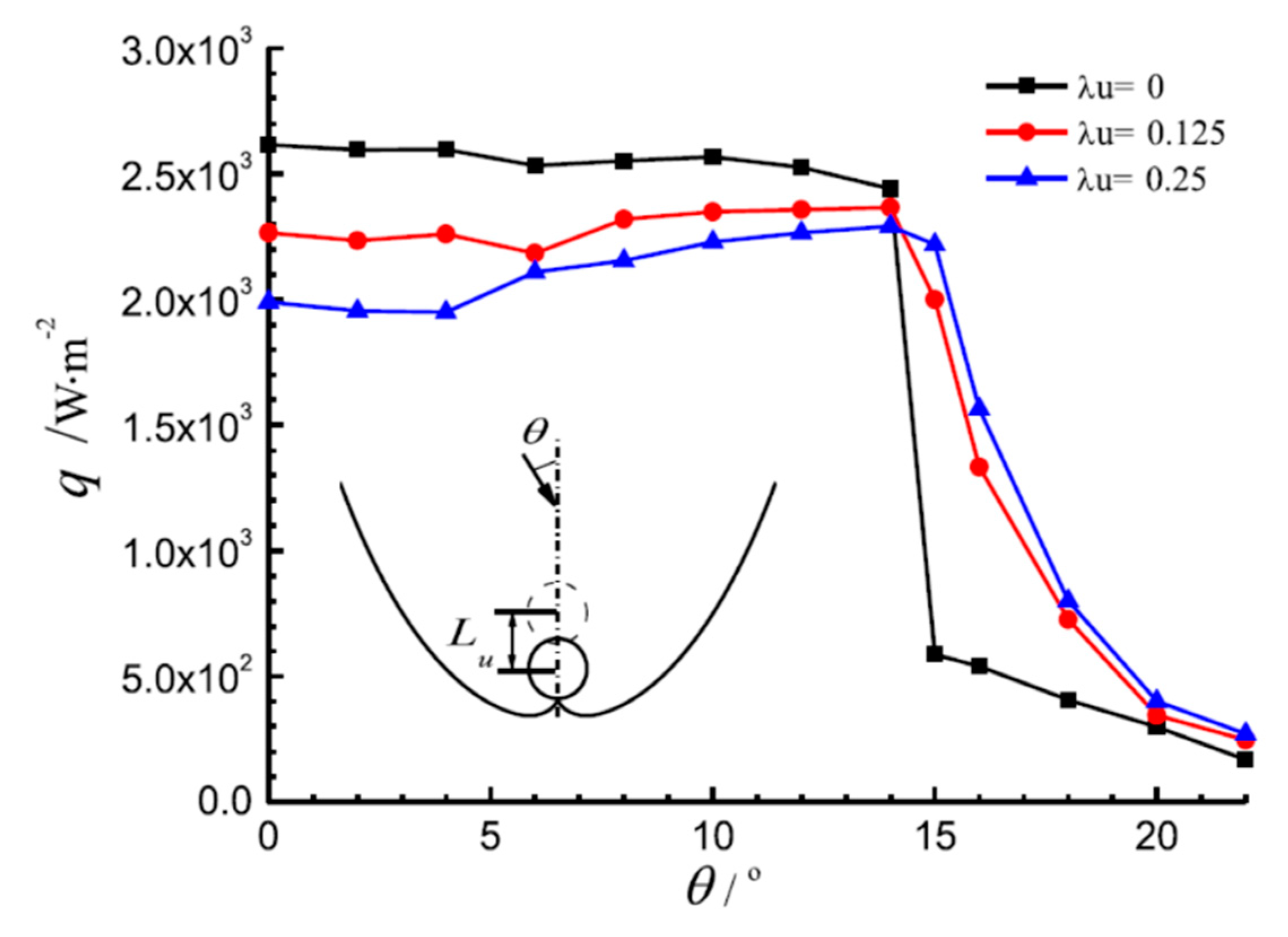
Xu et al. [31] studied the deformation of a tubular absorber CPC by the Monte Carlo ray-tracing method, and analyzed the effects of the deformation factor such as the rotation of the reflector, translation of the reflector, and position offset of the absorber. Their research showed that when the rotation and translation deviation of the reflector reached a critical value, the optical loss significantly increased, and the effect of downward, rightward, and leftward offsets of the absorber was greater than that of the upward offsets (Figure 8, Figure 9 and Figure 10, C is the concentration ratio, Ct is the CPC truncation ratio, ω is the rotation angle of the reflector, κ is a dimensionless parameter of reflector translation, λu is a dimensionless number of absorber position offset, and θ is the angle of incident light).
2.5. Summary
Based on the above analysis, the following conclusions can be made:
- (1)
- For the formula curve of the tubular absorber CPC, it is recommended to choose the curve formula in Figure 1a, and Equations (2)–(5).
- (2)
- The CPC gap should be designed according to the size of the gap given in Table 2.
- (3)
- For the truncation of a tubular absorber CPC, ratios in Table 3 are recommended.
- (4)
- The design, processing, and installation errors of the CPC should be limited to a range defined by Monte Carlo ray-tracing calculations, which can significantly reduce the impact of these errors on the CPC performance.
3. External/Internal Concentrating Tubular Absorber CPC
The tubular absorber CPC is usually composed of a CPC reflector and an evacuated tubular absorber, which is put inside a glass tube. According to the position of the reflector and the glass tube, the CPC can be divided into external concentrating CPC and internal concentrating CPC.
3.1. External Concentrating Tubular Absorber CPC
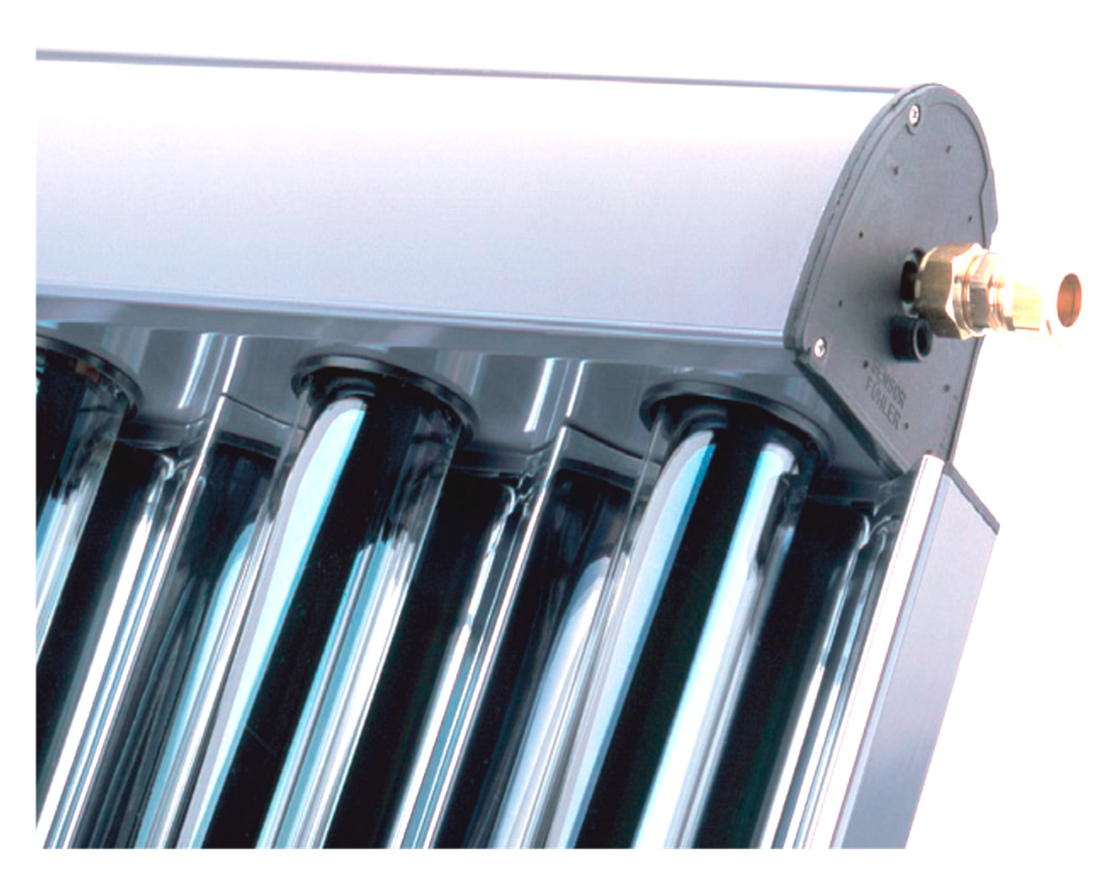
External concentrated solar collectors are the most common collectors, which are simple in construction and are not limited by the glass tubes but are generally truncated (Figure 11).
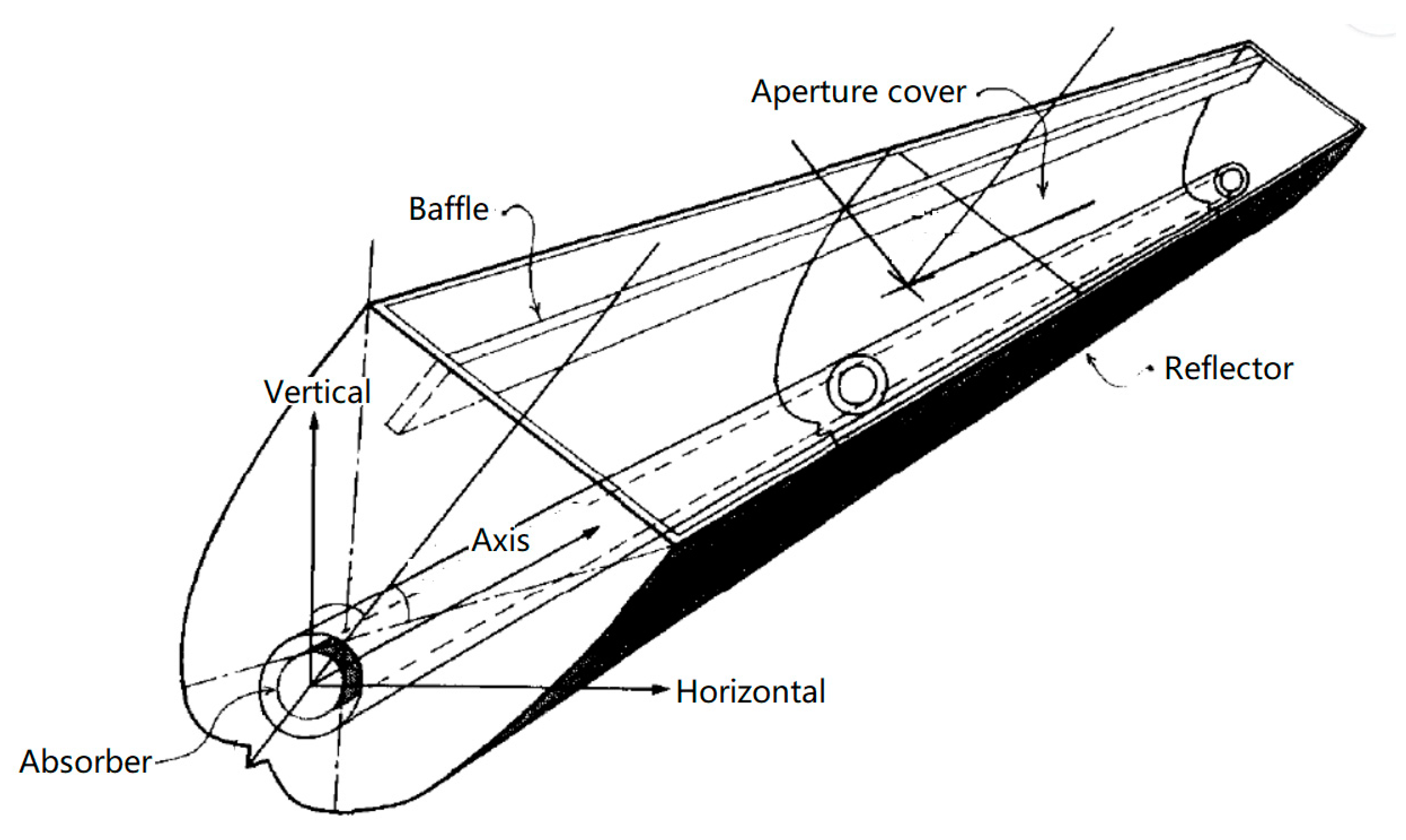
A theoretical and experimental investigation on modifications of the optical and thermal performance of external concentrating tubular absorber CPCs was performed by Eames (Figure 12). Their research showed that by setting a baffle inside the CPC, internal convection can be reduced, thereby reducing heat loss [32].
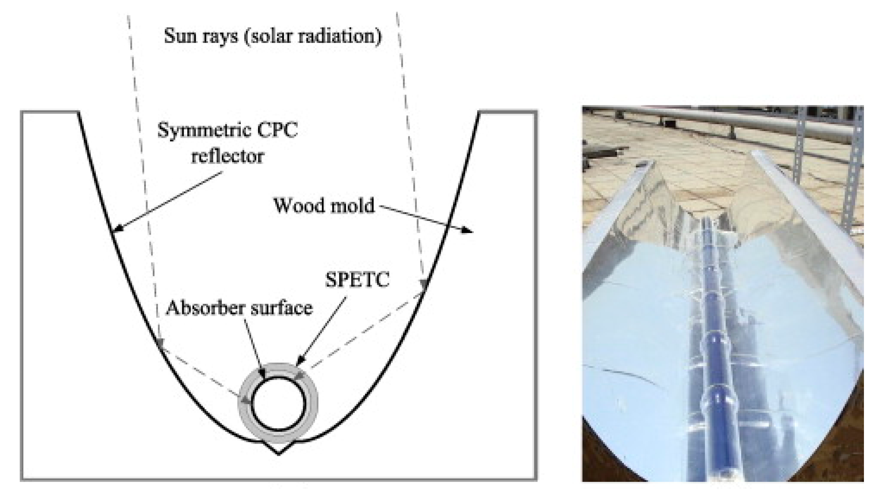
Li et al. [33] improved the external concentrating tubular absorber CPC and developed a cost-effective single-pass evacuated tubular collector (SPETC). Experimental studies and theoretical analyses were carried out to show that this collector can be used for heating and cooling systems in industrial processes (Figure 13).
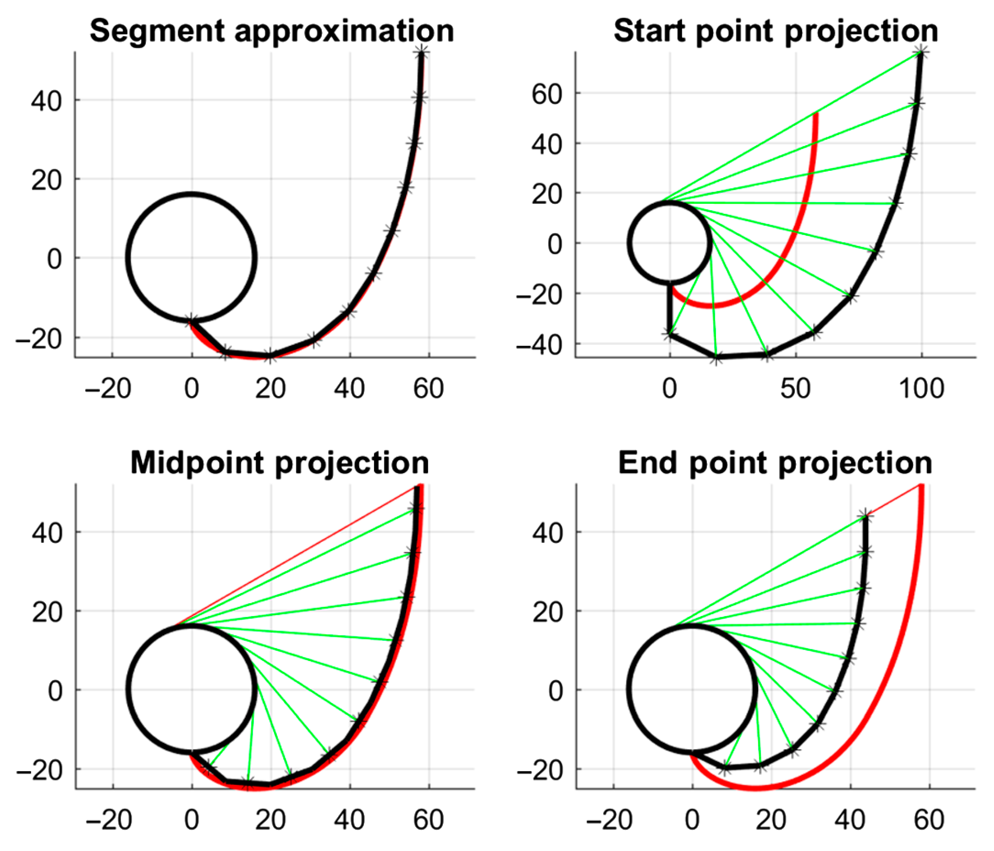
Considering the difficulty in manufacturing an ideal CPC reflector profile, Widyolar et al. [34] proposed an approximate method to generate CPC-like profiles by using a series of small flat segments (Figure 14). A flux efficiency (FE), which relates the optical efficiency and geometric concentration ratios, was also introduced for comparison between ideal and nonideal concentrators. The results show that the general rule of thumb to achieve a high FE is to keep segments lengths less than 5% of the receiver circumference. FE is actually an alternative way of designing a CPC under real-world constraints.
3.2. Internal Concentrating Tubular Absorber CPC
Ortabasi and Buehl [8] proposed the internal concentrating tubular absorber CPC (internal cusp reflector with heat pipe) in 1997. The curve formula and optical properties were analyzed in detail. They also studied the optical route and analyzed the influence of positional deviation on the concentrating performance by using the Monte Carlo ray-tracing method.
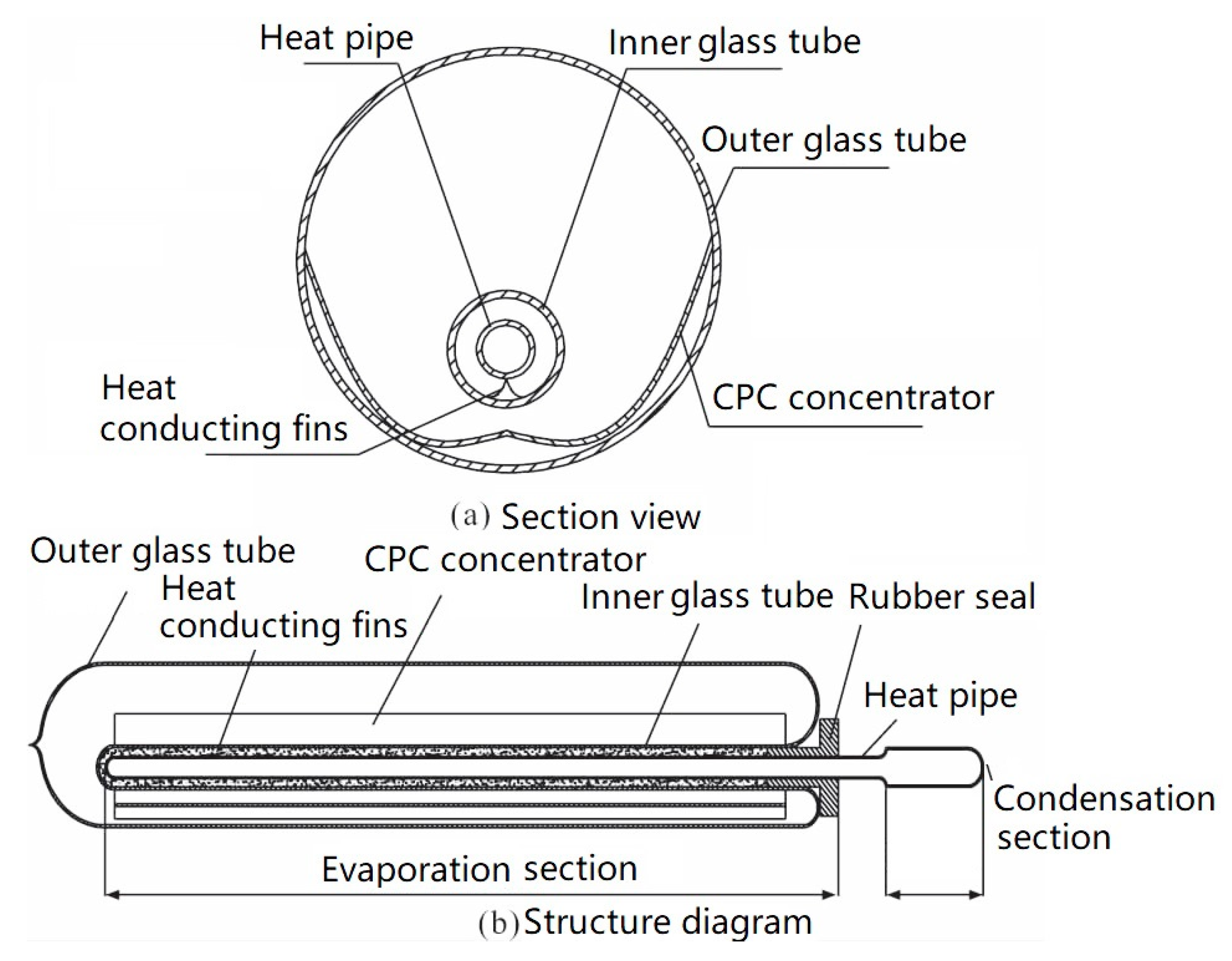
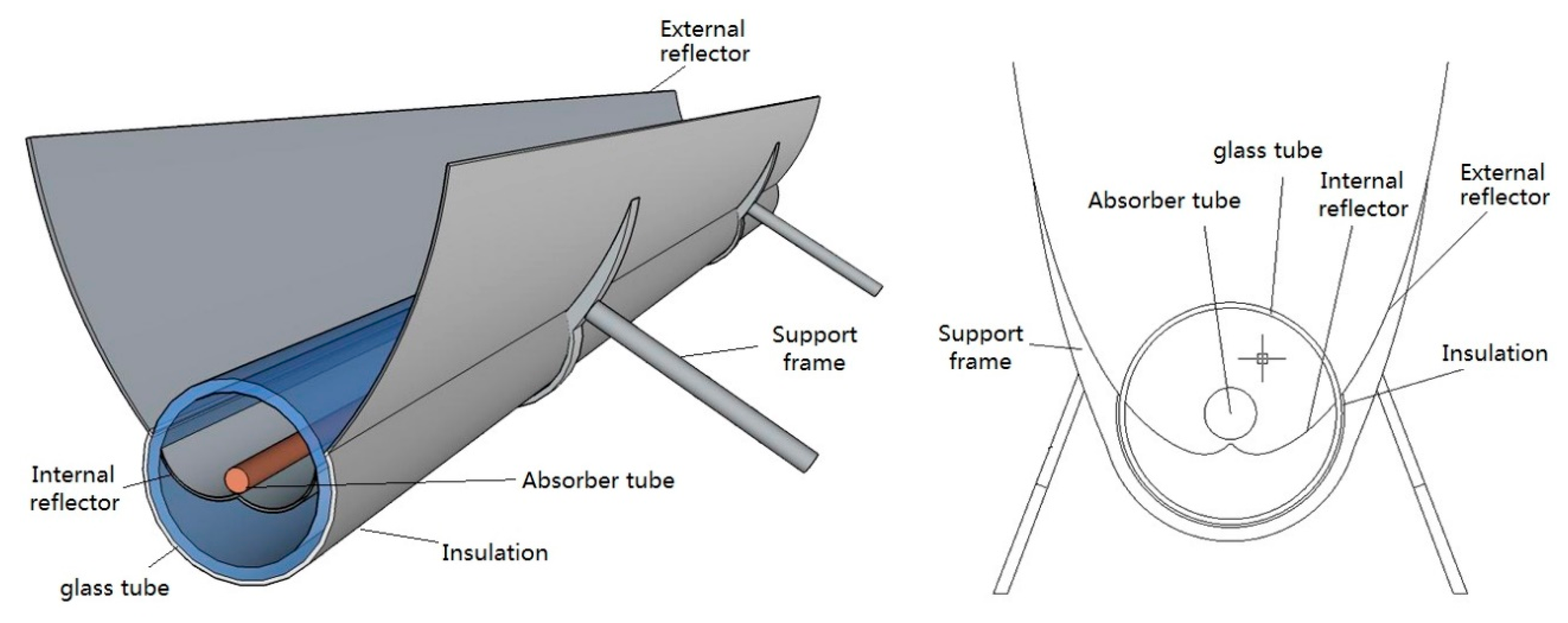
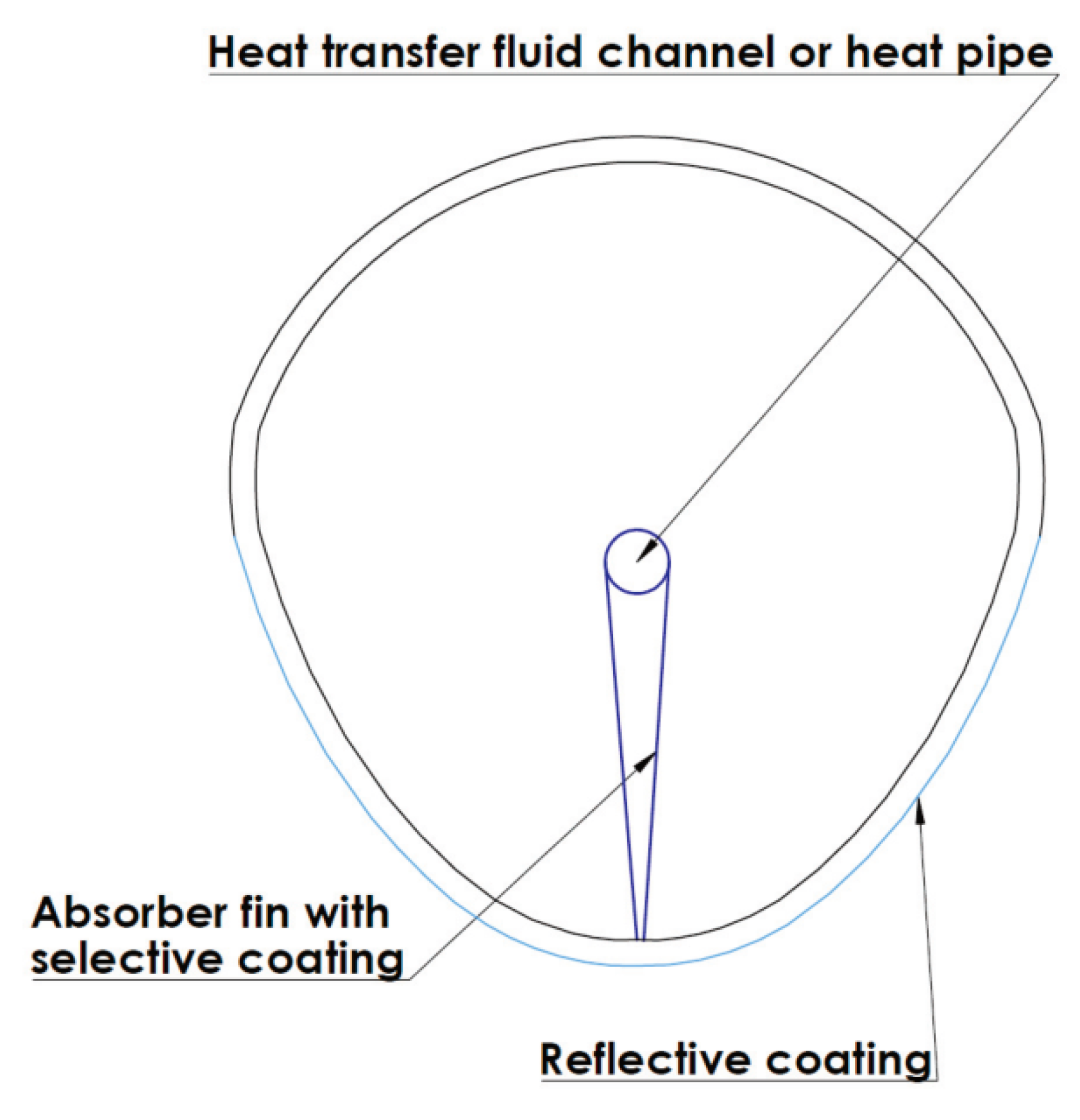
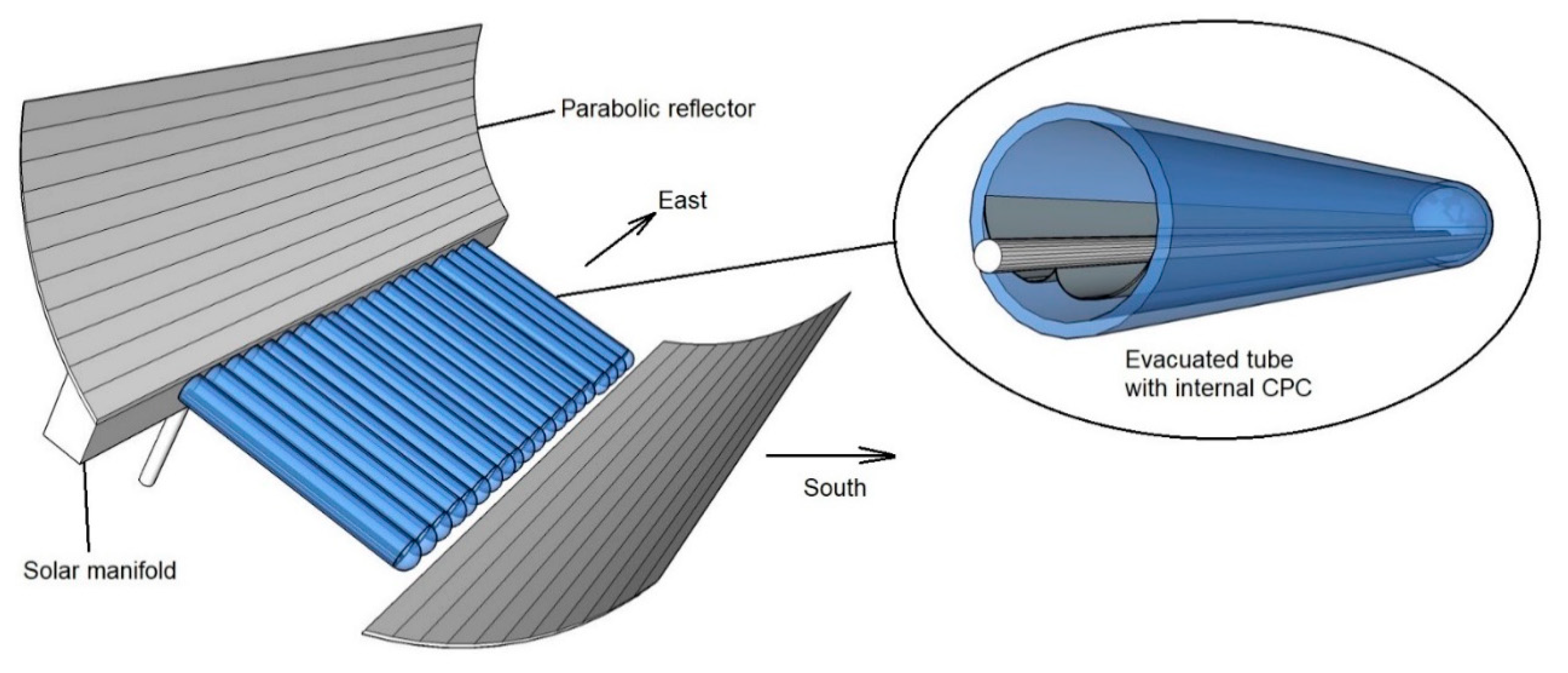
Several innovative designs for the internal concentrating tubular absorber CPC have been proposed by [30,35,36]. Yuan et al. [37] presented the temperature performance of an internal concentrating CPC with a heat pipe. The schematic of the CPC is shown in Figure 15.
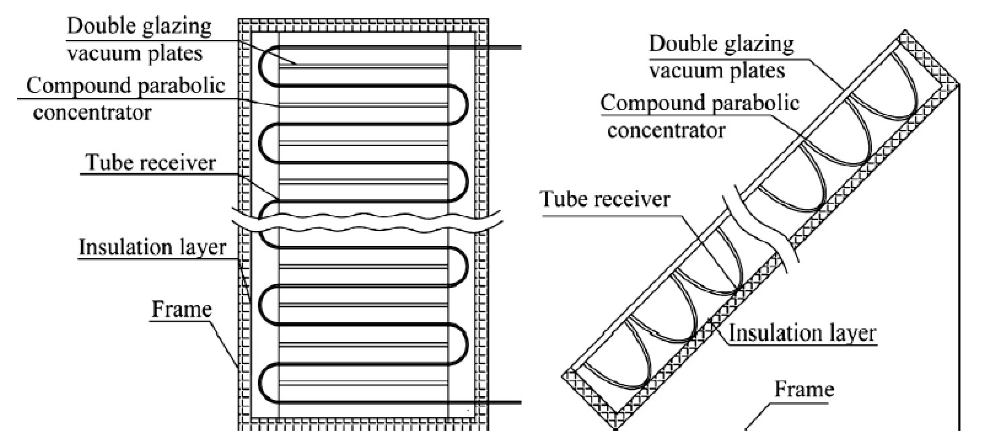
Shown in Figure 16, a new type of collector with the new V-shaped CPC, heat pipe, and inner reflector is designed. The designed configuration, designed parameters, and adoptive technics are presented. A series of detailed models were built, such as an optical efficiency model, acceptable solar radiation model, and thermal performance model [30].
3.3. Internal and External Concentrating Combined CPC
A tubular absorber CPC combination of an internal concentrate and external concentrate was proposed by Yu et al. [38] (Figure 17). The gap loss could be reduced compared to the external concentrating CPC, and the aperture size of the CPC was not limited by the glass tube compared to the internal concentrating CPC. It could increase the concentration ratio, reduce heat losses, and raise the temperature of the working fluid.
3.4. Summary
Based on the above analysis, the characteristics of three types of concentrating options for the tubular absorber CPC are compared as follows (Table 4).
4. Structure of Tubular Absorber CPC
4.1. Absorber of Tubular Absorber CPC
4.1.1. CPC with Heat Pipe
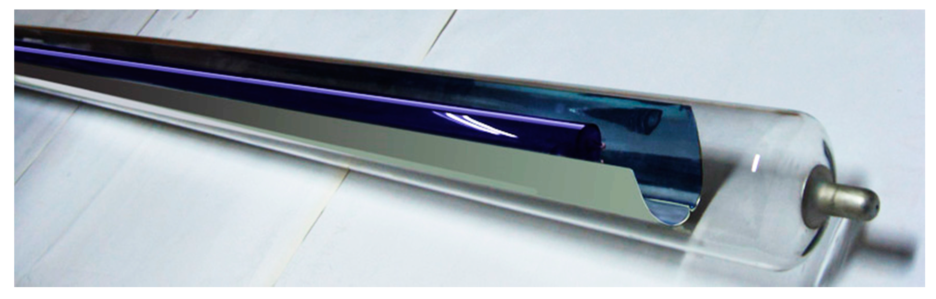
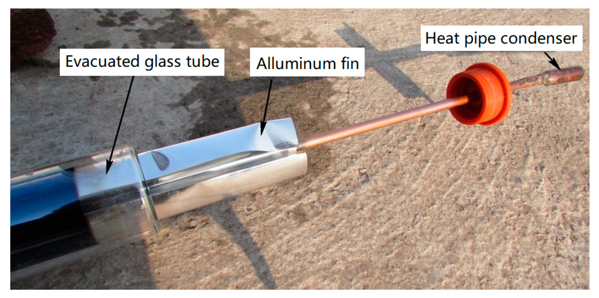
A CPC with an evacuated tube heat pipe is presented in Figure 18. It consists of an aluminum fin reflector and a heat pipe evacuated tube. The collector has the advantages of both the heat pipe and the CPC, i.e., fast response and higher temperature [39]. A CPC with a closed-end pulsating heat pipe (PHP) has also been reported, which could achieve more stable performance on rainy days [40].
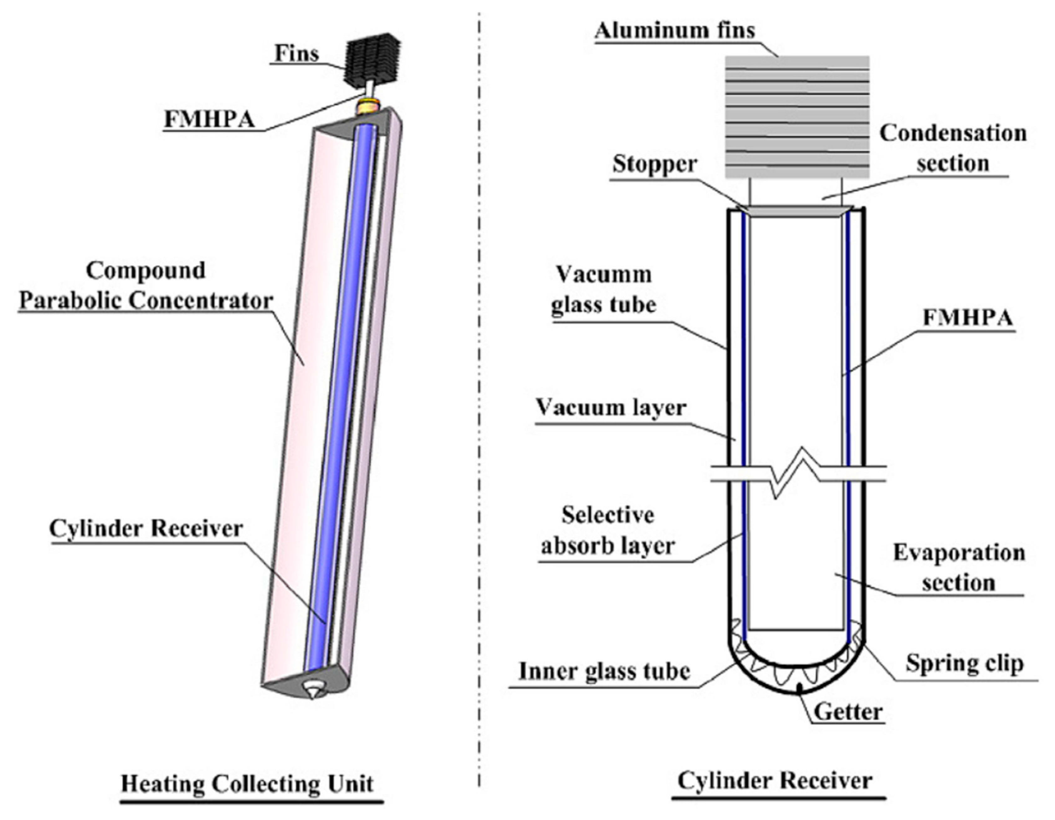
Zhu et al. [41] proposed a solar air collector that uses flat micro-heat pipe arrays (FMHPA) as the absorber of the CPC (Figure 19). The heat pipe has a small thermal resistance in converting solar energy to heated air, thereby increasing the efficiency and operating temperature of a solar air collector.
4.1.2. CPC with U-Shaped Pipe
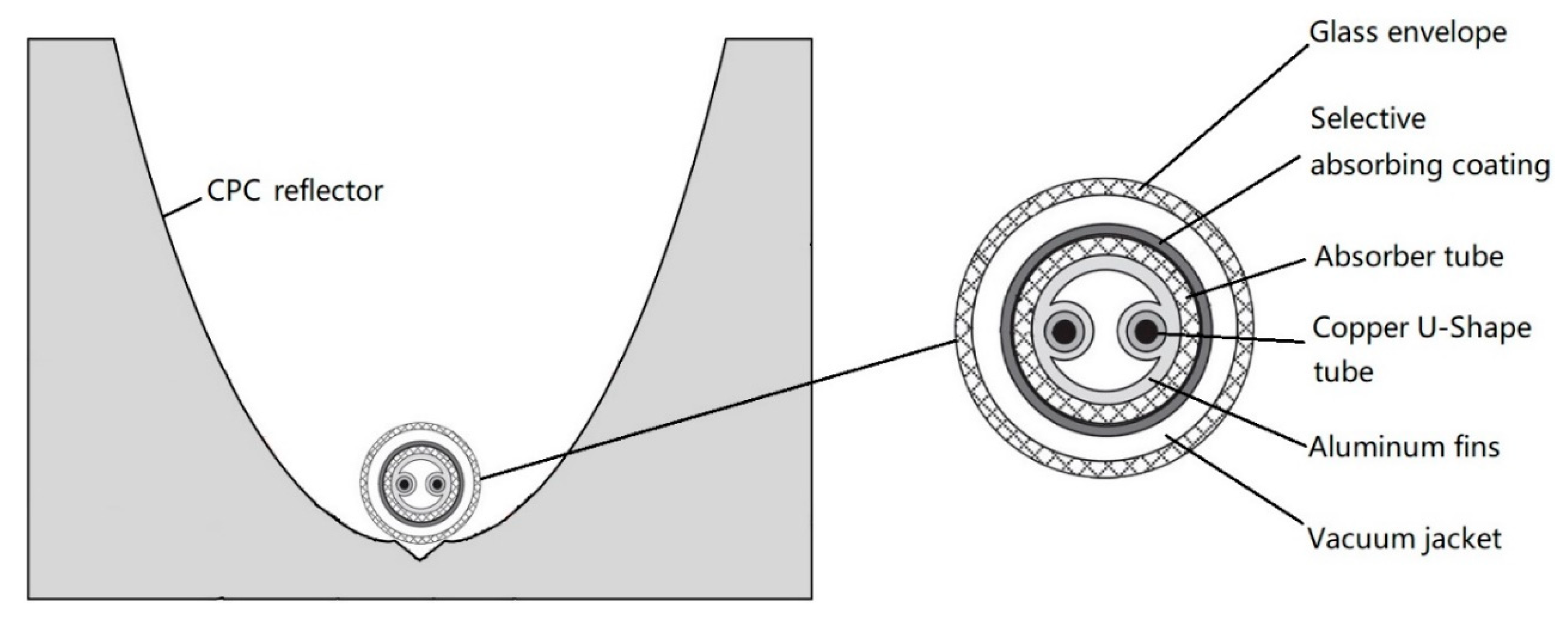
An evacuated solar collector with a CPC reflector and U-shaped pipe was proposed by [42,43,44,45,46,47,48,49]. An external concentrating CPC with a U-shaped pipe (Figure 20) was developed and tested, and test results of the 3× and 6× CPC with the U-shape evacuated tube were also reported. The results verified that these kinds of solar collectors are feasible for a wide range of intermediate-temperature solar applications (80 °C to 250 °C) [49].
4.1.3. CPC with Coaxial Pipe
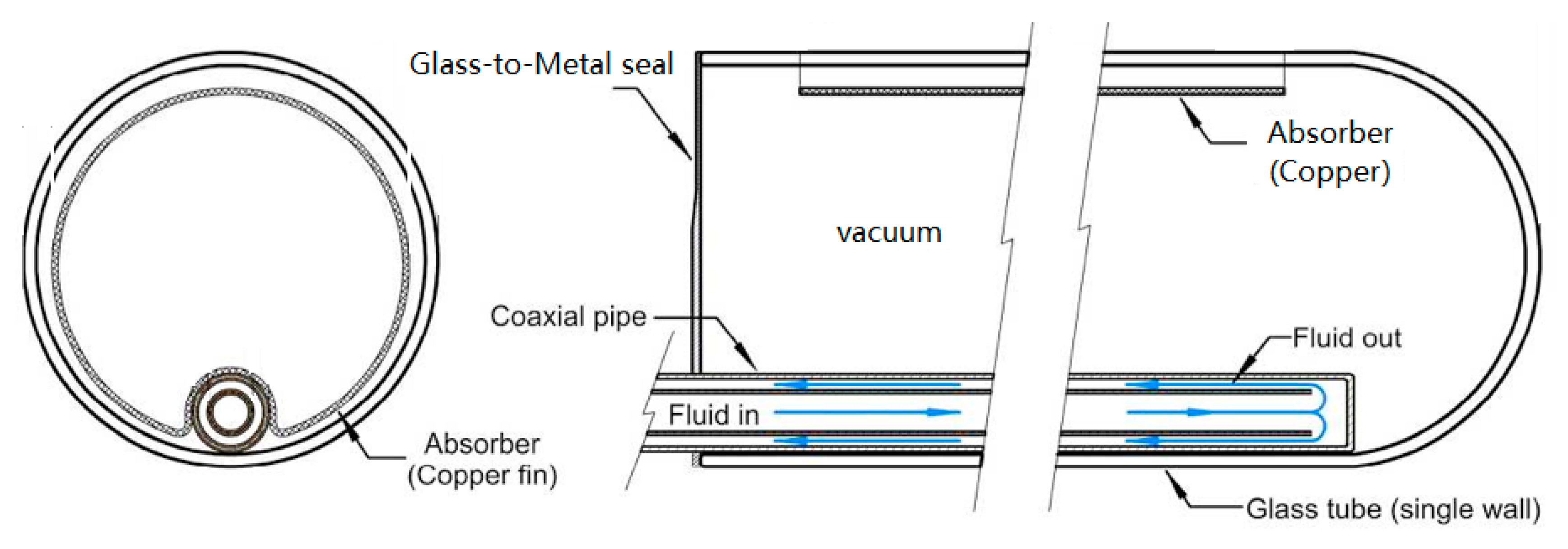
The receiver of the CPC contains a counter-flow tube that consists of a coaxial pipe attached to the absorber fin, which makes the directions of the working fluids opposite. This design minimizes the thermal stresses throughout the tubes and offers a more uniform heat transfer rate throughout the heat exchanger [50]. However, the flow resistance of the working fluid may increase.
4.1.4. CPC with Double Tubes
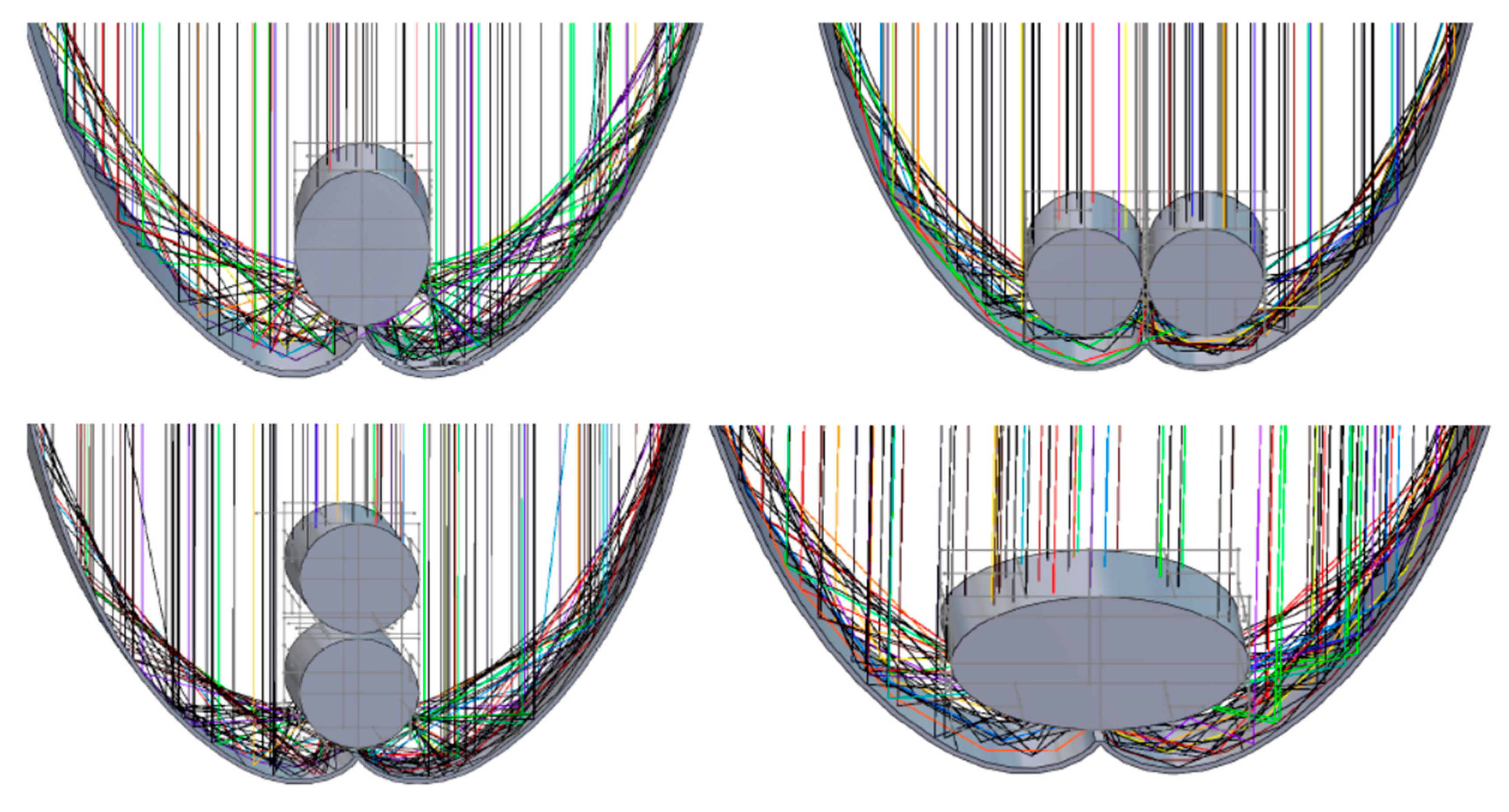
A CPC with double tubular absorbers has been proposed by Abdullahi et al. [52] (Figure 22). The results of a ray-tracing simulation showed that a CPC with two tubes arranged horizontally and an elliptically shaped tube has a higher daily average optical efficiency than that of a CPC with a single absorber, while a CPC with two tubes arranged vertically has no effect.
4.1.5. Other Forms of Absorbers
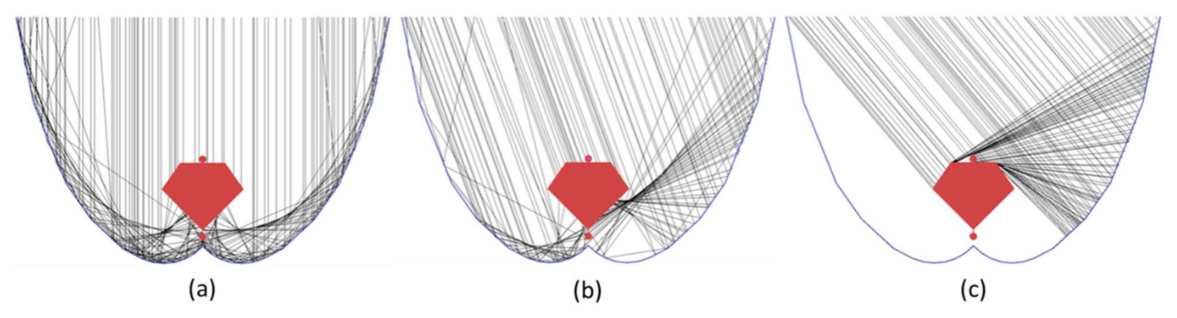
Two new types of absorbers are introduced in the next section, but not fully tubular. Due to constraints with assembling with an ultrasonic welding machine, Widyolar et al. presented a CPC with a polygonal-shaped absorber, and proved that with a modified absorber shape, gap loss, and truncated reflector, a geometric efficiency 93% of an ideal CPC could be reached [53,54,55] (Figure 23).
4.2. Tubular Absorber CPC Modules
4.2.1. Tracking Compound Parabolic Concentrating (TCPC) Collectors
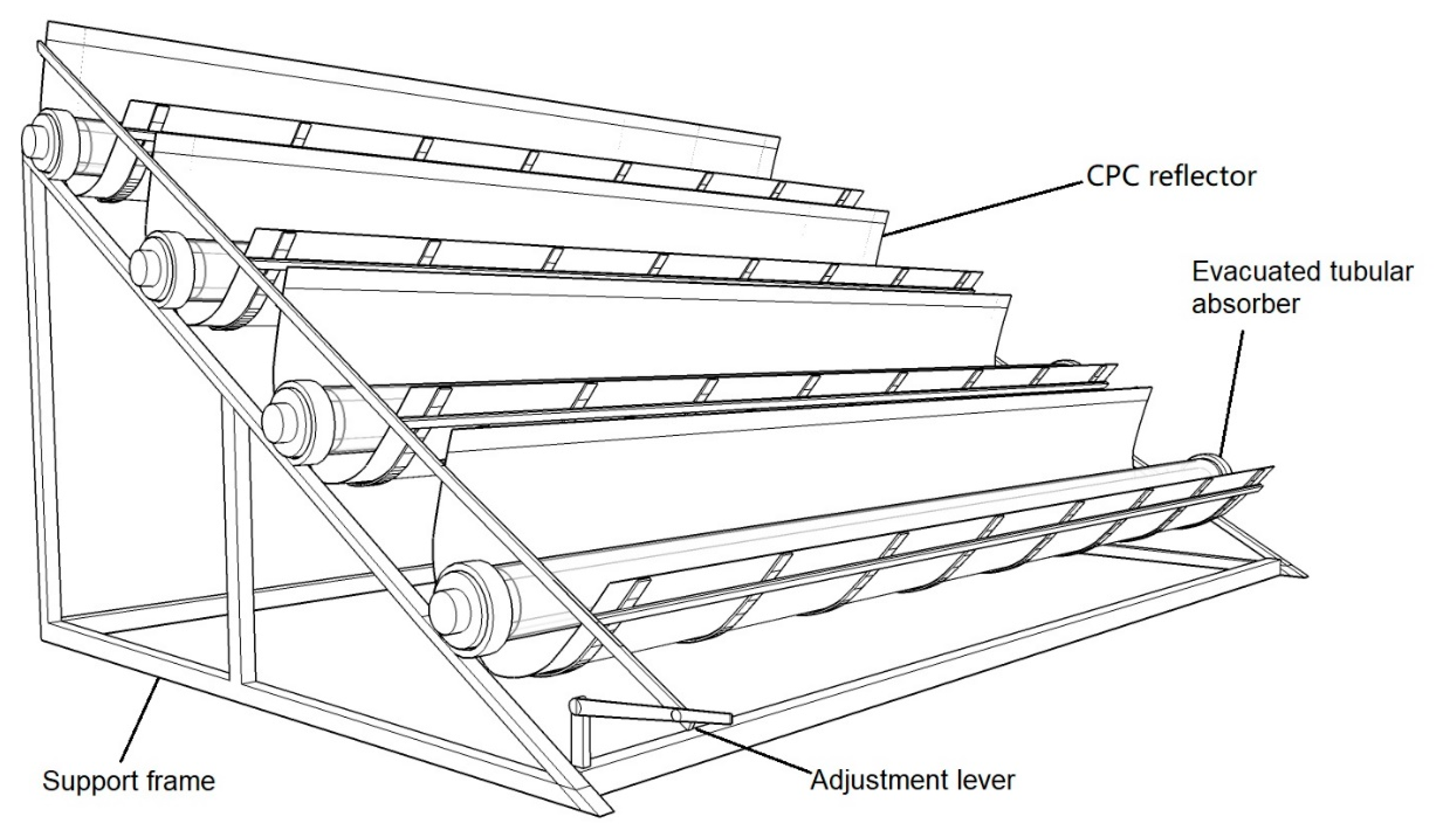
In the case a higher concentration ratio is required, the half-acceptance angle should be reduced. Thus, the orientation of the CPC solar collector needs to be adjusted several times during the day. A CPC that can adjust the angle according to the position of the sun is called tracking compound parabolic concentrating (TCPC). The east–west axis can adjust the angle seasonally through the adjustment lever (Figure 25).
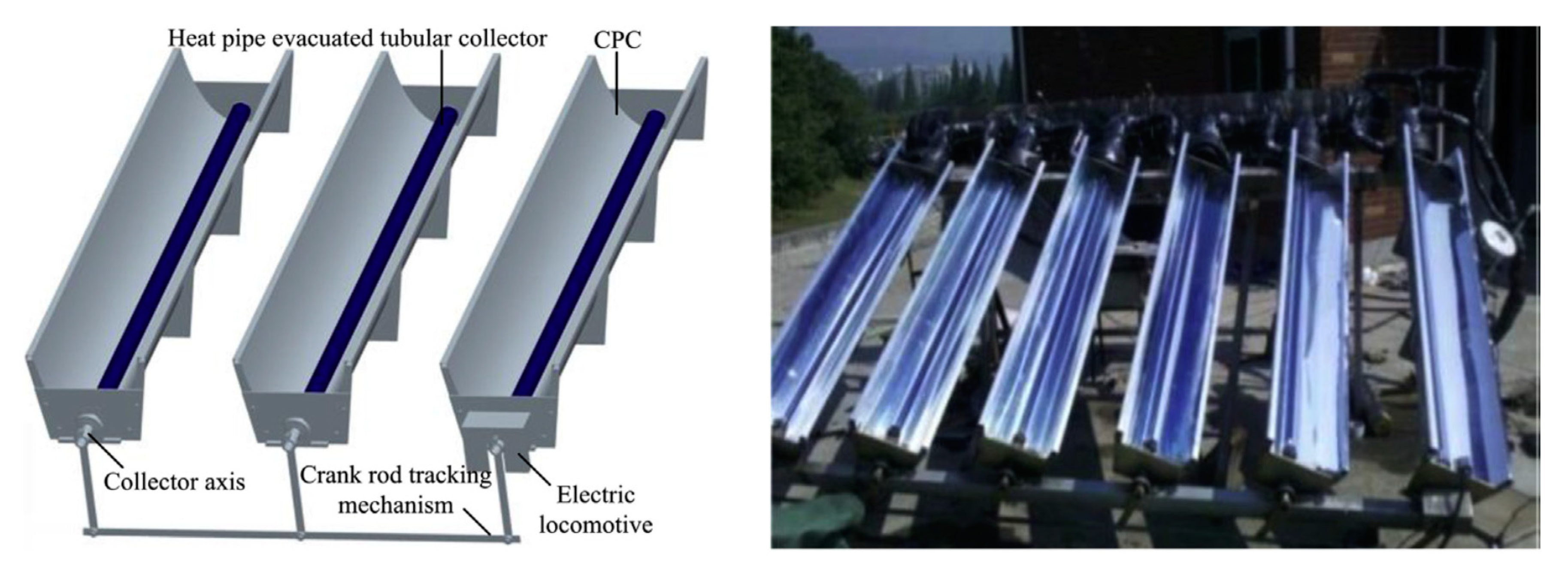
A north–south axis external concentrating TCPC with heat-pipe evacuated solar collector tubes, crank rod transmission mechanism, and electric device was presented by Wang et al. [57] (Figure 26). They proved that the intermittent tracking mode is more efficient than the continuous tracking mode for the CPC.
4.2.2. Two-Stage Concentrating CPC
Generally, a CPC can roughly be classified in two-dimensional (2D) and three-dimensional (3D) designs. The 2D CPC is called a linear CPC or trough-like CPC. A traditional 3D CPC is obtained by rotating a 2D meridian section of a CPC, whose absorber is a flat absorber, not a tubular one. Therefore, the quasi-3D CPC, which we discussed here, is a two-stage concentrating CPC, in which the first stage concentrates sunlight by a flat-type CPC and the second stage concentrates by an internal concentrating tubular absorber CPC (Figure 27). It can increase the concentration ratio and raise the temperature of the working medium [58].
4.2.3. Serpentine CPC
4.2.4. Integrated Collector Storage (ICS) with CPC
An integrated collector storage (ICS) solar water heater was designed by Souliotis et al. [61]. The absorber is a cylindrical tank that is mounted in a symmetrical CPC reflector trough shown in Figure 29. This design improves the solar thermal performance and reduces costs [61,62]. The ICS device was tested outdoors during a whole year and the experimental results showed that ICS systems have a similar performance to flat plate thermosiphon unit (FPTU) systems, but with lower cost [62].
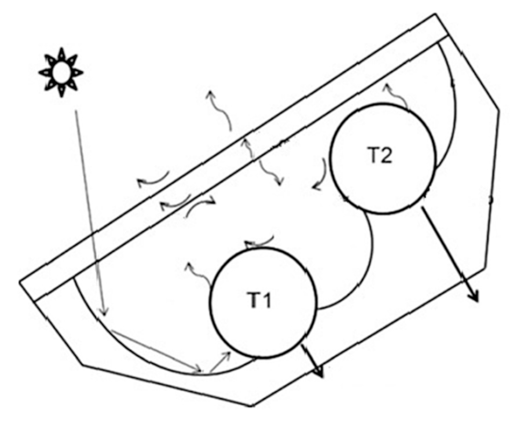
Kessentini and Bouden [63] analyzed the ICS with asymmetrical CPC reflectors, a double-glazed cover, and double storage tanks, T1 and T2 (Figure 30). Their numerical simulation study showed that the ICS solar water heater with two storage tanks has a higher efficiency of solar energy utilization, and the double-glazed cover performs better than a single glass cover for an ICS solar water heater during night and daytime operation.
4.3. Summary
Based on the above analysis, the characteristics of four types of tubular absorber CPC are compared in Table 5.
The characteristics of four tubular absorber CPC modules are compared in Table 6.
5. Application of Tubular Absorber CPC
5.1. High.-Temperature Solar Thermal Utilization
The CPC can be used in medium- and high-temperature solar energy systems as the secondary reflector, such as a parabolic through a solar collector, dish solar collector, tower solar collector, or Fresnel solar collector, for increasing the concentration ratio and reducing the accuracy requirement.
The main advantages are as follows:
- The flux distribution at the absorber can be made more uniform and reduce hot spots;
- The concentration ratio is increased, by typically a factor of 2. The requirements for mirror accuracy and tracking accuracy are reduced if the concentration ratio is constant. Rabl et al. [12] found second-stage concentrators of the CPC type to be very cost-effective in line focus systems.
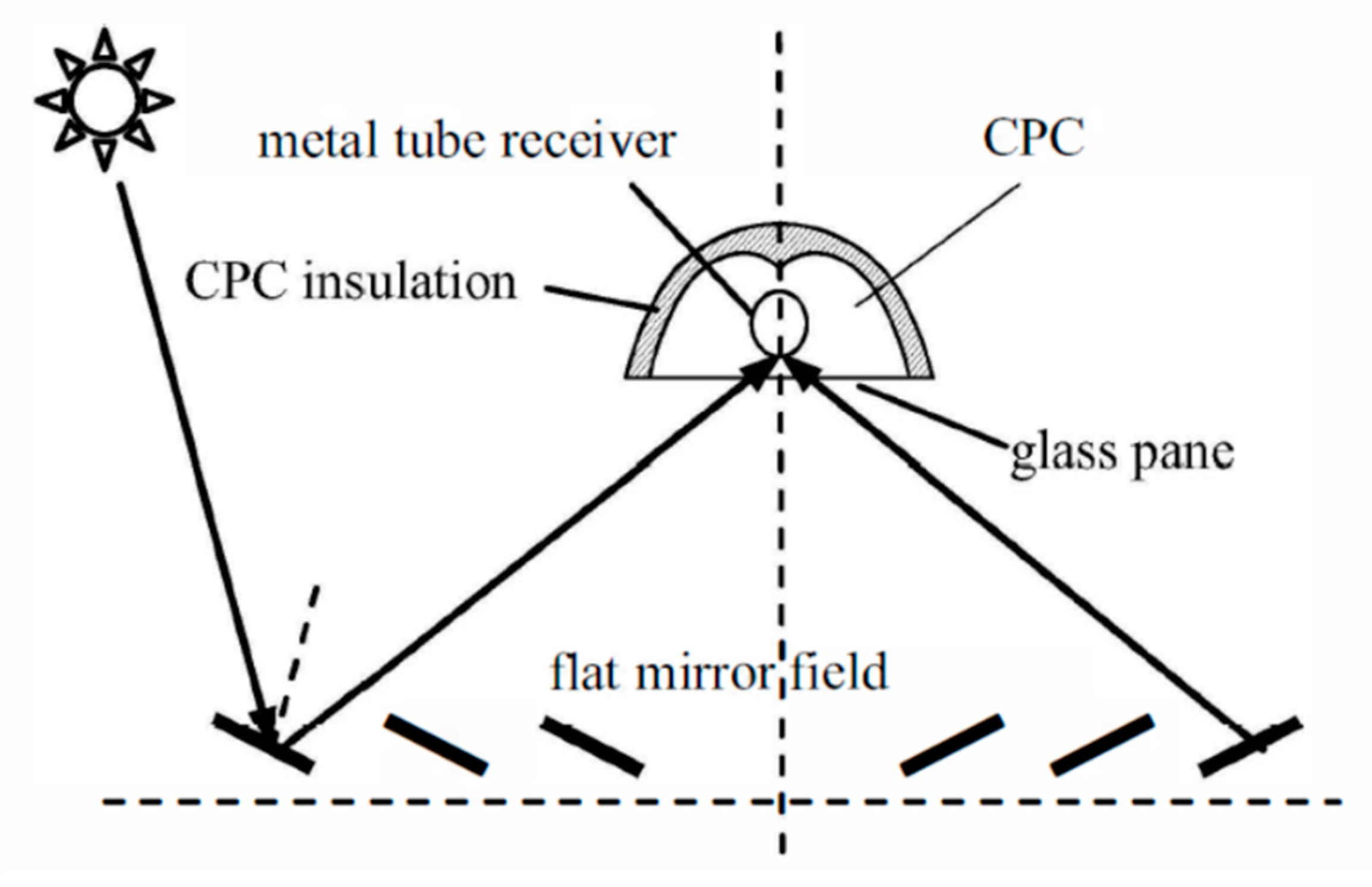
Yanhua et al. [64] investigated the thermal performance of a Fresnel reflector working with a CPC (Figure 31), which constitutes a linear Fresnel reflector (LFR) concentrator with a flat mirror field on ground, reflecting solar radiation to the CPC and metal tube receiver.
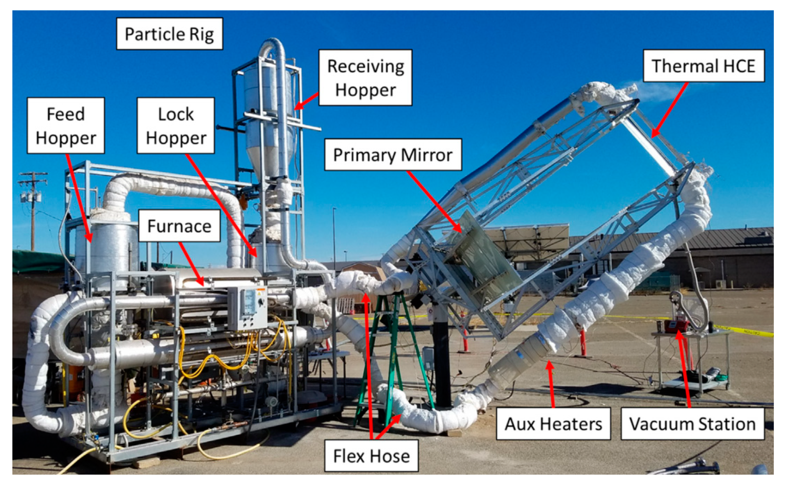
A two-stage high-concentration collector was developed with 50× concentration on the absorber using a parabolic trough and a secondary compound parabolic concentrator (Figure 32). A heat collecting element (HCE) with a secondary CPC reflector and thermal absorber encased in an evacuated glass tube was used. An experiment was performed using a suspended particulate heat transfer fluid demonstrating that the collector had a 63% optical efficiency and a 40% thermal efficiency at 650 °C [65,66].
5.2. Building-Integrated Solar System (BISS)
The wall-mounted collector with half-sided CPCs was introduced by Yu et al. [67] (Figure 33), which had a higher concentration ratio in winter and lower concentration ratio in summer. The average concentration ratio was higher than that of the symmetric CPC. This wall-mounted collector had a higher stagnation temperature and lower price.
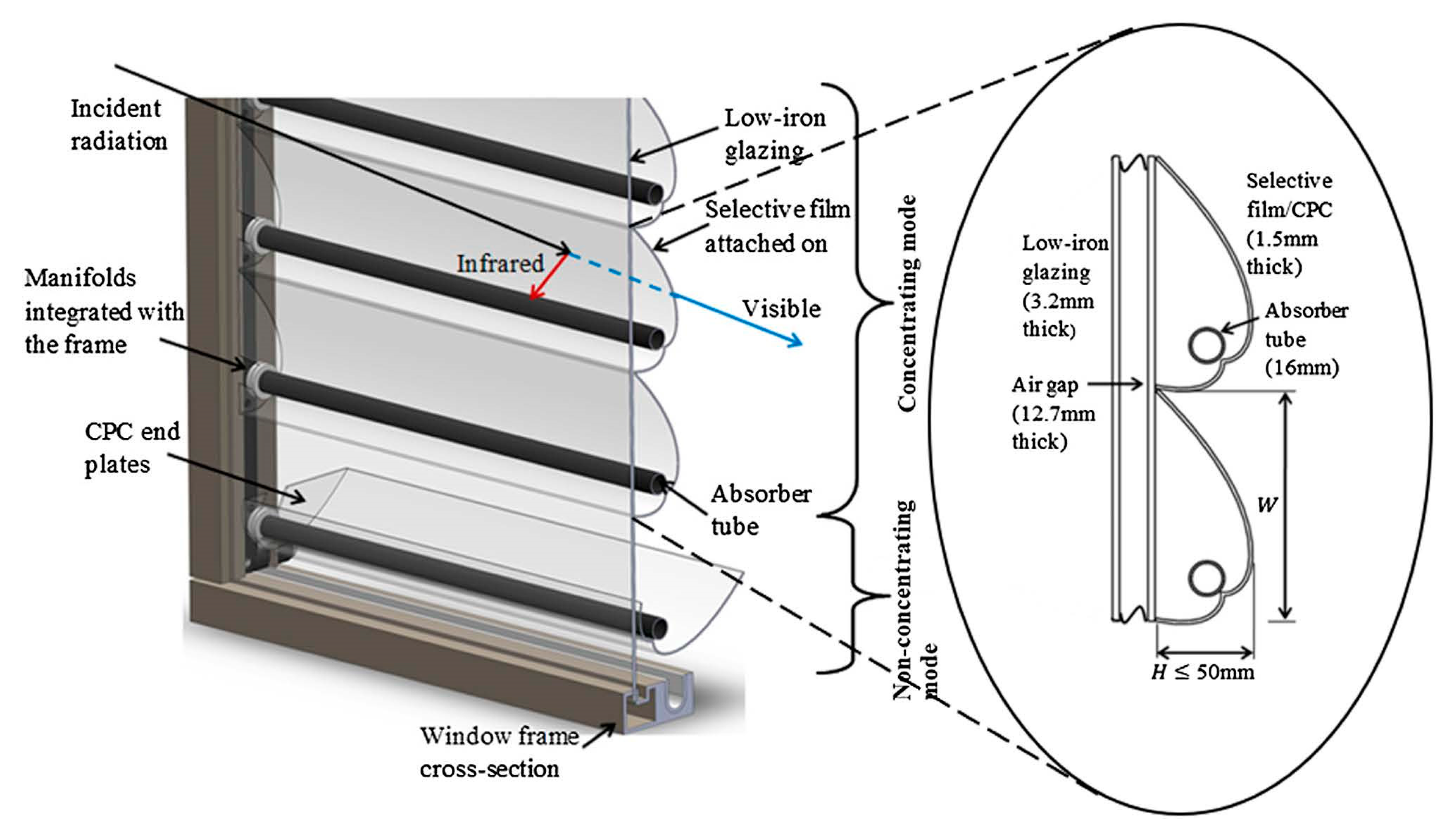
A hybrid solar window was introduced by Ulavi et al. [68], which consists of 2D CPCs and a tubular absorber, as shown in Figure 34. The solar window provides heating in addition to providing lighting and ventilation. The infrared portion of the solar spectrum is reflected and concentrated onto a tubular absorber by a wavelength-selective film and CPC, and the visible portion of the spectrum is transmitted into the interior space. The annual thermal efficiency of the double-glazed solar window with the CPC is 24–26% based on use in Minneapolis, USA.
5.3. Applied to Photovoltaics (PV)/T System
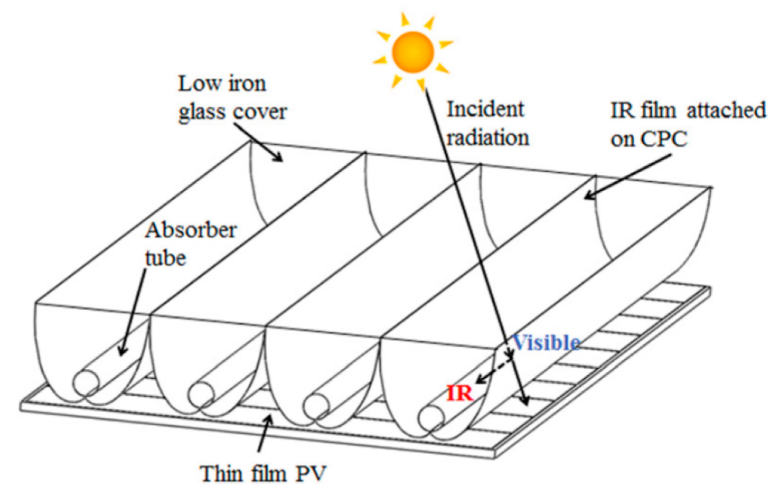
A solar thermal system with a CPC can also be combined with photovoltaics (PV). A non-tracking hybrid PV/T with a wavelength-selective film is shown in Figure 35. The IR part of the solar spectrum is directly absorbed by the tubular absorber of the CPC by the wavelength-selective film, and the visible part is transmitted to the thin-film PV module. This hybrid PV/T collector achieves a total energy output conversion efficiency of up to 20% compared to the independent PV or solar collector, as it can take advantage of longer wavelengths of solar radiation, resulting in an annual thermal efficiency of 31% [69].
5.4. Refrigeration
A tubular absorber CPC can efficiently heat a working fluid from 80 °C to 150 °C, which is suitable for single-effect and double-effect absorption refrigerators.
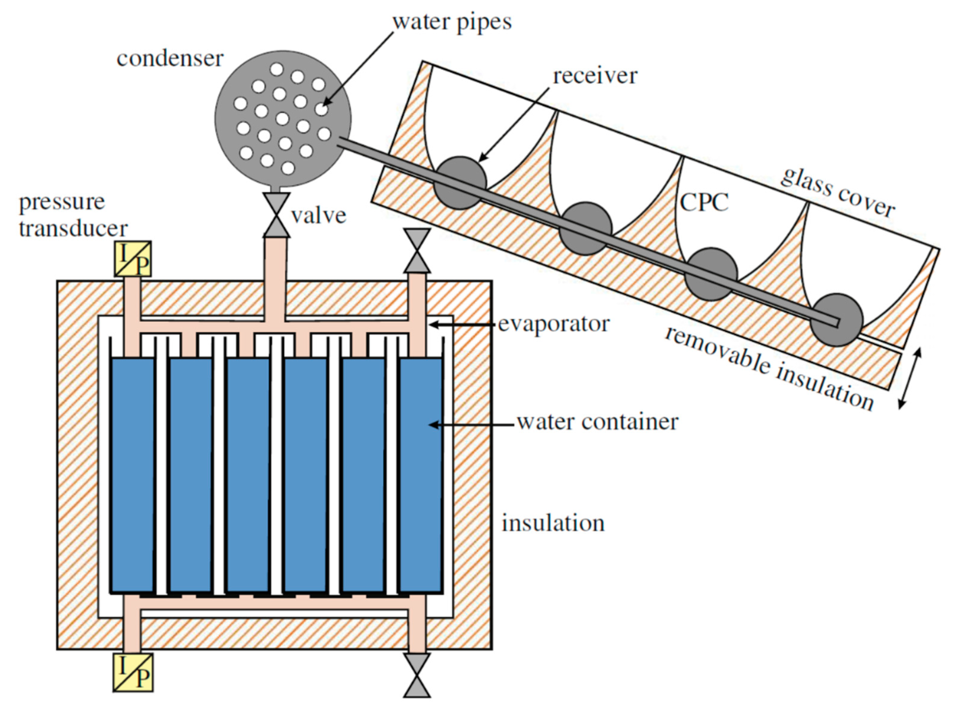
Manuel et al. [70] presented a solid-sorption refrigeration system using a methanol-activated carbon pair and a CPC solar collector (Figure 36). A model was built based on thermal exchange parameters to the main elements (generator/reactor, condenser, evaporator, and cold box) of a previously tested unit, which can be used to estimate the performance of such refrigeration systems.
A solar thermal cooling system with a novel non-tracking external compound parabolic concentrator has been running for two cooling seasons (2011 and summer 2012). Operating data show that the operating temperature of the XCPC collector array can be maintained at 160–200 °C. The average daily solar energy efficiency was 36.7%, the instantaneous efficiency was as high as 40%, and the daily solar coefficient of performance (COP) of the entire system was 0.363 [70].
5.5. Hydrogen Production
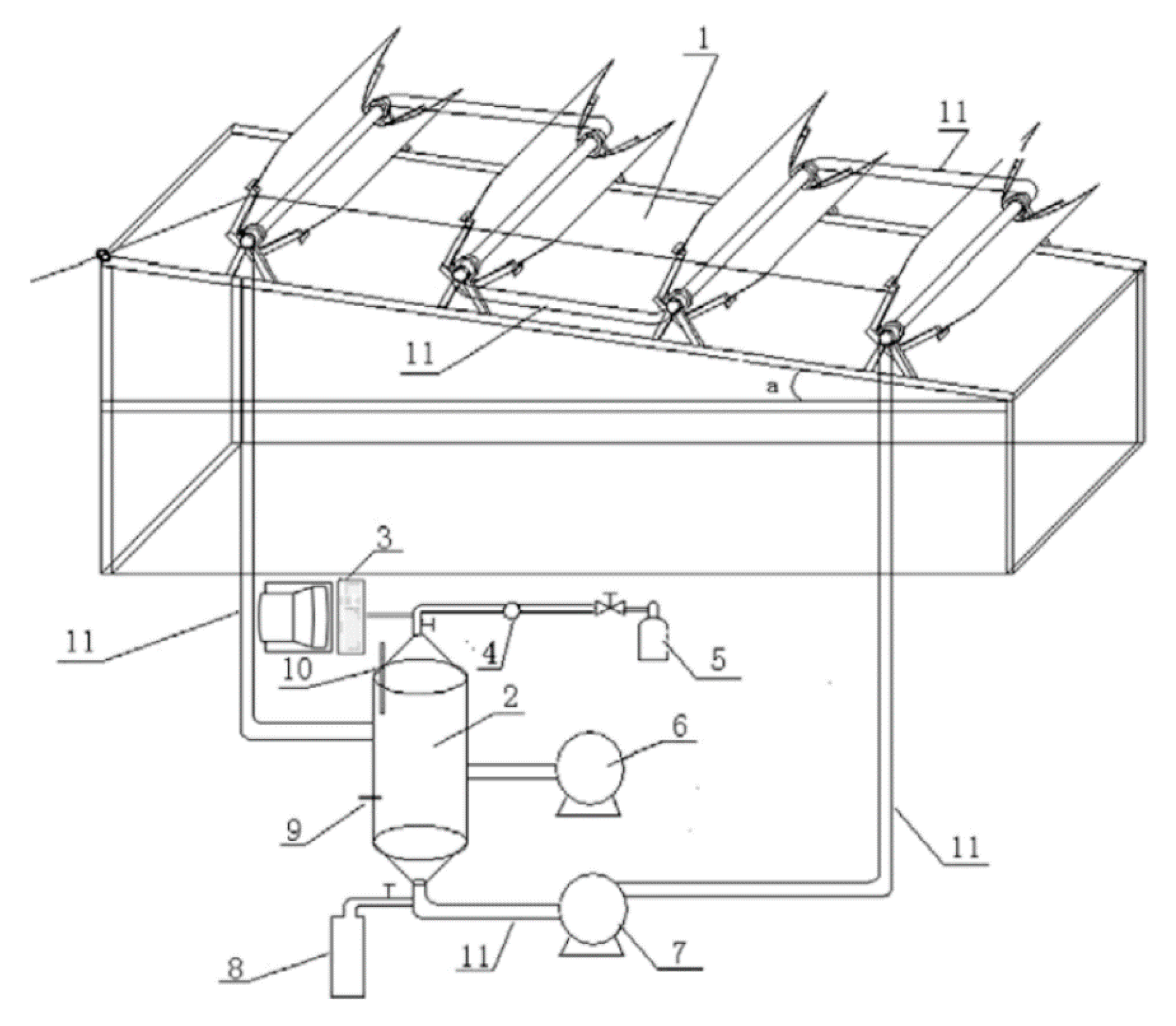
A photocatalytic hydrogen production solar reactor based on a CPC has been designed by Jing et al. [71]. The design and optimization of this reactor with the CPC are discussed in detail (Figure 37). Preliminary results indicate that efficient photocatalytic hydrogen production can be accomplished by coupling a tubular reactor to a CPC concentrator.
5.6. Distillation/Desalination
Pearce and Denkenberger [72] studied a solar distiller with a CPC reflector. The results of their study showed that for a solar distiller with CPC, the production per unit area was increased by about three times per day, and the cost was only increased by about 10%, indicating that a CPC has significant economic advantages in the production of solar distilled water.
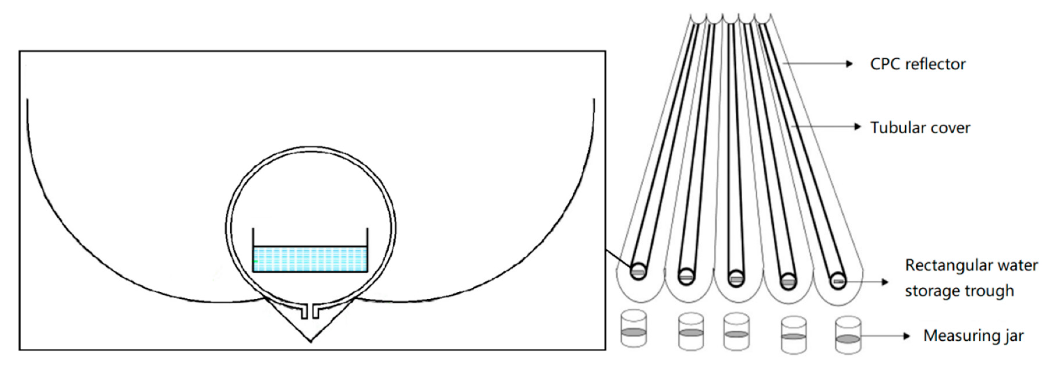
Arunkumar and Velraj [73] studied a CPC-assisted tubular solar distiller, which consisted of a CPC reflector, tubular cover, and rectangular water storage trough (Figure 38). The results of the study showed that the solar distiller of this structure costs slightly more but increases the overall efficiency and distilled water yield.
5.7. Applied to Photo-Degradation of Wastewater
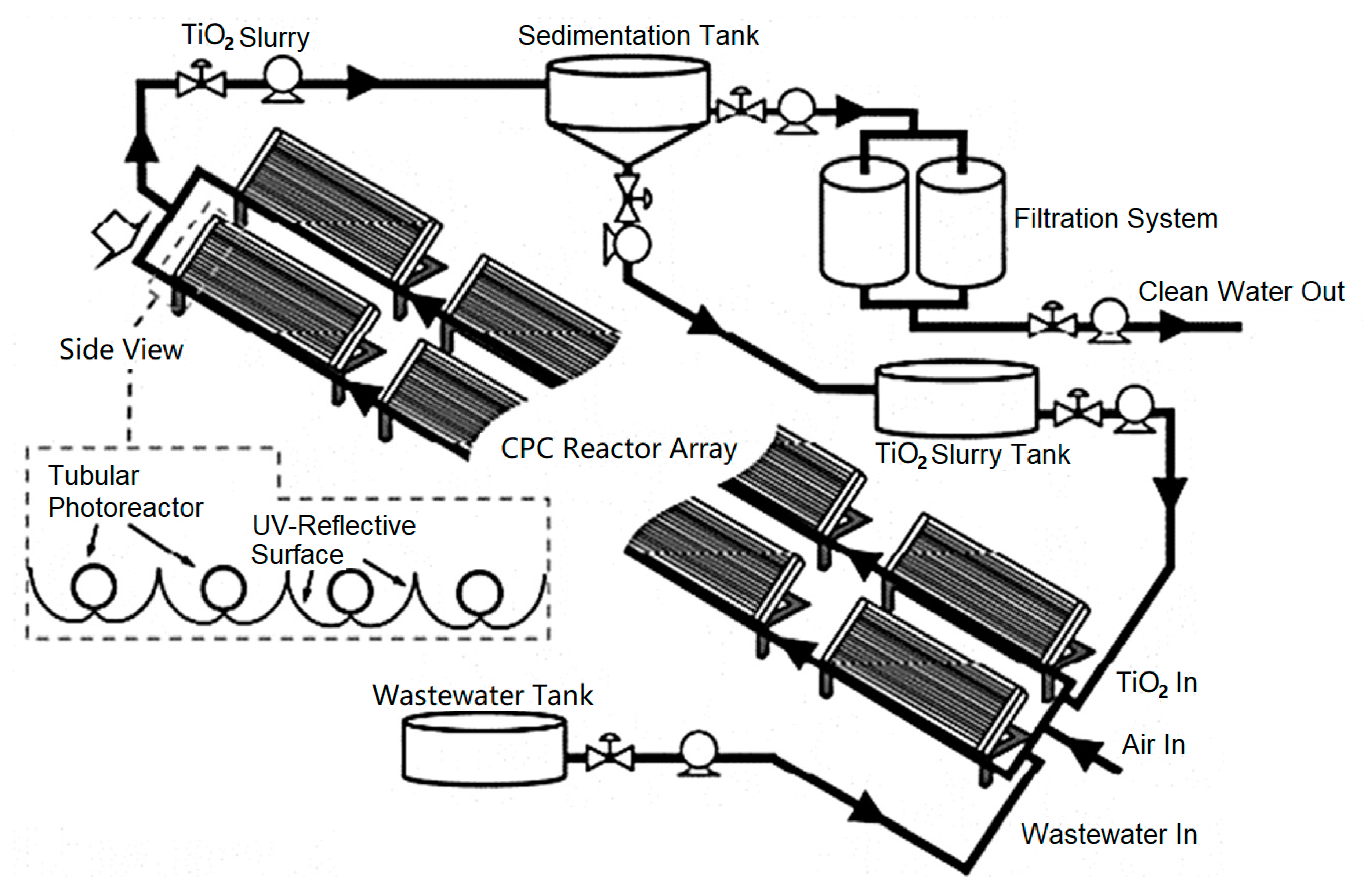
Tanveer at al. [75] studied the design, application, and operating parameters of the CPC, and proved that the CPC is more suitable for the photo-degradation of wastewater than other concentrating collectors (Figure 41). Details of CPC design parameters such as reflective surface, absorbing tube diameter, absorbing tube material, acceptance angle, and core operational parameters like photo-catalyst types and their optimum concentration, light intensity, and pH have been presented [75,76].
5.8. Summary
Based on the above analysis, the characteristics of a tubular absorber CPC module in application areas are given in Table 7.
6. Conclusions
A comprehensive review on recent research progress and developments of the tubular absorber CPC has been presented. The concept and design principles have been presented, including recent modifications and analyses on two-dimensional profile types, as well as recent new design concepts and improvements on the CPC structure.
Based on the state-of-the-art on solar thermal applications of the tubular absorber CPC in both domestic and industrial aspects, the main progress on tubular absorber CPC applications was presented.
The main observations from the review are the following:
- (1)
- The tubular absorber CPC is diverse, efficient, systematic, and especially suitable for industrial and other medium-temperature heat applications;
- (2)
- There is no “perfect CPC”, as the acceptance angle and the concentration ratio cannot be improved at the same time. Therefore, the most suitable CPC curve and structure form need to be chosen according to the purpose and requirements of the application;
- (3)
- Regarding the efficiency of tubular CPCs, due to differences in the calculation methods and basis of efficiency in the literature, no comparative analysis was made in this article, but improving the efficiency of the CPC will still be an important research direction;
- (4)
- Better integration of the tubular CPC with the heat utilization system, while reducing the manufacturing cost and system integration cost, will be important in order to further commercialize the CPC technology;
- (5)
- For low- and medium-temperature collectors, reducing the investment costs and maintenance and improving operational stability will be important. Through the scaling-up and standardization of CPC products, these challenges will also be gradually mitigated;
- (6)
- The research interest on tube CPC collectors, heat pipe CPCs, internal and external concentrating combined CPC, and TCPC modules is increasing;
- (7)
- Main applications will include building-integrated solar systems, industrial thermal energy-saving transformation, and refrigeration applications.
Author Contributions
Conceptualization, C.J., L.Y. and K.L.; methodology, L.Y., J.W., and Y.Z.; software, C.J. and L.Y.; validation, S.Y. and K.L.; formal analysis, L.Y.; investigation, K.L.; resources, L.Y.; data curation, S.Y.; writing—original draft preparation, C.J., K.L. and L.Y.; writing—review and editing, C.J., L.Y. and P.D.L.; visualization, L.Y.; supervision, J.W., P.D.L. and Y.Z.; project administration, J.W. and Y.Z.; funding acquisition, J.W. All authors have read and agreed to the published version of the manuscript.
Funding
This research was funded by the National Natural Science Foundation of China, grant number No. 51736006.
Acknowledgments
The authors want to thankfully acknowledge Ningning Huang, Zhicheng Xu for his contribution to this work.
Conflicts of Interest
The authors declare no conflict of interest.
Nomenclature
| BISS | Building-integrated solar system |
| COP | Coefficient of performance |
| CPC | Compound parabolic concentrator |
| CTC | Cylindrical trough collector |
| ETC | Evacuated tube collector |
| FE | Flux efficiency |
| FMHPA | Flat micro-heat pipe arrays |
| FPC | Flat-plate collector |
| FPTU | Flat-plate thermosiphon units |
| HCE | Heat-collecting element |
| HFC | Heliostat field collector |
| ICPC | Integrated CPC reflector |
| ICS | Integrated collector storage |
| IEA | International energy agency |
| LFR | Linear Fresnel reflector |
| PDR | Parabolic dish reflector |
| PHP | Pulsating heat pipe |
| PTC | Parabolic trough collector |
| PV | Photovoltaic |
| PV/T | Photovoltaic/thermal |
| SHC | Solar heating and cooling |
| SPETC | Single-pass evacuated tubular collector |
| TCPC | Tracking compound parabolic concentrating |
| XCPC | External compound parabolic concentrators |
| C | Concentration ratio |
| Cmax | Maximum concentration ratio |
| Ct | CPC truncation ratio |
| g | Displacement deviation of the receiver or reflector |
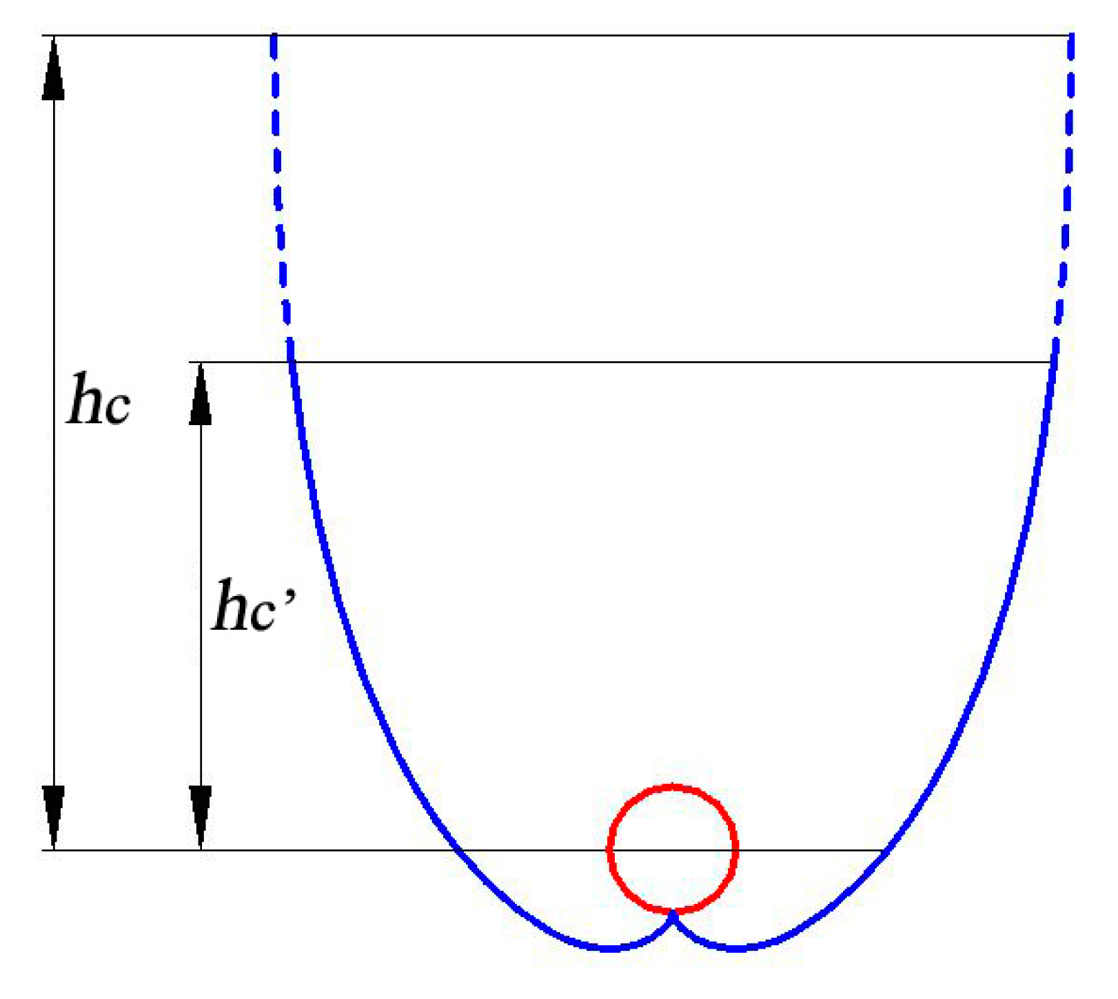
| hc | Height of CPC |
| hc’ | Reduced height by truncating the CPC |
| I | Curve segment |
| κ | Dimensionless parameter of reflector translation |
| L | Optical loss |
| Nmin | Reference average number of reflections, 1–1/C |
| r | Radius of tubular absorber |
| t | Angle variable parameter |
| θ | Angle of incident light |
| θmax | Maximum half acceptance angle |
| θa | Acceptance half angle |
| ω | Rotation angle of reflector |
| λu | Dimensionless number of absorber position offset |
References
- Tabor, H. Stationary mirror systems for solar collectors. Sol. Energy 1958, 2, 27–33. [Google Scholar] [CrossRef]
- Hinterberger, H.; Winston, R. Efficient light coupler for threshold Čerenkov counters. Rev. Sci. Instrum. 1966, 37, 1094–1095. [Google Scholar] [CrossRef]
- Winston, R.; Hinterberger, H. Principles of Cylindrical Concentrators for Solar Energy; Argonne National Laboratory: Lemont, IL, USA, 1974. [Google Scholar]
- Winston, R. Principles of solar concentrators of a novel design. Sol. Energy 1974, 16, 89–95. [Google Scholar] [CrossRef]
- Rabl, A. Comparison of solar concentrators. Sol. Energy 1976, 18, 93–111. [Google Scholar] [CrossRef]
- Rabl, A. Optical and thermal properties of compound parabolic concentrators. Sol. Energy 1976, 18, 497–511. [Google Scholar] [CrossRef]
- Welford, W.T.; Winston, R. Optics of Nonimaging Concentrators: Light and Solar Energy; Academic Press: Cambridge, MA, USA, 1978. [Google Scholar]
- Ortabasi, U.; Buehl, W.M. An internal cusp reflector for an evacuated tubular heat pipe solar thermal collector. Sol. Energy 1980, 25, 67–78. [Google Scholar] [CrossRef]
- McIntire, W.R. Truncation of nonimaging cusp concentrators. Sol. Energy 1979, 23, 351–355. [Google Scholar] [CrossRef]
- McIntire, W.R. New reflector design which avoids losses through gaps between tubular absorbers and reflectors. Sol. Energy 1980, 25, 215–220. [Google Scholar] [CrossRef]
- McIntire, W.R. Design parameters for concentrators without gap losses. Sol. Energy 1984, 32, 439–441. [Google Scholar] [CrossRef]
- Rabl, A.; Goodman, N.B.; Winston, R. Practical design considerations for CPC solar collectors. Sol. Energy 1979, 22, 373–381. [Google Scholar] [CrossRef]
- Collares-Pereira, M.; O’Gallagher, J.O.; Rabl, A. Approximations to the CPC-a comment on recent papers by Canning and by Shapiro. Sol. Energy USA 1978, 21, 245–246. [Google Scholar] [CrossRef]
- Hsieh, C.K. Thermal analysis of CPC collectors. Sol. Energy 1981, 27, 19–29. [Google Scholar] [CrossRef]
- Kothdiwala, A.F.; Norton, B.; Eames, P.C. The effect of variation of angle of inclination on the performance of low-concentration-ratio compound parabolic concentrating solar collectors. Sol. Energy 1995, 55, 301–309. [Google Scholar] [CrossRef]
- Khonkar, H.; Sayigh, A. Optimization of the tubular absorber using a compound parabolic concentrator. Renew. Energy 1995, 6, 17–21. [Google Scholar] [CrossRef]
- Fraidenraich, N.; De Lima, R.D.C.; Tiba, C.; Barbosa, E.D.S. Simulation model of a CPC collector with temperature-dependent heat loss coefficient. Sol. Energy 1999, 65, 99–110. [Google Scholar] [CrossRef]
- Oommen, R.; Jayaraman, S. Development and performance analysis of compound parabolic solar concentrators with reduced gap losses–oversized reflector. Energy Convers. Manag. 2001, 42, 1379–1399. [Google Scholar] [CrossRef]
- Oommen, R.; Jayaraman, S. Development and performance analysis of compound parabolic solar concentrators with reduced gap losses—‘V’ groove reflector. Renew. Energy 2002, 27, 259–275. [Google Scholar] [CrossRef]
- Baig, M.N.; Durrani, A.K.; Tariq, A. CPC-trough—Compound parabolic collector for cost efficient low temperature applications. In Proceedings of the ISES World Congress 2007, Vol. I–Vol. V; Springer: Berlin, Germany, 2008; pp. 603–607. [Google Scholar]
- Buttinger, F.; Beikircher, T.; Pröll, M.; Schölkopf, W. Development of a new flat stationary evacuated CPC-collector for process heat applications. Sol. Energy 2010, 84, 1166–1174. [Google Scholar] [CrossRef]
- Weiss, W.; Rommel, M. Process heat collectors. State Art Task 2008, 33, 1–58. [Google Scholar]
- Brunold, S.; Frey, R.; Frei, U. Comparison of three different collectors for process heat applications. In Optical Materials Technology for Energy Efficiency and Solar Energy Conversion XIII; International Society for Optics and Photonics: Bellingham, WA, USA, 1994; pp. 107–118. [Google Scholar]
- Fernández-García, A.; Zarza, E.; Valenzuela, L.; Pérez, M. Parabolic-trough solar collectors and their applications. Renew. Sustain. Energy Rev. 2010, 14, 1695–1721. [Google Scholar] [CrossRef]
- IEA. Solar Energy: Mapping the Road Ahead; IEA: Paris, France, 2019. [Google Scholar]
- Kalogirou, S.A. Solar Energy Engineering: Processes and Systems; Academic Press: New York, NY, USA, 2013. [Google Scholar]
- Wang, J.; Yu, L.; Jiang, C.; Yang, S.; Liu, T. Optical analysis of solar collector with new V-shaped CPC. Sol. Energy 2016, 135, 780–785. [Google Scholar] [CrossRef]
- Duffie, J.A.; Beckman, W.A. Solar Engineering of Thermal Processes; John Wiley & Sons: New York, NY, USA, 2013. [Google Scholar]
- Carvalho, M.J.; Collares-Pereira, M.; Gordon, J.M.; Rabl, A. Truncation of CPC solar collectors and its effect on energy collection. Sol. Energy 1985, 35, 393–399. [Google Scholar] [CrossRef]
- Yu, L. Study on Solar Collector with Compound Parabolic Concentrator. Master’s Thesis, Southeast University, Nanjing, China, 2011. [Google Scholar]
- Xu, R.; Ma, Y.; Yan, M.; Zhang, C.; Xu, S.; Wang, R. Effects of deformation of cylindrical compound parabolic concentrator (CPC) on concentration characteristics. Sol. Energy 2018, 176, 73–86. [Google Scholar] [CrossRef]
- Eames, P.C.; Norton, B. Thermal and optical consequences of the introduction of baffles into compound parabolic concentrating solar energy collector cavities. Sol. Energy 1995, 55, 139–150. [Google Scholar] [CrossRef]
- Li, X.; Dai, Y.J.; Li, Y.; Wang, R.Z. Performance investigation on a novel single-pass evacuated tube with a symmetrical compound parabolic concentrator. Sol. Energy 2013, 98, 275–289. [Google Scholar] [CrossRef]
- Widyolar, B.K.; Jiang, L.; Winston, R. Thermodynamics and the segmented compound parabolic concentrator. J. Photon. Energy 2017, 7, 28002. [Google Scholar] [CrossRef]
- Wang, J.; Yang, S.; Jiang, C.; Yan, Q.; Lund, P.D. A novel 2-stage dish concentrator with improved optical performance for concentrating solar power plants. Renew. Energy 2017, 108, 92–97. [Google Scholar] [CrossRef] [Green Version]
- Adsten, M.; Helgesson, A.; Karlsson, B. Evaluation of CPC-collector designs for stand-alone, roof-or wall installation. Sol. Energy 2005, 79, 638–647. [Google Scholar] [CrossRef]
- Yuan, H.; Zhang, H.; Xu, H.; Ji, T. Investigation on temperature Performance of internal condensing CPC collector tube with heat pipe. Water Resour. Power 2010, 10, 253–256. [Google Scholar]
- Yu, L.; Wang, J.; Zhang, Y. A compound paraboloid condenser with a combination of internal and external light. CN Patent CN201010018320.1, 13 January 2010. [Google Scholar]
- Pradhan, D.; Mitra, D.; Neogi, S. Thermal performance of a heat pipe embedded evacuated tube collector in a compound parabolic concentrator. Energy Procedia 2016, 90, 217–226. [Google Scholar] [CrossRef]
- Xu, R.J.; Zhang, X.H.; Wang, R.X.; Xu, S.H.; Wang, H.S. Experimental investigation of a solar collector integrated with a pulsating heat pipe and a compound parabolic concentrator. Energy Convers. Manag. 2017, 148, 68–77. [Google Scholar] [CrossRef]
- Zhu, T.; Diao, Y.; Zhao, Y.; Li, F. Thermal performance of a new CPC solar air collector with flat micro-heat pipe arrays. Appl. Therm. Eng. 2016, 98, 1201–1213. [Google Scholar] [CrossRef]
- Wang, P.; Guan, H.; Liu, Z.; Wang, G.; Zhao, F.; Xiao, H. High temperature collecting performance of a new all-glass evacuated tubular solar air heater with U-shaped tube heat exchanger. Energy Convers. Manag. 2014, 77, 315–323. [Google Scholar] [CrossRef] [Green Version]
- Nayak, J.K.; Amer, E.H. Experimental and theoretical evaluation of dynamic test procedures for solar flat-plate collectors. Sol. Energy 2000, 69, 377–401. [Google Scholar] [CrossRef]
- Qi, T. Thermal performance of the U-type evacuated glass tubular solar collector. Build. Energy Environ. 2007, 26, 51–54. [Google Scholar]
- Kim, Y.; Seo, T. Thermal performances comparisons of the glass evacuated tube solar collectors with shapes of absorber tube. Renew. Energy 2007, 32, 772–795. [Google Scholar] [CrossRef]
- Korres, D.; Tzivanidis, C. A new mini-CPC with a U-type evacuated tube under thermal and optical investigation. Renew. Energy 2018, 128, 529–540. [Google Scholar] [CrossRef]
- Mishra, R.K.; Garg, V.; Tiwari, G.N. Energy matrices of U-shaped evacuated tubular collector (ETC) integrated with compound parabolic concentrator (CPC). Sol. Energy 2017, 153, 531–539. [Google Scholar] [CrossRef]
- Zhang, L.; Yu, Z.; Fan, L.; Wang, W.; Chen, H.; Hu, Y.; Fan, J.; Ni, M.; Cen, K. An experimental investigation of the heat losses of a U-type solar heat pipe receiver of a parabolic trough collector-based natural circulation steam generation system. Renew. Energy 2013, 57, 262–268. [Google Scholar] [CrossRef]
- Li, X.; Dai, Y.J.; Li, Y.; Wang, R.Z. Comparative study on two novel intermediate temperature CPC solar collectors with the U-shape evacuated tubular absorber. Sol. Energy 2013, 93, 220–234. [Google Scholar] [CrossRef]
- Kim, Y.S.; Balkoski, K.; Jiang, L.; Winston, R. Efficient stationary solar thermal collector systems operating at a medium-temperature range. Appl. Energy 2013, 111, 1071–1079. [Google Scholar] [CrossRef]
- Duong, V.; Diaz, G. Carbon dioxide as working fluid for medium and high-temperature concentrated solar thermal systems. AIMS Energy 2014, 1, 99–115. [Google Scholar] [CrossRef] [Green Version]
- Abdullahi, B.; Al-Dadah, R.K.; Mouhmud, S. Optical performance of double receiver compound parabolic concentrator. Energy Procedia 2014, 61, 2625–2628. [Google Scholar] [CrossRef] [Green Version]
- Widyolar, B.; Jiang, L.; Ferry, J.; Winston, R. Non-tracking East-West XCPC solar thermal collector for 200 celsius applications. Appl. Energy 2018, 216, 521–533. [Google Scholar] [CrossRef]
- Jiang, L.; Widyolar, B.; Winston, R. Characterization of novel mid-temperature CPC solar thermal collectors. Energy Procedia 2015, 70, 65–70. [Google Scholar] [CrossRef] [Green Version]
- Balkoski, K. Performance Analysis of Medium Temperature Non-Tracking Solar Thermal Concentrators. Ph.D. Thesis, UC Merced, Merced, CA, USA, 2011. [Google Scholar]
- Duff, W.S.; Winston, R.; O Gallagher, J.J.; Bergquam, J.; Henkel, T. Performance of the Sacramento demonstration ICPC collector and double effect chiller. Sol. Energy 2004, 76, 175–180. [Google Scholar] [CrossRef]
- Wang, Y.; Zhu, Y.; Chen, H.; Zhang, X.; Yang, L.; Liao, C. Performance analysis of a novel sun-tracking CPC heat pipe evacuated tubular collector. Appl. Therm. Eng. 2015, 87, 381–388. [Google Scholar] [CrossRef]
- Yu, L.; Wang, J.; Zhang, Y. Two-stage concentrating CPC. CN Patent CN201020022517.8, 13 January 2010. [Google Scholar]
- Zheng, W.; Yang, L.; Zhang, H.; You, S.; Zhu, C. Numerical and experimental investigation on a new type of compound parabolic concentrator solar collector. Energy Convers. Manag. 2016, 129, 11–22. [Google Scholar] [CrossRef]
- Pranesh, V.; Velraj, R.; Christopher, S.; Kumaresan, V. A 50 year review of basic and applied research in compound parabolic concentrating solar thermal collector for domestic and industrial applications. Sol. Energy 2019, 187, 293–340. [Google Scholar] [CrossRef]
- Souliotis, M.; Tripanagnostopoulos, Y. Experimental study of CPC type ICS solar systems. Sol. Energy 2004, 76, 389–408. [Google Scholar] [CrossRef]
- Souliotis, M.; Tripanagnostopoulos, Y. Study of the distribution of the absorbed solar radiation on the performance of a CPC-type ICS water heater. Renew. Energy 2008, 33, 846–858. [Google Scholar] [CrossRef]
- Kessentini, H.; Bouden, C. Numerical simulation, design, and construction of a double glazed compound parabolic concentrators-type integrated collector storage water heater. J. Sol. Energy Eng. 2016, 138, 14501. [Google Scholar] [CrossRef]
- Lai, Y.; Song, G.; Lu, M.; Dong, Z.; Che, S.; Ma, C. Thermal performance analysis of linear fresnel reflector concentrator with a compound parabolic cavity absorber. In Proceedings of the 2011 IEEE International Conference on Materials for Renewable Energy & Environment, Shanghai, China, 20–22 May 2011; pp. 168–172. [Google Scholar]
- Pandey, A.R.; Powers, P.E.; Haus, J.W. Experimental performance of a two-stage periodically poled lithium niobate parametric amplifier. IEEE J. Quantum Electron. 2008, 44, 203–208. [Google Scholar] [CrossRef]
- Widyolar, B.; Jiang, L.; Ferry, J.; Winston, R.; Cygan, D.; Abbasi, H. Experimental performance of a two-stage (50×) parabolic trough collector tested to 650 °C using a suspended particulate heat transfer fluid. Appl. Energy 2019, 240, 436–445. [Google Scholar] [CrossRef]
- Yu, L.; Wang, J.; Zhang, Y. A wall-mounted collector with half-sided CPCs. CN Patent CN201010153422.4, 21 April 2010. [Google Scholar]
- Ulavi, T.; Hebrink, T.; Davidson, J.H. Analysis of a hybrid solar window for building integration. Sol. Energy 2014, 105, 290–302. [Google Scholar] [CrossRef]
- Ulavi, T.U.; Davidson, J.H.; Hebrink, T. Analysis of a hybrid PV/T Concept based on wavelength selective films. In Proceedings of the ASME 2013 7th International Conference on Energy Sustainability Collocated with the ASME 2013 Heat Transfer Summer Conference and the ASME 2013 11th International Conference on Fuel Cell Science, Engineering and Technology, Minneapolis, MN, USA, 4–19 July 2013. [Google Scholar]
- González, M.I.; Rodríguez, L.R.; Lucio, J.H. Evaluation of thermal parameters and simulation of a solar-powered, solid-sorption chiller with a CPC collector. Renew. Energy 2009, 34, 570–577. [Google Scholar] [CrossRef]
- Jing, D.; Liu, H.; Zhang, X.; Zhao, L.; Guo, L. Photocatalytic hydrogen production under direct solar light in a CPC based solar reactor: Reactor design and preliminary results. Energy Convers. Manag. 2009, 50, 2919–2926. [Google Scholar] [CrossRef]
- Denkenberger, D.C.; Pearce, J.M. Compound parabolic concentrators for solar water heat pasteurization: Numerical simulation. In Proceedings of the 2006 International Conference of Solar Cooking and Food Processing, Granada, Spain, 12–16 July 2006; pp. 12–16. [Google Scholar]
- Arunkumar, T.; Velraj, R.; Denkenberger, D.C.; Sathyamurthy, R.; Kumar, K.V.; Ahsan, A. Productivity enhancements of compound parabolic concentrator tubular solar stills. Renew. Energy 2016, 88, 391–400. [Google Scholar] [CrossRef]
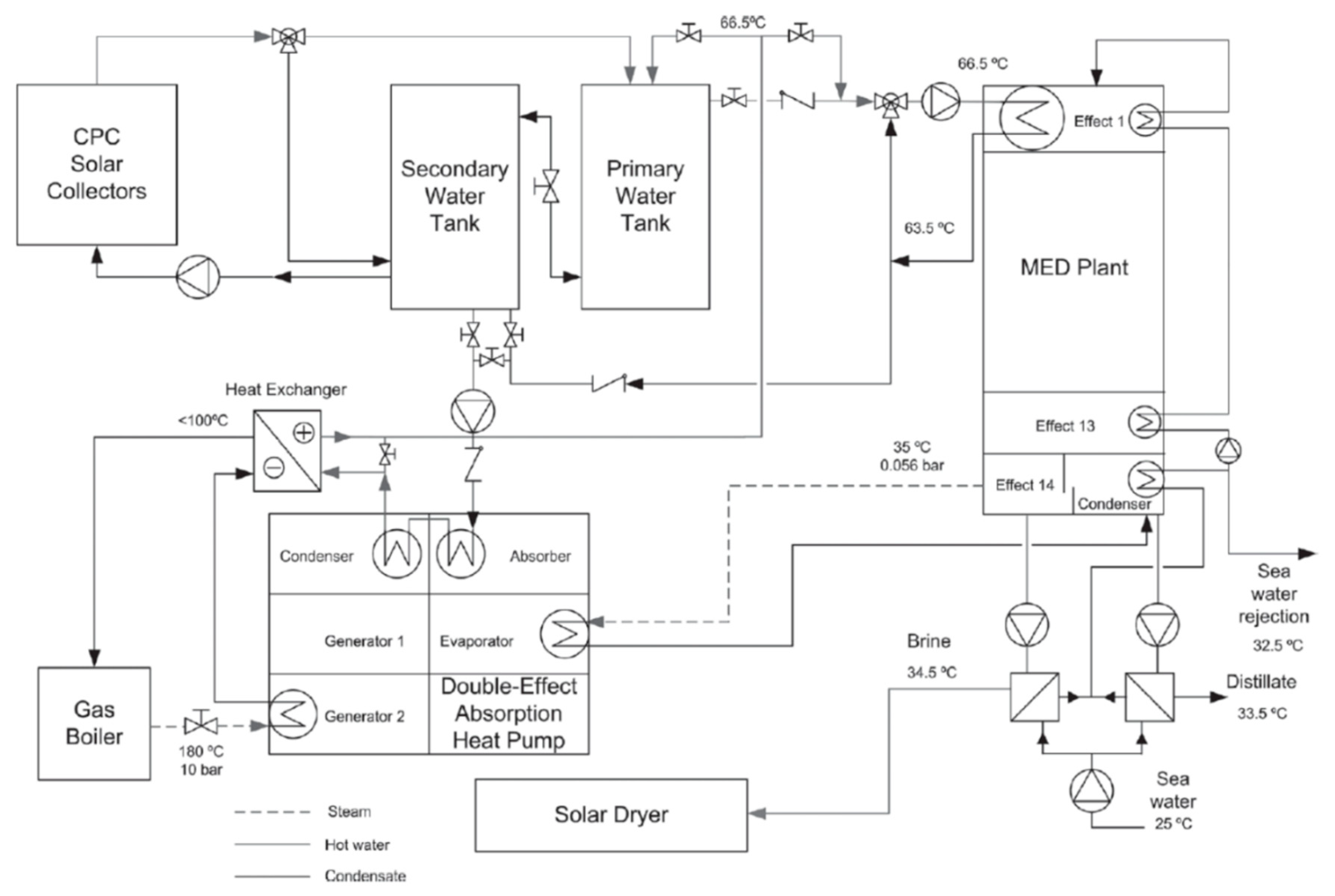
- Alarcon-Padilla, D.; Blanco-Gálvez, J.; García-Rodríguezz, L.; Gernjak, W.; Malato-Rodríguez, S. First experimental results of a new hybrid solar/gas multi-effect distillation system: The AQUASOL project. Desalination 2008, 220, 619–625. [Google Scholar] [CrossRef]
- Tanveer, M.; Guyer, G.T. Solar assisted photo degradation of wastewater by compound parabolic collectors: Review of design and operational parameters. Renew. Sustain. Energy Rev. 2013, 24, 534–543. [Google Scholar] [CrossRef]
- Tian, M.; Su, Y.; Zheng, H.; Pei, G.; Li, G.; Riffat, S. A review on the recent research progress in the compound parabolic concentrator (CPC) for solar energy applications. Renew. Sustain. Energy Rev. 2018, 82, 1272–1296. [Google Scholar] [CrossRef] [Green Version]
- Zhang, T.C.; Surampalli, R.Y.; Lai, K.C.; Hu, Z.; Tyagi, R.D.; Lo, I.M. Nanotechnologies for Water Environment Applications; American Society of Civil Engineers: New York, NY, USA, 2009. [Google Scholar]
Figure 1.
Two types of curves for tubular absorber compound parabolic concentrator (CPC): (a) Involute segment CPC profile; (b) curved segment profile.
Figure 1.
Two types of curves for tubular absorber compound parabolic concentrator (CPC): (a) Involute segment CPC profile; (b) curved segment profile.

Figure 2.
Four ways to create gaps in CPC. (a) Reducing the radius of the tubular absorber; (b) cutting the sharp corner of the reflector; (c) changing the shape of the absorber; (d) moving the absorber up [27].
Figure 2.
Four ways to create gaps in CPC. (a) Reducing the radius of the tubular absorber; (b) cutting the sharp corner of the reflector; (c) changing the shape of the absorber; (d) moving the absorber up [27].

Figure 3.
Schematic of the new V-shaped CPC: (a) Single V-shaped CPC; (b) multi V-shaped CPC [27].
Figure 3.
Schematic of the new V-shaped CPC: (a) Single V-shaped CPC; (b) multi V-shaped CPC [27].

Figure 4.
Overall efficiency curves of CPCs with different gap [27].
Figure 4.
Overall efficiency curves of CPCs with different gap [27].

Figure 5.
Relationship between concentrating ratio, average number of reflections, and truncation ratio [28].
Figure 5.
Relationship between concentrating ratio, average number of reflections, and truncation ratio [28].

Figure 6.
Schematic of truncated CPC.

Figure 7.
Relationship between concentrating ratio, acceptance angle, and truncation ratio [30].
Figure 7.
Relationship between concentrating ratio, acceptance angle, and truncation ratio [30].

Figure 8.
The average heat flux density on the absorber with rotation of the CPC reflector (C = 4, Ct = 0.5) [31].
Figure 8.
The average heat flux density on the absorber with rotation of the CPC reflector (C = 4, Ct = 0.5) [31].

Figure 9.
The average heat flux density on the absorber with translation of the CPC reflector (C = 4, Ct = 0.5) [31].
Figure 9.
The average heat flux density on the absorber with translation of the CPC reflector (C = 4, Ct = 0.5) [31].

Figure 10.
The average heat flux density on the absorber with movement of the absorber (Ct = 0.5) [31].
Figure 10.
The average heat flux density on the absorber with movement of the absorber (Ct = 0.5) [31].

Figure 11.
Common external concentrating CPC products.

Figure 12.
External concentrating tubular absorber CPC with baffle [32].
Figure 12.
External concentrating tubular absorber CPC with baffle [32].

Figure 13.
Schematic diagram of the CPC with single-pass evacuated tubular collector (left: Cross-section; right: Experimental setup) [33].
Figure 13.
Schematic diagram of the CPC with single-pass evacuated tubular collector (left: Cross-section; right: Experimental setup) [33].

Figure 14.
Methods to generate approximate profiles by using segment CPC [34].
Figure 14.
Methods to generate approximate profiles by using segment CPC [34].

Figure 15.
Schematic of an evacuated tube with internal CPC: (a) Cross-sectional view; (b) structure diagram [37].
Figure 15.
Schematic of an evacuated tube with internal CPC: (a) Cross-sectional view; (b) structure diagram [37].

Figure 16.
Collector with new V-shaped CPC, heat pipe, and inner reflector [30].
Figure 16.
Collector with new V-shaped CPC, heat pipe, and inner reflector [30].

Figure 17.
Schematic diagram of internal and external concentrating combined CPC (left: 3-D model, right: Cross-sectional view) [38].
Figure 17.
Schematic diagram of internal and external concentrating combined CPC (left: 3-D model, right: Cross-sectional view) [38].

Figure 18.
View of a CPC with evacuated tube heat pipe [39].
Figure 18.
View of a CPC with evacuated tube heat pipe [39].

Figure 19.
Schematic of the CPC with flat micro-heat pipe arrays (FMHPA) (left: Heating collecting unit; right: Cylinder receiver) [41].
Figure 19.
Schematic of the CPC with flat micro-heat pipe arrays (FMHPA) (left: Heating collecting unit; right: Cylinder receiver) [41].

Figure 20.
External concentrating CPC with U-shaped pipe [49].
Figure 20.
External concentrating CPC with U-shaped pipe [49].

Figure 21.
Schematic of CPC with coaxial pipe [51].
Figure 21.
Schematic of CPC with coaxial pipe [51].

Figure 22.
Ray-tracing simulation on single (upper left), double horizontal (upper right), vertical (lower left), and elliptical receiver (lower right) [52].
Figure 22.
Ray-tracing simulation on single (upper left), double horizontal (upper right), vertical (lower left), and elliptical receiver (lower right) [52].

Figure 23.
Ray-trace analysis of 40° E/W collector with pentagon absorber for (a) normal, (b) 20°, and (c) 40° incidence [53].
Figure 23.
Ray-trace analysis of 40° E/W collector with pentagon absorber for (a) normal, (b) 20°, and (c) 40° incidence [53].

Figure 24.
New integrated CPC (ICPC) design showing vertical and horizontal fin orientations [54].
Figure 24.
New integrated CPC (ICPC) design showing vertical and horizontal fin orientations [54].

Figure 25.
Schematic view of the east–west axis TCPC.

Figure 26.
Schematic view of the north–south-axis TCPC (left: 3-D model; right: Experimental setup) [57].
Figure 26.
Schematic view of the north–south-axis TCPC (left: 3-D model; right: Experimental setup) [57].

Figure 27.
Schematic diagram of two-stage concentrating CPC.

Figure 28.
Schematic of the serpentine CPC configuration (left: Front view; right: Section view) [59].
Figure 28.
Schematic of the serpentine CPC configuration (left: Front view; right: Section view) [59].

Figure 29.
Cross-section of the ICS with CPC [61].
Figure 29.
Cross-section of the ICS with CPC [61].

Figure 30.
Cross-section of the ICS with CPC and double storage tanks [63].
Figure 30.
Cross-section of the ICS with CPC and double storage tanks [63].

Figure 31.
Cross-sectional view of Fresnel solar collector with CPC [64].
Figure 31.
Cross-sectional view of Fresnel solar collector with CPC [64].

Figure 32.
Experimental test platform of two-stage parabolic trough collector [66].
Figure 32.
Experimental test platform of two-stage parabolic trough collector [66].

Figure 33.
Schematic diagram of wall-mounted collector with half-sided CPCs [67].
Figure 33.
Schematic diagram of wall-mounted collector with half-sided CPCs [67].

Figure 34.
Schematic diagram of hybrid solar window [68].
Figure 34.
Schematic diagram of hybrid solar window [68].

Figure 35.
Hybrid photovoltaic (PV)/T CPC [69].
Figure 35.
Hybrid photovoltaic (PV)/T CPC [69].

Figure 36.
Schematic view of the solid-sorption chiller with CPC [70].
Figure 36.
Schematic view of the solid-sorption chiller with CPC [70].

Figure 37.
Flow chart of the photocatalytic hydrogen production solar reactor. (1) Support, (2) storage tank, (3) gas chromatography, (4) gas flow meter, (5) gas collection apparatus, (6) feeding pump, (7) circulating pump, (8) N2, (9) temperature sensor, (10) pressure sensor, and (11) connecting tube [71].

Figure 38.
Scheme of the CPC-assisted tubular solar still [73].
Figure 38.
Scheme of the CPC-assisted tubular solar still [73].

Figure 39.
Configuration of AQUASOL seawater desalination system [74].
Figure 39.
Configuration of AQUASOL seawater desalination system [74].

Figure 40.
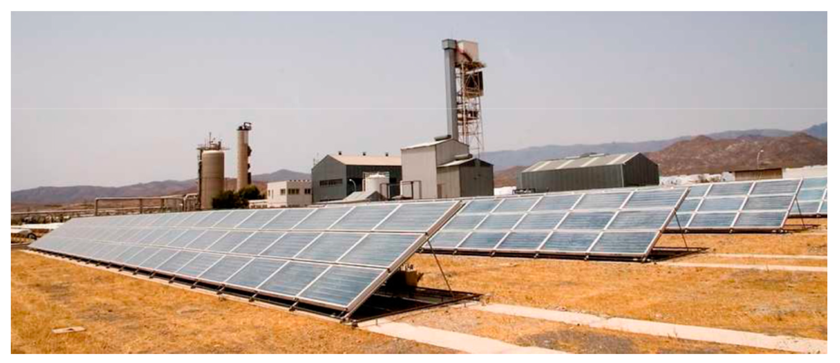
A 500 m2 stationary CPC solar collector field [74].
Figure 40.
A 500 m2 stationary CPC solar collector field [74].

Figure 41.
Schematic diagram of a photocatalytic water purification system with CPC reactor [77].
Figure 41.
Schematic diagram of a photocatalytic water purification system with CPC reactor [77].


Table 1.
Collector types for solar thermal utilization [26].
Table 1.
Collector types for solar thermal utilization [26].
| Collector Type | Absorber Type | Concentration Ratio | Indicative Temperature Range (°C) |
|---|---|---|---|
| Flat-plate collector (FPC) | Flat | 1 | 30–80 |
| Evacuated tube collector (ETC) | Flat | 1 | 50–200 |
| Stationary compound parabolic collector (CPC) | Tubular | 1–5 | 60–240 |
| Tracking compound parabolic collector (CPC) | Tubular | 5–15 | 60–300 |
| Linear Fresnel reflector (LFR) | Tubular | 10–40 | 60–250 |
| Cylindrical trough collector (CTC) | Tubular | 15–50 | 60–300 |
| Parabolic trough collector (PTC) | Tubular | 10–85 | 60–400 |
| Parabolic dish reflector (PDR) | Point | 600–2000 | 100–1500 |
| Heliostat field collector (HFC) | Point | 300–1500 | 150–2000 |
Table 2.
The recommended methods of dealing with the CPC gap.
| g/r | Methods of Dealing with the CPC Gap |
|---|---|
| 0.1–0.51 | new V-shaped CPC prevents the rays that reach the bottom surface of the CPC from escaping and the concentration ratio from reducing |
| 0.51–1 | “V”s CPC can minimize the gap loss |
| <0.2 | little difference between the approaches; truncating the corners is a simple approach |
| >0.6 | changing involute starting point can be chosen for increasing the concentration ratio |
Table 3.
Recommended truncation ratio.
| Concentration Ratio | Truncation Ratio |
|---|---|
| <2 | 0.6–0.8 |
| 2–5 | 0.4–0.6 |
| >5 | 0.2–0.4 |
Table 4.
Comparison of different types of concentrating options for tubular absorber CPC.
| Types of Concentrating Options | Advantage | Disadvantage |
|---|---|---|
| External | Simple structure and low cost Unlimited concentration ratio | Difficult to maintain and fast performance degradation High gap loss |
| Internal | Easy to maintain low gap loss | Limited concentration ratio (<2) High cost |
| Internal and External | Easy to maintain Unlimited concentration ratio low gap loss | Complex structure High cost |
Table 5.
Comparison of different absorbers of tubular absorber CPC.
| Types of Absorber | Advantage | Disadvantage |
|---|---|---|
| CPC with Heat Pipe | Flexible structure Easy to replace Low thermal resistance Anti-freezing | High cost |
| CPC with U-shaped Pipe | Simple structure Low cost | Flow resistance Slightly high flow resistance Slightly high thermal resistance Not suitable for internal concentrating CPC |
| CPC with Coaxial Pipe | Low thermal stress Uniform heat transfer rate | Higher flow resistance Easy to block Slightly high thermal resistance Not suitable for internal concentrating CPC |
| CPC with Double Tubes | Collect more solar energy | Low concentration ratio Inconvenient to place vacuum tubes |
Table 6.
Comparison of different tubular absorber CPC modules.
| Types of CPC Modules | Characteristics |
|---|---|
| TCPC collectors | Can achieve a higher concentration ratio Can be adjusted manually or automatically Lower cost General east–west axis General external concentrating CPC Already industrialized |
| Two-stage concentrating CPC | High concentration ratio Simple structure Quasi-3D CPC Unindustrialized |
| Serpentine CPC | High frost resistance No vacuum tube required Easy to maintain Slightly lower optical efficiency Pilot stage |
| ICS with CPC | Integration of heat storage and heat collection Lower cost Pilot stage Double-glazed cover performs better |
Table 7.
Summary of tubular absorber CPC modules in different application areas.
| Application Area | Characteristics |
|---|---|
| High-Temperature Solar Thermal Utilization | Secondary reflector as a linear tracking collector Increase the concentration ratio to reduce the tracking accuracy requirements Already industrialized |
| Building-Integrated Solar System | Integration with windows Provides heating in addition to providing lighting and ventilation. Has higher solar energy utilization Unindustrialized |
| PV/T System | Use of solar energy at different wavelengths Can generate electricity and higher temperature hot water at the same time Improves the comprehensive utilization efficiency of solar energy (20%) Already industrialized |
| Refrigeration | As heat source for single-effect and double-effect absorption refrigerators Already industrialized |
| Hydrogen Production | Increasing the rate of hydrogen production by enhancing the intensity of the solar light Unindustrialized |
| Distillation/Desalination | Increases the overall efficiency and distilled water yield with slightly higher cost Can be combined with a dual-effect absorption heat pump Already industrialized |
| Photo-Degradation of Wastewater | Increases solar density to activate the semi-conductor catalyst High concentration ratio and higher light captivity efficiency with smaller area Not yet industrialized |
© 2020 by the authors. Licensee MDPI, Basel, Switzerland. This article is an open access article distributed under the terms and conditions of the Creative Commons Attribution (CC BY) license (http://creativecommons.org/licenses/by/4.0/).
Share and Cite
MDPI and ACS Style
Jiang, C.; Yu, L.; Yang, S.; Li, K.; Wang, J.; Lund, P.D.; Zhang, Y. A Review of the Compound Parabolic Concentrator (CPC) with a Tubular Absorber. Energies 2020, 13, 695. https://0-doi-org.brum.beds.ac.uk/10.3390/en13030695
AMA Style
Jiang C, Yu L, Yang S, Li K, Wang J, Lund PD, Zhang Y. A Review of the Compound Parabolic Concentrator (CPC) with a Tubular Absorber. Energies. 2020; 13(3):695. https://0-doi-org.brum.beds.ac.uk/10.3390/en13030695
Chicago/Turabian StyleJiang, Chuan, Lei Yu, Song Yang, Keke Li, Jun Wang, Peter D. Lund, and Yaoming Zhang. 2020. "A Review of the Compound Parabolic Concentrator (CPC) with a Tubular Absorber" Energies 13, no. 3: 695. https://0-doi-org.brum.beds.ac.uk/10.3390/en13030695
Note that from the first issue of 2016, this journal uses article numbers instead of page numbers. See further details here.