Multi-Hop LoRa Network Protocol with Minimized Latency

Department of Electrical and Computer Engineering, University of Ulsan, Ulsan 44610, Korea
*
Author to whom correspondence should be addressed.
Energies 2020, 13(6), 1368; https://0-doi-org.brum.beds.ac.uk/10.3390/en13061368
Submission received: 12 February 2020
/
Revised: 11 March 2020
/
Accepted: 13 March 2020
/
Published: 15 March 2020
Abstract
:LoRa (Long Range) is a long-range communications capacity with chirp spread spectrum modulation. It has been developed for Internet of Things (IoT) applications for long-distance and low power consumption. Some authors proposed LoRa protocols such as LoRaWAN, LoRaBlink, DQ-LoRa and the multi-hop LoRa network with linear topology; however, these protocols have disadvantages. In this paper, we propose a minimized latency multi-hop LoRa network protocol that is collision-free with low latency to improve on the disadvantages. First, in the proposed protocol, tree topology is constructed by exchanging packets between LoRa nodes and the sink node. During this period, a timeslot and channel are assigned to each tree link, over which LoRa nodes communicate with their parent node and which is collision-free with its neighbor nodes. After the tree construction period, LoRa nodes start data transmission using the timeslot and channel that they have already been assigned to in the tree construction period. We developed the proposed protocol in a LoRa node prototype using the MultiTech mDot module, and we conducted experiments at Ulsan University. The results show that the proposed protocol provides high reliability, parallel transmissions, a minimized number of timeslots assigned for all the links in the network, a minimized packet size, and low latency.
1. Introduction
LoRa is a new Internet of Things (IoT) network technology for long-range, low data rates and low power consumption [1,2,3,4]. LoRa has some advantages, such as long transmission range, low sensitivity, and resistance to multi-path fading [5], though it also has a disadvantage, namely, a low data rate. LoRa transceivers can transmit packets more than 10 km; however, in some special environments, it requires a multi-hop communication such as an underground tunnel. There are some existing LoRa protocols, such as LoRaWAN [6], LoRa Blink [7], the Multi-hop LoRa linear protocol [8], that use the LoRa technique. They present with some disadvantages, such as high latency and low reliability. Therefore, it is necessary to develop a multi-hop protocol for LoRa that achieves low latency and high reliability of data transmission.
Some studies work on improving high reliability and low latency of multi-hop network, such as DeAMON [9], DiSCA [10], PC-LLF [11], CLLF [12], SCSMA [13], SSMADBTC [14], DEDAS-MC [15,16], Multi-hop LoRa linear protocol [8]:
- DeAMON [9] and DiSCA [10] are distributed scheduling protocols for wireless sensor networks. They are not suitable when we apply them to LoRa because the time to transmit one packet in LoRa technology is much longer than other wireless sensor network technologies. A large number of packets are exchanged to assign timeslots and channels for all nodes in the network construction period; thus, the network construction period is long.
- PC-LLF [11] and CLLF [12] are centralized scheduling protocols for wireless sensor networks. In centralized scheduling, the sink node has to collect all the network information, then make the schedule and then forward this information to all the nodes in the network. A lot of packets are exchanged to assign a timeslot and channel for all nodes; thus, centralized scheduling is not suitable for LoRa protocols.
- The Multi-hop LoRa linear protocol [8] is of high reliability. However, it shows high latency because the number of timeslots in the slot frame in the data transmission equals the number of deployed nodes.
- SCSMA [13] has a contention-based design that eliminates collision from both hidden and neighbor nodes to improve throughput and reliability of data transmission. However, this protocol employs Request To Send (RTS) and Clear To Send (CTS) control messages; therefore, it is not suitable for very low bandwidths such as LoRa.
- SSMADBTC [14] is based on a slotted sense multiple access (SSMA) mechanism, in which a sharable slot is allocated to each tree level, and the nodes at the tree level compete to send data to their respective parents using Carrier Sense Multiple Access (CSMA) within the sharable slot. Data transmission is performed progressively, starting with the nodes at the highest level and proceeding to those at level 2 (the lowest sending level). However, this protocol employed RTS and CTS control messages; therefore, it is not suitable for very low bandwidths such as LoRa.
In this paper, we propose a minimized latency multi-hop LoRa protocol for monitoring and controlling applications over long-distance and low power consumption. First, in the tree construction period, the proposed protocol assigns collision-free cells to neighbor nodes using distributed aggregation scheduling, which eliminates all collisions when transmitting data; therefore, the reliability of data transmission is high. The channel maximization is utilized by using a parallel transmissions. To maximize parallel transmissions, we proposed a tree construction algorithm, which achieves a high balance load. Moreover, we proposed a timeslot and channel assignment algorithm to support the parallel node transmit data.
The remainder of this paper is organized as follows. In Section 2, we describe the network and protocol model, the related works. In Section 3, we describe the minimized latency multi-hop LoRa network protocol proposed in this paper. In Section 4, we evaluate the experimental performance of the proposed protocol in terms of converge-cast tree construction probability, packet reception reliability, and end-to-end delay. Finally, we conclude the paper in Section 5.
2. Background
2.1. Network and Protocol Model
We consider the Low Power Wide Area Network (LP-WAN), which consists of one sink and several sensor nodes for tree topology. All nodes are assigned identification numbers (IDs) during network configuration. All sensor nodes transmit data to a sink periodically along the tree path. Two nodes are said to have a link if they can transmit directly to each other and a link on which a child and parent node communicates together is tree link.
The protocol model used in this paper is based on Time Division Multiple Access (TDMA) mechanism, in which all nodes in the network are assigned timeslot and channel to communicate to the parent node or child node, which is collision-free with the neighboring node in the tree construction period. Based on the timeslot and channel to which a child node is assigned to communicate to parent, in the data transmission period, the child node transmits the data packet to its parent node. After receiving the data packet from all child nodes, the parent node combines all child nodes’ data with its own data and then transmits that to its parent node.
2.2. Related Work
LP-WAN is a new solution for IoT applications in industrial environments. The advantage of LPWA technologies is the ability to provide low-power and long-range connectivity to a massive number of sensor devices that are distributed over large areas at a low-cost, including Sigfox [17], LoRa and Long Term Evolution for Machines (LTE-M) [18].
In this section, we summarize the related works.
- The DeAMON [9] protocol is a distributed scheduling protocol for wireless sensor networks. These protocols contain three phases, namely, the tree construction period, building command period and signaling slot period. In the tree construction period, packets are exchanged between nodes to construct the tree; in the building command period, it starts from a sink node and the building command packet is exchanged to assign priority to all nodes. Finally, in the signaling slot period, this protocol exchanges a signaling slot packet to assign a timeslot and channel for all nodes in the network. Thus, in this protocol, a large number of packets are exchanged to assign a timeslot and channel for all nodes. It is not suitable when we apply it to LoRa because the time to transmit one packet in LoRa technology is much longer than other technologies in a wireless sensor network.
- SCSMA [13] is a contention-based protocol based on Carrier Sense Multiple Access with Collision Avoidance (CSMA/CA) that uses the RTS/CTS mechanism. First, this protocol uses blind learning (BL) to assign a start delay number (SDN) for all nodes in the network to eliminate collision from both hidden and neighbor nodes to improve throughput and reliability. Based on SDN, a node chooses the delay time to check the channel before transmitting the RTS packet to the receiver. The child and parent nodes exchange RTS/CTS packets before the child node transmits the data packet. Therefore, it is not suitable for very low bandwidths, such as LoRa.
- SSMADBTC [14] proposed an optimally balanced tree construction with distributed scheduling. First, the sink node transmits the Tree Construction Request (TCR) packet to start the protocol. After receiving the TCR packet, the receiver node updates the parent candidate list (PCL) and the level of this node. Based on the parent candidate list and the level of the node, each node calculates the delay time before transmitting the Join Request (JREQ) packet. In the delay time period, the node tries to overhear the JREQ packet; if the node overhears the JREQ packet, the node updates the PCL and the level of the node. When the delay time is up, the node transmits the JREQ packet to the parent node, which is chosen based on the PCL and the number of children. After receiving the JREQ packet, the parent node broadcasts the Acknowledgment (ACK) packet to assign the channel for the child node when the node transmits the data packet. If the child node receives the ACK packet, this node updates the channel to communicate to the parent node. When other nodes receive the ACK packet, they update the child list of the sender node. This process repeats until the tree construction period is finished. In Data transmission, data is transmitted from the highest level to the lowest level using CSMA/CA with the RTS/CTS mechanism. Therefore, it is not suitable for very low bandwidths such as LoRa.
There are some existing protocols in LoRa communication such as LoRaBlink [7], LoRaWAN [6], DQ-LoRa [19] and the Multi-hop LoRa linear protocol [8]:
- In the LoRaBlink [7] protocol, every node has to listen to a beacon to synchronize time in the beacon slot. When a node wants to transmit a data packet, the node transmits the packet to the parent node; then, the parent node forwards this packet until receiving the sink node. Thus, collisions can occur, which means it has low reliability, and all the nodes have to listen during every timeslot, incurring high power consumption.
- The LoRaWAN [6] protocol is applied to the star topology standardized by the LoRa Alliance. In LoRaWAN, the LoRa gateway nodes communicate directly with LoRa end devices. The LoRaWAN specifications define three types of nodes: classes A (Baseline), B (Beacon) and C (Continuous). In class A, each end-device transmits packets to the Gateway during certain periods. Then, the end-device opens two reception slots to receive the packet to which the Gateway transmits. Class B extends from class A by adding scheduled packet reception slots. After the BEACON_PERIOD time, the gateway uses the beacon packet to synchronize the time with the end-device nodes. In class C, end-devices continuously open receive windows, which are only closed when transmitting the packet; this results in high energy consumption. The disadvantage of this is that this protocol only applies to star topology and it has low reliability.
- The Multi-hop LoRa linear protocol [8] has a slot frame length equal to the number of deployed nodes in the data transmission period. Every node transmits a packet with a different timeslot. In the data transmission period, first, the leaf node transmits the data packet to the parent node. After receiving the data packet, the parent node combines its own data, then transmits that to its parent. This process repeats until the receiver node becomes a sink node. Although this protocol has high reliability, it shows high latency. Thus, this protocol is not suitable to apply to a wide area.
- DQ-LoRa [19] is a Medium Access Control (MAC) protocol based on a tree-splitting algorithm that extends from LoRaWAN [6] for star topology. First, in each frame, the end-device nodes compete to transmit Random Access Preamble (RAP) packet to the gateway. After that gateway broadcasts the feedback packet (FBP) to all end-devices, the value of two logical queues, Collision Resolution Queue (CRQ) and Data Transmission Queue (DTQ), is updated at end-devices. Based on the value of two logical queues, the DQ algorithm determines which end-devices node will transmit the data packet in the next frame. This process repeats until all nodes have transmitted the data packet successfully or until the Beacon (BCN) period finishes. This protocol does not resolve all collisions; however, it improves the throughput and saves the latency when it is compared with a pure Aloha system. The performance of the protocol depends on the number of end-devices and it only applies to star topology.
Therefore, it is necessary to propose a new LoRa protocol as described in the next section.
3. Minimized Latency Multi-hop LoRa Network Protocol
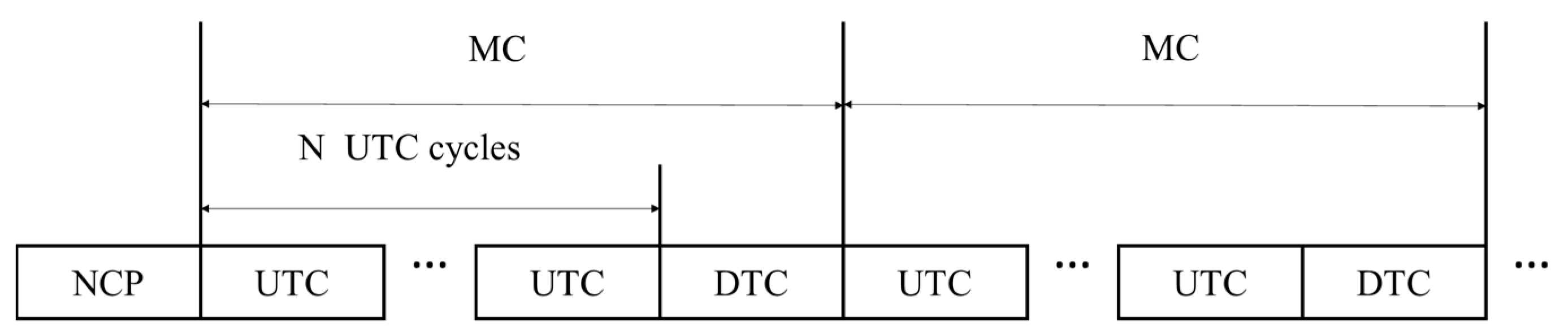
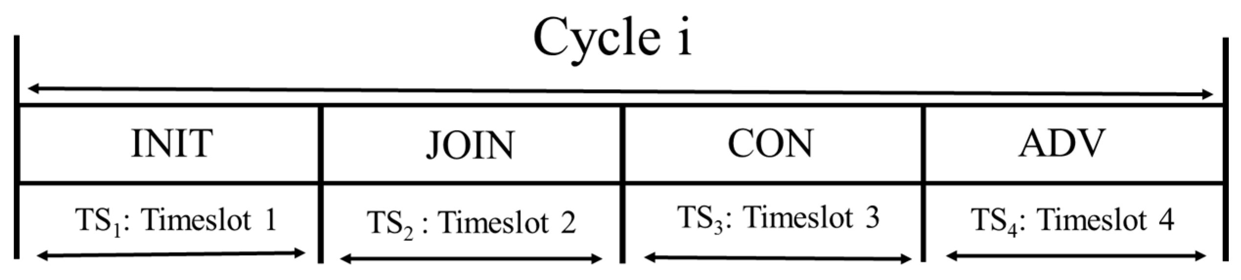
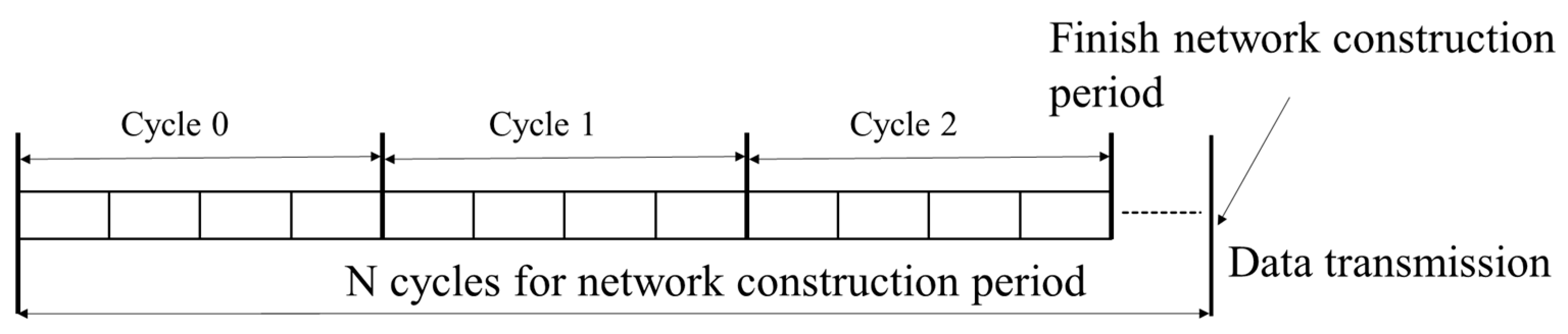
The proposed protocol consists of the network construction period (NCP), the upward transmission period (UTP) and the downward transmission period (DTP), as shown in Figure 1. In each cycle of the NCP, we have four timeslots, as shown in Figure 2. In NCP, it contains n cycles as shown in Figure 3.
3.1. Minimized Latency Multi-hop LoRa’s Key Aspects
The minimized latency Multi-hop LoRa protocol has some key features, which are described as follows:
- Distributed Aggregation Scheduling: all the nodes in the network make the schedule without all network topology information; they only know their neighbor nodes’ information.
- Parallel Transmissions: the proposed protocol allows parallel non-conflicting transmission in the network. This approach reduces the latency in the network and minimizes the number of timeslots that are assigned to all the links in the network.
- Minimize Packet Size: in the proposed protocol, based on the choice of parent, the packet sizes at the nodes will be minimized.
3.2. Network Construction Period
In the network construction period, the sink node first transmits INIT (D, SID, Cycle, N), where D is the depth of the sender node, SID is the node ID of the sender node, Cycle is the current cycle number (in which the sender node transmits the INIT packet), and N is the number of cycles in the NCP. Each node tries to receive an INIT packet from other nodes. After receiving an INIT packet, the node adds the sender node to the parent list and chooses the optimal parent from the parent list, as explained in the next sub-section, and then transmits a JOIN (D, SID, RID, UC) packet in TS2 of the current cycle. In the JOIN packet, SID and RID are node IDs of the sender and receiver, and UC is a cell assignment list (channels and timeslots) of its neighbors. UC is used by the receiver to choose a timeslot and a channel which is collision-free with its neighbors. In the NCP, each node collects UC information by overhearing JOIN, CON and ADV packets.
After transmitting the INIT packet, if a node receives a JOIN packet from a node, this node chooses a timeslot and a collision-free channel with the UC, as explained in the next sub-section, and then transmits a CON packet to the sender of the JOIN packet in the TS3 of the current cycle. The format of the CON packet is CON (D, SID, RID, Ts, Ch), where Ts and Ch indicate the assigned cell (timeslot, channel) for the receiver node to communicate with the sender node. Because all data from sensor nodes have to be forwarded to the sink node within one upward transmission cycle (UTC), we assumed TUTC = N × TS, in which TS is the length of one data timeslot. If the child node receives a CON packet from the parent node, it broadcasts an ADV packet, formatted as ADV (D, SID, RID, Ts, Ch), at timeslot TS4 to announce its cell assignment to its neighbor nodes.
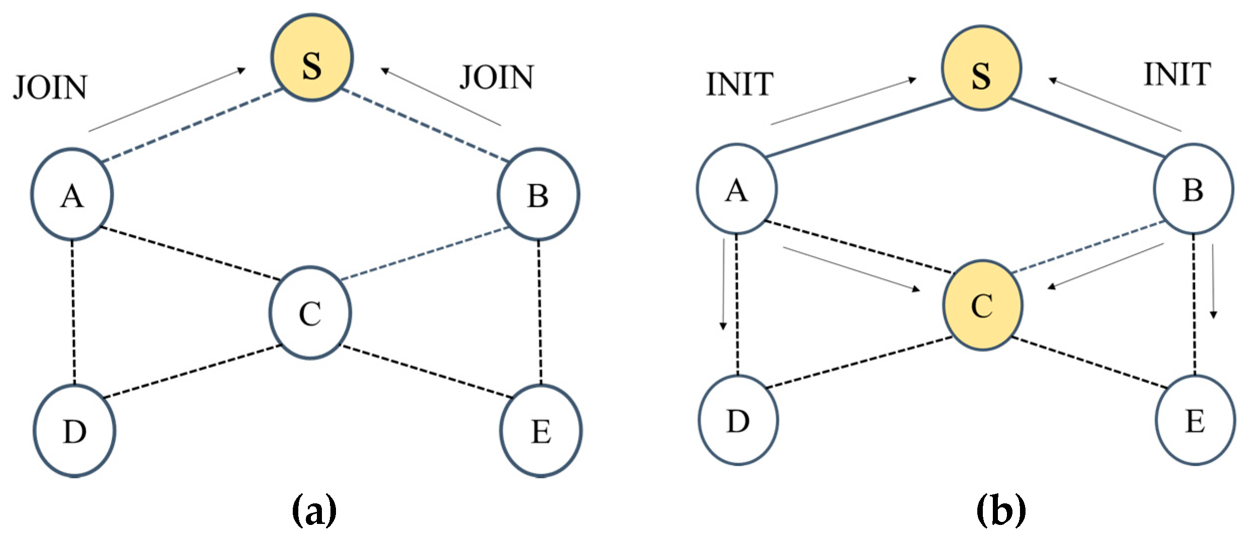
After receiving INIT, a node transmits the JOIN packet in TS2, but JOIN packets can collide, as shown in Figure 4a. We propose a packet collision–avoidance mechanism, as explained in the next sub-section, to avoid this. Collisions can happen between JOIN packets and INIT packets, as shown in Figure 4b. If a node loses contention, it tries to retransmit this packet in the next cycle.
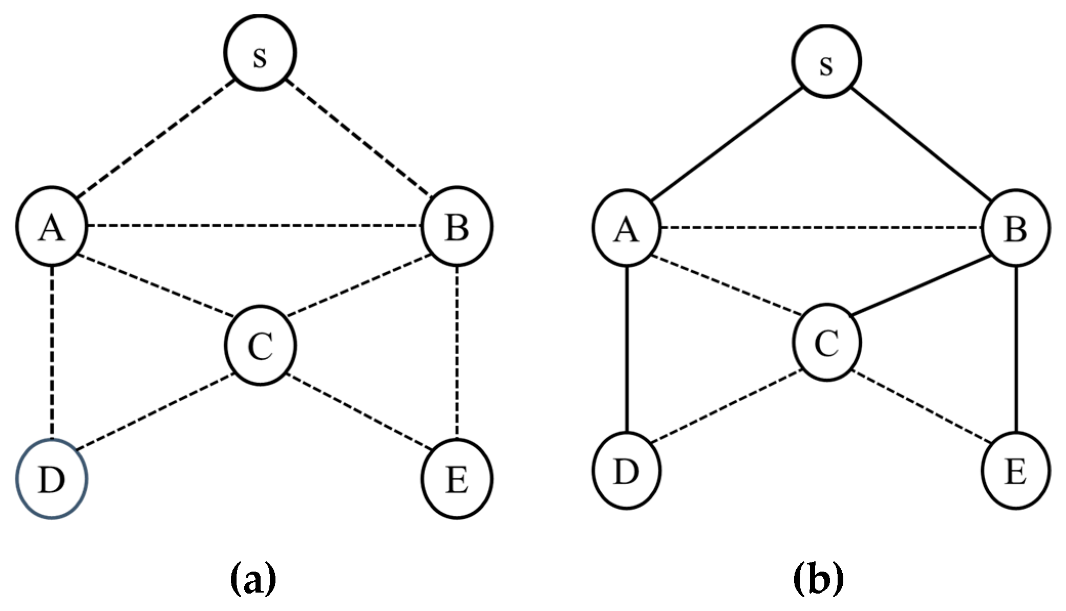
In the example in Figure 5, we demonstrate the NCP process with six nodes. At first, each node initializes its P, D, Cd and UC information, as shown in Table 1. We assume that TUTC = 5 × TS. First, the sink node transmits INIT(0,S,0,5) in timeslot TS1 in the first cycle (cycle 0). Nodes A and B receive the INIT packet from node S, and after that, nodes A and B compete to transmit a JOIN packet to node S. We assume node B wins, and node B transmits JOIN(1,B,S,{}). Node A determines it lost the competition and waits until TS2 (in the next cycle) to retransmit the JOIN packet. Node S receives the JOIN packet from node B and accepts node B as its child node. Based on UC and Cd, node S decides to assign timeslot T5 and channel Ch0 to node B to communicate with node S, as explained in the next sub-section. Node S transmits CON (0,S,B,T5,Ch0) to node B at TS3 to inform node B of its assignment. Nodes A and B receive the CON packet, B sets its parent as S and the cell assignment to P and UC, while node A adds (Ch0, T5) to its UC list. In TS4, node B broadcasts ADV (1,B,T5,Ch0) to inform its neighbor nodes of the cell assignment. After receiving the ADV packet, nodes A, C and D add (Ch0, T5) to their UC lists. In TS1 of the next cycle (Cycle 1), node B sends INIT (1,B,1,5), and nodes A, C and E receive this packet and add node B to their parent lists. In TS2, nodes A, C and D choose their parents as described in the next sub-section and compete to transmit a JOIN packet to the parent node. Node A wins then, sending JOIN (1,A,S,{(T5, Ch0)}) to node S. Nodes C and E determine that they lost the competition when overhearing the JOIN packet, and wait until TS3 (in the next cycle) to retransmit the JOIN packet. After receiving the JOIN packet from node A, node S accepts node A as its child and chooses TS4 and channel Ch0 as the link from A to S. Node S transmits CON (0,S,A,T4,Ch0) to node A at TS3 to inform node A of its assignment. Nodes C, B and D overhear this packet and add (Ch0, T4) to their UC lists. Node A receives this packet and sets its parent as S, adding the cell assignment to P. In TS4, node A broadcasts ADV(1,A,T4,Ch0) to inform the neighbor nodes about the cell assignment. This process is repeated until the network construction is completed. Figure 6 shows the NCP process, and Table 1 shows the information maintained by each node after the NCP finishes.
3.3. Packet Collision Avoidance Mechanism
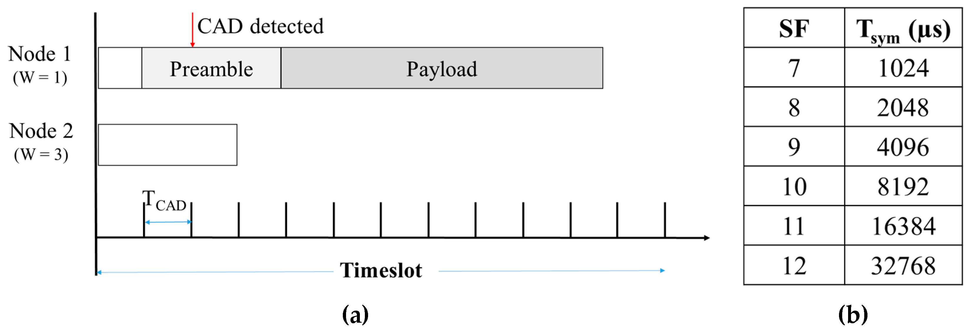
In LoRa, the transceiver uses the channel activity detection (CAD) mechanism to detect packets in the air [20]. We propose a packet collision avoidance mechanism based on CAD. In LoRa, we need TCAD (CAD time) to detect packets, and TCAD = 2 × Tsym, where Tsym is dependent on the spreading factor, as shown in Figure 7. In TS1 and TS2 of each cycle in the NCP, each node calculates a random delay time r (r = w × TCAD), where w = {D × CW, D × CW + CW−1}, in which D is the depth of this node and CW represents the contention window size, which checks the channel during this time and before transmitting a packet. During this, if the CAD mechanism detects a packet, it initiates a ‘CAD_detected’ event to inform the node that there is a packet in the air and that it lost contention and will have to try to retransmit the packet in the next cycle. Figure 7 shows an example when nodes 1 and 2 contend for the channel.
At Cycle 1 from the example in Figure 5, nodes A, E and C try to transmit a JOIN packet; some protocols use w = {0, CW−1}, and in this case, operations in NCP collision can occur for node B. The probability that no node can join the network in this cycle is ; however, when using the proposed mechanism, node A always joins the network. In this cycle, our mechanism increases performance in the NCP.
3.4. Timeslot and Channel Assignment
After overhearing the ADV, CON and JOIN packets from other nodes, UC is updated. Cd is updated when the timeslot and channel are already assigned to child nodes, and P is updated when a node receives a CON packet from the parent node. After receiving JOIN packet, at parent node, Algorithm 1 chooses the latest timeslot and channel that are collision-free with neighbor nodes before the timeslot in which this node communicates with its parent node to assign it to a child node of this node. This minimizes the number of timeslots that are used for assignments to all the links in the network. In the proposed protocol, we use data aggregation, and with this algorithm, all child nodes transmit a data packet to their parent node before the parent transmits the data packet. Thus, in one UTC, all data from LoRa nodes are forwarded to the sink node.
| Algorithm 1: Timeslot and channel assignment |
|
3.5. Parent Choice Mechanism
After a node receives the INIT, JOIN and ADV packets from the neighbor node, the node updates the information for Cd and UC. Before the node receives a timeslot and channel assignment from the parent node, this node updates its parent based on the parent choice mechanism from the parent list as a priority, which is Rule 1 (described below):
- The node has the lowest depth.
- The node has the smallest number of children.
- The node has the latest timeslot assigned for communication with its parent node.
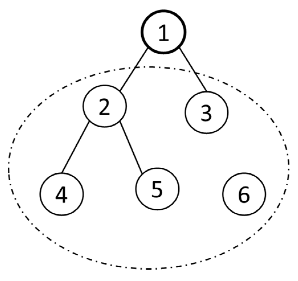
In Figure 8, node 6 can choose nodes 2, 3, 4 or 5 as a parent. Based on Rule 1, node 6 chooses node 3 as its parent node (node 3 has the lowest depth at 1, and the smallest number of children at 0). In this case, the end-to-end latency is lowest because node 6 will have a hop-count of 2. In data aggregation, because a minimized packet size is important, and the parent choice is important to minimize the packet size [14], we propose Rule 1 for choosing a parent to minimize packet size. In the example, we assume that every node has 60 bytes as the data size. If node 2 is chosen, it will have a 180-byte packet size, but if node 3 is chosen it will have 120 bytes as the packet size. To avoid exceeding the packet size, node 6 rejects node 2 as its parent to avoid exceeding the packet size. For that reason, node 6 chooses node 3, proving that Rule 1 will minimize the end-to-end latency as well as the packet size distribution.
3.6. Data Transmission in the Proposed Protocol
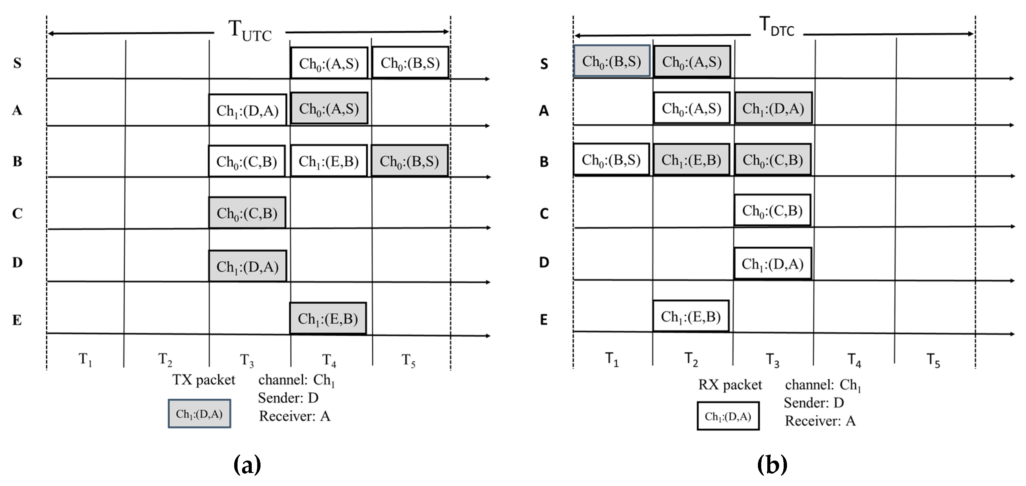
In each UTC, each node transmits one data packet. If the parent node receives all of the data packets from its child, it combines its own data, then transmits the packet using the channel and timeslot that is assigned during the NCP. An SX1272 LoRa transceiver has a maximum Rx buffer of 256B. To allow data aggregation, we restrict the degree (d) and depth (m) of the tree as follows: d × m ≤ ⌊256/L⌋, where L is the size of the data generated in each node. Figure 9a shows upward data transmission for each node in one UTC based on the example in Figure 5; before that, all of the nodes receive a REDUCE command packet from the sink node. After the UTCs of the proposed protocol, we have one downward transmission cycle (DTC) for the sink node to transmit a command packet to each node. For the downward data transmission, each node (including the sink) uses the same channel and timeslot in inverse order through the downlink of the tree. Figure 9b shows that the downward transmission of the command from the sink in the DTC of the proposed protocol before all the nodes receive the REDUCE command packet from the sink node.
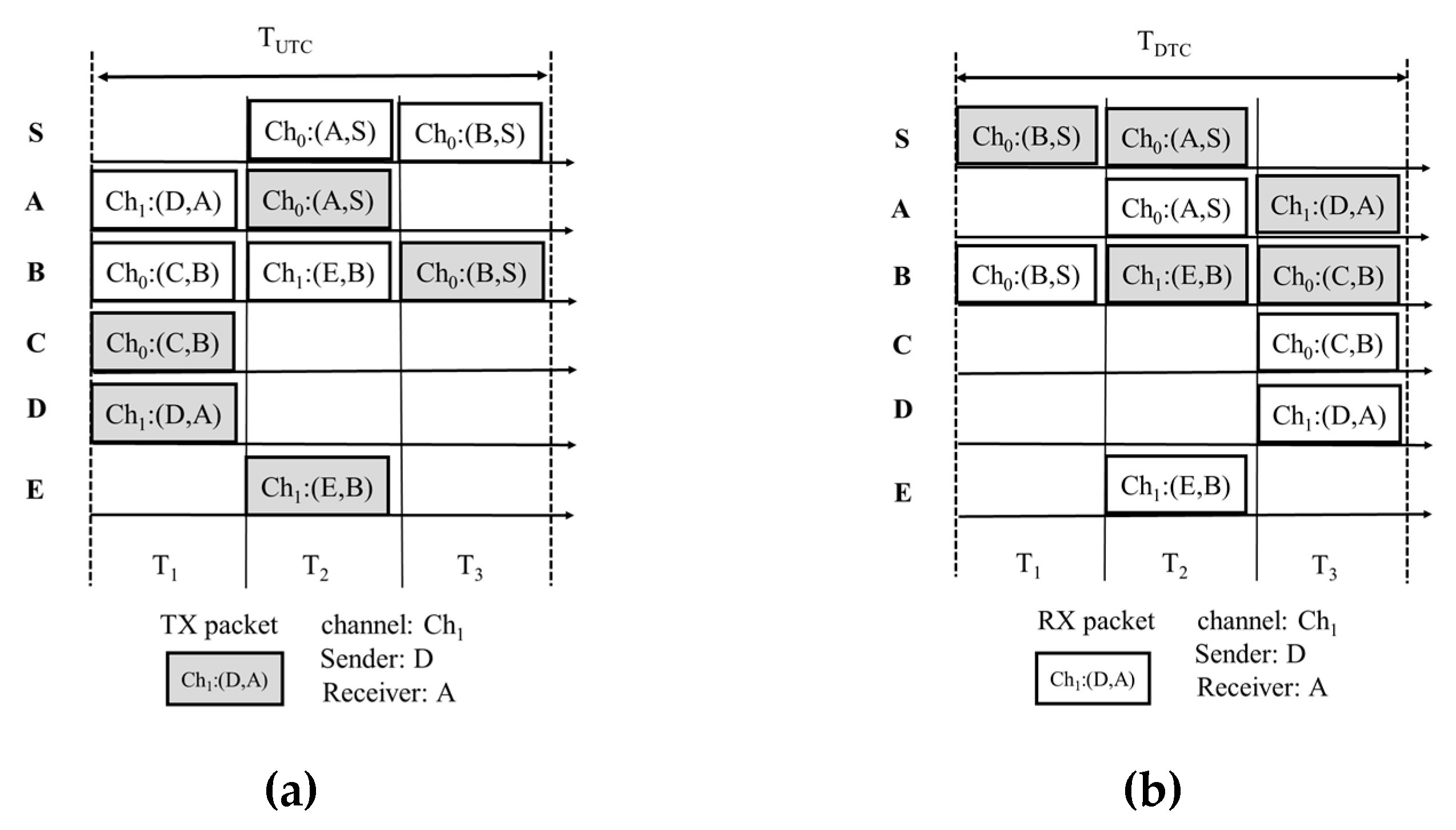
During the UTC in the data transmission period, the sink node collects timeslots assigned to all the nodes in the network, which are added to the data packet; based on this information, the sink node transmits the REDUCE command packet to all the nodes to reduce the number of timeslots in the slot-frame in the data transmission period. In Figure 9, we can see that two timeslots, T1 and T2, are not used; thus, to minimize the delay time and maximize the data rate, we removed these timeslots. Figure 10 shows data transmissions after all the nodes received the REDUCE command packet.
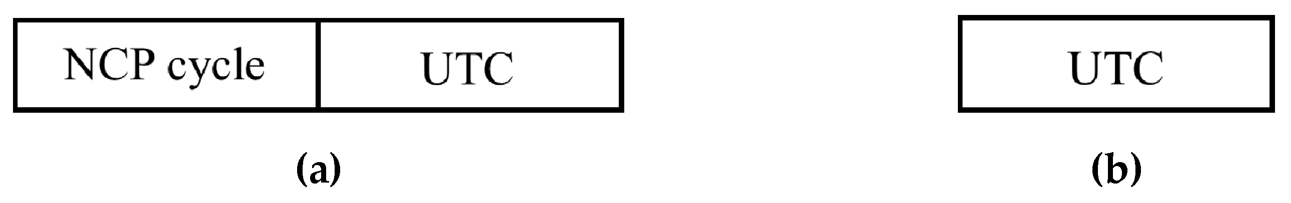
During the UTC in the data transmission period, all nodes forward a data packet to the sink node so that the sink node can know the number of nodes that joined the network. Based on this information, in the DTC, if the sink node determines that other nodes need to join the network, the sink node transmits the ADD command packet to notify all joined nodes to allow new nodes to join the network; thus in one UTC, we add one NCP cycle, as shown in Figure 11. After that, in the next DTC, if the sink node determines that all nodes have already joined the network, the sink node will transmit a REMOVE_ADD command packet to notify all of the nodes to remove the NCP cycle before the UTC, as shown in Figure 12.
3.7. Resynchronize Time Mechanism
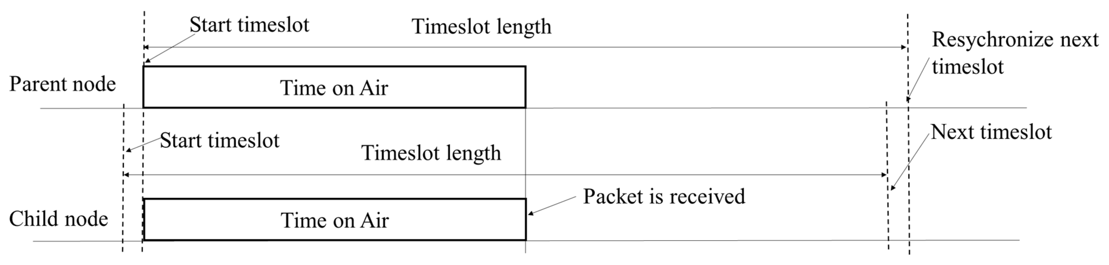
After receiving a command packet, based on Equation (1) [20], we calculated the time on air based on the received packet size, Spreading Factor (SF) and Coding Rate (CR); then, we estimated when the next timeslot starts, as shown in Figure 13, to resynchronize the time between the child nodes and the parent nodes.
- Time on Air:with the following dependencies:
- PL is the number of payload bytes
- SF is the spreading factor
- H = 0 when the header is enabled, and H = 1 when no header is present
- DE = 1 when low data rate optimization is enabled; DE = 0 when it is disabled
- CR is the coding rate from 1 to 4
- npreamble is the number of programmed preamble symbols
- Tsym =
This process repeats from the sink node to all leaf nodes, and all nodes in the network are resynchronized after finishing the DTC.
4. Experiment Evaluation
We developed the proposed protocol using the MultiTech mDot module [21], which consists of a Semtech SX1272 LoRa transceiver (Semtech, Camarillo, CA, USA) [20], and an STM32F411RET processor (STMicroelectronics, Geneva, Switzerland) based on Mbed OS, as shown in Figure 14. To evaluate the performance of the proposed protocol, we conducted an experiment by deploying 16 nodes with the set of parameters in Table 2.
We measured the performance from a successful tree construction of the proposed protocol in terms of contention window size, successful data reception ratio at the sink after tree construction and the end-to-end (E2E) delay average. The experiment was performed under the following scenario.
Scenario: nodes are deployed on the university campus area (400 m × 400 m) as shown in Figure 14, and the density of the nodes is 1 node/10,000 m2.
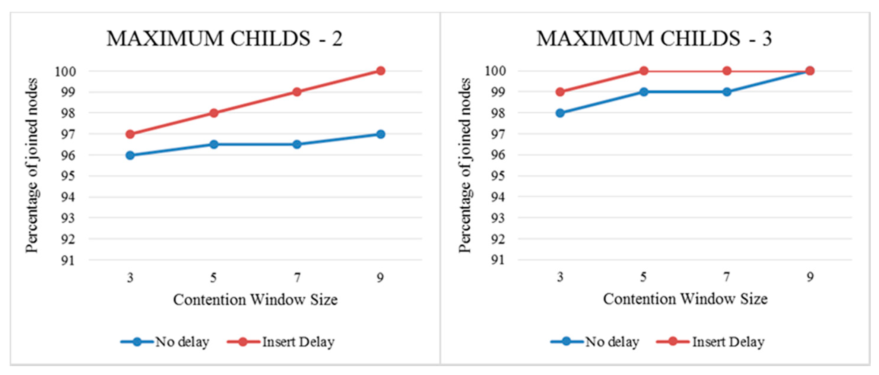
Figure 15 shows the percentages of joined nodes after the NCP for 16 nodes when we increase the contention window size, the percentages of joined nodes as the NCP increased. In no-delay mode, we only used the packet collision avoidance mechanism to avoid collisions when more nodes compete to transmit the INIT and JOIN packets; in insert-delay mode, we also applied the concurrent transmission (CT) LoRa effect [22], which increases the packet reception probability when more nodes compete to transmit the INIT or JOIN packets. This is the reason we used the insert-delay mode performance of the tree construction probability rather than the no-delay mode. In our protocol, when the data transmission period starts, if the sink node determines that some nodes did not join the network, the sink node will send the ADD command, as shown in Figure 12, which allows this node to join the network. This is the reason our protocol allows all the nodes to join the network. In this scenario, we measured data reception probability with 200 cycles during data transmission, and there was one DTC after 50 UTCs; thus, each node had 15B of sensor data to transmit. The result of the data reception probability is 97.6%. In this case, this value is higher than for the LoRaBlink [7] protocol.
Table 3 shows the number of timeslots used by all the nodes in the network for transmitting data packets during the data transmission period. The number of timeslots that the proposed protocol used is low because the proposed protocol allows parallel transmissions to minimize the number timeslots used by all nodes in the network; thus, the proposed protocol can increase the LoRa data rate. The result is better than the LoRa linear multi-hop protocol [8] because the LoRa linear multi-hop protocol needs the same number of timeslots as there are nodes in the network.
Table 4 shows the E2E delay average in the data transmission period. The proposed protocol has a low E2E delay average because it uses parallel transmissions; therefore, the proposed protocol can be applied to low-latency applications.
5. Conclusions
In this paper, we proposed a minimized latency multi-hop LoRa network protocol for IoT application, which aimed to achieve reliability and low latency when transmitting the data packet. In the proposed protocol, we applied the LoRa signal capture effect to increase the performance in tree-construction probability, used distributed aggregation scheduling to assign a timeslot and a channel to each link during the tree construction period. This protocol is more suitable for LoRa communication technology because the time we transmit a packet is much longer than with other technologies in WSNs. In the proposed protocol, each node can transmit data reliably by eliminating data packet collisions with neighbor nodes. We developed the proposed protocol using the Multi-tech mDot module, which consists of a Semtech SX1272 LoRa transceiver and an STM32F411RET processor in the Mbed OS platform. The experiments demonstrate that the proposed protocol has high data reliability and low latency. Our protocol is suitable for applications in agriculture and in tunnels. In agriculture, the application collects humidity, temperature and soil moisture from different vegetable gardens periodically to monitor each garden’s status at the central station. Based on this information, we took further actions to improve the crop yield with low-cost. In tunnels, the application collects carbon dioxide gas levels from different places periodically to monitor the carbon dioxide gas level status; based on this information, the application notified unsafe places in tunnels to employees who work in these tunnels. In future research, we will analyze the energy consumption of our protocol, and improve its performance in terms of energy consumption.
Author Contributions
Conceptualization, D.L.M. and M.K.K.; Methodology, D.L.M. and M.K.K.; Software, D.L.M.; Validation, M.K.K.; Formal Analysis, D.L.M.; Investigation, D.L.M.; Resources, M.K.K.; Data Curation, D.L.M.; Writing-Original Draft Preparation, D.L.M. and M.K.K.; Writing-Review & Editing, D.L.M.; Supervision, M.K.K.; Project Administration, M.K.K. All authors have read and agreed to the published version of the manuscript.
Funding
This research was supported by the Basic Science Research Program through the National Research Foundation of Korea (NRF) funded by the Ministry of Education, grant number KNRF-2017030208.
Conflicts of Interest
The authors declare no conflict of interest.
References
- Mekki, K.; Bajic, E.; Chaxel, F.; Meyer, F. A comparative study of LPWAN technologies for large-scale IoT deployment. ICT Express 2019, 5, 1–7. [Google Scholar] [CrossRef]
- LoRa. Available online: https://www.semtech.com/LoRa/what-is-LoRa (accessed on 2 March 2019).
- Zourmand, A.; Hing, A.L.K.; Hung, C.W.; AbdulRehman, M. Internet of Things (IoT) using LoRa technology. In Proceedings of the 2019 IEEE International Conference on Automatic Control and Intelligent Systems (I2CACIS), Shah Alam, Malaysia, 29 June 2019; pp. 324–330. [Google Scholar]
- Lavric, A. LoRa (Long-Range) High-Density Sensors for Internet of Things. J. Sens. 2019, 2019, 3502987. [Google Scholar] [CrossRef]
- Nguyen, T.T.; Oh, H. A receiver for resource-constrained wireless sensor devices to remove the effect of multipath fading. IEEE Trans. Ind. Electron. 2017, 65, 6009–6016. [Google Scholar] [CrossRef]
- LoRaWAN. Available online: https://LoRa-alliance.org/resource-hub/LoRawan-specification-v11 (accessed on 4 December 2018).
- Bor, M.; Vidler, J.E.; Roedig, U. Lora for the Internet of Things. In Proceedings of the 2016 International Conference on Embedded Wireless Systems and Networks (EWSN ’16), TU Graz, Styria, Austria, 15–17 February 2016; pp. 361–366. [Google Scholar]
- Duong, C.-T.; Kim, M.-K. Reliable Multi-Hop Linear Network Based on LoRa. Int. J. Control Autom. 2018, 11, 143–154. [Google Scholar] [CrossRef]
- Aijaz, A.; Raza, U. DeAMON: A decentralized adaptive multi-hop scheduling protocol for 6TiSCH wireless networks. IEEE Sens. J. 2017, 17, 6825–6836. [Google Scholar] [CrossRef]
- Soua, R.; Minet, P.; Livolant, E. DiSCA: A distributed scheduling for convergecast in multichannel wireless sensor networks. In Proceedings of the 2015 IFIP/IEEE International Symposium on Integrated Network Management (IM), Ottawa, ON, Canada, 11–15 May 2015; pp. 156–164. [Google Scholar]
- Darbandi, A.; Kim, M.K. Path Collision-aware Real-time Link Scheduling for TSCH Wireless Networks. KSII Trans. Internet Inf. Syst. 2019, 13, 4429–4445. [Google Scholar]
- Saifullah, A.; Xu, Y.; Lu, C.; Chen, Y. Real-Time Scheduling for WirelessHART Networks. In Proceedings of the 2010 31st IEEE Real-Time Systems Symposium, San Diego, CA, USA, 30 November–3 December 2010; pp. 150–159. [Google Scholar]
- Nguyen, T.T.; Oh, H. SCSMA: A Smart CSMA/CA Using Blind Learning for Wireless Sensor Networks. IEEE Trans. Ind. Electron. 2019. [Google Scholar] [CrossRef]
- Nguyen, T.T.; Oh, H. Constructing an optimally balanced tree to maximize data throughput with multiple channels. Wirel. Netw. 2018, 24, 993–1005. [Google Scholar] [CrossRef]
- Gao, Y.; Li, X.; Li, J.; Gao, Y. Distributed and Efficient Minimum-Latency Data Aggregation Scheduling for Multichannel Wireless Sensor Networks. IEEE Internet Things J. 2019, 6, 8482–8495. [Google Scholar] [CrossRef]
- Zhao, M.; Kumar, A.; Chong, P.H.J.; Lu, R. A reliable and energy-efficient opportunistic routing protocol for dense lossy networks. IEEE Wirel. Commun. Lett. 2016, 6, 26–29. [Google Scholar] [CrossRef]
- Lavric, A.; Petrariu, A.I.; Popa, V. Long range sigfox communication protocol scalability analysis under large-scale, high-density conditions. IEEE Access 2019, 7, 35816–35825. [Google Scholar] [CrossRef]
- Ikpehai, A.; Adebisi, B.; Rabie, K.M.; Anoh, K.; Ande, R.E.; Hammoudeh, M.; Gacanin, H.; Mbanaso, U.M. Low-power wide area network technologies for internet-of-things: A comparative review. IEEE Internet Things J. 2018, 6, 2225–2240. [Google Scholar] [CrossRef] [Green Version]
- Wu, W.; Li, Y.; Zhang, Y.; Wang, B.; Wang, W. Distributed Queueing Based Random Access Protocol for LoRa Networks. IEEE Internet Things J. 2019, 7, 763–772. [Google Scholar] [CrossRef]
- Semtech Transceiver SX1272 Datasheet. Available online: https://semtech.my.salesforce.com/sfc/p/#E0000000JelG/a/440000001NCE/v_VBhk1IolDgxwwnOpcS_vTFxPfSEPQbuneK3mWsXlU (accessed on 10 March 2020).
- MultiTech mDot Module. Available online: https://www.multitech.com/documents/publications/data-sheets/86002171.pdf (accessed on 10 March 2020).
- Liao, C.-H.; Zhu, G.; Kuwabara, D.; Suzuki, M.; Morikawa, H. Multi-hop LoRa networks enabled by concurrent transmission. IEEE Access 2017, 5, 21430–21446. [Google Scholar] [CrossRef]
Figure 1.
Structure of the minimized latency Multi-hop LoRa network.

Figure 2.
Four timeslots in each cycle in the network construction period of the minimized latency Multi-hop LoRa network.
Figure 2.
Four timeslots in each cycle in the network construction period of the minimized latency Multi-hop LoRa network.

Figure 3.
N cycles in the network construction period.

Figure 4.
Packet collisions during the NCP. (a) Collision between JOIN packets, (b) Collision between INIT packets.
Figure 4.
Packet collisions during the NCP. (a) Collision between JOIN packets, (b) Collision between INIT packets.

Figure 5.
An example network. (a) Network before NCP starts, (b) Network after NCP finishes.

Figure 6.
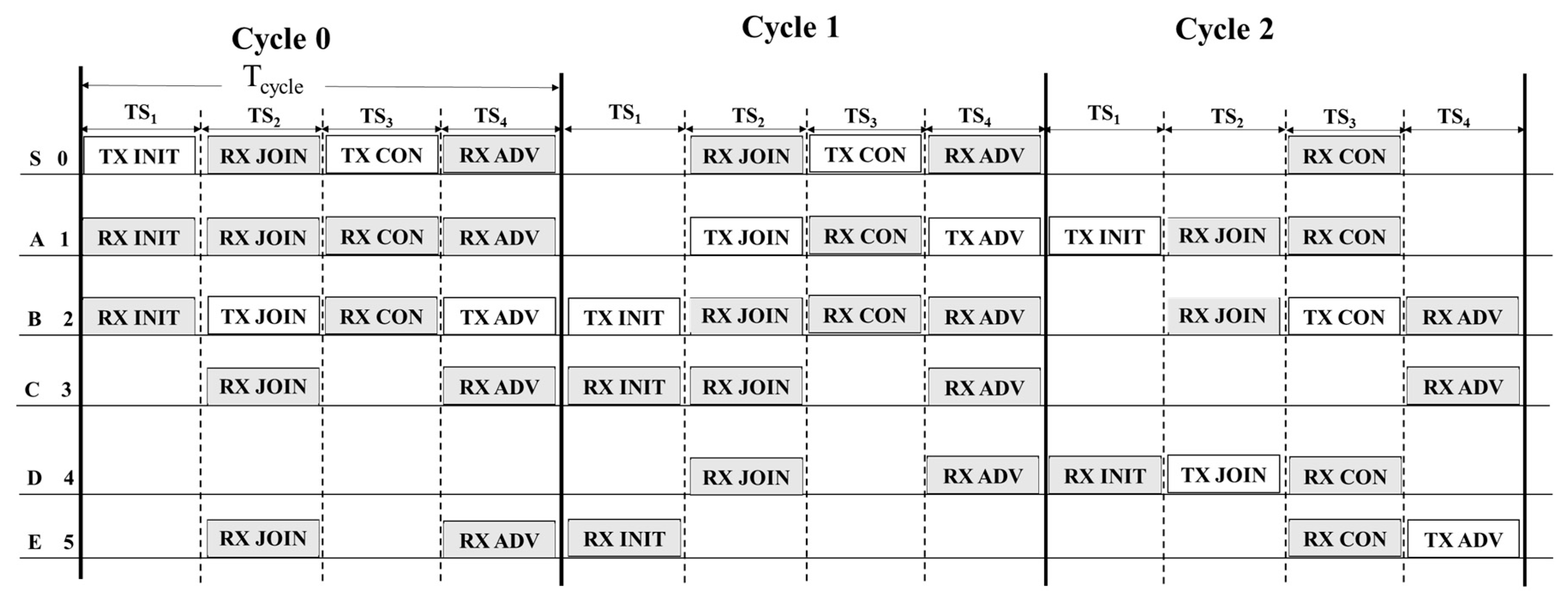
All the nodes’ operations in the NCP process for the example network in Figure 5.
Figure 6.
All the nodes’ operations in the NCP process for the example network in Figure 5.

Figure 7.
The collision avoidance mechanism. (a) Contention avoidance mechanism example with two nodes; (b) Symbol time (Tsym).
Figure 7.
The collision avoidance mechanism. (a) Contention avoidance mechanism example with two nodes; (b) Symbol time (Tsym).

Figure 8.
Parent choice example.

Figure 9.
Data transmission before receiving the REDUCE command packet. (a) Data transmission in the UTC; (b) Data transmission in the DTC.
Figure 9.
Data transmission before receiving the REDUCE command packet. (a) Data transmission in the UTC; (b) Data transmission in the DTC.

Figure 10.
Data transmission after receiving the REDUCE command packet. (a) Data transmission in UTC; (b) Data transmission in UTC.
Figure 10.
Data transmission after receiving the REDUCE command packet. (a) Data transmission in UTC; (b) Data transmission in UTC.

Figure 11.
Addition of an NCP cycle in the data transmission structure after receiving an ADD command from the Sink Node. (a) Before receiving ADD command packet; (b) After receiving ADD command packet.
Figure 11.
Addition of an NCP cycle in the data transmission structure after receiving an ADD command from the Sink Node. (a) Before receiving ADD command packet; (b) After receiving ADD command packet.

Figure 12.
Removing an NCP cycle from the data transmission structure after receiving the REMOVE_ADD command from the sink node. (a) Before receiving REMOVE_ADD command packet; (b) After receiving REMOVE_ADD command.
Figure 12.
Removing an NCP cycle from the data transmission structure after receiving the REMOVE_ADD command from the sink node. (a) Before receiving REMOVE_ADD command packet; (b) After receiving REMOVE_ADD command.

Figure 13.
Resynchronizing time between the child and parent nodes.

Figure 14.
Nodes deployment in the scenario. (a) Nodes deployed in the Scenario; (b) LoRa node prototype.
Figure 14.
Nodes deployment in the scenario. (a) Nodes deployed in the Scenario; (b) LoRa node prototype.

Figure 15.
Percentage of joined nodes during the NCP.


Table 1.
Information maintained by the nodes after the network construction period.
| Node | P | D | Cd | UC | ||||
|---|---|---|---|---|---|---|---|---|
| Before NCP | After NCP | Before NCP | After NCP | Before NCP | After NCP | Before NCP | After NCP | |
| S | NULL | NULL | 0 | 0 | Empty | (B, Ch0, T5), (A, Ch0, T4) | Empty | (Ch1, T4), (Ch0, T3), (Ch1, T3) |
| A | NULL | (S, Ch0, T4) | −1 | 1 | Empty | (D, Ch1, T3) | Empty | (Ch0, T5), (Ch1, T4), (Ch0, T3) |
| B | NULL | (S, Ch0, T5) | −1 | 1 | Empty | (C, Ch0, T3) (E, Ch1, T4) | Empty | (Ch0, T4), (Ch1, T3) |
| C | NULL | (B, Ch0, T3) | −1 | 2 | Empty | Empty | Empty | (Ch0, T5), (Ch0, T4), (Ch1, T4), (Ch1,T3) |
| D | NULL | (A, Ch1, T3) | −1 | 2 | Empty | Empty | Empty | (Ch0, T4), (Ch0, T3) |
| E | NULL | (B, Ch1, T4) | −1 | 2 | Empty | Empty | Empty | (Ch0, T5), (Ch0, T3) |
Table 2.
Experiment Configuration Parameters.
| Number of Deployed Nodes | 16 | Coding Rate (CR) | CR 4/5 |
| Bandwidth (BW) | 125 kHz | Preamble length | 8 symbols |
| Transmission Power | 0 dBm | Header mode | explicit |
| CRC | enable | Spreading factor | SF7 |
| Max Depth | 4 | Number of UTCs in the UTP | 50 |
Table 3.
The number of timeslots used in the experiment scenario.
| Number of Nodes | Maximum Children: 2 | Maximum Children: 3 |
|---|---|---|
| Number of used timeslots | Number of used timeslots | |
| 6 | 3 | 3 |
| 11 | 5 | 4 |
| 16 | 6 | 6 |
Table 4.
E2E delay average (timeslot).
| Number of Nodes | Maximum Children: 2 | Maximum Children: 3 |
|---|---|---|
| E2E delay average | E2E delay average | |
| 6 | 1.2 | 1.2 |
| 11 | 2 | 2.1 |
| 16 | 2.6 | 2.4 |
© 2020 by the authors. Licensee MDPI, Basel, Switzerland. This article is an open access article distributed under the terms and conditions of the Creative Commons Attribution (CC BY) license (http://creativecommons.org/licenses/by/4.0/).
Share and Cite
MDPI and ACS Style
Mai, D.L.; Kim, M.K. Multi-Hop LoRa Network Protocol with Minimized Latency. Energies 2020, 13, 1368. https://0-doi-org.brum.beds.ac.uk/10.3390/en13061368
AMA Style
Mai DL, Kim MK. Multi-Hop LoRa Network Protocol with Minimized Latency. Energies. 2020; 13(6):1368. https://0-doi-org.brum.beds.ac.uk/10.3390/en13061368
Chicago/Turabian StyleMai, Dinh Loc, and Myung Kyun Kim. 2020. "Multi-Hop LoRa Network Protocol with Minimized Latency" Energies 13, no. 6: 1368. https://0-doi-org.brum.beds.ac.uk/10.3390/en13061368
Note that from the first issue of 2016, this journal uses article numbers instead of page numbers. See further details here.