Dynamic Mechanical Compression Impulse of Lithium-Ion Pouch Cells


Warwick Manufacturing Group (WMG), University of Warwick, Coventry CV4 7AL, UK
*
Author to whom correspondence should be addressed.
Energies 2020, 13(8), 2105; https://0-doi-org.brum.beds.ac.uk/10.3390/en13082105
Submission received: 24 February 2020
/
Revised: 17 April 2020
/
Accepted: 17 April 2020
/
Published: 23 April 2020
(This article belongs to the Section D1: Advanced Energy Materials)
Abstract
:Strain rate sensitivity has been widely recognized as a significant feature of the dynamic mechanical properties of lithium-ion cells, which are important for their accurate representation in automotive crash simulations. This research sought to improve the precision with which dynamic mechanical properties can be determined from drop tower impact testing through the use of a diaphragm to minimize transient shock loads and to constrain off-axis motion of the indenter, specialized impact absorbers to reduce noise, and observation of displacement with a high speed camera. Inert pouch cells showed strain rate sensitivity in an increased stiffness during impact tests that was consistent with the poromechanical interaction of the porous structure of the jellyroll with the liquid electrolyte. The impact behaviour of the inert pouch cells was similar to that of an Expanded Polypropylene foam (EPP), with the exception that the inert pouch cells did not show hysteretic recovery under the weight of the indenter. This suggests that the dynamic mechanical behaviour of the inert pouch cells is analogous to a highly damped foam.
1. Introduction
At the time of writing, cost effective finite element modelling of vehicle impact in the absence of a supercomputer is typically limited to several millions of elements [1,2]. For full vehicle crash simulations, it may therefore only be computationally efficient to represent individual lithium-ion cells with several thousands of elements, which is insufficient to model all of the layers of the jellyroll [3]. Therefore, simulation of the mechanical behaviour of lithium-ion cells has frequently involved techniques for homogenizing the internal micromechanics to give macroscopic material properties. Homogenization techniques have included representative volume elements [4,5,6], material models validated with empirically derived engineering constants [7] and estimation of globalized properties from individual layers [8]. These ‘macroscopic’ approaches contrast with ‘microscopic’ or ‘detailed’ modelling, which seeks to represent individual layers in the jellyroll as separate entities [9].
In a review of mechanical modelling of lithium-ion batteries, Zhu identified aspects of mechanical behaviour inherent to lithium-ion cells that should be represented by accurate homogenized material models that included [10]: the pressure dependence of the compression stiffness of porous layers, the poromechanics of the electrolyte-filled porous structure of the jellyroll, anisotropy of individual layers, plasticity, and crack propagation. Despite the complexity of multi-physics in the jellyroll [11,12,13], a notable consensus has arisen within a growing body of research that structural properties can be adequately approximated in solid mechanical terms for the practical finite element simulation of lithium-ion cells [6,14,15,16,17,18,19]. Due to the common motivation of simulating automotive crash events, research has been predominantly concerned with bending and compression deformation. The through-thickness compression of jellyrolls has been observed to occur with a negligible in-plane Poisson’s ratio [20] and has been likened to the behaviour of cellular materials [21]. To this purpose, crushable foam and honeycomb material models have been frequently employed for homogenization techniques in commercial finite element codes such as LS DYNA and Abaqus [4,15,18,21,22,23,24,25,26,27,28,29,30,31,32,33,34,35,36]. The stiffness of polymeric foams is strain-rate dependent and is generally characterized by three phases of compression [37,38,39,40]. This begins with a linear elastic region and once a yield strain has been reached, the foam experiences a ‘plateau’ region of relatively constant stress that corresponds to the majority of energy absorption of a cellular material under compression. Further compression results in densification, in which the stiffness of the collapsed matrix behaves in a similar manner to a dense bulk material [41,42,43]. Elastic foams may be repeatedly deformed within a prescribed range of motion without apparent loss of stiffness, which lends them to applications requiring both high energy absorption and long service life, such as automotive interiors [44,45].
Given the application of finite element modelling to vehicle impact analysis, a significant area of study is the strain rate dependence of the jellyroll. Xu and Kisters showed that cylindrical and prismatic cells respond with increased stiffness and greater peak load when compressed, flexed, and indented at higher strain rates, and they characterized this behaviour with a principle of strain hardening [7,46]. Kisters observed higher peak loads in ‘dry’ elliptical cells without the presence of an electrolyte and deduced that the strain rate dependence of wet cells was influenced by the poromechanics of fluid pressure within the porous structure of active electrode material and separator layers. This is consistent with Gilaki’s observation of higher peak loads in dry jellyroll stacks [35]. Dixon confirmed that dry cells experience comparatively higher peak loads under indentation and explained that this is due to the softening effect of the liquid electrolyte on cell layers in wet cells, a finding that was latterly supported by Chen [47,48]. Furthermore, Jia observed that the hardening effect of strain rate dependence has a greater influence on the magnitude of compression stress than the dependence of compression stiffness on the state of charge, which is known to arise from volumetric changes in graphite and silicone anodes due to the intercalation of lithium ions [49]. Intercalation stresses during electrical cycling causes swelling of the jellyroll, although this form of electrochemically-driven reversible expansion and contraction occurs at a much lower strain rate than that of impact events [50]. Through simulation of fluid flow of the electrolyte within the porous structure of the jellyroll, Zhu demonstrated that the poromechanics that governs the strain rate dependence of individual layers is also manifest in the macroscopic behaviour of jellyroll stacks [51]. Kalnaus found that as the testing speed of through-thickness compression of pouch cells was increased, load-displacement plots changed in shape from concave parabolic curves that resembled the compaction of cellular materials to convex curves that were characteristic of the compression of dense materials [52].
Investigations of compression and indentation of lithium-ion cells at quasi-static test speeds have been undertaken with universal test frames. Inertial phenomena can be effectively ignored at low test speeds [53,54,55,56,57] but are significant at higher test speeds [58]. A consequence of this is that testing at intermediate speeds is affected by the propagation of stress waves that contribute to vibration noise, especially in the measurement of transient loads [59]. This is particularly notable for falling mass test devices that can achieve high impact energies but unlike universal test frames are typically unable to actively maintain a constant strain rate due to deceleration of the indenter [60,61]. Due to their general availability and ubiquity, drop towers have been used in a number of studies concerning the dynamic mechanical properties of lithium-ion cells [34,48,49,62]. This investigation considered adaptations to falling mass impact methodologies with the aim of improving the precision with which dynamic mechanical properties of lithium-ion cells can be determined from drop tower experiments. This included the use of a diaphragm to reduce transient shock loads on the sample and to constrain the off-axis motion of the falling mass, specialized impact absorbers for achieving stable rates of deceleration, and a high-speed camera for observing displacement.
2. Experimental
2.1. Materials
Materials included Expanded Polypropylene (EPP) Arpro 5130, a carbon black-filled EPP with a mean bulk density of 30 kgm−3 and inert pouch cells manufactured at the Battery Scale-Up Line at the Energy Innovation Centre, Warwick Manufacturing Group, as summarized in Table 1. Inert pouch cells were utilized in this investigation due to safety restrictions on the testing of live lithium-ion cells in the workshop where the drop tower is located. The foam was originally acquired in a single 1200 × 800 × 200 mm block and then cut into smaller pieces using a band saw, following the methodology for sample preparation reported by Carnegie [63]. Inert pouch cells contained 14 repeating units of an iron phosphate (FePO4) double-layer cathode, a tri-layer separator and a graphite double-layer anode that after stacking were filled with a pure dimethyl carbonate (DMC) electrolyte and sealed in a pouch without a subsequent formation cycle, owing to the inertness of the electrolyte that lacked any lithium salt content. The electrodes were cut to a length and width of 70 × 35 mm and the mean thickness of the inert pouch cells was 4.5 mm.
2.2. Quasi-Static Compression
Quasi-static compression tests were undertaken on five inert pouch cells using a Zwick AllroundLine 250 kN test frame with flat compression platens. A test speed of 1 mm/min was used for all compression tests, which were terminated when the load reached a maximum safety limit of 245 kN.
2.3. Compression Impulse with Diaphragm Method Development
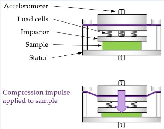
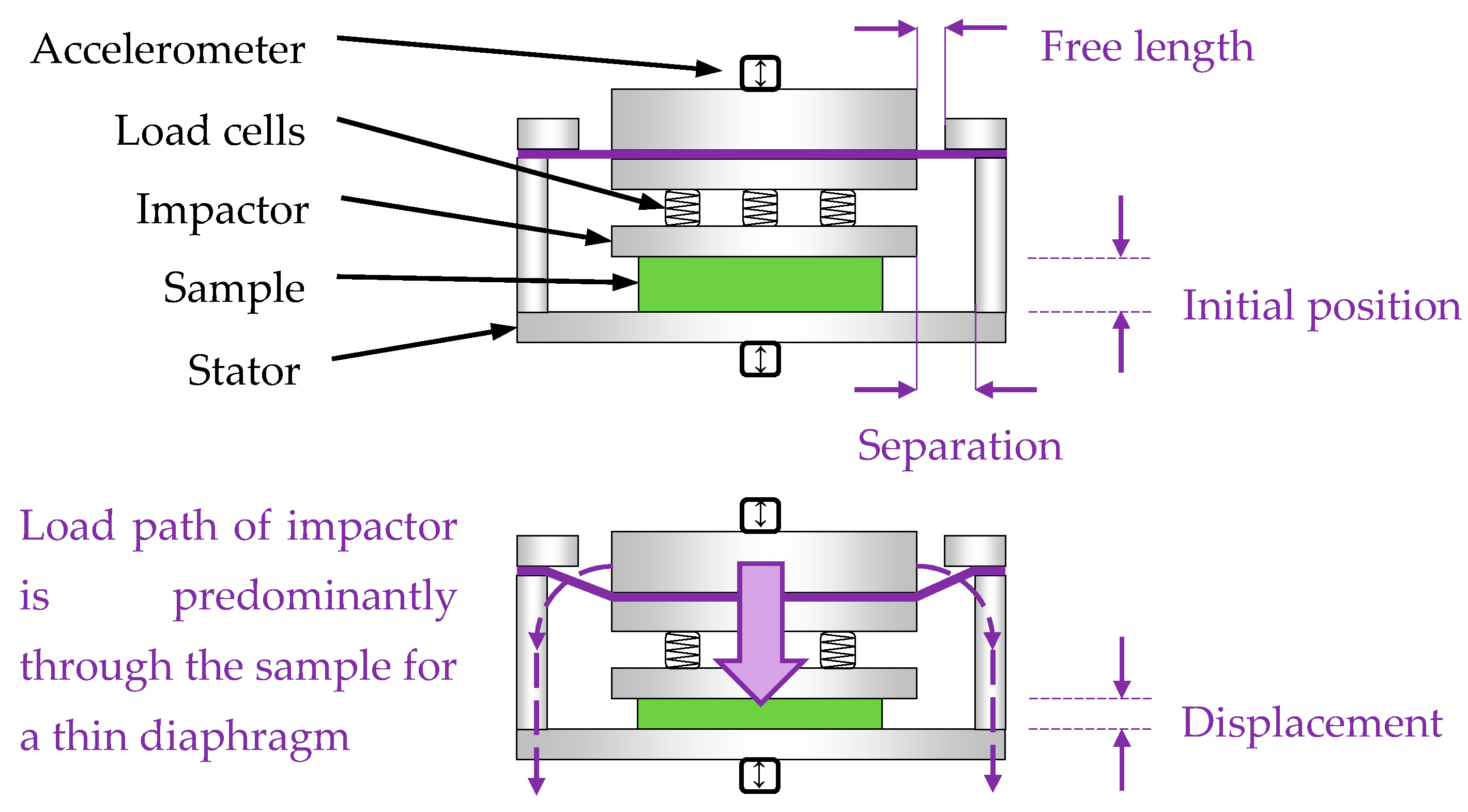
Drop towers typically apply a falling indenter directly onto the sample, resulting in transient shock loads at the point of impact. Unless tolerances of flatness and parallelism can be controlled to a high precision, variation in the area of impact and unpredictability of contact phenomena such as chattering may introduce noise to the load signal. Capturing transient shock loads at high strain rates therefore constitutes an instrumentation challenge that is not typically encountered in the measurement of quasi-static elastic mechanical properties, such as Young’s modulus. In an effort to reduce noise from hard contact with an indenter, a fixture was designed that utilized a diaphragm to constrain the position of samples so that they were in contact with compression platens throughout the whole duration of an experiment. Samples were thus sandwiched between a lower ‘stator’ platen that was fixed to the falling carriage of the drop tower and an upper ‘impactor’ platen that acted as a flat indenter. During an experiment, movement of the impactor relative to the stator applied a compression impulse through the sample, as shown in Figure 1. The diaphragm permitted vertical translations for small deflections and prevented the sample from being ejected by the reaction force exerted by the sample and constrained horizontal and planar rotations relative to the flat upper surface of the sample. A limitation of the diaphragm is that it represented a load path for the reaction force from the impactor to be transmitted directly to the stator rather than through the sample. Several design features were introduced to minimize the influence of the load path through the diaphragm: the diaphragm was fabricated from a CS75 spring steel sheet with a minimal thickness of 0.5 mm, a ‘free length’ of 30 mm between the impactor and supporting wall of the stator minimized stress concentration close to the edges of the impactor, and the ‘separation’ between the impactor and the supporting wall was limited to 1 mm by a cap that constrained the diaphragm from upward travel after compression impulses in order to dampen ringing modes. Rubber pads have been shown to minimize the bias introduced by ringing in drop tower impact experiments [64], so Fabreeka Fabcel 300 rubber pads were placed between the stator and the carriage such that there would be no points of steel-to-steel contact between the stator and its fasteners with the carriage.
A feature of impact tests with falling mass devices is non-constant test speed due to variable deceleration. Researchers have addressed this either by averaging the test speed for the whole period of compression [38,57] or by using bespoke testing methods to achieve control of test speed during tests. For instance, Bouix and Viot utilized a flywheel-driven impactor for testing foams [61,65] that was originally developed to generate a near-constant test speed by Froustey [66]. This investigation considered an alternative method, in which control of deceleration was achieved by utilizing an impact absorber with mechanical properties that were optimized in order to achieve an approximately constant rate of deceleration. This may be achieved by cellular materials, such as pre-crushed honeycombs and brittle foams in the plateau region of compression. Owing to limitations of laboratory space, a suitable alternative was found in die expansion of thin-walled tubes, which was investigated by Moreno for the purpose of impact absorption for railway vehicles [67]. The technique involves penetration of a seamless tube by a circular die that has a circumference slightly larger than that of the tube. As the die travels into the tube, it expands the circumference of the tube at an approximately constant rate. Like other related thin-walled tube techniques such as inversion and splitting, this technique has been valued for generating an approximately constant deceleration and high efficiency in energy absorption [68]. Seamless hydraulic tubes were chosen for this role due to their approximately constant wall thickness and diameter and the relatively low cost of individual specimens.
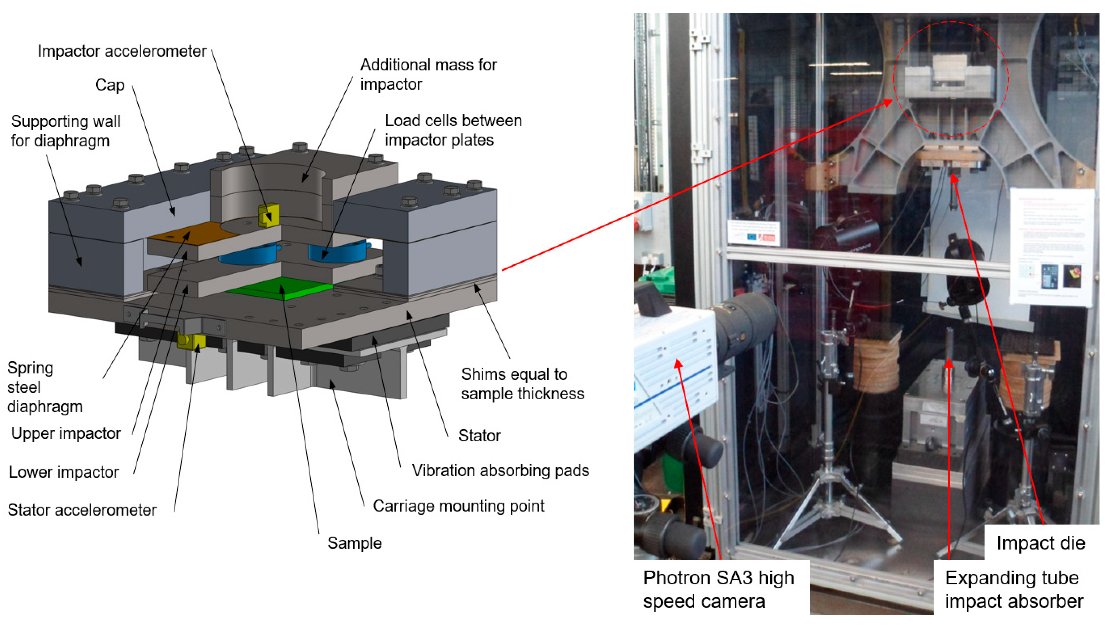
The impactor consisted of two opposing aluminium plates that were instrumented with three low-profile Kistler 4576A 5 kN strain gauge load cells with amplification from a VPG 2310 signal conditioner for the purpose of directly measuring the reaction force of the impactor against the sample. In addition, StrainSense 4604 MEMS DC amplified accelerometers were attached to the impactor and stator in order to quantify acceleration, with excitation voltage supplied by a TENMA bench top power supply. Displacement was measured by direct visual observation of the relative distance between the impactor and the stator by image correlation with a Photron SA3 high speed camera at a frame rate of 15,000 frames per second using Photron FASTCAM Analysis (PFA) software. Voltage outputs for the load cells and accelerometers were captured by Photron FASTCAM Viewer (PFV) with a National Instruments DAQ USB-6251 that was triggered at the start of each impact test by a digital edge from the high-speed camera. Additional lighting was provided by two Simpact ICARUS LED lights. A summary of experimental apparatus is shown in Figure 2.
2.4. Compression Impulse Methodology
Dynamic compression impulse tests were undertaken on 1 EPP foam sample and 5 inert pouch cells using the fixture and test apparatus described in Section 2.3. Specially manufactured flat plate shims with a thickness equal to that of the samples were used to ensure that the impactor would be resting under its weight on top of the sample at the start of the test. Additional steel plates were attached to the impactor to increase the mass of the fixture. The total mass of the impactor, diaphragm, instrumentation, and mass plates above the sample, collectively known as the ‘indenter’ was 14.9 kg, as measured by a digital balance. Each sample was repeatedly tested in a series of 8 impact events, with a period of approximately 5 min between each impact to allow for the previously crushed tube to be replaced with a new tube and to raise the carriage to its impact height. Samples were only removed from the fixture once the whole series of 8 tests had been completed. The speed of the carriage at the point of impact was 2.9 ms−1 for all tests. The impact energy for all tests was 600 J, which refers to the kinetic energy of the falling mass that was absorbed by the impact absorber and the sample during an impact event. The graphs shown for compression impulse tests in Section 3 include the mean values from all the impact tests for each material, therefore representing the mean of 8 tests for the Arpro 5130 EPP foam sample and 40 tests for the five inert pouch cells. The colour-shaded regions in the graphs represent one standard deviation from the mean.
As explained in Section 2.3, the diaphragm represents a parasitic load path by which load can be transferred through tension to the sides of the fixture and therefore directly to the stator rather than the sample. The magnitude of the parasitic tension that is lost through this load path was estimated from beam deflection equations [69], assuming that the diaphragm acted as a thin sheet that was constrained by the fixed walls of the fixture.
3. Results and Discussion
3.1. Arpro 5130 EPP Foam
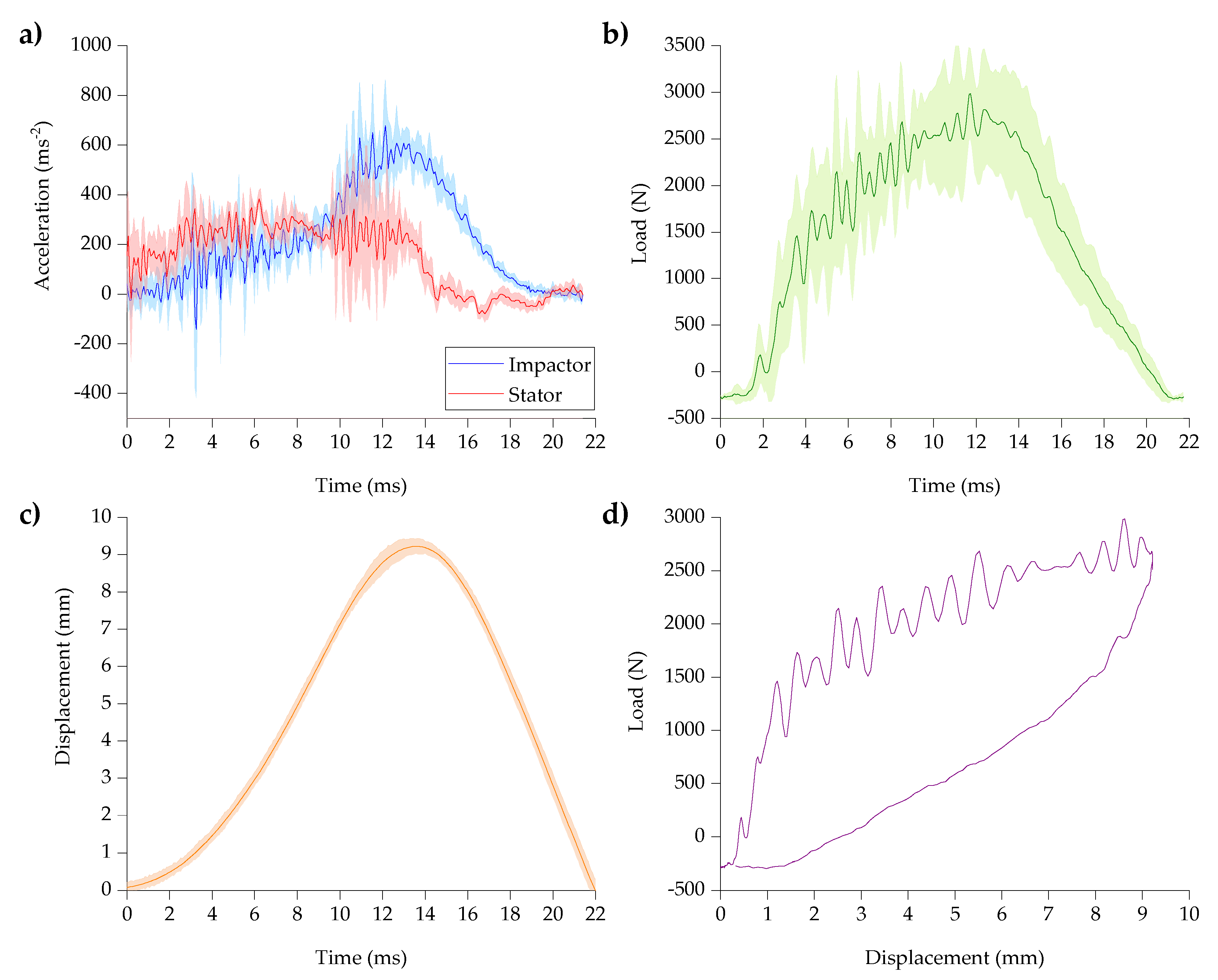
As shown in the acceleration traces in Figure 3a, the duration of the impact event for Arpro 5130 was approximately 20 ms. The stator reached a peak acceleration after approximately 3 ms, while the peak acceleration of the impactor lagged behind the stator. The intervening period of approximately 10 ms between the peak acceleration of the stator and impactor represents the ‘impulse’ portion of the impact, in which the difference in momentum between the impactor and stator produced a compression impulse on the foam sample. This is evident from the load trace shown in Figure 3b, which demonstrates approximately bilinear behaviour; the load rises steeply at the start of the compression impulse until the gradient of the curve decreases at approximately 4 ms, after which the load rises at an approximately constant rate until it decreases at approximately 14 ms. The rubber pads and impact absorber were successful in removing much of the high frequency noise but a low frequency ringing mode is evident throughout the curve in Figure 3b, which may have been caused by off-axis movement of the drop tower carriage during its descent. The magnitude of the fluctuations in the load that were caused by sinusoidal noise were maximal during the impact event and were gradually damped by the impact absorber. The efficacy of the impact absorber in creating a near-constant rate of compression is demonstrated by the approximately linear rate of change of displacement during the impulse period, as shown in Figure 3c.
Repeatability in the mean of the acceleration, load, and displacement suggests that there was no significant plastic deformation of the foam between tests. Consequently, the resultant force-displacement curve shown in Figure 3d resembles the expected elastic hysteresis behaviour of cyclic loading and unloading of a cellular material under compression. The approximately bilinear behaviour is representative of the elastic and compaction regions of compression. For a sample thickness of 50 mm, the peak displacement of 9 mm represents a compression strain of 18%. This is well below the threshold for plastic densification of Arpro 5130 that was observed by Carnegie to occur above 50% compression strain [63].
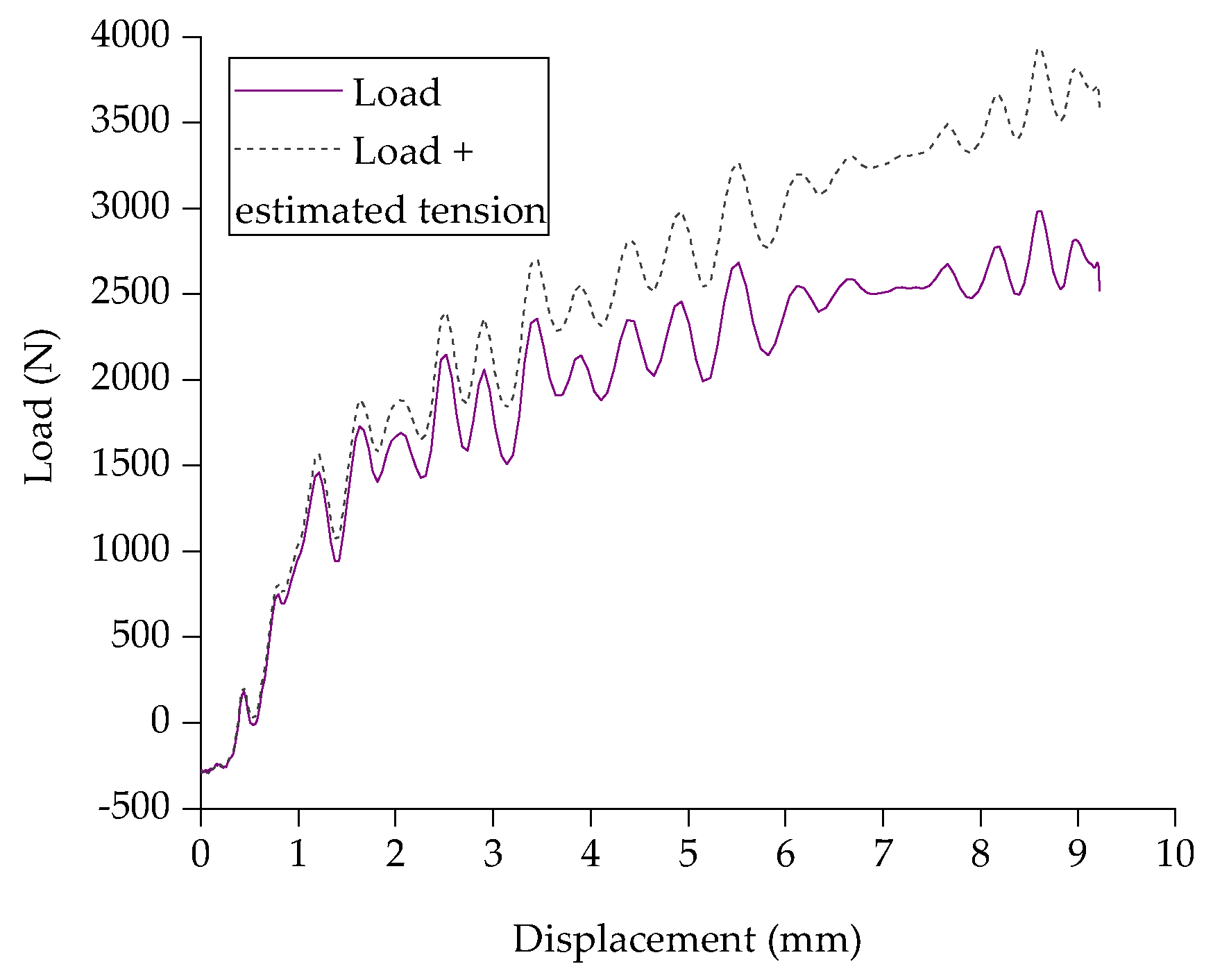
The measured load of the compression impulse is compared with the sum of the measured load and the estimated tension in the diaphragm in Figure 4. The estimated tension is proportional to the deflection of the diaphragm and is therefore maximal at the greatest deflection, which approximately coincides with the peak load. The peak tension at a displacement of 9 mm has an estimated value of approximately 1040 N, compared with a peak measured load of 2526 N. At almost 40% of the peak load, the tension in the diaphragm represents a considerable load path to the stator and constitutes a significant bias to the test. Nonetheless, the tension is relatively low at the small displacements of up to 1 mm for which the test method was intended. This suggests that the test method may be less suitable for testing substances with large ranges of deformation, such as foam blocks, but adequate for smaller ranges of displacement, such as those encountered with pouch cells.
3.2. Inert Pouch Cells
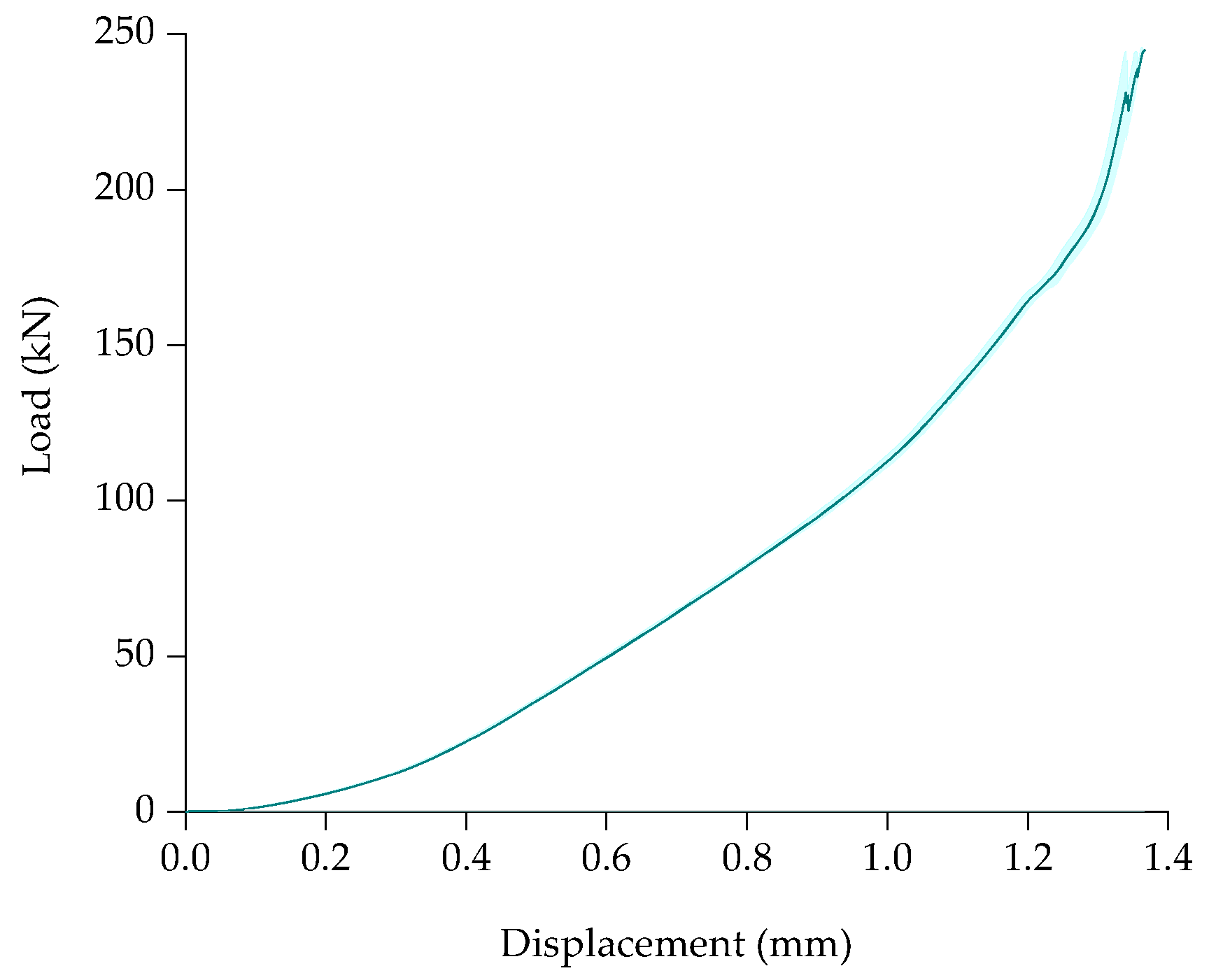
The concave shapes of the force-displacement curves for quasi-static compression of inert pouch cells shown in Figure 5 resemble the compaction behaviour of a porous material under compression, as described by Kalnaus [52]. This diverges from the expected compression behaviour of an elastomeric foam insofar as the compaction region is characterized by a relatively steep monotonic increase in load rather than a plateau. At loads above approximately 190 kN, the inert pouch cells experienced a rapid increase in stiffness that is analogous to the densification region of a cellular material and this can be interpreted as the maximal densification of the porous structures of the jellyroll layers.
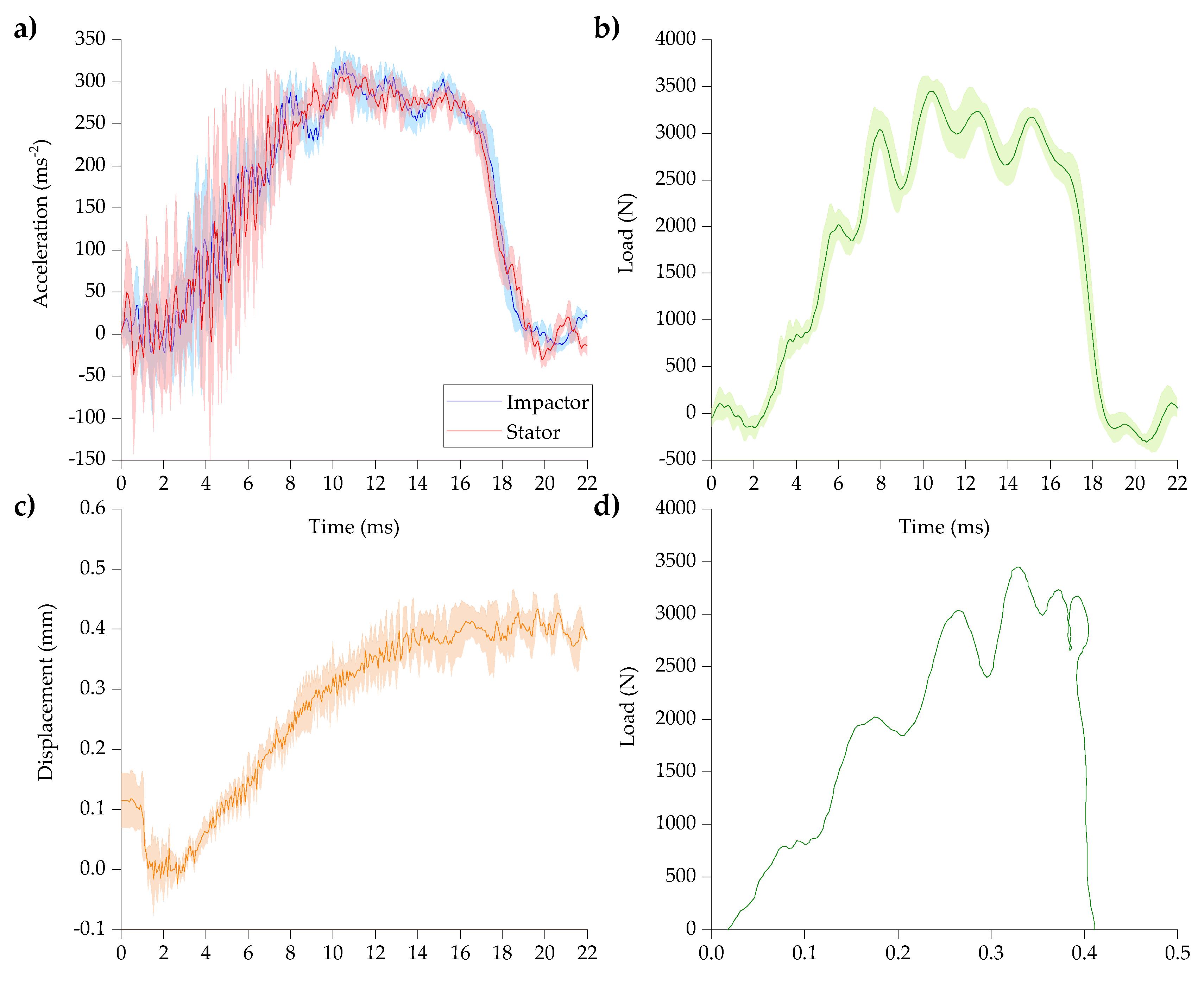
Unlike the acceleration traces of Arpro 5130 foam, the acceleration response of the impactor and stator for the inert pouch cells shown in Figure 6a closely resemble one another in shape and magnitude. This can be explained by the lower thickness and greater through-thickness stiffness of the inert pouch cells, which permitted greater rigidity in load transfer between the stator and impactor. The load trace for the inert pouch cells shown in Figure 6b resembles the first portion of the load trace for Arpro 5130 shown in Figure 3b in its trend of approximately linear elasticity followed by a plateau. The displacement trace for inert pouch cells in Figure 6c shows a similar trend to that observed for Arpro 5130 in Figure 3c with an approximately constant rate of change of displacement before reaching a peak. In contrast with the concave shape of the force-displacement curves at quasi-static test speeds, force-displacement curves for compression impulse were convex, which matches the finding of a strain rate dependent increase in stiffness that was observed by Kalnaus [52]. Given the similarity in the convex shape of the curves, this suggests that the strain rate sensitivity in inert pouch cells arises from the same poromechanical phenomenon that has been observed for live pouch cells [46,51].
The estimated tension in the diaphragm at the observed peak displacement of 0.42 mm in Figure 6b is approximately 60 N. This is approximately 2% of the load at peak displacement observed in the force-displacement curve for the pouch cells shown in Figure 6d and therefore this represents a much smaller bias to the load path into the sample than that noted for the Arpro 5130 foam sample in Figure 4. A notable difference between the inert pouch cells and the Arpro 5130 foam sample is that the displacement of the foam rapidly fell to zero after reaching a peak in Figure 6c, whereas the displacement of the inert pouch cells reached a plateau in Figure 6c. Thus, the force-displacement curve for the inert pouch cells does not feature a hysteresis loop for unloading. Repeatability of the displacement and force curves in Figure 6b,c shows that the inert pouch cells relaxed between tests; had this not been the case, the repeated trend of a linear increase in displacement and force followed by a plateau would not have been observed. This could only have occurred when the impactor and stator were in free-fall at the start of each successive impact test, which implies that while the jellyrolls of the inert pouch cells were capable of elastic recovery, this could not occur under the 14.9 kg weight of the indenter. Therefore, both Arpro 5130 and the inert pouch cells showed elastic and compaction behaviour expected for cellular materials but, while Arpro 5130 featured hysteretic recovery in the manner of an elastomeric foam, recovery in the inert pouch cells was highly damped.
As described in §1, homogenization techniques for structural finite element simulation of lithium-ion cells frequently employ material models that utilize damping and viscoelastic coefficients to representation energy absorption. For example, the parameter ‘DAMP’ is a damping coefficient used to control rate sensitivity for MAT_063 CRUSHABLE_FOAM in LS DYNA [70], while the HYPERFOAM keyword may be used to define energy dissipation in elastomeric foams in Abaqus [71]. In the absence of comprehensive datasets on energy absorption and the strain rate dependence of stiffness in pouch cells, these coefficients may be estimated heuristically or defined through iterative optimization tools, such as LS-OPT [44]. The authors hope that the finding that pouch cells behave in the manner of heavily damped foams will help to validate the selection of material models and to inform assumptions about appropriate parameters for modelling energy absorption in the jellyroll of these structures.
4. Conclusions
Dynamic compression impulse testing of Arpro 5130 Expanded Polypropylene foam (EPP) and inert pouch cells with a pure DMC liquid electrolyte was undertaken using a drop tower. Method development included the novel use of a diaphragm that reduced transient shock loads and constrained the off-axis motion of the indenter, vibration isolation pads for reducing noise, and seamless tube impact absorbers for achieving an approximately constant rate of deceleration during impact. Load cells mounted within the indenter and a high-speed camera were used to respectively measure compression and displacement. Compression impulse testing of EPP foam confirmed that the methodology was appropriate for observing the expected general behaviour of hysteresis in force-displacement curves. However, the peak displacement of 9 mm attained by compression impulse of the Arpro 5130 foam implies a large deflection of the diaphragm and this represents a considerable bias to the test. In contrast, the tension in the diaphragm is estimated to have only represented 2% of the load at peak displacement during compression of the pouch cells. Therefore, the test methodology is adequate for measuring load at small displacements but is inappropriate for characterizing the full range of densification behaviour in highly compressible materials.
The quasi-static compression of inert pouch cells featured an approximately parabolic monotonic increase in load that is representative of the gradual compaction of a porous structure. When subjected to dynamic compression impulse, inert pouch cells showed an increase in stiffness that is consistent with prior research on the strain rate dependence of poromechanics in the jellyroll. There was similarity in the shape of the force-displacement curves for compression impulse of the EPP foam and inert pouch cells, with both featuring a linear elastic region that tended towards a plateau. In this respect, both materials behaved in the expected manner of a cellular material under compression. While the EPP foam recovered with a hysteresis loop, the inert pouch cells did not recover under the weight of the indenter, although they did recover between tests when the weight was alleviated. This suggests that the dynamic mechanical properties of the inert pouch cells can be effectively represented by a highly damped foam material model. This finding may help in validating the selection of material models for structural finite element simulations of lithium-ion cells and in determining appropriate values for energy absorption parameters. Expansion and contraction due to swelling of the jellyroll may represent a mechanism for electrochemically-driven mechanical recovery, so further work should compare the dynamic compression of live and inert pouch cells.
Author Contributions
Conceptualization, A.R., R.B. and I.M.; formal analysis, A.R. and R.B.; funding acquisition, I.M.; investigation, A.R.; methodology, A.R. and R.B.; project administration, I.M.; resources, A.R.; supervision, I.M.; validation, A.R. and R.B.; validation, A.R. and R.B.; visualization, A.R.; writing—original draft preparation, A.R.; writing—review and editing, A.R. and I.M. All authors have read and agreed to the published version of the manuscript.
Funding
This research is supported by the High Value Manufacturing Catapult and Jaguar Land Rover joint research program for automotive energy storage.
Acknowledgments
The authors would like to thank Ian Butterworth for his kind support and supervision of the test facility, Carl Lobjoit for the machining of fixture components, Alex Roberts for help with manufacture of inert pouch cells and Steven Lucas for his advice in developing the concept.
Conflicts of Interest
The authors declare no conflict of interest.
References
- Christensen, J.; Bastien, C. Chapter | two-Numerical Techniques for Structural Assessment of Vehicle Architectures. In Nonlinear Optimization of Vehicle Safety Structures; Christensen, J., Bastien, C., Eds.; Butterworth-Heinemann: Oxford, UK, 2016; pp. 51–105. [Google Scholar] [CrossRef]
- Marzougui, D.; Brown, D.; Park, H.K.; Kan, C.D.; Opiela, K.S. Development & Validation of a Finite Element Model for a Mid-Sized Passenger Sedan. In Proceedings of the 13th International LS-DYNA Users Conference, Dearborn, MI, USA, 8–10 June 2014. [Google Scholar]
- Léost, Y.; Boljen, M. Crash simulations of electric cars in the EVERSAFE project. In Proceedings of the LS-DYNA Forum, Bamberg, Germany, 6–8 October 2014. [Google Scholar]
- Sahraei, E.; Bosco, E.; Dixon, B.; Lai, B. Microscale failure mechanisms leading to internal short circuit in Li-ion batteries under complex loading scenarios. J. Power Sources 2016, 319, 56–65. [Google Scholar] [CrossRef]
- Lai, W.-J.; Ali, M.Y.; Pan, J. Mechanical behavior of representative volume elements of lithium-ion battery modules under various loading conditions. J. Power Sources 2014, 248, 789–808. [Google Scholar] [CrossRef]
- Zhang, C.; Santhanagopalan, S.; Sprague, M.A.; Pesaran, A.A. A representative-sandwich model for simultaneously coupled mechanical-electrical-thermal simulation of a lithium-ion cell under quasi-static indentation tests. J. Power Sources 2015, 298, 309–321. [Google Scholar] [CrossRef] [Green Version]
- Xu, J.; Liu, B.; Wang, X.; Hu, D. Computational model of 18650 lithium-ion battery with coupled strain rate and SOC dependencies. Appl. Energy 2016, 172, 180–189. [Google Scholar] [CrossRef] [Green Version]
- Choi, H.Y.; Lee, I.; Lee, J.S.; Kim, Y.M.; Kim, H. A study on mechanical characteristics of lithium-polymer pouch cell battery for electric vehicle. In Proceedings of the 23rd International Technical Conference on the Enhanced Safety of Vehicles (ESV), Seoul, Korea, 27–30 May 2013. [Google Scholar]
- Breitfuss, C.; Sinz, W.; Feist, F.; Gstrein, G.; Lichtenegger, B.; Knauder, C.; Ellersdorfer, C.; Moser, J.; Steffan, H.; Stadler, M.; et al. A ‘Microscopic’ Structural Mechanics FE Model of a Lithium-Ion Pouch Cell for Quasi-Static Load Cases. Sae Int. J. Passeng. Cars - Mech. Syst. 2013, 6, 1044–1054. [Google Scholar] [CrossRef]
- Zhu, J.; Wierzbicki, T.; Li, W. A review of safety-focused mechanical modeling of commercial lithium-ion batteries. J. Power Sources 2018, 378, 153–168. [Google Scholar] [CrossRef]
- Pesaran, A.A.; Kim, G.-H.; Smith, K. Accelerating battery design using computer-aided engineering tools. In Proceedings of the 25th World Battery, Hybrid and Fuel Cell Electric Vehicle Symposium & Exhibition, Shenzhen, China, 11 May 2010. [Google Scholar]
- Pannala, S.; Turner, J.A.; Allu, S.; Elwasif, W.R.; Kalnaus, S.; Simunovic, S.; Kumar, A.; Billings, J.J.; Wang, H.; Nanda, J. Multiscale modeling and characterization for performance and safety of lithium-ion batteries. J. Appl. Phys. 2015, 118. [Google Scholar] [CrossRef]
- Grazioli, D.; Magri, M.; Salvadori, A. Computational modeling of Li-ion batteries. Comput. Mech. 2016, 58, 889–909. [Google Scholar] [CrossRef] [Green Version]
- Zhang, C.; Santhanagopalan, S.; Sprague, M.A.; Pesaran, A.A. Simultaneously coupled mechanical-electrochemical-thermal simulation of lithium-ion cells. ECS Trans. 2016, 72, 9–19. [Google Scholar] [CrossRef] [Green Version]
- Marcicki, J.; Zhu, M.; Bartlett, A.; Yang, X.G.; Chen, Y.; Miller, T.; L’Eplattenier, P.; Caldichoury, I. A Simulation Framework for Battery Cell Impact Safety Modeling Using LS-DYNA. J. Electrochem. Soc. 2017, 164, A6440–A6448. [Google Scholar] [CrossRef]
- Zhang, C.; Santhanagopalan, S.; Sprague, M.A.; Pesaran, A.A. Coupled mechanical-electrical-thermal modeling for short-circuit prediction in a lithium-ion cell under mechanical abuse. J. Power Sources 2015, 290, 102–113. [Google Scholar] [CrossRef] [Green Version]
- Wang, Z.; Ma, J.; Zhang, L. Finite Element Thermal Model and Simulation for a Cylindrical Li-ion Battery. IEEE Access 2017, 5, 15372–15379. [Google Scholar] [CrossRef]
- Zhang, C.; Santhanagopalan, S.; Stock, M.J.; Brunhart-Lupo, N.; Gruchalla, K. Interpretation of Simultaneous Mechanical-Electrical-Thermal Failure in a Lithium-Ion Battery Module: Preprint. In Proceedings of the SC16: International Conference for High Performance Computing, Networking, Storage and Analysis, Salt Lake City, UT, USA, 1 December 2016. [Google Scholar]
- Liu, B.; Zhao, H.; Yu, H.; Li, J.; Xu, J. Multiphysics computational framework for cylindrical lithium-ion batteries under mechanical abusive loading. Electrochim. Acta 2017. [Google Scholar] [CrossRef]
- Lai, W.-J.; Ali, M.Y.; Pan, J. Mechanical behavior of representative volume elements of lithium-ion battery cells under compressive loading conditions. J. Power Sources 2014, 245, 609–623. [Google Scholar] [CrossRef]
- Ali, M.Y.; Lai, W.-J.; Pan, J. Computational models for simulations of lithium-ion battery cells under constrained compression tests. J. Power Sources 2013, 242, 325–340. [Google Scholar] [CrossRef]
- Sahraei, E.; Wierzbicki, T.; Hill, R.; Luo, M. Crash Safety of Lithium-Ion Batteries towards Development of a Computational Model. In Proceedings of the SAE 2010 World Congress & Exhibition, Detroit, MI, USA, 13–15 April 2010. [Google Scholar]
- Sahraei, E.; Hill, R.; Wierzbicki, T. Calibration and finite element simulation of pouch lithium-ion batteries for mechanical integrity. J. Power Sources 2012, 201, 307–321. [Google Scholar] [CrossRef]
- Sahraei, E.; Campbell, J.; Wierzbicki, T. Modeling and short circuit detection of 18650 Li-ion cells under mechanical abuse conditions. J. Power Sources 2012, 220, 360–372. [Google Scholar] [CrossRef]
- Sahraei, E.; Meier, J.; Wierzbicki, T. Characterizing and modeling mechanical properties and onset of short circuit for three types of lithium-ion pouch cells. J. Power Sources 2014, 247, 503–516. [Google Scholar] [CrossRef]
- Wierzbicki, T.; Sahraei, E. Homogenized mechanical properties for the jellyroll of cylindrical Lithium-ion cells. J. Power Sources 2013, 241, 467–476. [Google Scholar] [CrossRef]
- Sahraei, E.; Kahn, M.; Meier, J.; Wierzbicki, T. Modelling of cracks developed in lithium-ion cells under mechanical loading. RSC Adv. 2015, 5, 80369–80380. [Google Scholar] [CrossRef]
- Xia, Y.; Wierzbicki, T.; Sahraei, E.; Zhang, X. Damage of cells and battery packs due to ground impact. J. Power Sources 2014, 267, 78–97. [Google Scholar] [CrossRef]
- Ali, M.Y.; Lai, W.-J.; Pan, J. Computational models for simulation of a lithium-ion battery module specimen under punch indentation. J. Power Sources 2015, 273, 448–459. [Google Scholar] [CrossRef]
- Amodeo, C.M.; Ali, M.Y.; Pan, J. Computational models for simulations of lithium-ion battery modules under quasi-static and dynamic constrained compression tests. Int. J. Crashworthiness 2017, 22, 1–14. [Google Scholar] [CrossRef]
- Kukreja, J.; Nguyen, T.; Siegmund, T.; Chen, W.; Tsutsui, W.; Balakrishnan, K.; Liao, H.; Parab, N. Crash analysis of a conceptual electric vehicle with a damage tolerant battery pack. Extrem. Mech. Lett. 2016, 9, 371–378. [Google Scholar] [CrossRef] [Green Version]
- Kumar, A.; Kalnaus, S.; Simunovic, S.; Gorti, S.; Allu, S.; Turner, J.A. Communication—Indentation of Li-Ion Pouch Cell: Effect of Material Homogenization on Prediction of Internal Short Circuit. J. Electrochem. Soc. 2016, 163, A2494–A2496. [Google Scholar] [CrossRef]
- Wang, H.; Kumar, A.; Simunovic, S.; Allu, S.; Kalnaus, S.; Turner, J.A.; Helmers, J.C.; Rules, E.T.; Winchester, C.S.; Gorney, P. Progressive mechanical indentation of large-format Li-ion cells. J. Power Sources 2017, 341, 156–164. [Google Scholar] [CrossRef] [Green Version]
- Avdeev, I.; Gilaki, M. Structural analysis and experimental characterization of cylindrical lithium-ion battery cells subject to lateral impact. J. Power Sources 2014, 271, 382–391. [Google Scholar] [CrossRef]
- Gilaki, M.; Avdeev, I. Impact modeling of cylindrical lithium-ion battery cells: A heterogeneous approach. J. Power Sources 2016, 328, 443–451. [Google Scholar] [CrossRef]
- Seulin, M.; Michel, C.; Lapoujade, V.; L’Eplattenier, P. Mechanical modeling Li-ion cell crush experiments using LS-DYNA. In Proceedings of the 11th European LS-DYNA Conference, Salzburg, Austria, 9–11 May 2017. [Google Scholar]
- Gómez-del Río, T.; Garrido, M.A.; Rodríguez, J.; Arencón, D.; Martínez, A.B. High strain rate behaviour of polypropylene microfoams. In Proceedings of the EPJ Web of Conferences. 2012. Available online: https://www.epj-conferences.org/articles/epjconf/abs/2012/08/epjconf_dymat2012_02006/epjconf_dymat2012_02006.html (accessed on 10 February 2020). [CrossRef] [Green Version]
- Ouellet, S.; Cronin, D.; Worswick, M. Compressive response of polymeric foams under quasi-static, medium and high strain rate conditions. Polym. Test. 2006, 25, 731–743. [Google Scholar] [CrossRef]
- Sun, Y.; Li, Q.M. Effect of entrapped gas on the dynamic compressive behaviour of cellular solids. Int. J. Solids Struct. 2015, 63, 50–67. [Google Scholar] [CrossRef]
- Koohbor, B.; Ravindran, S.; Kidane, A. Effects of cell-wall instability and local failure on the response of closed-cell polymeric foams subjected to dynamic loading. Mech. Mater. 2018, 116, 67–76. [Google Scholar] [CrossRef]
- Mane, J.V.; Chandra, S.; Sharma, S.; Ali, H.; Chavan, V.M.; Manjunath, B.S.; Patel, R.J. Mechanical Property Evaluation of Polyurethane Foam under Quasi-static and Dynamic Strain Rates- An Experimental Study. Procedia Eng. 2017, 173, 726–731. [Google Scholar] [CrossRef]
- Daniel, I.M.; Cho, J.-M.; Werner, B.T. Characterization and modeling of stain-rate-dependent behavior of polymeric foams. Compos. Part A Appl. Sci. Manuf. 2013, 45, 70–78. [Google Scholar] [CrossRef]
- Viot, P. Hydrostatic compression on polypropylene foam. Int. J. Impact Eng. 2009, 36, 975–989. [Google Scholar] [CrossRef] [Green Version]
- Croop, B.; Lobo, H. Selecting material models for the simulation of foams in LS-DYNA. In Proceedings of the 7th European LS-DYNA Conference, Salzburg, Austria, 14–15 May 2009. [Google Scholar]
- Bouix, R.; Viot, P.; Lataillade, J.-L. Polypropylene foam behaviour under dynamic loadings: Strain rate, density and microstructure effects. Int. J. Impact Eng. 2009, 36, 329–342. [Google Scholar] [CrossRef] [Green Version]
- Kisters, T.; Sahraei, E.; Wierzbicki, T. Dynamic impact tests on lithium-ion cells. Int. J. Impact Eng. 2017. [Google Scholar] [CrossRef]
- Dixon, B.; Mason, A.; Sahraei, E. Effects of electrolyte, loading rate and location of indentation on mechanical integrity of li-ion pouch cells. J. Power Sources 2018, 396, 412–420. [Google Scholar] [CrossRef]
- Chen, Y.; Santhanagopalan, S.; Babu, V.; Ding, Y. Dynamic mechanical behavior of lithium-ion pouch cells subjected to high-velocity impact. Compos. Struct. 2019, 218, 50–59. [Google Scholar] [CrossRef]
- Jia, Y.; Yin, S.; Liu, B.; Zhao, H.; Yu, H.; Li, J.; Xu, J. Unlocking the coupling mechanical-electrochemical behavior of lithium-ion battery upon dynamic mechanical loading. Energy 2019, 166, 951–960. [Google Scholar] [CrossRef]
- Cannarella, J.; Leng, C.Z.; Arnold, C.B. On the coupling between stress and voltage in lithium-ion pouch cells. In Proceedings of the Energy Harvesting and Storage: Materials, Devices, and Applications, Baltimore, MD, USA, 5 June 2014; pp. 91150K-1–91150K-8. [Google Scholar]
- Zhu, J.; Luo, H.; Li, W.; Gao, T.; Xia, Y.; Wierzbicki, T. Mechanism of strengthening of battery resistance under dynamic loading. Int. J. Impact Eng. 2019, 131, 78–84. [Google Scholar] [CrossRef]
- Kalnaus, S.; Wang, H.; Watkins, T.R.; Simunovic, S.; Sengupta, A. Features of mechanical behavior of EV battery modules under high deformation rate. Extrem. Mech. Lett. 2019, 32, 100550. [Google Scholar] [CrossRef]
- Ozturk, U.E.; Anlas, G. Finite element analysis of expanded polystyrene foam under multiple compressive loading and unloading. Mater. Des. 2011, 32, 773–780. [Google Scholar] [CrossRef]
- Zhang, L.; Gurao, M.; Yang, K.H.; King, A.I. Material characterization and computer model simulation of low density polyurethane foam used in a rodent traumatic brain injury model. J. Neurosci. Methods 2011, 198, 93–98. [Google Scholar] [CrossRef] [PubMed] [Green Version]
- Maheo, L.; Viot, P. Impact on multi-layered polypropylene foams. Int. J. Impact Eng. 2013, 53, 84–93. [Google Scholar] [CrossRef] [Green Version]
- Yonezu, A.; Hirayama, K.; Kishida, H.; Chen, X. Characterization of the compressive deformation behavior with strain rate effect of low-density polymeric foams. Polym. Test. 2016, 50, 1–8. [Google Scholar] [CrossRef]
- Zhang, J.; Kikuchi, N.; Li, V.; Yee, A.; Nusholtz, G. Constitutive modeling of polymeric foam material subjected to dynamic crash loading. Int. J. Impact Eng. 1998, 21, 369–386. [Google Scholar] [CrossRef]
- Field, J.E.; Walley, S.M.; Proud, W.G.; Goldrein, H.T.; Siviour, C.R. Review of experimental techniques for high rate deformation and shock studies. Int. J. Impact Eng. 2004, 30, 725–775. [Google Scholar] [CrossRef]
- Hsiao, H.M.; Daniel, I.M.; Cordes, R.D. Dynamic compressive behavior of thick composite materials. Exp. Mech. 1998, 38, 172–180. [Google Scholar] [CrossRef]
- Cronin, D.S.; Ouellet, S. Low density polyethylene, expanded polystyrene and expanded polypropylene: Strain rate and size effects on mechanical properties. Polym. Test. 2016, 53, 40–50. [Google Scholar] [CrossRef]
- Viot, P.; Beani, F.; Lataillade, J.L. Polymeric foam behavior under dynamic compressive loading. J. Mater. Sci. 2005, 40, 5829–5837. [Google Scholar] [CrossRef]
- Zhu, F.; Lei, J.; Du, X.; Currier, P.; Gbaguidi, A.; Sypeck, D. Crushing Behavior of Vehicle Battery Pouch Cell and Module: A Combined Experimental and Theoretical Study. SAE Int. 2018. [Google Scholar] [CrossRef]
- Carnegie, C.R. Simulation of High Strain Rate Deformation in Structural Polymeric Foam; University of Warwick: Coventry, UK, 2016. [Google Scholar]
- Hsiao, H.M.; Daniel, I.M. Strain rate behavior of composite materials. Compos. Part B Eng. 1998, 29, 521–533. [Google Scholar] [CrossRef]
- Bouix, R.; Viot, P.; Lataillade, J.L. Phenomenological study of a cellular material behaviour under dynamic loadings. J. Phys. Iv Fr. 2006, 134, 109–116. [Google Scholar] [CrossRef]
- Froustey, C.; Lambert, M.; Charles, J.L.; Lataillade, J.L. Design of an Impact Loading Machine Based on a Flywheel Device: Application to the Fatigue Resistance of the High Rate Pre-straining Sensitivity of Aluminium Alloys. Exp. Mech. 2007, 47, 709–721. [Google Scholar] [CrossRef]
- Moreno, C. Identification, Test and Performance Prediction of A Novel Energy Absorbing Mechanism for Railway Vehicles; University of Warwick: Coventry, UK, 2015. [Google Scholar]
- Shakeri, M.; Salehghaffari, S.; Mirzaeifar, R. Expansion of circular tubes by rigid tubes as impact energy absorbers: Experimental and theoretical investigation. Int. J. Crashworthiness 2007, 12, 493–501. [Google Scholar] [CrossRef]
- Budynas, R.G.; Nisbett, J.K. Deflection and Stiffness. In Shigley’s Mechanical Engineering Design, 9th ed.; McGraw Hill: New York, NY, USA, 2011; p. 152. [Google Scholar]
- LS-DYNA Keyword User’s Manual; Livermore Software Technology Corporation; LSTC: Livermore, CA, USA, 2017; Volume 2.
- ABAQUS/Standard User’s Manual, Version 6.13; Dassault Systèmes Simulia Corp.: Providence, RI, USA, 2013.
Figure 1.
Principle of operation of the diaphragm in compression impulse tests.

Figure 2.
Summary of experimental apparatus for compression impulse testing.

Figure 3.
Compression impulse of Arpro 5130 foam: (a) impactor and stator acceleration, (b) compressive load measured by the load cells, (c) displacement from high speed camera, (d) load-displacement curve.
Figure 3.
Compression impulse of Arpro 5130 foam: (a) impactor and stator acceleration, (b) compressive load measured by the load cells, (c) displacement from high speed camera, (d) load-displacement curve.

Figure 4.
Plot of measured load and measured load + estimated diaphragm tension with respect to displacement.
Figure 4.
Plot of measured load and measured load + estimated diaphragm tension with respect to displacement.

Figure 5.
Quasi-static compression of inert pouch cells.

Figure 6.
Compression impulse of inert pouch cells: (a) impactor and stator acceleration, (b) compressive load measured by the load cells, (c) displacement from high speed camera, (d) load-displacement curve.
Figure 6.
Compression impulse of inert pouch cells: (a) impactor and stator acceleration, (b) compressive load measured by the load cells, (c) displacement from high speed camera, (d) load-displacement curve.


Table 1.
Summary of Expanded Polypropylene (EPP) foam materials by experimental method.
| Material | Dimensions | Description |
|---|---|---|
| EPP foam | 200 × 100 × 50 mm | Arpro 5130, band saw finish |
| Inert pouch cell | Jellyroll length and width: 75 × 50 mm Approximate thickness of pouch cells: 4.5 mm | 14 repeating units: Cathode: FePO4 Separator: trilayer 20 μm Anode: graphite Electrolyte: DMC without lithium salt |
© 2020 by the authors. Licensee MDPI, Basel, Switzerland. This article is an open access article distributed under the terms and conditions of the Creative Commons Attribution (CC BY) license (http://creativecommons.org/licenses/by/4.0/).
Share and Cite
MDPI and ACS Style
Ratner, A.; Beaumont, R.; Masters, I. Dynamic Mechanical Compression Impulse of Lithium-Ion Pouch Cells. Energies 2020, 13, 2105. https://0-doi-org.brum.beds.ac.uk/10.3390/en13082105
AMA Style
Ratner A, Beaumont R, Masters I. Dynamic Mechanical Compression Impulse of Lithium-Ion Pouch Cells. Energies. 2020; 13(8):2105. https://0-doi-org.brum.beds.ac.uk/10.3390/en13082105
Chicago/Turabian StyleRatner, Alon, Richard Beaumont, and Iain Masters. 2020. "Dynamic Mechanical Compression Impulse of Lithium-Ion Pouch Cells" Energies 13, no. 8: 2105. https://0-doi-org.brum.beds.ac.uk/10.3390/en13082105
Note that from the first issue of 2016, this journal uses article numbers instead of page numbers. See further details here.