Preliminary Design and Off-Design Analysis of a Radial Outflow Turbine for Organic Rankine Cycles


1
Nuclear Power Equipment Research Center, Korea Maritime and Ocean University, 727 Taejong-ro, Yeongdo-gu, Busan 49112, Korea
2
Division of Marine System Engineering, Korea Maritime and Ocean University, 727 Taejong-ro, Yeongdo-gu, Busan 49112, Korea
*
Author to whom correspondence should be addressed.
Energies 2020, 13(8), 2118; https://0-doi-org.brum.beds.ac.uk/10.3390/en13082118
Submission received: 8 April 2020
/
Revised: 21 April 2020
/
Accepted: 21 April 2020
/
Published: 24 April 2020
(This article belongs to the Section B: Energy and Environment)
Abstract
:Recently, the advantages of radial outflow turbines have been outstanding in various operating conditions of the organic Rankine cycle. However, there are only a few studies of such turbines, and information on the design procedure is insufficient. The main purpose of this study is to provide more detailed information on the design methodology of the turbine. In this paper, a preliminary design program of a radial outflow turbine for organic Rankine cycles was developed. The program determines the main specifications of the turbine through iterative calculations using the enthalpy loss model and deviation angle model. For reliability evaluation of the developed algorithm, a 400.0 kW turbine for R143a was designed. The designed turbine was validated through computational fluid dynamics. As a result, the accuracy of the program was about 95% based on the turbine power, which shows that it is reliable. In addition, the turbine target performance could be achieved by fine-tuning the blade angle of the nozzle exit. In addition, performance evaluation of the turbine against off-design conditions was performed. Ranges of velocity ratio, loading coefficient, and flow coefficient that can expect high efficiency were proposed through the off-design analysis of the turbine.

1. Introduction
Environmental regulations are gradually being strengthened due to air pollution and global warming [1]. Therefore, research on eco-friendly power generation systems that can replace fossil fuels has been actively conducted. In accordance with this global trend, the organic Rankine cycle (ORC) is one of the eco-friendly power generation cycles that is in the spotlight [2]. In the organic Rankine cycle, the turbine is a key factor in the efficiency and cost of the power generation cycle [3,4]. For this reason, research on the turbine design technology for organic Rankine cycles is continuously being performed.
The most used types of turbines for organic Rankine cycles are axial turbines and radial inflow turbines. The axial turbine is advantageous for high efficiency and high power through a multi-stage configuration [5]. On the other hand, the blade height of the axial turbine increases from the first stage to the last stage according to the expansion of the working fluid. As the blade height increases, the blade must be twisted as the velocity triangles of the hub and tip differ greatly from each other [6]. Therefore, the axial turbine is relatively difficult to design and fabricate. The radial inflow turbine is easy to manufacture and has good performance even under off-design conditions [7]. However, the radial inflow turbine is generally composed of only one stage, and it is easily choked in the organic Rankine cycle using an organic fluid characterized by low sound velocity, so its use is limited.
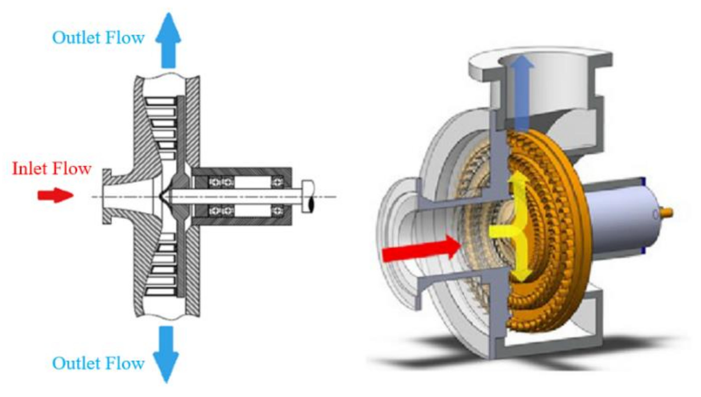
The radial outflow turbine can be used to simultaneously make up for the disadvantages of the axial turbine and the radial inflow turbine [2,3]. Figure 1 shows the typical structure of a radial outflow turbine [8]. In the turbine, the working fluid flows in the axial direction and then expands in the radial direction.
The radial outflow turbine has the following advantages [5,9]. First, the turbine can have a constant height because the flow area also rises with radius during expansion of the working fluid. Second, as there is no change in velocity triangle between the hub and tip, the blades do not have to be twisted. Lastly, there is no restriction on pressure ratio, because the multi-stage configuration is easy. As such, radial outflow turbines can respond well to both fabrication and versatility for operating conditions at the same time. Therefore, studies on radial outflow turbines are being conducted gradually.
Persico et al. [10] studied a design technique of a radial outflow turbine for a 1 MW organic Rankine cycle. The study found that the intrinsic diverging form of the radial outflow configuration makes the blade design difficult. Pini et al. [11] designed radial outflow turbines consisting of three stages and six stages, respectively. The six stages operated at subsonic or weak supersonic conditions, and the preliminary design and computational fluid dynamics (CFD) results showed good agreement. On the other hand, the three stages operating at supersonic conditions had a deviation between the preliminary design and CFD results. Casati et al. [12] studied radial outflow turbines for a 10 kW organic Rankine cycle. The study showed that radial outflow turbines are suitable as efficient expanders in mini-organic Rankine cycles. Persico et al. [13] analyzed the flow patterns seen in the stator and rotor of radial outflow turbines. Persico et al. [14,15] presented optimization techniques of the blade shape for radial outflow turbines. The optimization technique was developed in-house and showed that it is useful for improving blade shape. Luo et al. [9] designed a radial outflow turbine for a supercritical carbon dioxide cycle. The turbine was optimized to meet the design requirements. Luo et al. [16] studied a three-stage radial outflow turbine with reference to the design conditions of a four-stage axial turbine. The study showed that the performance of the radial outflow turbine under design conditions was almost identical to that of the axial turbine. Song et al. [17] designed and optimized the radial outflow turbines using R123 from one stage to three stages, respectively. The study showed that optimized turbines have similar power and efficiency between preliminary design and CFD results. Wang et al. [5] presented guide vane and volute design techniques for radial outflow turbines. In the study, the performance of the turbine was not significantly different according to the type of volute, but the pear-shaped volute showed slightly higher performance than the others. Wang et al. [18] and Liu et al. [19] studied single-stage transonic turbines for organic Rankine cycles. The studies suggested alternatives to multi-stage turbines in response to cycles requiring high pressure ratios. Al Jubori et al. [20] studied an axial turbine and a radial outflow turbine for the organic Rankine cycle. The performance of each turbine was compared through CFD, but the difference was insignificant. Maksiuta et al. [21] presented a unique preliminary design technique for multi-stage radial outflow turbines with different enthalpy drops of each stage. The radial outflow turbine designed with this technique has an 11% mechanical output power improvement over the original radial inflow turbine. There are only a few studies of radial outflow turbines, and information on the design procedure is insufficient in the abovementioned studies. Specifically, variables such as the basis of the selected rpm and blade number, the variables for which the iterative calculation was performed, the loss model used, and the accuracy of the developed design algorithm were not clearly presented. In addition, too many variables are optimized to meet the target performance, and the procedure is very complicated.
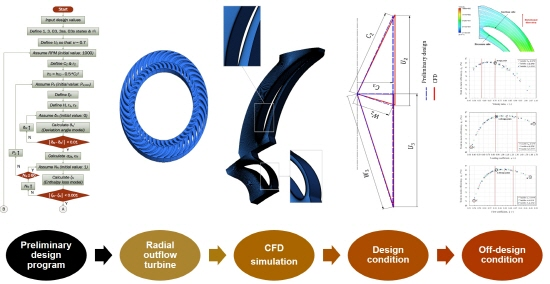
This study clearly presents a preliminary design algorithm for a radial outflow turbine to meet the target performance of turbines. The preliminary design algorithm for the radial outflow turbine proposed in this study corresponds to a new approach based on the enthalpy loss models and the deviation angle models. The developed preliminary design algorithm shows satisfactory accuracy, which greatly simplifies the optimization process to fully meet the design goals. In addition, off-design analysis is performed in this study for the designed turbine, and the flow variables that dominate the turbine efficiency are considered.
2. Preliminary Design for a Radial Outflow Turbine
2.1. Basic Theory
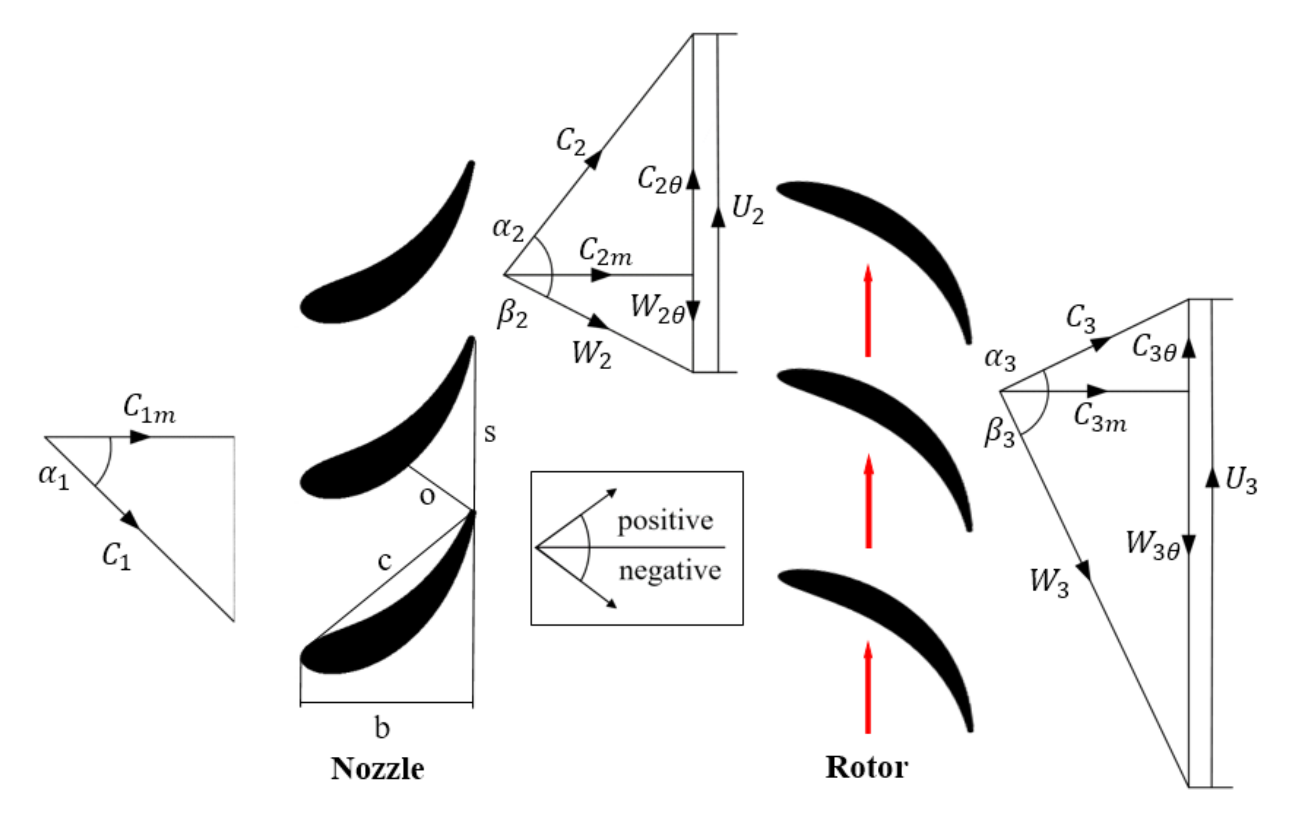
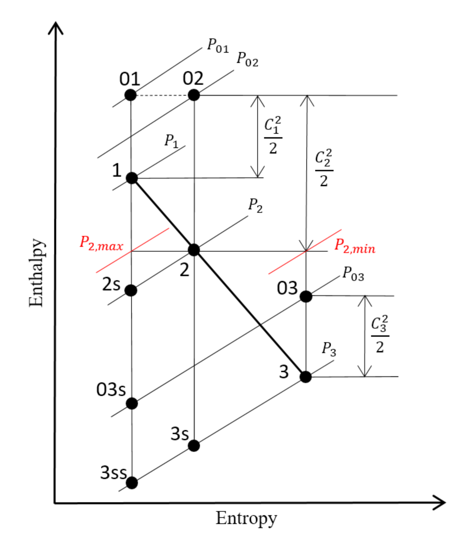
The basic concepts required for the preliminary design algorithm and performance analysis of a radial outflow turbine are as follows. The turbine stage velocity triangle and enthalpy–entropy diagram of a radial outflow turbine are shown in Figure 2 and Figure 3, respectively.
The total power of the turbine can be expressed as Equation (1) with the Euler equation and total enthalpy drop [22]. A radial outflow turbine does not have the same peripheral velocity at the inlet and exit of the rotor. In the radial outflow turbine, it is necessary to minimize the tangential absolute velocity of the rotor exit () in order to maximize the specific power of the turbine. The mass flow rate of Equation (1) is equal to Equation (2).
The total-to-total efficiency () and total-to-static efficiency () of the turbine are as follows in Equations (3) and (4), respectively. In addition, the total state enthalpy () and static state enthalpy () have the relationship of Equation (5) at a specific point.
Maksiuta et al. [21] found that radial outflow turbines, as well as radial inflow turbines, had an appropriate velocity ratio () of 0.7. The velocity ratio is defined in Equation (6). Here, the peripheral velocity of the rotor inlet () and spouting velocity () are shown in Equations (7) and (8), respectively.
The definitions of the nozzle enthalpy loss coefficient () and rotor enthalpy loss coefficient () of a radial outflow turbine are as shown in Equations (9) and (10), respectively [23]. The total-to-total efficiency () and total-to-static efficiency () of the turbine can be expressed by using the enthalpy loss coefficients shown in Equations (11) and (12) [20,22].
2.2. Algorithm of Preliminary Design Program
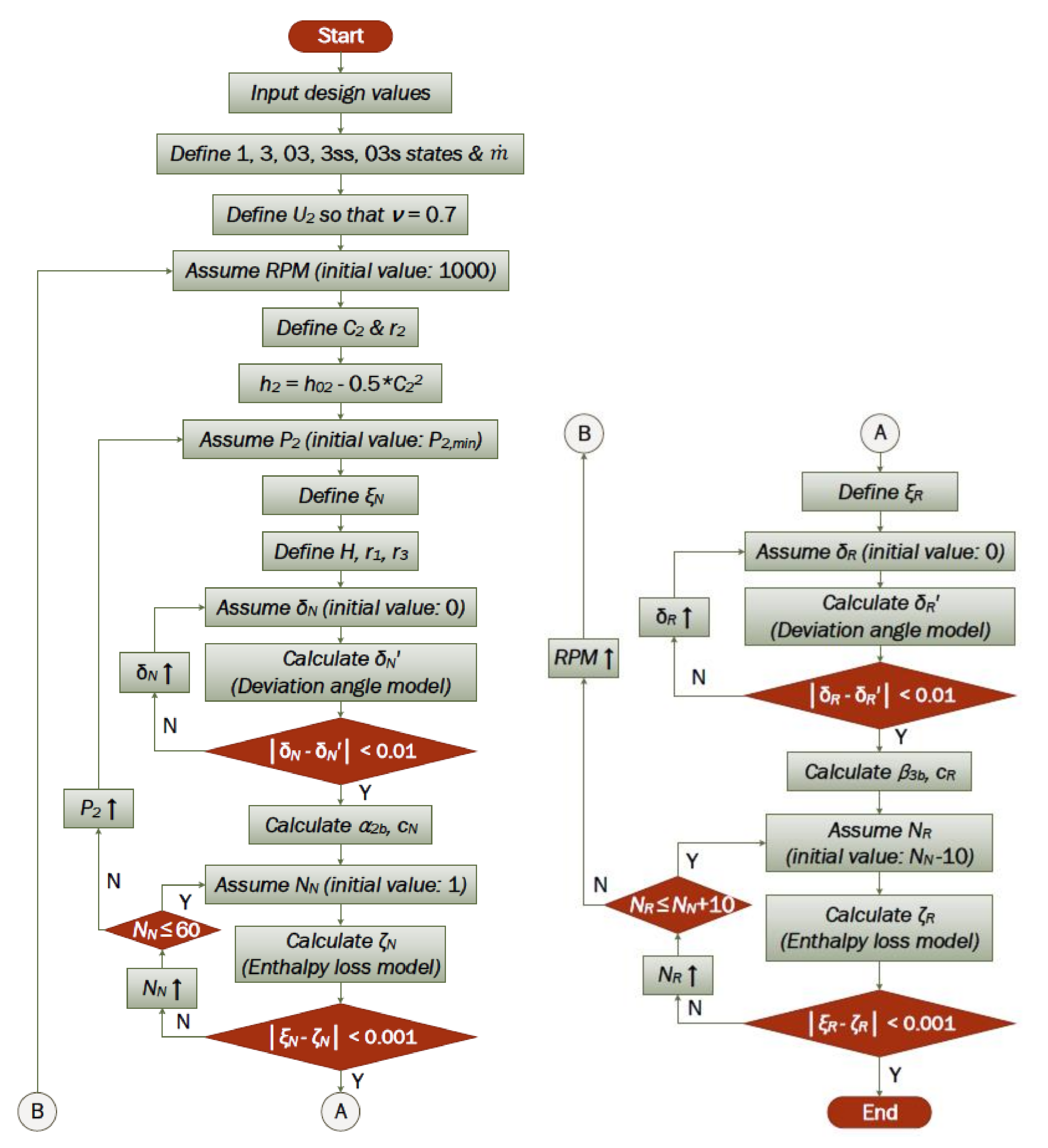
Figure 4 shows the flow chart of the preliminary design algorithm presented in this study for ORC radial outflow turbines. This program was developed with MathWorks MATLAB R2016a [24], and the state of the working fluid is based on Nist Refprop V9.1 [25]. The algorithm embedded in the program performs the preliminary design of the turbine based on the following assumptions.
- Standard stage is applied.
- The meridian absolute velocity is constant.
- The height of the blades () is constant.
- The velocity ratio is 0.7.
In order to satisfy the design conditions, the preliminary design program determines the main specifications of the radial outflow turbine such as the length, angle, and number of blades through iterative calculation.
The loss model used in the preliminary design algorithm is Soderberg’s correlation [22,26]. It is an equation created from many experimental results, and it is known that the error for a wide range of Reynolds numbers is as low as 3%.
The nominal loss coefficient () represents the loss when the blade has an aspect ratio () of 3 and Reynolds number of 105. The nominal loss coefficient () can be expressed as Equation (15).
If the aspect ratio () is not 3, the loss coefficients () for the nozzle blade and the rotor blade can be expressed by Equations (16) and (17), respectively.
For the nozzle blade,
for the rotor blade,
If the Reynolds number is not 105, the loss coefficient () corrected by the Reynolds number can be obtained through Equations (18)–(20).
where
The deviation angle model of the blade can be expressed as Equations (21)–(24) with reference to Aungier [27].
where
3. Validation of the Preliminary Design Program
3.1. Design Condition
For validation of the preliminary design program, a radial outflow turbine was designed. The design condition was referenced by the studies of Kim [2] and Sauret et al. [28], and the main design variables are shown in Table 1. In consideration of manufacturability, the thickness–chord ratio () of the nozzle blade and rotor blade was selected to be 0.25 and 0.10, respectively.
3.2. Results of Preliminary Design
As the preliminary design result for the design conditions in Table 1, the RPM range that satisfies the high accuracy required and design conditions was 7100–7300 RPM. Table 2 shows the main specifications of the radial outflow turbine according to RPM. Excluding the number of nozzle blades and rotor blades, there is no significant difference in turbine shape according to RPM. Meanwhile, the local power grid generally uses a frequency of 60 Hz. In this study, 7200 RPM, which is easy to convert to frequency, was determined as the RPM of the turbine.
3.3. Method of CFD Analysis
The preliminary design program of the radial outflow turbine was validated using CFD. It is an effective, economical, and reliable tool for validating the preliminary design program of turbomachinery.
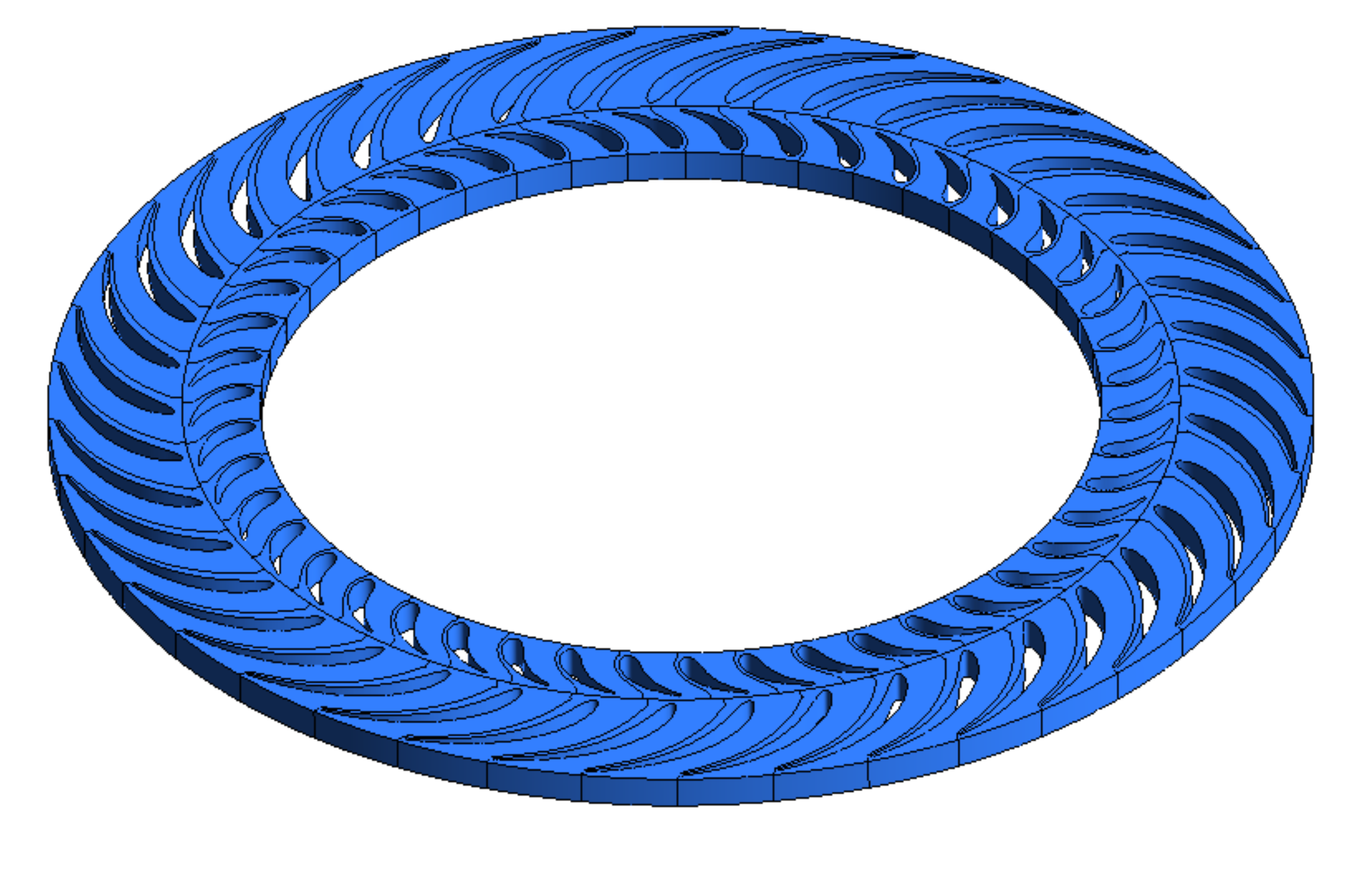
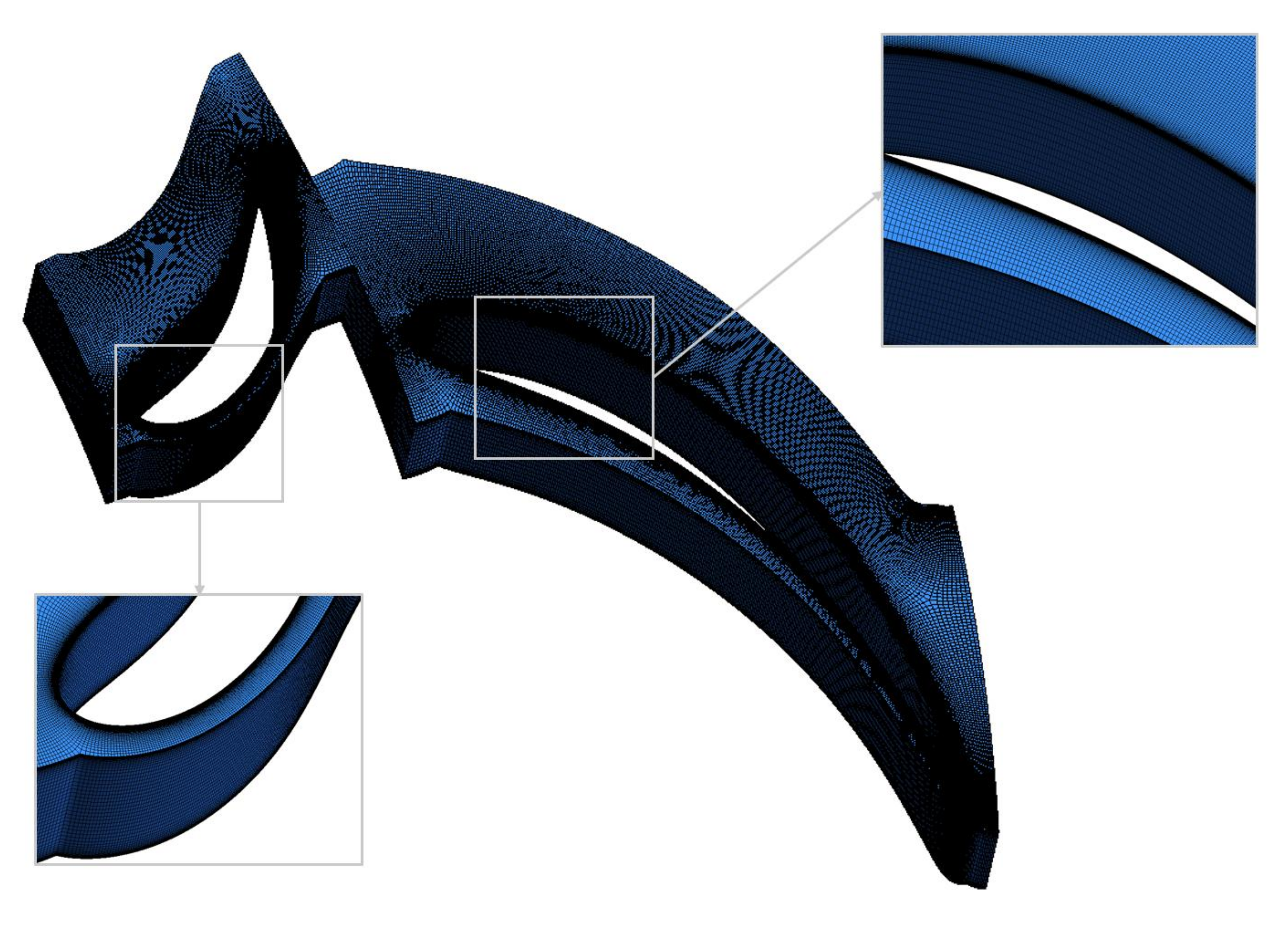
ANSYS-BladeGen V13.0 was used to complete the full geometry of the radial outflow turbine corresponding to the preliminary design results of 7200 RPM (Figure 5). The blade angle was set to change linearly over the flow path. The 4-digit NACA thickness model provided by ANSYS-BladeGen was applied for the nozzle and rotor blades in Table 2 [29]. For effective validation, analysis was performed on the one-passage geometry of the nozzle and rotor. A hexagonal mesh was created using ANSYS-TurboGrid V13.0 based on the one-passage geometry of the nozzle and rotor, as shown in Figure 6 [30].
ANSYS-CFX V13.0 was used as the CFD analysis program. The equation of state for the working fluid R143a used the reliable Aungier–Redlich–Kwong equation even near the critical condition [27]. The turbulence model used the shear stress transport (SST) model, which can expect more accurate flow predictions than the k–ε model in the boundary layer. The physical time step was set to according to the ANSYS-CFX V13.0 reference guide [31]. Considering that it is one passage, inlet boundary conditions were given mass flow (0.90 kg/s = 41.45 kg/s ÷ 46 passages) and total temperature (413.0 K). The exit boundary condition was given static pressure (3.4 MPa). The rotational speed of the rotor domain was 7200 RPM, the same as the preliminary design condition. The interface between the nozzle domain and the rotor domain set the frozen rotor model.
3.4. Results of CFD Analysis
Table 3 compares the CFD analysis results to the preliminary design results. CFD validation results were generally satisfactory but showed about 5% error in turbine power (). This is because the working fluid is not sufficiently accelerated at the nozzle blade, and the tangential absolute velocity of the nozzle exit () is somewhat lower compared to the preliminary design result.
4. Optimization of Velocity Triangles
4.1. Optimization Procedure
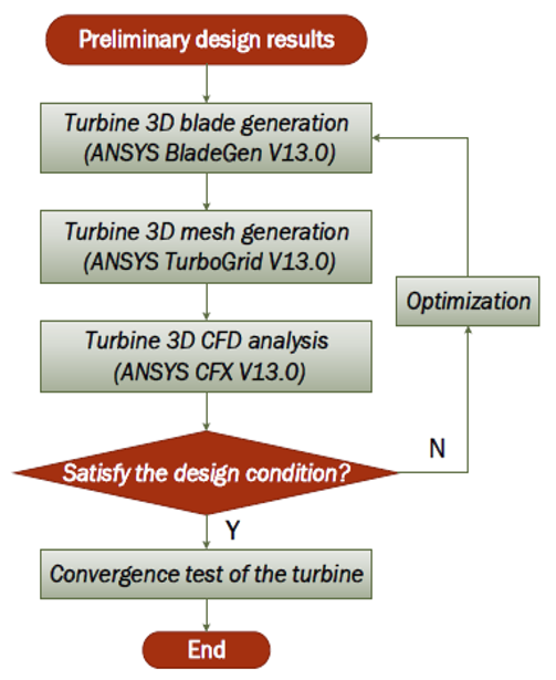
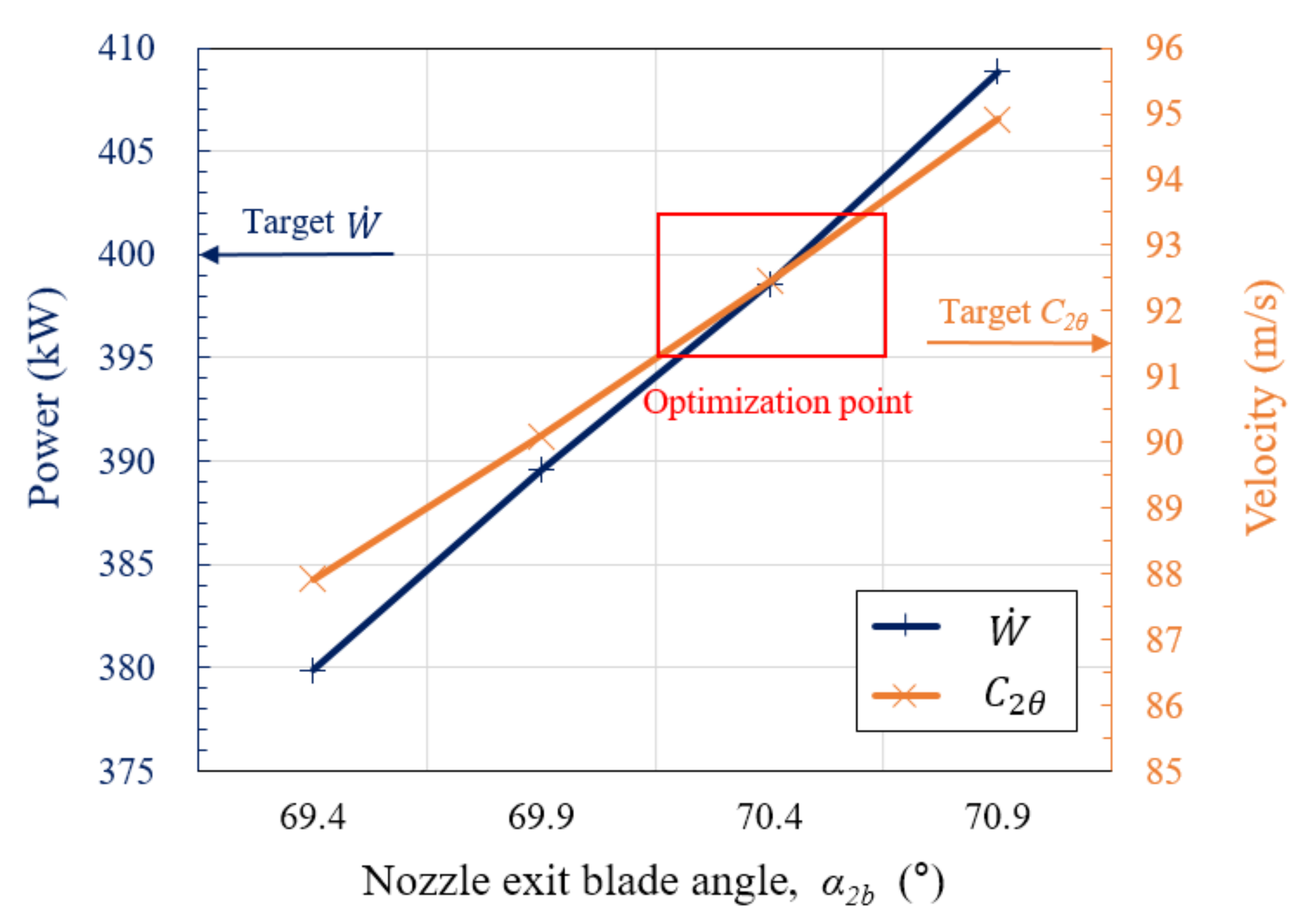
As turbines have a significant impact on the overall efficiency of the cycle, ORC developers have generally provided clear targets of turbine power and efficiency. If the performance of the actual turbine is better or worse than that required by the developer, the cycle efficiency may deteriorate as the operating conditions of the evaporator, condenser, and pump move away from the design condition. Hence, the designed turbine must meet the targets exactly. In this study, optimization was performed to satisfy the velocity triangle of each point and design goals suggested by the preliminary design program. The optimization process established in this study is shown in Figure 7. In order to increase the tangential absolute velocity of the nozzle exit (), the blade angle of the nozzle exit () was selected as an optimization variable. The other dimensions in Table 2 were not changed for the optimization.
4.2. Optimization of the Radial Outflow Turbine
Figure 8 shows the turbine power () and the tangential absolute velocity of the nozzle exit () according to the blade angle of the nozzle exit (). The turbine power () and the tangential absolute velocity of the nozzle exit () suggested by the preliminary design program are 400.0 kW and 91.5 m/s, respectively.
Looking at Figure 8, when was 69.4°, and were somewhat different from the design goals. However, at the fine-tuned 70.4°, and were 398.57 kW and 92.4 m/s, respectively. Table 4 shows the comparison between the preliminary design results and the CFD results when the was 70.4°. The CFD results were very close to the preliminary design results.
5. Performance of Final Geometry
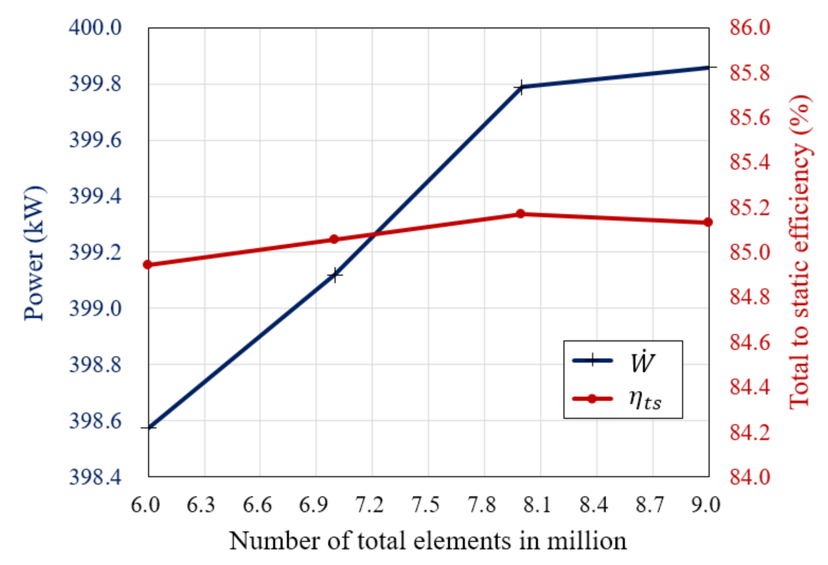
5.1. Convergence Test
5.2. Final Performance
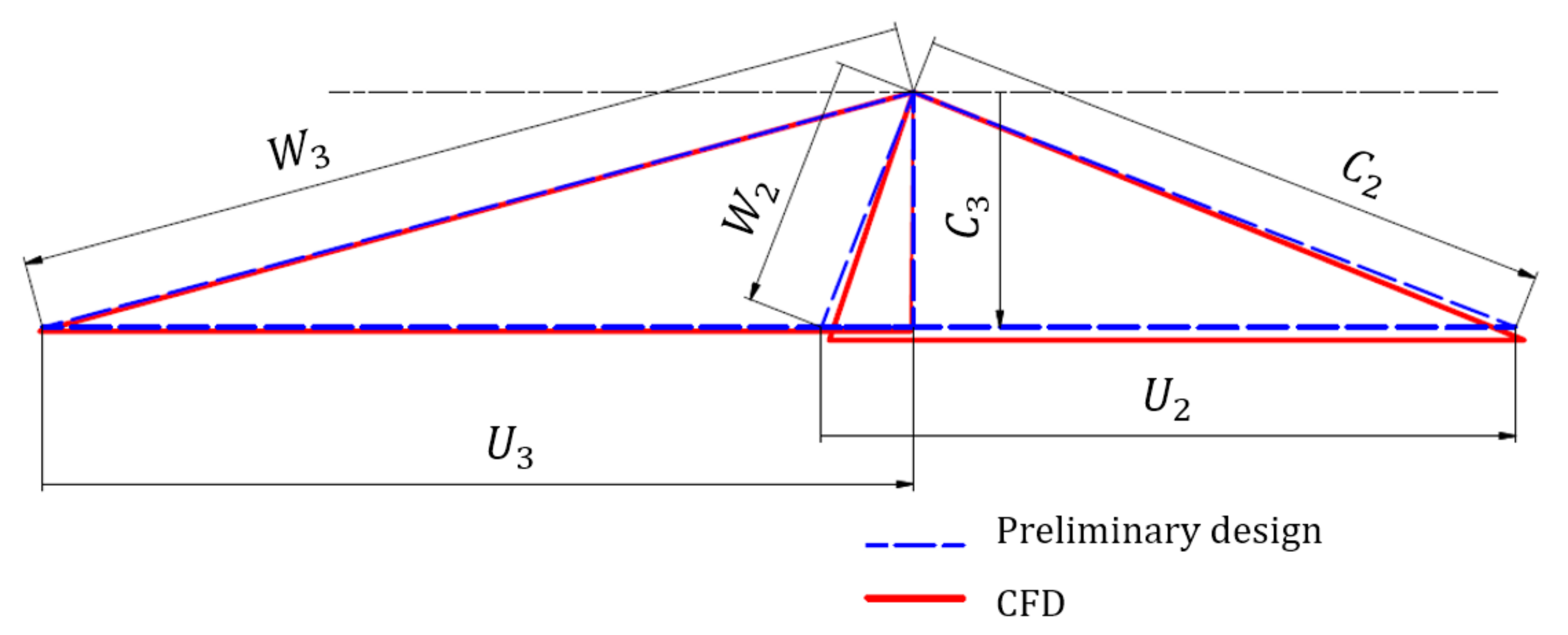
Figure 10 shows the velocity triangles of the preliminary design results and final CFD results expressed on a real scale. As a result, the velocity triangles of each other were very similar. Table 6 compares the main results of the preliminary design and the CFD. As a result, not only the velocity triangles of the turbine, but also the turbine power, total-to-static efficiency, pressure ratio, temperature ratio, and Mach number were very close. The final performance of the optimized turbine shows satisfactory results.
6. Off-Design Analysis of the Radial Outflow Turbine
6.1. Off-Design Analysis
The performance of the designed radial outflow turbine was analyzed in off-design conditions. Table 7 shows the start, end, and step values in the variable change for the off-design analysis, and a total of 75 cases of off-design analysis results were obtained.
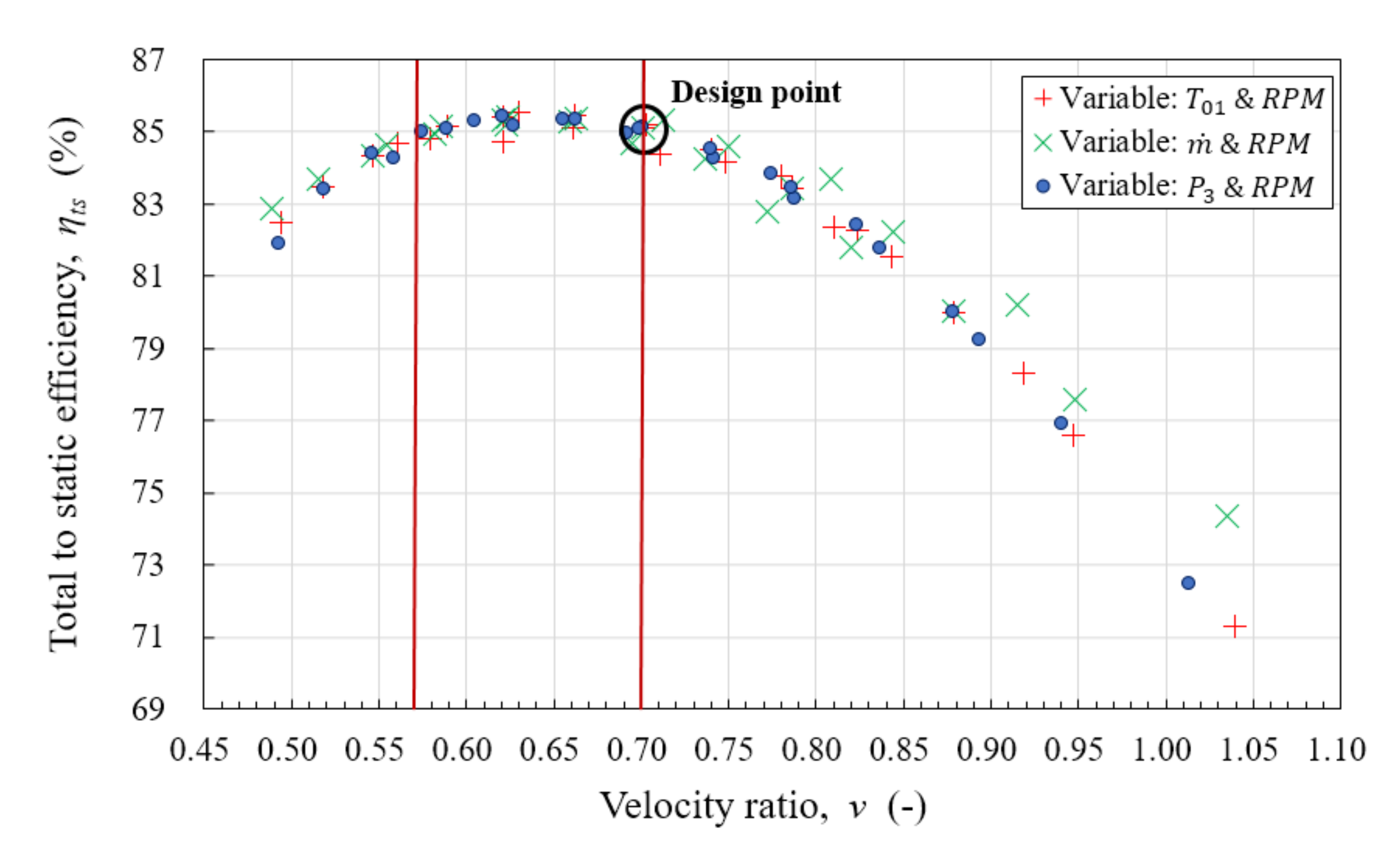
6.2. Total-to-Static Efficiency () versus Velocity Ratio ()
Figure 11 shows the total-to-static efficiency () of the turbine according to the velocity ratio (). The range of velocity ratios that can expect high efficiency over 85% is 0.57–0.70. The velocity ratio of 0.7 and of 85% assumed in the preliminary design were an appropriate selection.
6.3. Total-to-Static Efficiency () versus Loading Coefficient () and Flow Coefficient ()
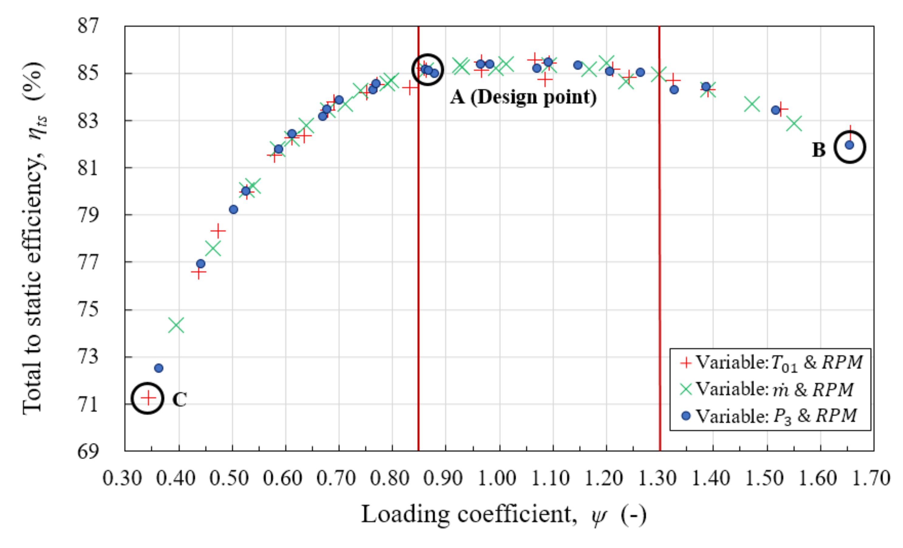
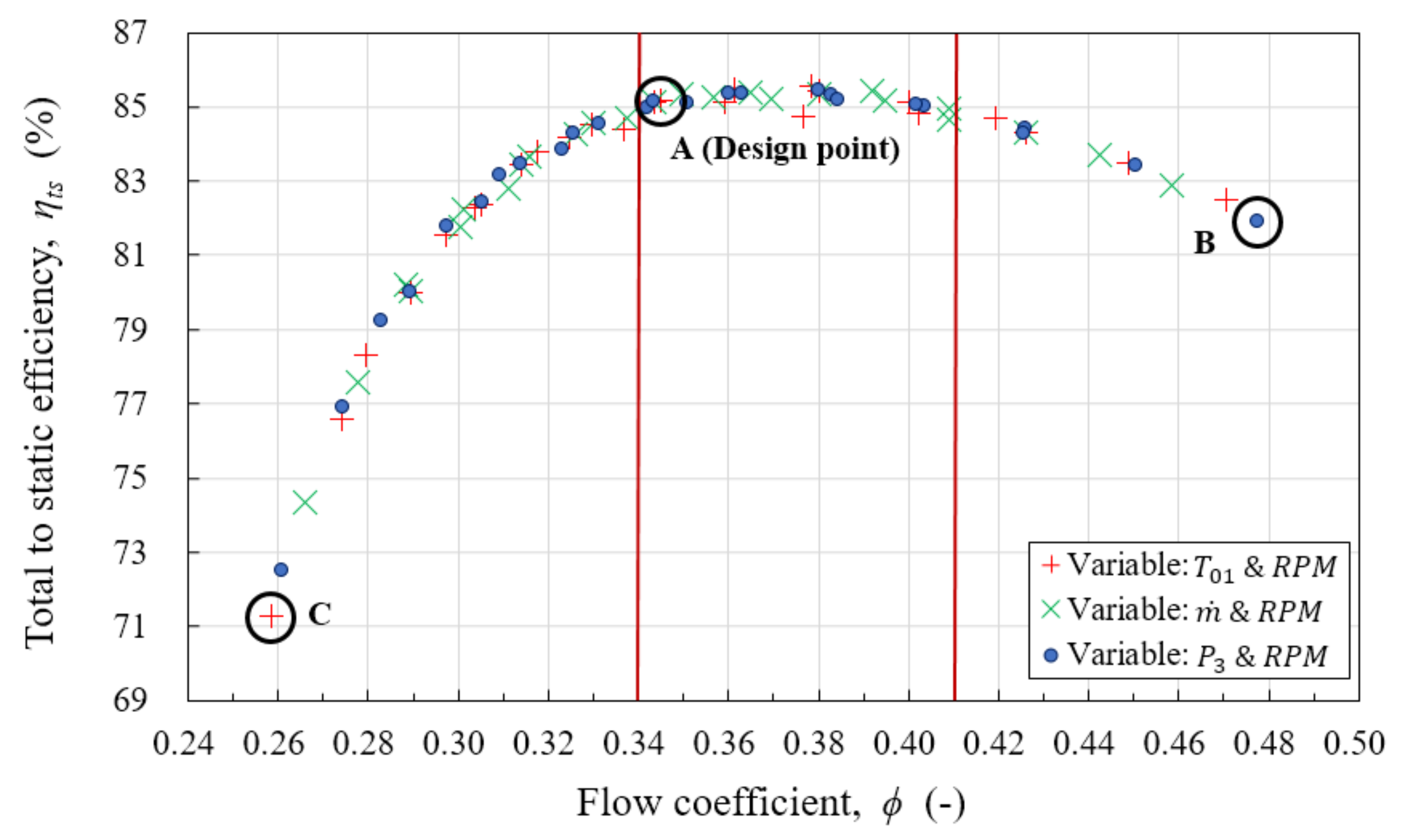
Figure 12 and Figure 13 are the performance curves according to the loading coefficient () and the flow coefficient (). The ranges of loading coefficient and flow coefficient showing high efficiency over 85% are 0.85–1.30 and 0.34–0.41, respectively. The loading coefficient and the flow coefficient of the turbine obtained in the preliminary design were 0.87 and 0.34, respectively. CFD results obtained from the final geometry of the turbine have a loading coefficient of 0.86 and flow coefficient of 0.34, and the values of each dimensionless variable are almost identical.
In Figure 12 and Figure 13, A corresponds to the design condition and the operating condition that can expect high efficiency. When the operating conditions are directed to B, the efficiency drops gently. On the other hand, if the operating conditions are directed to C, the efficiency drops sharply.
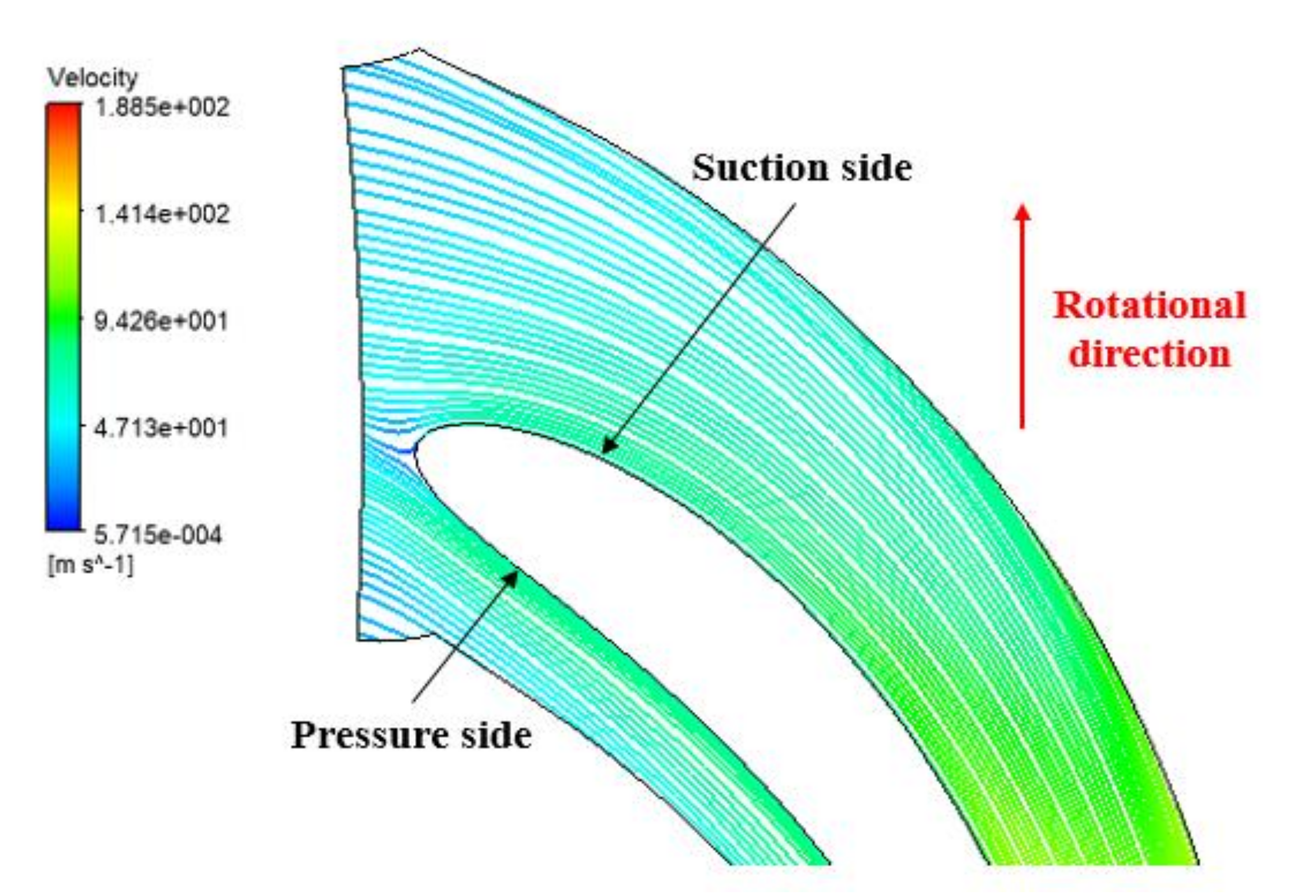
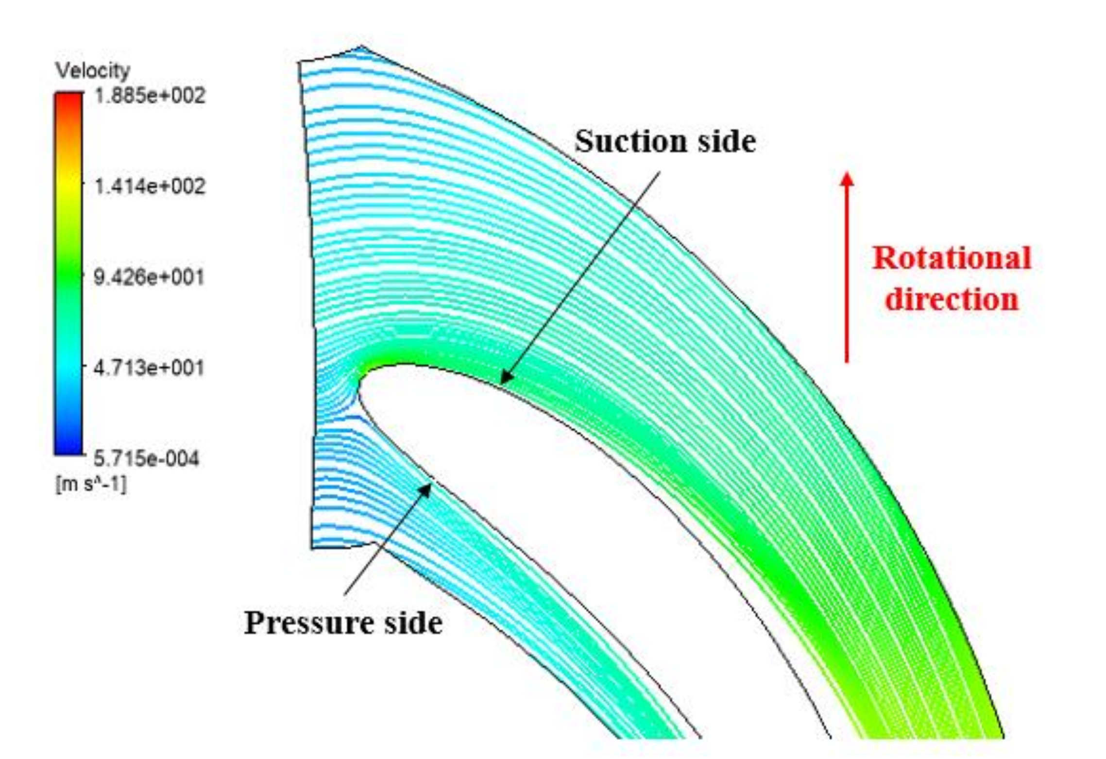
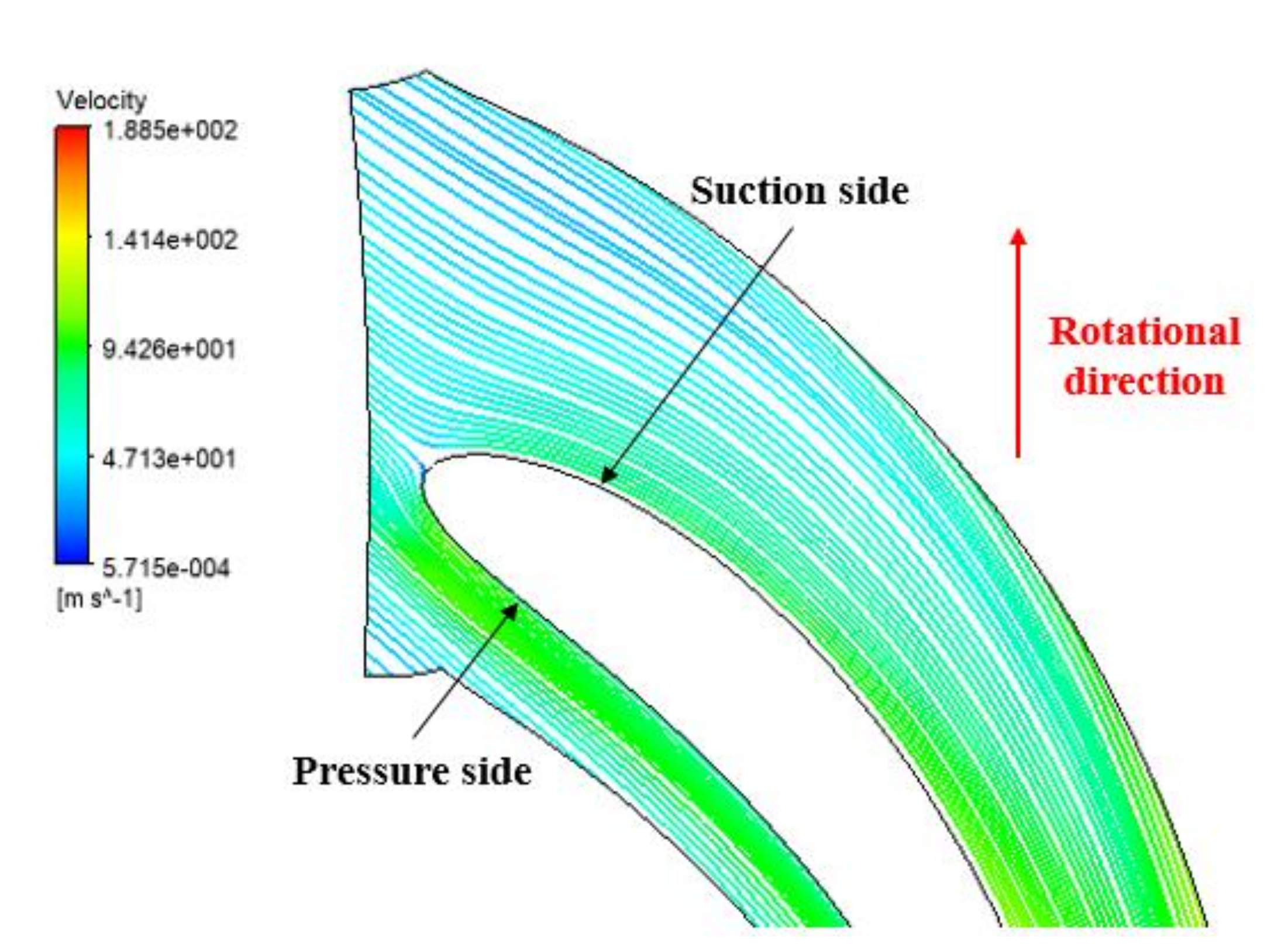
Figure 14, Figure 15 and Figure 16 show the streamlines around the rotor blade when the operating conditions are A, B, and C, respectively. At the A point, the inlet flow almost flows along the shape of the rotor blade (Figure 14). At the B point, the inlet flow is directed toward the pressure side of the rotor blade (Figure 15). On the other hand, at the C point, the inlet flow is directed toward the suction side of the rotor blade (Figure 16).
Table 8 shows the incidence angle () and more specific information of each operating condition. The incidence angle of the rotor at the A point is 2.3°, so there is no significant difference between the blade angle of the rotor inlet () and the flow angle (). The B point has an incidence angle of 32.9°, which means that the rotor inlet flow faces the pressure side excessively. Meanwhile, the C point has an incidence angle of −20.8°, and its flow is overly directed to the suction surface.
Figure 17 shows the pressure distribution between the pressure side and the suction side of the design point (A point) and the lowest efficiency point (C point). As a result, the A point shows an appropriate pressure distribution along the radial direction, but the C point shows an inappropriate pressure distribution on the pressure side and the suction side. Looking at the pressure distribution for the C point, there is an area where the pressure on the suction side is higher than the pressure on the pressure side, and the net force in this area acts in the opposite direction of the rotational direction. As the operating conditions approach the C point, the rotor inlet flow is progressively directed to the suction side, which leads to an improper pressure distribution. Accordingly, a sharp decrease in the total-to-static efficiency occurs between A and C points.
7. Conclusions
In this study, a preliminary design algorithm for ORC radial outflow turbines was presented. This algorithm uses models of axial turbines due to the absence of enthalpy loss models and deviation angle models for radial outflow turbines. As a result of evaluating the algorithm through CFD, the algorithm showed an accuracy of about 95% based on the turbine power. That is, it was realized that models derived from the axial turbine are also effective in the preliminary design of the radial outflow turbine. Due to the high accuracy of the algorithm developed in this study, the designed turbine could satisfy the target power (400.0 kW) and total-to-static efficiency (85.0%) by fine-tuning the blade angle of the nozzle exit. In addition, the off-design performance for various operation conditions was examined in this study. Through off-design analysis, it is considered that the appropriate ranges of velocity ratio, loading coefficient, and flow coefficient that can expect high efficiency in a radial outflow turbine are 0.57–0.70, 0.85–1.30, and 0.34–0.41, respectively. The findings of this study are expected to be a useful reference in the design of radial outflow turbines for organic Rankine cycles.
Author Contributions
Conceptualization, J.S.K. and D.Y.K.; methodology, J.S.K. and D.Y.K.; software, J.S.K. and D.Y.K.; validation, J.S.K.; formal analysis, J.S.K. and D.Y.K.; investigation, J.S.K. and D.Y.K.; resources, D.Y.K.; data curation, J.S.K.; writing—original draft preparation, J.S.K.; writing—review and editing, D.Y.K.; visualization, J.S.K. and D.Y.K.; supervision, D.Y.K.; project administration, D.Y.K.; funding acquisition, D.Y.K. All authors have read and agreed to the published version of the manuscript.
Funding
This research received no external funding.
Conflicts of Interest
The authors declare no conflict of interest.
Nomenclature
| Radial chord | Pressure | ||
| Absolute velocity | Pressure ratio | ||
| True chord | Radius | ||
| Spouting velocity | Reynolds number | ||
| Hydraulic diameter | Entropy, Pitch | ||
| Height | Temperature | ||
| Enthalpy | Blade thickness | ||
| Incidence angle | Temperature ratio | ||
| Mach number | Peripheral velocity | ||
| Mass flow rate | Relative velocity | ||
| Number of blades | Turbine power | ||
| Throat | |||
| Greeks | |||
| Absolute flow angle | Dynamic viscosity | ||
| Relative flow angle | Velocity ratio | ||
| Gauging angle | Enthalpy loss coefficient | ||
| Deviation angle | Density | ||
| Deflection angle | Flow coefficient | ||
| Loss coefficient | Loading coefficient | ||
| Efficiency | Angular velocity | ||
| Subscripts | |||
| Total state | Minimum | ||
| Total state at station 0 | Nozzle | ||
| Nozzle inlet | Rotor | ||
| Nozzle exit & Rotor inlet | Relative | ||
| Rotor exit | Isentropic | ||
| Blade | Total to static | ||
| Design point | Total to total | ||
| Meridional component | Tangential component | ||
| Maximum | |||
References
- Kim, J.-S.; Kim, D.-Y.; Kim, Y.-T. Thermodynamic analysis of a dual loop cycle coupled with a marine gas turbine for waste heat recovery system using low global warming potential working fluids. J. Mech. Sci. Technol. 2019, 33, 3531–3541. [Google Scholar] [CrossRef]
- Kim, J.-S. A Study on the Preliminary Design and Performance Analysis of Radial Outflow Turbines for a Supercritical Carbon Dioxide Power Cycle and an Organic Rankine Cycle. Ph.D. Thesis, Korea Maritime and Ocean University, Busan, Korea, February 2020. [Google Scholar]
- Kim, J.-S.; Kim, Y.-T.; Kim, D.-Y. A fundamental study on the preliminary design of a radial outflow turbine. J. Korean Soc. Mar. Eng. 2019, 43, 535–544. [Google Scholar] [CrossRef]
- Kim, J.-S.; Kim, D.-Y.; Kim, Y.-T. Experiment on radial inflow turbines and performance prediction using deep neural network for the organic Rankine cycle. Appl. Therm. Eng. 2019, 149, 633–643. [Google Scholar] [CrossRef]
- Wang, Y.; Tan, X.; Wang, N.; Huang, D. Aerodynamic design and numerical study for centrifugal turbine with different shapes of volutes. Appl. Therm. Eng. 2018, 131, 472–485. [Google Scholar] [CrossRef]
- Spadacini, C.; Rizzi, D. Radial outflow turbines for Organic Rankine Cycle expanders. In Organic Rankine Cycle (ORC) Power Systems; Elsevier: Amsterdam, The Netherlands, 2017; pp. 335–359. ISBN 9780081005118. [Google Scholar] [CrossRef]
- Bao, J.; Zhao, L. A review of working fluid and expander selections for organic Rankine cycle. Renew Sustain. Energy Rev. 2013, 24, 325–342. [Google Scholar] [CrossRef]
- Spadacini, C.; Centemeri, L.; Danieli, M.; Rizzi, D.; Xodo, L. Geothermal Energy Exploitation with the Organic Radial Outflow Turbine. World Geotherm. Congr. 2015, 2015, 1–6. [Google Scholar]
- Luo, D.; Liu, Y.; Sun, X.; Huang, D. The design and analysis of supercritical carbon dioxide centrifugal turbine. Appl. Therm. Eng. 2017, 127, 527–535. [Google Scholar] [CrossRef]
- Persico, G.; Pini, M.; Dossena, V.; Gaetani, P. Aerodynamics Design and Analysis of Centrifugal Turbine Cascades. In ASME Turbo Expo 2013: Turbine Technical Conference and Exposition, San Antonio, TX, USA, 3–7 June 2013; ASME: New York, NY, USA, 2013; p. 12. [Google Scholar] [CrossRef]
- Pini, M.; Persico, G.; Casati, E.; Dossena, V. Preliminary Design of a Centrifugal Turbine for Organic Rankine Cycle Applications. J. Eng. Gas Turbines Power 2013, 135, 042312. [Google Scholar] [CrossRef]
- Casati, E.; Vitale, S.; Pini, M.; Persico, G.; Colonna, P. Centrifugal Turbines for Mini-Organic Rankine Cycle Power Systems. J. Eng. Gas Turbines Power 2014, 136, 122607. [Google Scholar] [CrossRef]
- Persico, G.; Pini, M.; Dossena, V.; Gaetani, P. Aerodynamics of Centrifugal Turbine Cascades. J. Eng. Gas Turbines Power 2015, 137, 112602. [Google Scholar] [CrossRef]
- Persico, G.; Dossena, V.; Gaetani, P. Optimal Aerodynamic Design of a Transonic Centrifugal Turbine Stage for Organic Rankine Cycle Applications. Energy Procedia 2017, 129, 1093–1100. [Google Scholar] [CrossRef] [Green Version]
- Persico, G.; Romei, A.; Dossena, V.; Gaetani, P. Impact of shape-optimization on the unsteady aerodynamics and performance of a centrifugal turbine for ORC applications. Energy 2018, 165, 2–11. [Google Scholar] [CrossRef]
- Luo, D.; Tan, X.; Huang, D. Design and performance analysis of three stage centrifugal turbine. Appl. Therm. Eng. 2018, 138, 740–749. [Google Scholar] [CrossRef]
- Song, Y.; Sun, X.; Huang, D. Preliminary design and performance analysis of a centrifugal turbine for Organic Rankine Cycle (ORC) applications. Energy 2017, 140, 1239–1251. [Google Scholar] [CrossRef]
- Wang, N.; Sun, X.; Huang, D. Design and Analysis of a Single-Stage Transonic Centrifugal Turbine for organic Rankine cycle (ORC). J. Therm. Sci. 2019, 27, 32–42. [Google Scholar] [CrossRef]
- Liu, Y.; Huang, D. Design and performance analysis of an ORC transonic centrifugal turbine. J. Mech. Sci. Technol. 2019, 33, 1417–1430. [Google Scholar] [CrossRef]
- Al Jubori, A.M.; Al-Dadah, R.K.; Mahmoud, S.; Daabo, A. Modelling and parametric analysis of small-scale axial and radial-outflow turbines for Organic Rankine Cycle applications. Appl. Energy 2017, 190, 981–996. [Google Scholar] [CrossRef] [Green Version]
- Maksiuta, D.; Moroz, L.; Burlaka, M.; Govoruschenko, Y. Study on applicability of radial-outflow turbine type for 3 MW WHR organic Rankine cycle. Energy Procedia 2017, 129, 293–300. [Google Scholar] [CrossRef]
- Sayers, A.T. Hydraulic and Compressible Flow Turbomachines; McGraw-Hill: New York, NY, USA, 1990. [Google Scholar]
- Moustapha, H.; Zelesky, M.F.; Baines, N.C.; Japikse, D. Axial and Radial Turbines; Concepts NREC: White River Junction, VT, USA, 2003. [Google Scholar]
- MathWorks. MATLAB Version R2016a User Guide; MathWorks: Natick, MA, USA, 2016. [Google Scholar]
- NIST. Refprop Version 9.1 User Guide; NIST: Gaithersburg, MD, USA, 2013. [Google Scholar]
- Dixon, S.L.; Hall, C.A. Two-Dimensional Cascades. In Fluid Mechanics and Thermodynamics of Turbomachinery, 6th ed.; Elsevier: Amsterdam, The Netherlands, 2010; pp. 53–96. ISBN 9781856177931. [Google Scholar] [CrossRef]
- Aungier, R.H. Turbine Aerodynamics; ASME Press: New York, NY, USA, 2006. [Google Scholar]
- Sauret, E.; Gu, Y. Three-dimensional off-design numerical analysis of an organic Rankine cycle radial-inflow turbine. Appl. Energy 2014, 135, 202–211. [Google Scholar] [CrossRef] [Green Version]
- ANSYS. BladeGen Version 13.0 User Guide; ANSYS: Canonsburg, PA, USA, 2010. [Google Scholar]
- ANSYS. TurboGrid Version 13.0 User Guide; ANSYS: Canonsburg, PA, USA, 2010. [Google Scholar]
- ANSYS. CFX Version 13.0 Reference Guide; ANSYS: Canonsburg, PA, USA, 2010. [Google Scholar]
- Kim, D.-Y.; Kim, Y.-T. Preliminary design and performance analysis of a radial inflow turbine for organic Rankine cycles. Appl. Therm. Eng. 2017, 120, 549–559. [Google Scholar] [CrossRef]
- Kim, D.-Y.; Kim, Y.-T. Preliminary design and performance analysis of a radial inflow turbine for ocean thermal energy conversion. Renew. Energy 2017, 106, 255–263. [Google Scholar] [CrossRef]
Figure 1.
Typical structure of a radial outflow turbine (Adapted from [8]).
Figure 1.
Typical structure of a radial outflow turbine (Adapted from [8]).

Figure 2.
Schematic of a turbine stage velocity triangle for a radial outflow turbine (Adapted from [2]).
Figure 2.
Schematic of a turbine stage velocity triangle for a radial outflow turbine (Adapted from [2]).

Figure 3.
Enthalpy–entropy diagram of a radial outflow turbine.

Figure 4.
Flow chart of preliminary design program for a radial outflow turbine.

Figure 5.
Full geometry of the radial outflow turbine.

Figure 6.
One-passage geometry of the radial outflow turbine.

Figure 7.
Flow chart of optimization for the radial outflow turbine.

Figure 8.
CFD results according to the blade angle of the nozzle exit ().

Figure 9.
Convergence test results of the final geometry.

Figure 10.
Comparison of velocity triangles between preliminary design and CFD.

Figure 11.
Total-to-static efficiency according to the velocity ratio ()

Figure 12.
Total-to-static efficiency according to the loading coefficient ()

Figure 13.
Total-to-static efficiency according to the flow coefficient ()

Figure 14.
Streamline of the rotor blade (A point).

Figure 15.
Streamline of the rotor blade (B point).

Figure 16.
Streamline of the rotor blade (C point).

Figure 17.
Blade loading chart according to the radius of rotor blade (A point and C point).


Table 1.
Design values of a radial outflow turbine.
| Variables | Unit | Values |
|---|---|---|
| Working fluid | - | R143a |
| kW | 400.0 | |
| MPa | 5.0 | |
| K | 413.0 | |
| MPa | 3.4 | |
| % | 90.0 | |
| % | 85.0 |
Table 2.
Preliminary design results of the radial outflow turbine.
| Specification | 7100 RPM | 7200 RPM | 7300 RPM |
|---|---|---|---|
| [mm] | 121.6 | 119.9 | 118.3 |
| [mm] | 139.9 | 137.9 | 136.0 |
| [mm] | 143.9 | 141.9 | 140.0 |
| [mm] | 177.9 | 175.4 | 173.0 |
| [mm] | 9.1 | 9.2 | 9.4 |
| [mm] | 6.0 | 5.9 | 5.8 |
| [mm] | 5.8 | 5.7 | 5.6 |
| [°] | 0.0 | 0.0 | 0.0 |
| [°] | 69.4 | 69.4 | 69.4 |
| [°] | −21.5 | −21.5 | −21.5 |
| [°] | −75.0 | −75.0 | −75.0 |
| 43 | 46 | 50 | |
| 33 | 41 | 57 |
Table 3.
Comparison of results between preliminary design and CFD.
| Variables | Preliminary Design | CFD |
|---|---|---|
| [kW] | 400.0 | 379.87 |
| [%] | 85.0 | 84.66 |
| [-] | 1.47 | 1.43 |
| [m/s] | 91.5 | 87.9 |
| [m/s] | 0.0 | 0.7 |
Table 4.
Comparison of results between preliminary design and CFD at .
| Variables | Preliminary Design | CFD |
|---|---|---|
| [kW] | 400.0 | 398.57 |
| [%] | 85.0 | 84.94 |
| [-] | 1.47 | 1.45 |
Table 5.
Information of final grid.
| Domain | No. Element | Max. y+ |
|---|---|---|
| Nozzle | 4,460,365 | 9.328 |
| Rotor | 4,432,896 | 10.372 |
Table 6.
Comparison of main results between preliminary design and CFD.
| Analysis Method | [kW] | |||||
|---|---|---|---|---|---|---|
| Preliminary design | 400.0 | 85.0 | 1.47 | 1.05 | 0.58 | 0.81 |
| CFD | 399.86 | 85.13 | 1.45 | 1.05 | 0.58 | 0.79 |
| Analysis method | [m/s] | [m/s] | [m/s] | [m/s] | [m/s] | [m/s] |
| Preliminary design | 98.2 | 105.5 | 38.3 | 35.6 | 132.3 | 137.0 |
| CFD | 100.1 | 105.5 | 40.6 | 37.5 | 132.3 | 137.6 |
| Analysis method | [°] | [°] | [°] | [°] | ||
| Preliminary design | 68.7 | −21.5 | 0.0 | −74.9 | ||
| CFD | 67.9 | −19.2 | 1.9 | −74.7 |
Table 7.
Information on variable changes for off-design analysis.
| Variables | Start | Step | End |
|---|---|---|---|
| [K] | 393.0 | 10.0 | 433.0 |
| [kg/s] | 37.31 | 45.60 | |
| [MPa] | 3.06 | 3.74 | |
| 5760 | 8640 |
Table 8.
Information on the main points of the performance curves according to dimensionless variables.
Table 8.
Information on the main points of the performance curves according to dimensionless variables.
| Point | i1 | Remark | |||
|---|---|---|---|---|---|
| A point | 0.86 | 0.34 | 85.13% | 2.3° | toward the pressure side |
| B point | 1.66 | 0.48 | 81.90% | 32.9° | toward the pressure side |
| C point | 0.34 | 0.26 | 71.28% | −20.8° | toward the suction side |
1.
© 2020 by the authors. Licensee MDPI, Basel, Switzerland. This article is an open access article distributed under the terms and conditions of the Creative Commons Attribution (CC BY) license (http://creativecommons.org/licenses/by/4.0/).
Share and Cite
MDPI and ACS Style
Kim, J.-S.; Kim, D.-Y. Preliminary Design and Off-Design Analysis of a Radial Outflow Turbine for Organic Rankine Cycles. Energies 2020, 13, 2118. https://0-doi-org.brum.beds.ac.uk/10.3390/en13082118
AMA Style
Kim J-S, Kim D-Y. Preliminary Design and Off-Design Analysis of a Radial Outflow Turbine for Organic Rankine Cycles. Energies. 2020; 13(8):2118. https://0-doi-org.brum.beds.ac.uk/10.3390/en13082118
Chicago/Turabian StyleKim, Jun-Seong, and Do-Yeop Kim. 2020. "Preliminary Design and Off-Design Analysis of a Radial Outflow Turbine for Organic Rankine Cycles" Energies 13, no. 8: 2118. https://0-doi-org.brum.beds.ac.uk/10.3390/en13082118
Note that from the first issue of 2016, this journal uses article numbers instead of page numbers. See further details here.