1. Introduction
In recent years, high-speed electrified railway has reached a rapid development and has been considered as one of the economic booster indicators, granting the most secure land transportation mode in terms of freight and passenger transport [
1]. However, and unfortunately, many power quality problems are caused by electric trains. This is due to the single-phase traction power grid characteristics in which many single-phase electric locomotives introduce harmonic contents and cause imbalance in the three-phase currents. The power quality deterioration not only affects the single-phase traction power grid, but it also threatens the stability and the safe operation of the three-phase power grid. Therefore, power quality improvement is a significant factor to guarantee the safety and the economical operation of the electric trains [
2,
3,
4].
In this context, a power compensator installed on two traction feeders of the traction power grid, called, a Rail Power Conditioner (RPC) was introduced in [
5,
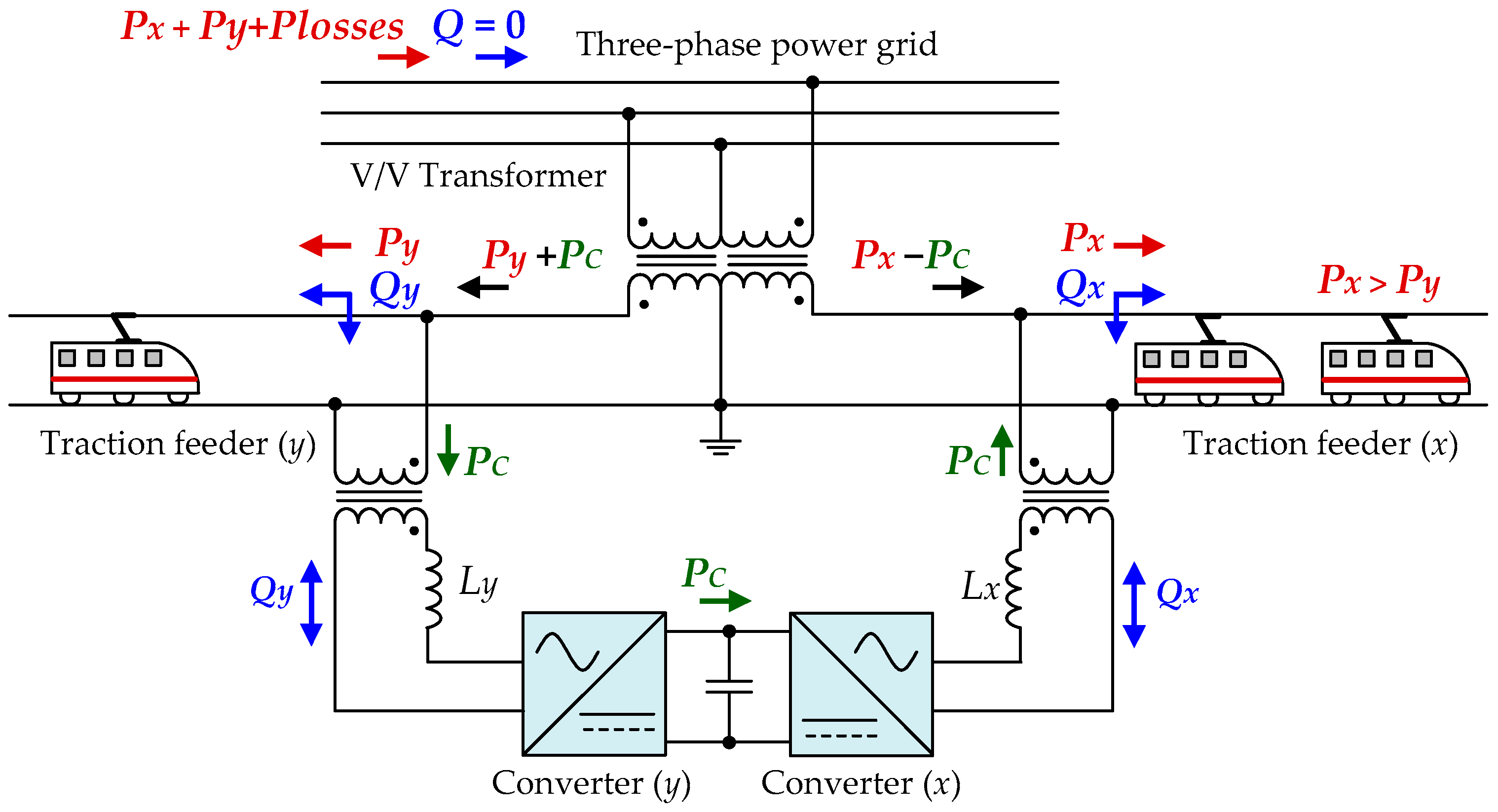
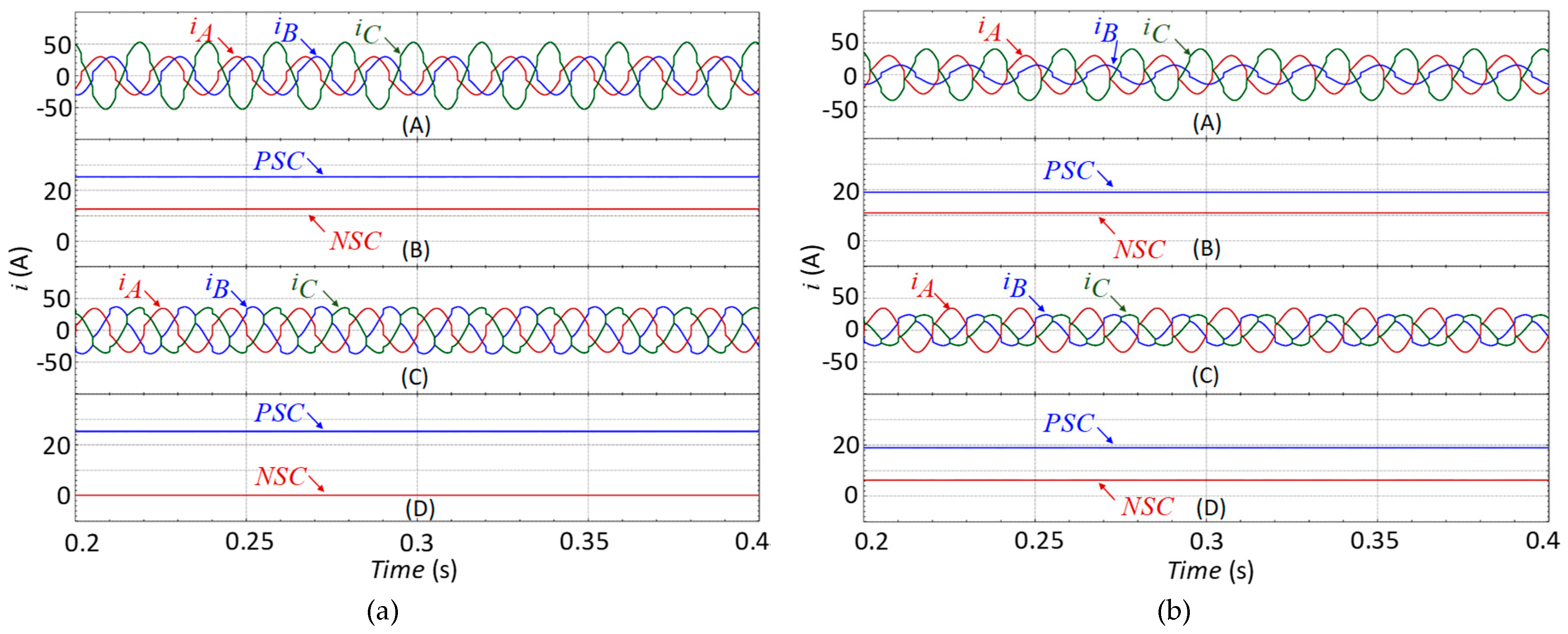
6]. In the RPC system, two power converters (one for each traction feeder) can act to compensate reactive power, thus providing the reactive power required by the traction loads and maintaining near a unitary power factor of the three-phase power grid. In addition, RPC balances the active power between the two traction feeders. Consequently, balanced three-phase currents with reduced harmonic contents and without negative sequence component (NSC) can be obtained [
6,
7,
8,
9].
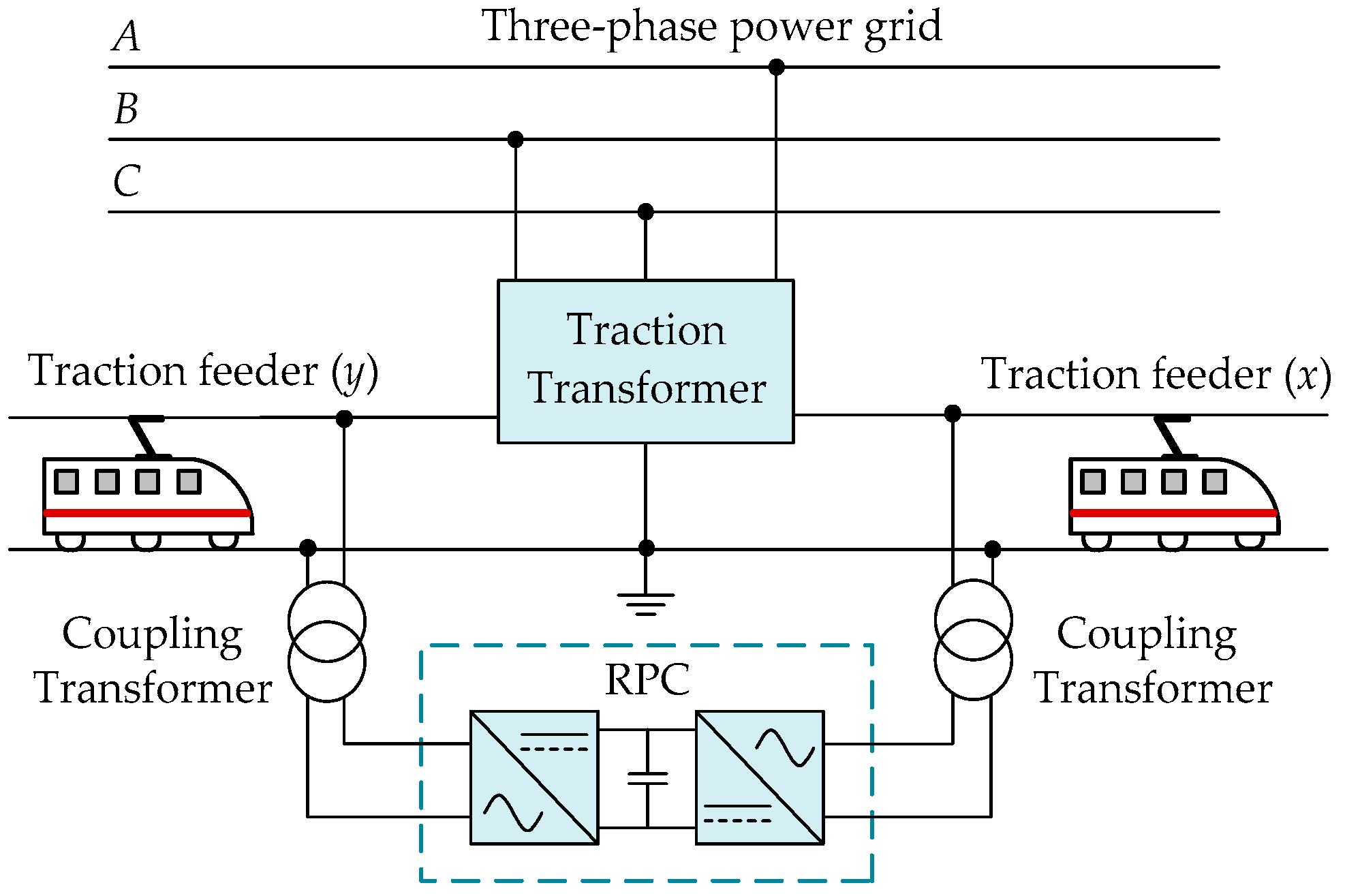
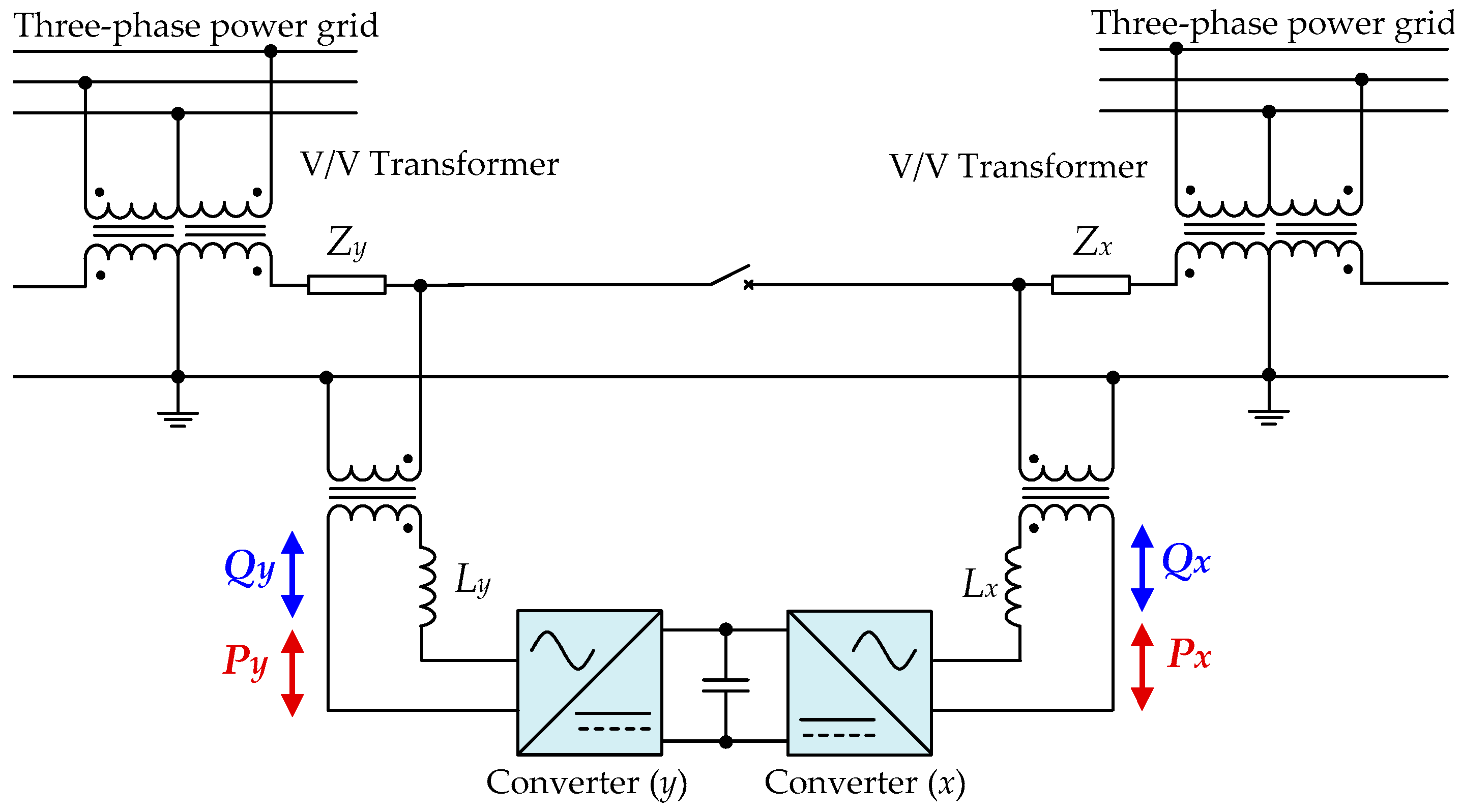
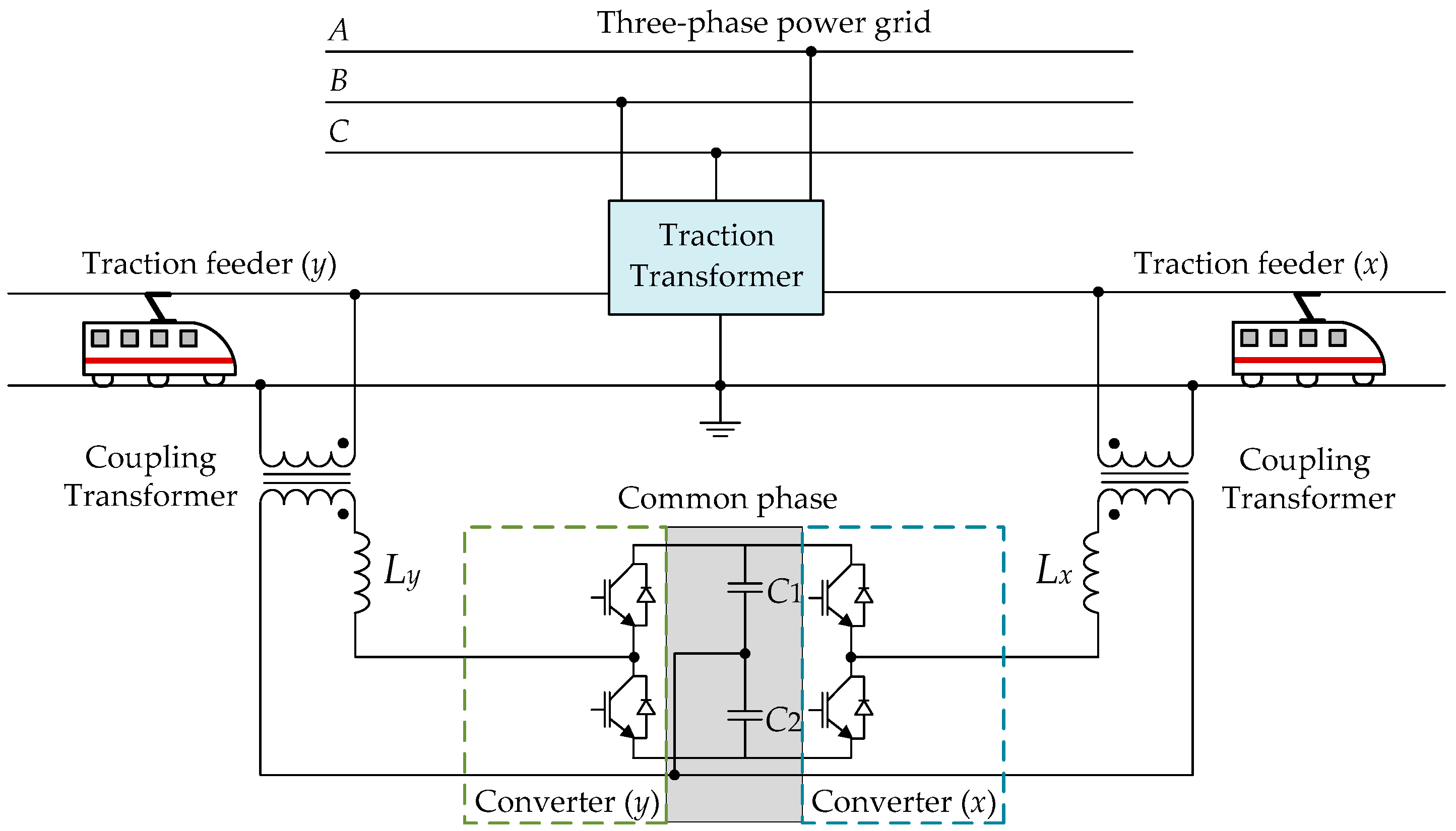
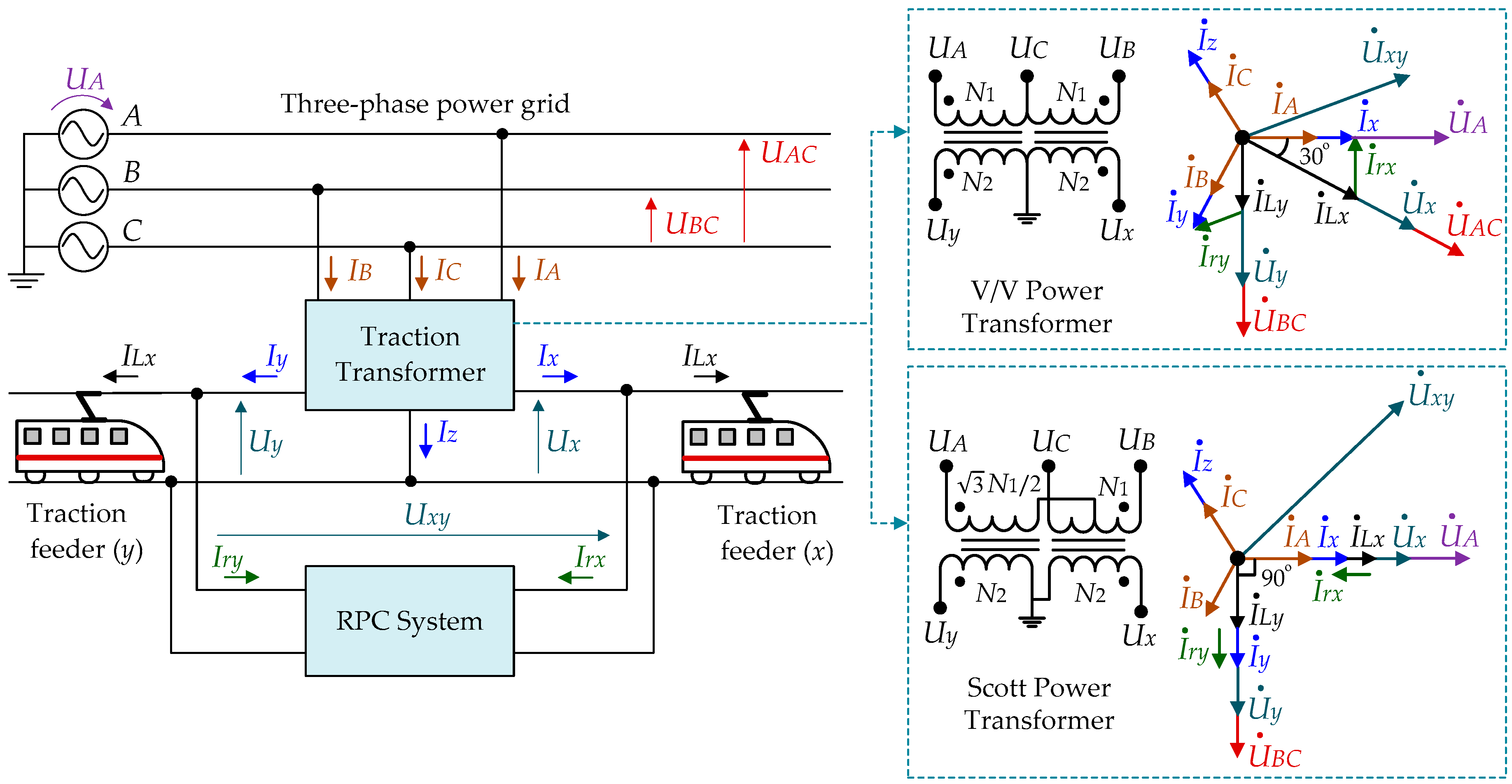
The conventional RPC system presented in
Figure 1, is composed of a full-bridge back-to-back (B2B) converter (FB-RPC), which is connected to two traction feeders through two coupling transformers (CTs). These transformers are important to achieve the required galvanic isolation between the RPC and the single-phase traction power grid, besides step-down of the traction feeders voltage [
10]. Subsequently, some improved topologies based on the FB-RPC are presented in the literature. For instance, a comprehensive analysis of the FB-RPC system based on an unbalanced open-delta (V/V) power transformer, providing simulation and experimental results, is presented in [
6]. An RPC system, based on V/V power transformer and equipped with an energy storage system, is presented in [
11], which uses a supercapacitor that is connected to the DC-link of the RPC via a bidirectional DC–DC converter. This energy storage system is useful for reducing the peak power demand and the operation costs in a railway substation. In [
12], an improved grid voltage sensorless control strategy for the RPC system is proposed to replace the AC voltage sensors by a virtual flux method based on second-order low-pass filters.
The imbalance ratio of the three-phase currents depends on the topology of the traction systems, as well as the type of power transformer [
13]. When a traction system contains a balanced power transformer (such as Scott, LeBlanc, YNvd, Woodbridge, and the impedance-matching transformers), the two-phase balanced secondary currents will result in balanced three-phase primary currents. In this context, the combination between the RPC system and the balanced power transformers is studied in [
14,
15,
16]. For instance, the combination of an RPC with YNvd transformer for co-phase traction power supply system is studied in [
14].
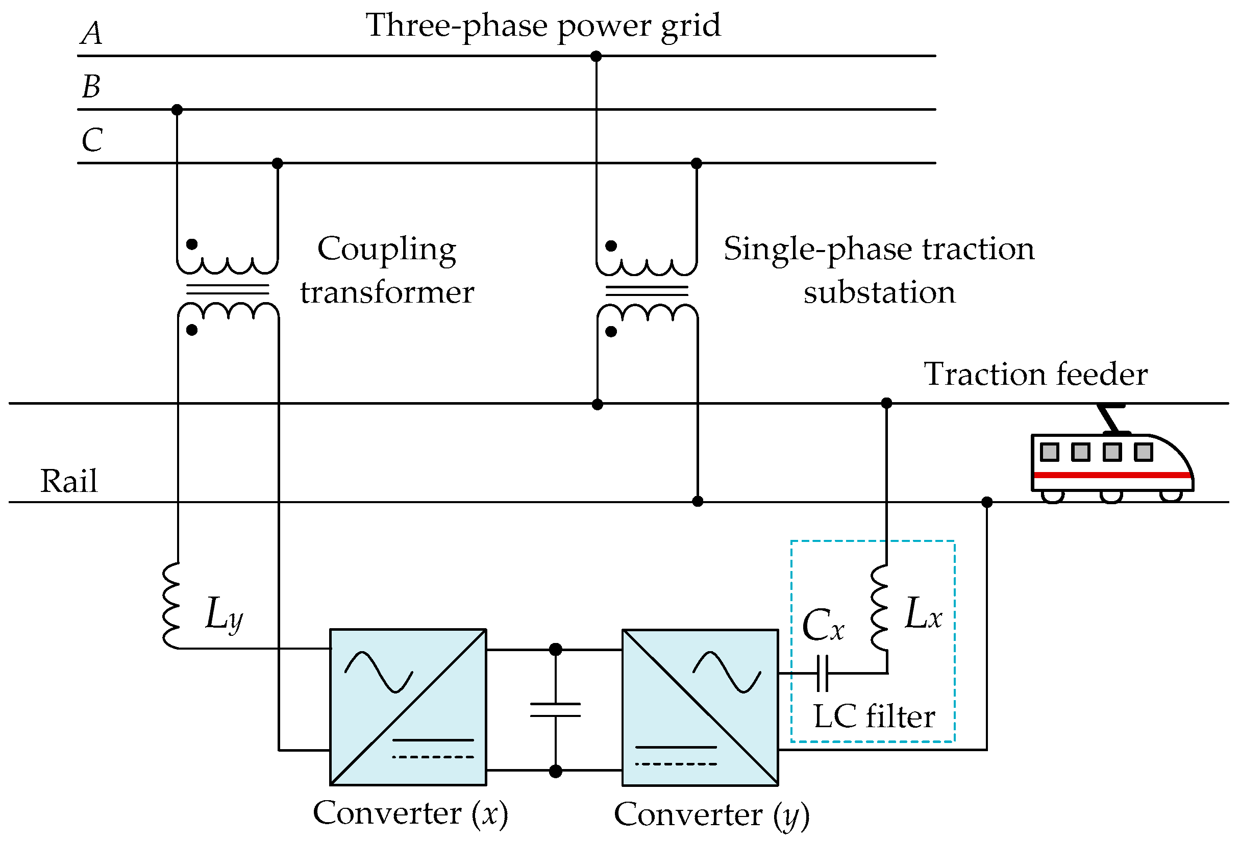
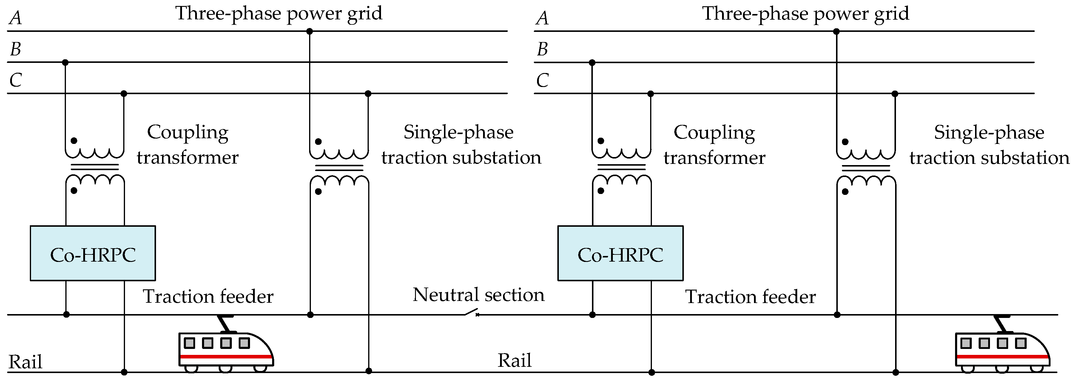
Co-phase hybrid RPC system (co-HRPC), proposed in [
16,
17,
18], is extensively studied by researchers, in which a partial compensation is adopted to reduce both the current and voltage ratings of the RPC converter. This is possible by using a capacitive-inductive structure in one coupling branch of the RPC, which improves the RPC performance. In [
19], a study recommends to include a double asymmetric capacitive-inductive structure in the two coupling branches of the RPC for a better heavy-load compensation capacity with a lower DC-link voltage. On the other hand, a flexible DC-link voltage control for the co-HRPC system is proposed in [
20] to reduce the power losses during the RPC operation, besides reducing the RPC ratings. A hybrid RPC (HRPC) system may contain additional power filters to reduce the volume and power ratings of the system. In this context, a combination of RPC and Static Var Compensator (SVC) is presented in [
21]; however, a coordinated control is necessary for two subsystems of RPC and SVC [
10]. The relationship between the DC-link voltage of the HRPC and its power quality compensation capability is presented in [
22], where the experimental results show that, the higher is the DC-link voltage of the HRPC, the better is the compensation capability achieved.
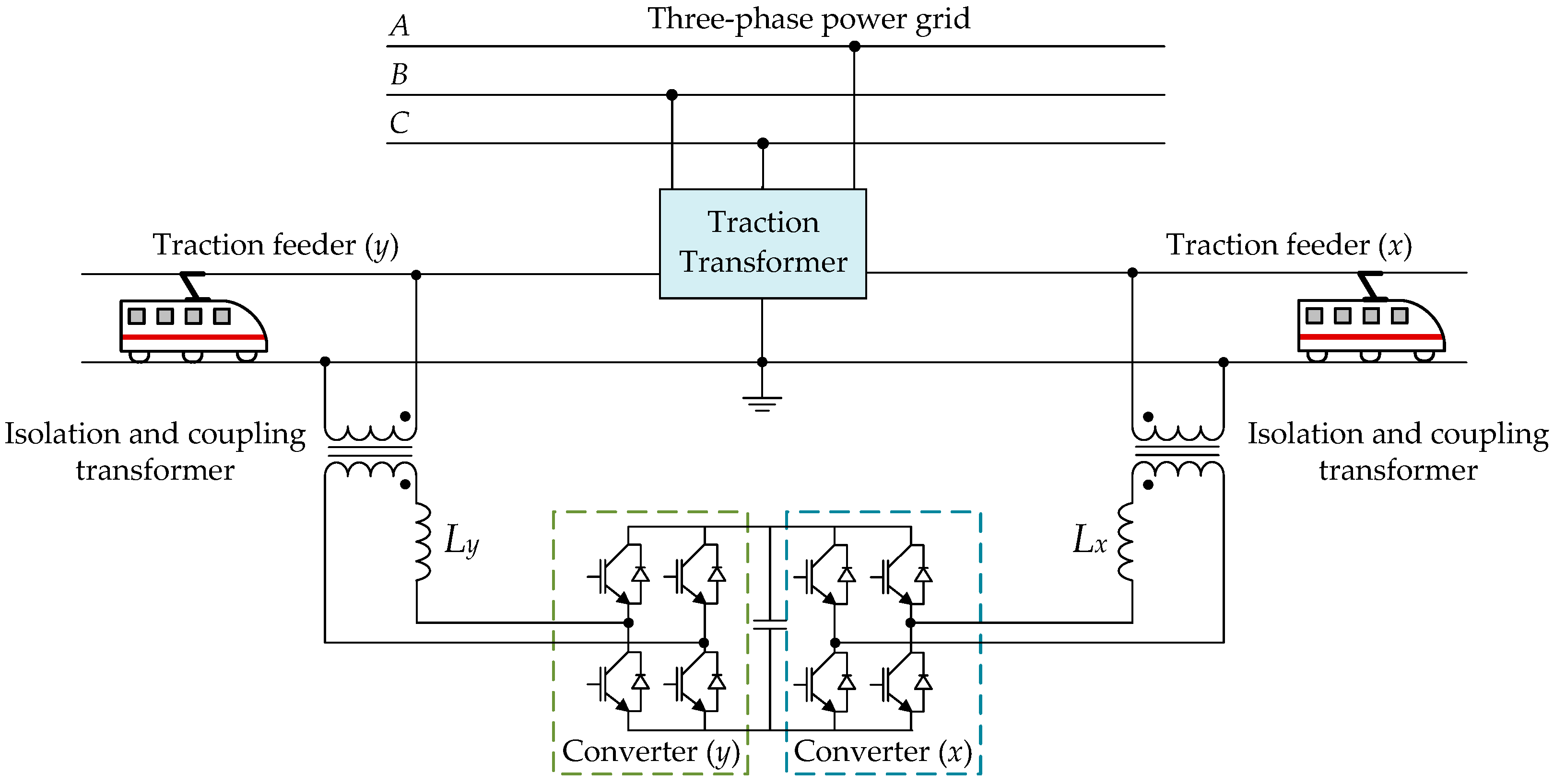
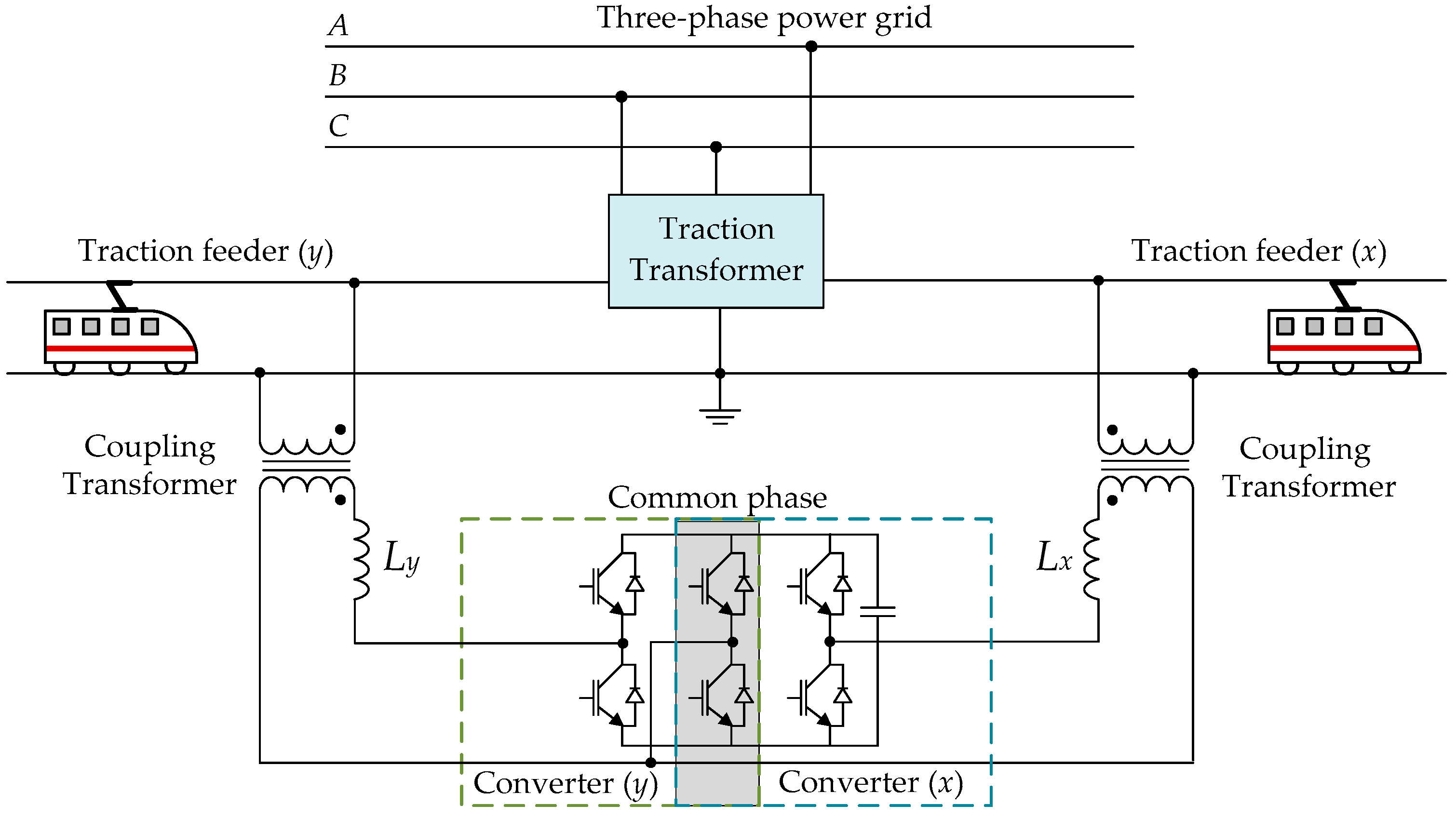
Two-phase three-wire RPC (TW-RPC) contains three switch legs, thus allowing to reduce a switch leg when compared with the FB-RPC system [
7]. In that regard, hybrid TW-RPC is presented in [
23]. In addition to this, in [
24], a quasi-Z-source TW-RPC is proposed and, in [
25], a Z-source TW-RPC is proposed to decrease the ratings of the RPC converter. In [
26], a TW-RPC with an isolation Scott transformer is proposed, which converts the two-phase traction power grid to a nearly balanced three-phase power system; this helps to reduce the RPC power ratings. On the other hand, simplified half-bridge RPC (HB-RPC) only contains two switch legs, thus allowing to reduce two switch legs when compared with the FB-RPC system [
8]. A comparative study of the FB-RPC, TW-RPC, and HB-RPC is presented in [
27,
28].
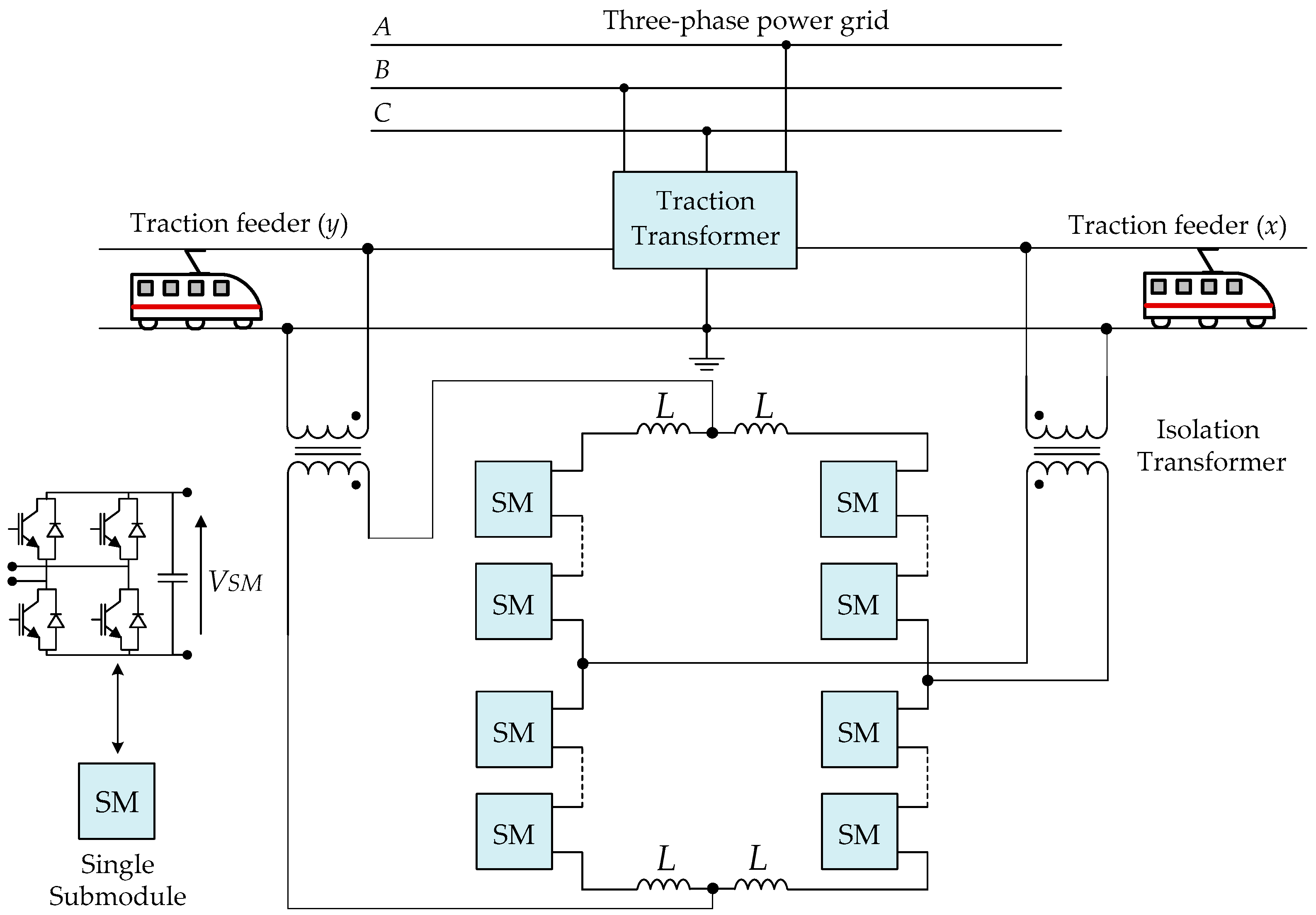
RPC based on indirect AC/DC/AC Modular Multilevel Converter (MMC) and half-bridge submodule (SM) topologies has recently been proposed due to the MMC advantages, such as scalability, lower harmonics production, lower voltage stress, and lower switching losses [
13]. In this context, RPC based on two full-bridge B2B single-phase indirect MMC (HB-MMC4 RPC) and a V/V power transformer is presented in [
29]. In addition, a study of the HB-MMC4 RPC and a Scott power transformer is presented in [
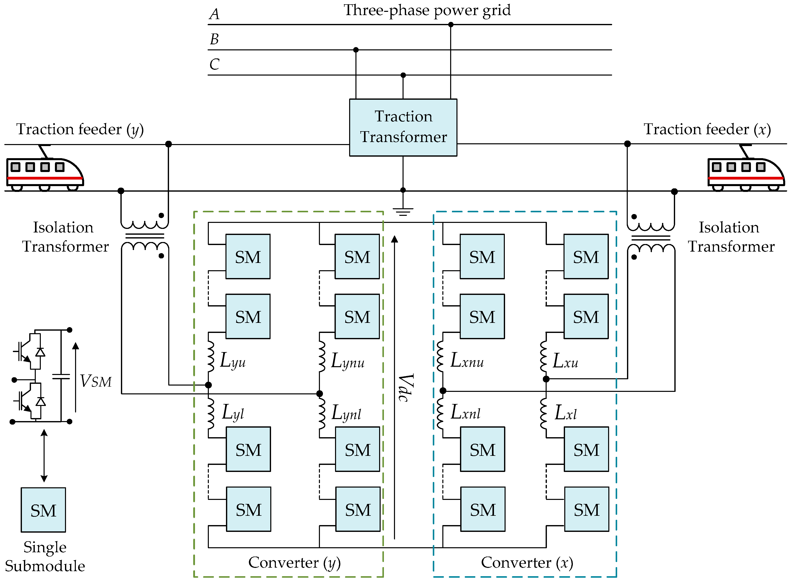
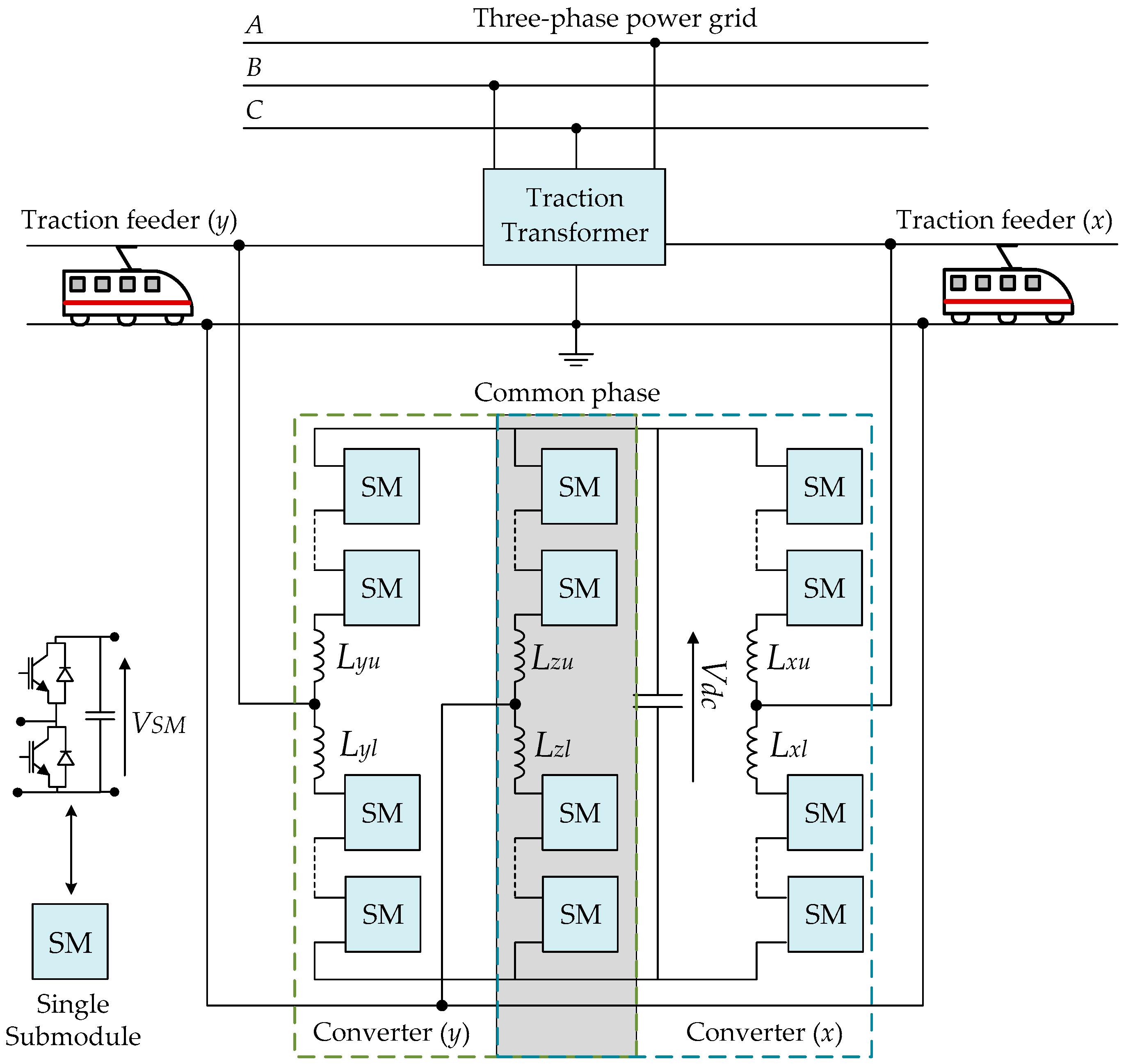
15]. Other studies discuss the RPC based on two-phase three-wire indirect MMC (HB-MMC3 RPC) as a prominent solution in a V/V traction power system due to the lower costs and the high compensation capacity. In this framework, a combination of a hybrid HB-MMC3 RPC and a V/V power transformer is presented in [
30]. In addition, in [
10], the HB-MMC3 RPC in V/V and Scott power transformers is studied. In [
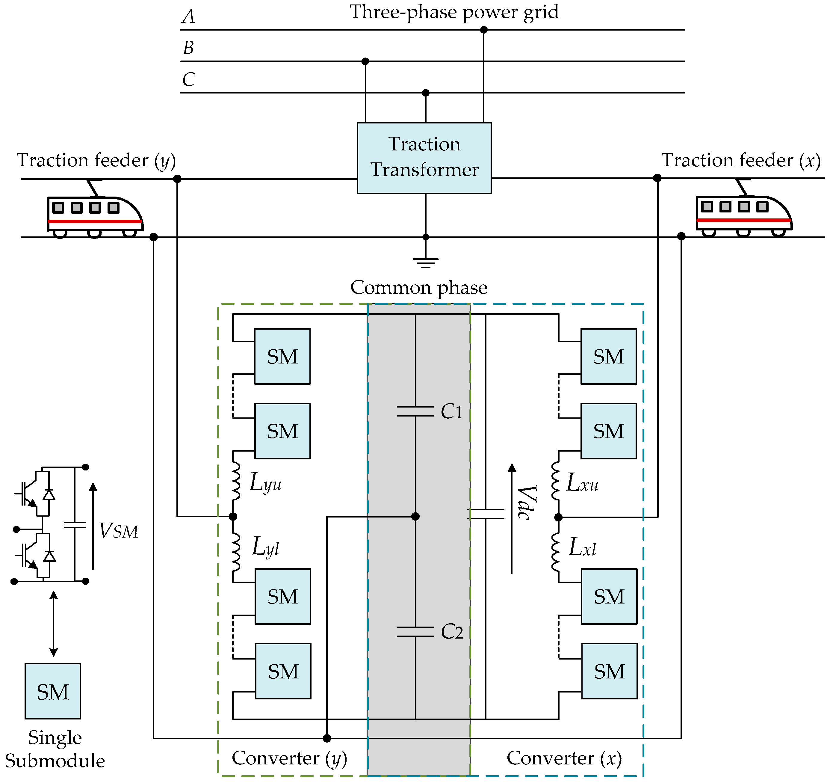
31], the RPC based on the half-bridge indirect MMC (HB-MMC2 RPC) and V/V power transformer is investigated. In [
32], a hybrid HB-MMC2 RPC and a single-phase power transformer is discussed. On the other hand, RPC based on direct AC/AC MMC and full-bridge SM (FB-MMC2 RPC) topology has recently been proposed by researchers. Accordingly, in [
33], the FB-MMC2 RPC in V/V and Scott power transformers is presented, while, in [
34], an evaluation for the RPC based on delta-connected direct AC/AC MMC with full-bridge SM is presented.
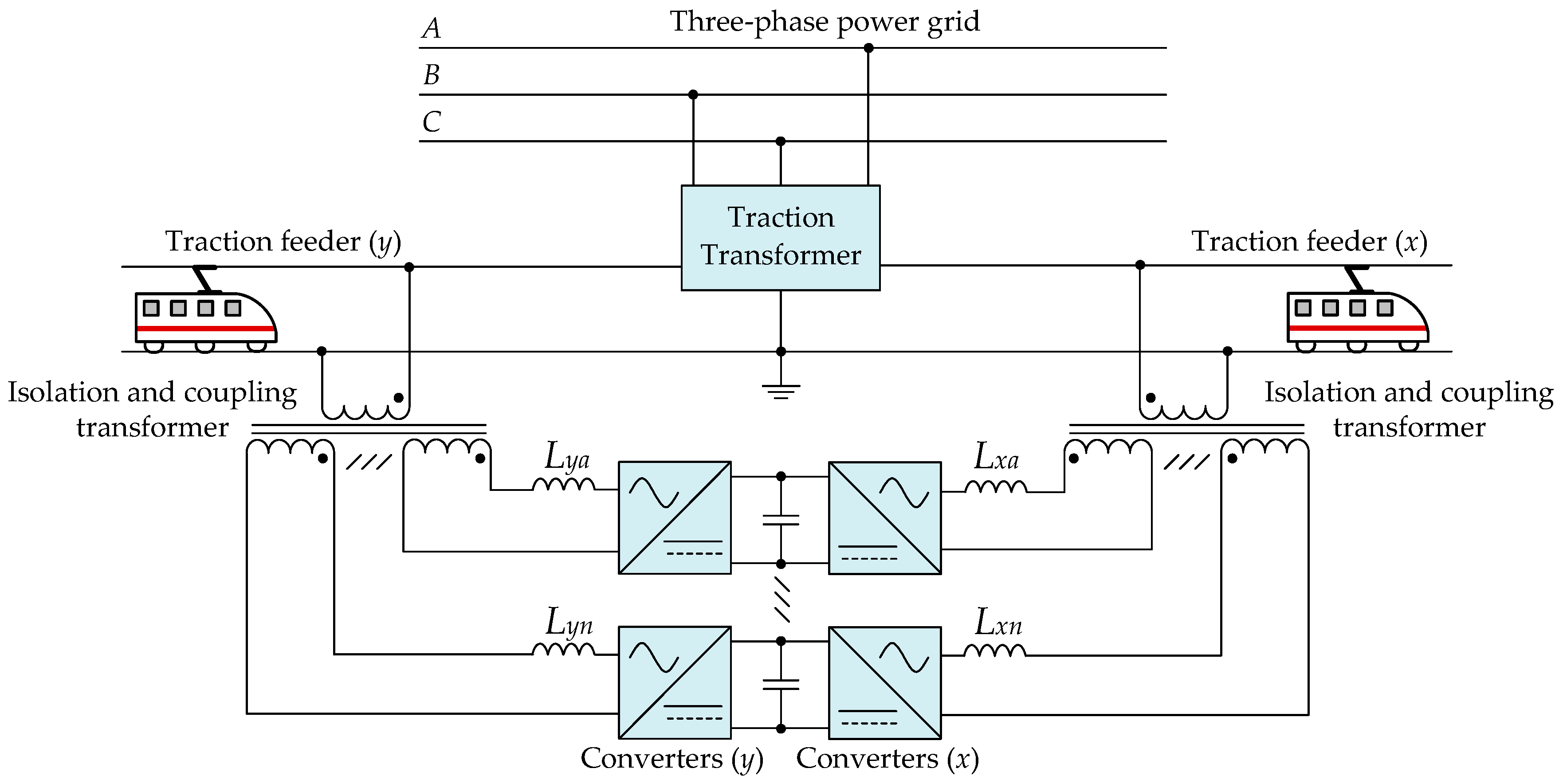
The MMC topology is not the only solution to reduce the voltage and the frequency stress of the RPC switching devices. In this context, modular full-bridge B2B RPC topologies (MRPC) are presented in [
35,
36,
37], in which each RPC module can be treated as an independent FB-RPC. MRPC system for power quality compensation in co-phase traction power supply system is studied in [
37]. The use of MRPC is more common, since a single FB-RPC cannot withstand the high values of currents and voltages. On the other hand, the MRPC solution and its management control strategy with renewable energy access is presented in [
38], showing a better integration of the distributed renewable energy sources along the railway, besides the power quality control of the railway system.
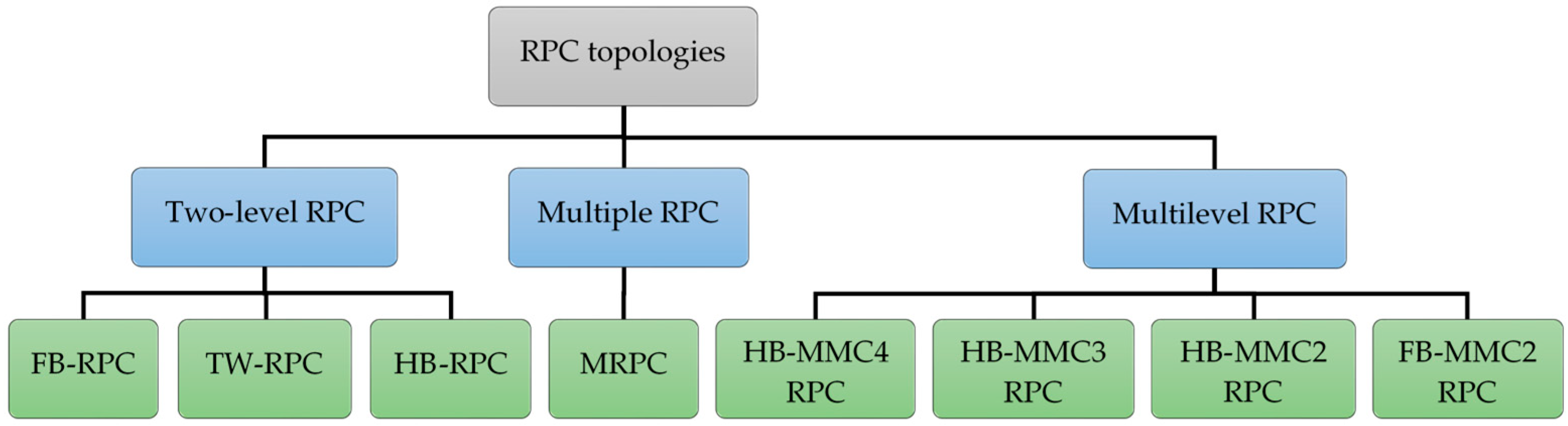
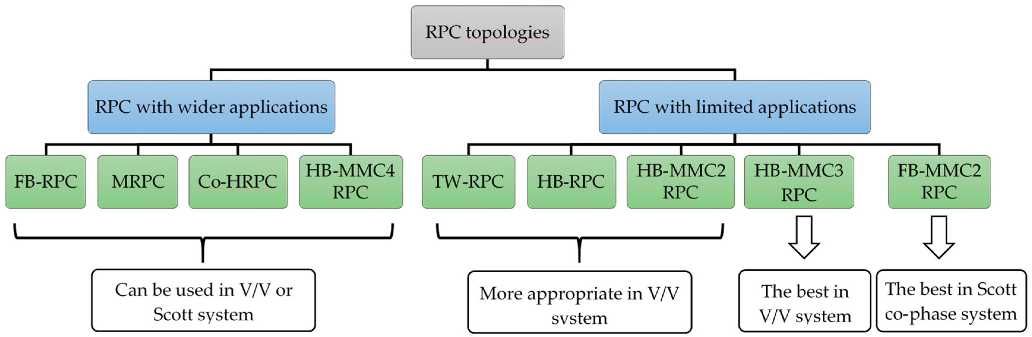
Figure 2 shows a main classification of the RPC topologies. The two-level RPC category consists of a single two-level converter with a limited number of switching devices. The multilevel RPC category, presented in this paper, is mainly based on the MMC, and the multiple RPC category is considered when many two-level RPC modules can be processed independently due to the isolation of the multiple secondary windings transformer. Among these topologies, based on different power converters and traction systems, advantages and disadvantages can be identified, as well as differences between the RPC topologies. Therefore, a key question is: What are the best and most adequate conditions for each topology to operate and when can be effectively utilized? In that respect, no articles in the published studies present a comprehensive review of the RPC topologies, including the RPC operation modes as well. Consequently, the main contribution of this paper is to present a review of the most relevant RPC topologies, presenting a comparative study that includes the main similarities and differences of these topologies. In addition, the RPC operation modes are explained in the paper.
This paper is organized as follows.
Section 2 explains the RPC operation modes.
Section 3 presents a comprehensive study of the most relevant RPC topologies.
Section 4 presents a comparative study between the RPC topologies in the V/V and Scott traction power systems. Finally,
Section 5 summarizes the main conclusions of the paper.
5. Conclusions
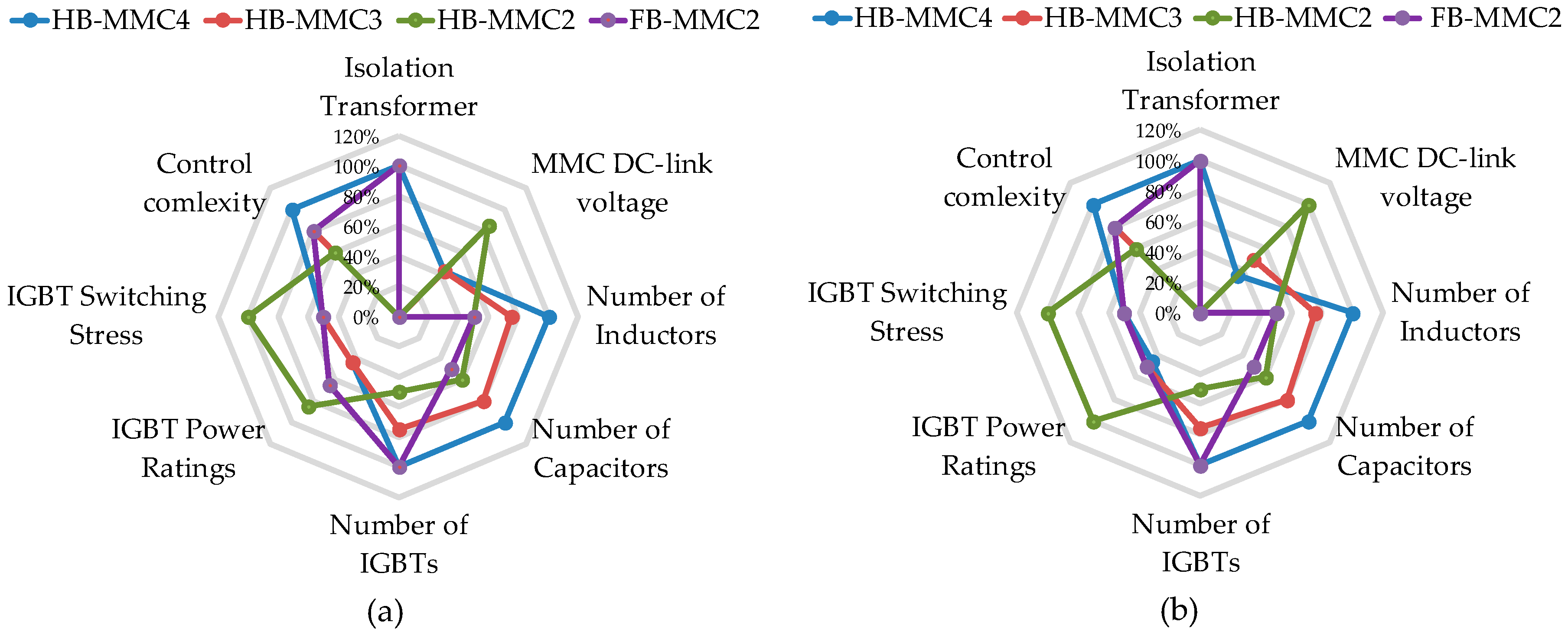
This paper presents the Rail Power Conditioner (RPC) operation modes and nine potential RPC topologies: RPC based on a full-bridge back-to-back two-level converter (FB-RPC); RPC based on a two-phase three-wire converter (TW-RPC); simplified RPC based on a half-bridge two-level converter (HB-RPC); modular RPC (MRPC); hybrid co-phase RPC (co-HRPC); RPC based on a full-bridge indirect modular multilevel converter (HB-MMC4 RPC); RPC based on a two-phase three-wire indirect modular multilevel converter (HB-MMC3 RPC); simplified RPC based on a half-bridge indirect modular multilevel converter (HB-MMC2 RPC); and RPC based on a direct modular multilevel converter (FB-MMC2 RPC). In this paper, after considering a similar voltage level for the multilevel RPC topologies (HB-MMC4 RPC, HB-MMC3 RPC, HB-MMC2 RPC, and FB-MMC2 RPC), the RPC topologies are evaluated and compared in terms of isolation transformer (IT) or coupling transformer (CT) requirements, number of the switching devices, power ratings of the switching devices, number of passive elements required in the RPC system (such as capacitors and inductors), RPC DC-link voltage value, estimated costs of implementation, control complexity, and the required volume for the installation.
As demonstrated, all topologies can achieve power quality improvement after compensating reactive power and overcoming the imbalance of the three-phase currents. The RPC topologies can be classified for wider applications (FB-RPC, MRPC, co-HRPC, and HB-MMC4 RPC) or limited applications (TW-RPC, HB-RPC, HB-MMC3 RPC, HB-MMC2 RPC, and FB-MMC2 RPC), where the RPC for wider applications are adapted to operate in V/V or Scott traction power systems, without high divergence in their characteristics between the V/V and Scott traction power systems. On the other hand, RPC topologies with limited applications are specified and show evident differences between the V/V and Scott traction power systems. These topologies can be more compatible to operate in either the V/V or Scott traction power system. The limited application topologies can give similar or better performances than the topologies with wider applications, also with a lower cost of implementation. The results confirm that the HB-MMC3 RPC is the best topology in the V/V traction power system, since it provides a similar performance of the HB-MMC4 RPC, but with a lower quantity of hardware devices, lower control complexity, and without the need for ITs, which means lower costs of implementation. On the other hand, since the reactive power compensation is not a vital factor in the Scott traction power system, the FB-MMC2 RPC is the best topology to be used in the Scott traction power system. However, ITs are required to interface between the FB-MMC2 RPC and the traction power grid, which highly increases the implementation costs of the FB-MMC2 RPC. Nevertheless, using the FB-MMC2 RPC in the co-phase Scott traction power systems helps to overcome this disadvantage, besides reducing the FB-MMC2 RPC overall costs.

 ,
, 


