Article

Method for Assessing Heat Loss in A District Heating Network with A Focus on the State of Insulation and Actual Demand for Useful Energy

1
Omsk State Transport University (OSTU), 35 Marx av., 644046 Omsk, Russia
2
Utilitas OÜ, Punane 36, 13619 Tallinn, Estonia
3
Department of Energy Technology, Tallinn University of Technology, Ehitajate tee 5, 19086 Tallinn, Estonia
*
Author to whom correspondence should be addressed.
Submission received: 29 July 2020 / Revised: 17 August 2020 / Accepted: 19 August 2020 / Published: 1 September 2020
(This article belongs to the Special Issue Recent Studies in District Heating and Cooling Systems)

Abstract

:
The goal of this paper was to evaluate heat loss and the demand of district heating (DH) in the context of the fourth generation DH concept using a data-driven approach. The heat loss profile was calculated with GIS Zulu© (software (8.0.0.7539, Politerm, LLC, St.Petersburg, Russia) using eight various states of insulation, detailed information on thermal conductivity, internal heat transfer coefficient, and geometry of the concrete trench. There is a strong correlation between the heat sold and the average annual outdoor temperatures. The outstanding episodes are extremely rare, and the difference in the overall pattern is elusive. The results of the annual heat production and annual heat loss analyses were compared using three different estimation methods. The new method was the only one that showed a positive effect after the complete modernization of thermal insulation. The actual proportion of heat loss is much higher at 16%, while the actual heat delivery is less than anticipated at 85–86% only. The trend of the normative approach is correct but cannot determine changes in network heat loss due to aging. The method focuses on the effects of the state of insulation and actual supply temperature levels. The transition to smart energy systems includes strategic and progressive energy planning, as well as new pricing rules and tariffs. Thus, the method presented is the first step in the transition towards the fourth generation DH networks.

1. Introduction

1.1. Prior Research

In existing district heating (DH) networks, heat loss can be reduced by lowering operating temperatures, that is, supply and return temperatures. If they are low enough (supply temperature of 60 °C and below), the DH becomes the so-called low-temperature DH, which is part of the fourth generation DH concept. Lund’s et al. view on the role of smart energy systems and fourth generation district heating is presented in [1], its status is discussed by Lund et al. in Ref. [2]. Wirtz et al. [3] discern even the fifth generation of DH following the fourth one. The creation of a group substation for connecting low-temperature DH subnetworks to an urban high-temperature network was described as a part of the energy and environmental modeling [4] and within Volkova’s methodology for evaluating the transition process dynamics towards fourth generation DH networks [5]. The changes in the cross-section geometry of the thermal insulation of the DH network from circular to egg-shaped are under research in Ref. [6]. In addition, it is expected that real-time minimization of the DH operational characteristics will help to reduce heat loss and required pump power. The real-time minimization can be classified in the following categories: (1) associated with demand side measures (DSM, e.g., made by Tunzi et al. [7]), (2) applicable for both district heating and cooling networks (e.g., [8]), or simplified for the supply temperature at a DH plant only [9]. The research topic is also of great importance for cold regions. This study provides a good opportunity for a deeper analysis of heat loss in DH. Heat loss as one of the main criteria for network design or as an evaluation factor was discussed to design pipes for low-energy DH [10] as the evaluation factor with respect to network geometry [11] and to reveal the cost of heat ultra–low-temperature DH networks with booster heat pumps [12], but, to the best of our knowledge, all the methods presented are not applicable for a long-term assessment of an entire DH network. Turski et al. [13], Hammer et al. [14], Chicherin [15], and Noussan et al. [16] presented similar papers analyzing heat loss, curves, and demand fluctuations.

1.2. Background

This study is focused on low-temperature DH, which can achieve high efficiency when operating at low temperatures. Conversion to low temperature is becoming essential for technology to continue playing its part in the future. A closer look at the wasteful use of heat in DH networks highlights the importance of low-temperature networks, as well as heat loss reduction, bringing us to the fourth generation DH systems. However, in Russia, DH systems have historically consisted of large industrial facilities owned by the state. In Russia, the so-called second generation (1930–1980) DH (2GDH) systems were used, where heat was generated by centralized plants that supplied highly pressurized hot water (over 100 °C) through pipes laid in concrete ducts. Thermal energy produced at a DH plant located outside the city is traditionally transported via a branched network (150 °C in the supply line, and 70 °C in return) to a group substation and then finally to the consumer with 95/70 °C hot water and 60 °C domestic hot water (DHW).
The main goal for the 2GDH was to achieve fuel savings and greater comfort with combined heat-and-power (CHP) [17]. In cases where government policies and planning initiatives were introduced, many benefits were gained, although there were also some barriers. State policy provided even single-family houses with low linear heat density and long heat distribution lines with an opportunity to connect to the DH network; however, the implementation of such a connection would come across additional barriers, such as significant heat loss and poor quality service. In Russia, heat demand density may be as low as 0.5 MW/km2 if areas with poor single-family houses are taken into account [18]. However, during the Soviet era, even these areas were connected to the DH network. The situation is exacerbated by insulation theft in areas where pipes are publicly accessible, and hydraulic balancing issues.
The abovementioned factors contributed to the fact that, in Russia, heat is currently supplied by 2GDH systems. Due to aging, the systems are currently expected to operate at a limited supply temperature of 110–115 °C, which is acceptable unless peak load conditions arise.
There are various obstacles hindering the transition of the existing DH towards the fourth generation, including barriers to low heat loss in networks, barriers to the use of renewable (non-fuel) energy, and barriers to smart metering [5]. Market-related barriers and lack of data privacy also hamper the transition towards low-temperature smart DH networks. Finally, in the current economic and legal environment, potential developers and/or existing consumers have no reason to be interested in implementing advanced technology in underdeveloped areas. The specific legal situation is that there are no government-supported approaches to planning the development of heat supply facilities and no requirements for a comprehensive analysis of all available options in order to choose the type and capacity of the DH system, which leads to a gas heat-only boiler plant as a preferred option. In this case, existing economic and other related issues, such as outdated infrastructure, utility bill arrears, unclear efficiency and reliability indicators, unresolved zoning by type of heat supply, justification of the optimal dimension of the DH system (i.e., heat supply radius), and concentration of heat source capacities must be solved as well. To sum up, it is evident that there is a long way to go until DH systems can fully transition into the 4GDH. Thus, it is difficult to implement in developing countries such as Russia. This paper addresses the challenge.
The model presented in the paper is useful for countries that have similar average conditions to those of DH systems in Eastern and/or Central Europe. The normative approach can also be used for similar types of the 2GDH system (in terms of network heat loss, temperature differences at substations, heat loss from hot water tanks, back pressure turbines at CHP plants, boiler efficiency, etc.), for example, in Serbia [19]. Moreover, in such countries, there are no schemes that provide an economic incentive for consumers to invest in improving the space heating (SH) control system, as they are charged a fixed tariff for heat consumption. Although no particular experience can be directly extrapolated, this paper can still provide useful methodology and recommendations for other developing countries.

1.3. Features Related to the 2GDH in Scientific Literature

At least two publications addressed the issues of wear and tear of high-temperature systems—Čulig-Tokić et al.’s research describing Croatia [20] and Zhang et al.’s research describing China [21]. The impact of climate change and construction (excluding network renovation) on the annual heat demand and linear heat density (heat demand per meter of network trench length) was described in [22,23]. The ownership of the various components of the DH system is of great importance when it comes to losses and repairs, because the ownership pays for them. On the one hand, in Russian practice, regardless of which technical solution is chosen, DH network pipelines belong to the city’s DH network operator, while the CHP or heating plant typically belongs to another business owner. Heat delivery is usually controlled by the same DH network operator or even by a third party, which creates an obstacle to successful investment. On the other hand, this could have been different if the entire DH system had been renovated. For example, in Europe, DH service companies tend to own large heat generation facilities that can profit from the production of heat and power. This is the case in major cities in Estonia.
Several researchers [24,25,26] have focused on active monitoring to facilitate the operation of conventional DH systems and to manipulate heat load and delivery. Heat delivery is highly dependent on interruption [27,28]. For this purpose, concrete anchors should be used instead of steel ones to increase the rigidity of a DH network [29].

1.4. Local Specificities

Since DH substations in heated buildings built during the Soviet era rarely include heat meters, the tariff for the end-user consists of both the cost of thermal energy loss and the amount of heat consumed. Residents of multi-story buildings also pay building maintenance bills, which include heat loss in the final sections of the DH network. Moreover, in accordance with Russian law, legal entities pay for these losses directly, regardless of whether they have heat meters or not, unlike the residential sector. To sum up, all consumers are forced to pay for distribution losses. This is also true for China, where the two main tasks nowadays are creating a heat metering and billing mechanism based on actual consumption and improving building energy efficiency, as Zhang et al. highlight [21]. This has prevented researchers from analyzing actual heat loss, as this process continues throughout the country. Historically, in Russia (the USSR) or China, heat loss was never considered. This was because before only CHP generation was valued, regardless of heat supply methods. Only temperature and flow rate data at the plant outlets were collected, which were then used to estimate heat loss.
Therefore, the normative approach is used for the entire DH system in Russia and, in particular, in Omsk. This means that heat loss values are precompiled using the area’s climate data and then adjusted for the actual supply temperature range of 70–110 °C, although the 150/70 control curve is still declared. The same with the work of Von Rhein et al. [30], based on the calculated temperature of the simulation, the amount of heat introduced into the network is linearly interpolated from the lookup table. For this purpose, the traditional input data includes average variables, such as the overall heat transfer coefficient of the network, pipe dimensions and length, as well as supply, return, and outdoor temperatures. Volkova et al. [31] also use this evaluation method.
This evaluation method and the natural monopoly of DH networks usually results in end-user being locked in the agreement with the heat supplier without being able to appeal for tariff changes, as is the case in liberalized electricity and gas markets. This is typical of countries such as Estonia, Croatia, Poland, China, and Russia where the heating market never existed.
Due to distribution inefficiency, heating rates may increase over several years. Rising heating costs can lead to dissatisfaction and potential disconnection from the distribution system, raising the question of its feasibility [32]. Moreover, low transparency of heat prices can jeopardize consumer confidence and trust in the DH technology itself, as is the case in Eastern Europe and the Commonwealth of Independent States (CIS). Therefore, although standard demand profiles are still used even in Europe [25], in 2020, heat loss evaluation could be advanced with a more detailed consumption pattern analysis based on real measurements using a data-driven approach as described below.

1.5. Aim

The goal of this paper was to evaluate two aspects of DH in the context of the fourth generation DH concept using a data-driven approach based on the actual demand for useful energy and methods of calculating heat loss, including observational error, specifics of local enterprises, and international experience. Taking a closer look at the wasteful use of heat in DH networks is the first step towards 4GDH systems. The transformation also requires improvements to be made in the operation of DH networks, as well as an overall increase in efficiency. Heat and water loss (leaks), accident costs, excessive consumption of fossil fuel, increasing heat supply tariffs and greenhouse gas (GHG) emissions inevitably limit the efficiency of the DH system. Therefore, the main idea is that the key to discovering the future of DH is sustainable energy production and distribution in particular.

2. Materials and Methods

The current so-called normative method is traditional, since it is manually applicable and does not require a model of the DH system. The hourly heat loss under the annual average operating conditions of the heat network and in accordance with heat loss standards is determined separately for underground and above-ground piping, according to the following formulas.
- For underground installation with the supply and return pipelines combined:
Q a v . a = ( q L β ) ;
- For above-ground installation, separately for the supply and return lines:
Q s a v . a = ( q s L β ) ,
Q r a v . a = ( q r L β ) ,
where q, qs, and qr are the specific (per meter of length) hourly heat loss values determined by the heat loss codes for each pipe dimension under the annual average operating conditions of the heating network; L—length of the pipe of each dimension in the DH network, in a two-pipe calculation for underground installation and for the supply (return) line for above-ground installation, m; β—local heat loss factor, which takes into account the heat loss created by fittings, compensators, and supports. The local heat loss factor β is 1.2 for a pipe in a concrete trench and above-ground installation, for pipes up to 150 mm in dimension; and β is 1.15 for pipes of 150 mm or more, as well as for all pipe dimensions installed underground [33].
The values of a specific hourly heat loss are determined according to Russian policy [33] on the heat loss in DH networks in accordance with tables such as Table 1.
Although there are methods used to calculate thermal resistance and heat loss for certain lengths of DH networks, e.g., Wang’s et al. research [34], they are not applicable for a long-term assessment of an entire DH network. We suggest using a method that can take into account various factors (weather, supply temperature, state of insulation and its moisture content, etc.), but is still based on the overall heat loss assessment technique defined as the ratio of heat flux to thermal resistance. According to the base textbook on heat transfer (e.g., Incropera [35]), it should look as follows:
q l o s s = U A o ( τ T s o i l ) ,
U = 1 R ,
A o = d o Δ x .
The calculation begins from determining the thermal resistance of the network.
R = R c o n v . i + R 1 + R 2 + R 3 + R s o i l ,
where
R c o n v . i = 1 A i h i ,   A i = d i Δ x ,   R 1 = ln r 2 r i 2 π k 1 Δ x ,   R 2 = ln r 3 r 2 2 π k 2 Δ x ,   R 3 = ln r o r 3 2 π k 3 Δ x ,   R s o i l = 1 S k s o i l ,   S = 2 A cos 2 Z d o .
Δx is the unit of pipe length (1 m), τ is the daily average supply/return temperature; r1 is the inner radius of the pipe, r2 is the radius of the insulation layer, r3 is the radius of the casing, and r4 is the external radius of the pipe; k1, k2, and k3 are the thermal conductivities of steel, insulation, casing, and soil, W/m·K, ksoil is the thermal conductivity of the soil around the pipe, W/m·K, Z is the depth in which pipeline is buried, m, hi is the internal heat transfer coefficient; referring to Incropera’s handbook [35], this means
h i = k 1 d i 0.023 Re 0.8 Pr 0.3 .
In traditional equations (e.g., those presented by Wang et al. [34]), a power factor of 0.4 at the Prandtl number corresponds to the medium that is heated. In DH, the medium is cooled due to heat lost to the environment in which case the power factor at Pr must be 0.3.
By substituting formulas for Rconv,i, R1,P R2, R3, and Rsoil into Equation (7) and indicating the total thermal resistance to the outer surface of pipe casing with Equation (5), UAo, which is the overall heat transfer coefficient relative to the outer surface of pipe casing, is determined.
Arabkoohsar and Alsagri [36] provide equations valid for the entire range of flow velocity in typical DH systems, 0.05–2 m/s, a wide temperature range (20–120 °C) for any of the lines and for any pipe dimensions with temperatures, dimensions, and numerical factors only.
Relative heat production, P ¯ , is expressed as follows:
P ¯ = P c P d ,
where Pc is current heat load, MW; Pd is design heat load, MW.
Then, the correlation C between the mean behavior of any reference group and its target can be determined using standard formulas.
They are compared against the adequacy criterion of 0, −1, and 1. When C is approaching ±1, this indicates that the processed parameters, such as the mean or standard deviation of the target set (average annual outdoor temperature) and/or most members of its reference group (heat sold from the heating plant), changed equally. Similarly, when C is approaching 0, this indicates that the target and its reference group do not behave similarly over time [37].
The heat loss profile was calculated with the geographic information system (GIS) Zulu© 7.0 software [38] using a set of 15 layers, 8 various states of insulation, as well as detailed information on thermal conductivity, internal heat transfer coefficient, and geometry of the concrete trench, all determined and input in accordance with the National Building Code.
ZuluThermo© (8.0.0.7539, Politerm, LLC, St. Petersburg, Russia) is a simulation program built into the GIS Zulu© for DH networks, with an option to also simulate water, cooling, and gas networks. Figure 1 provides insight into the number of heat generation facilities, consumers, and the length of the distribution network.
Areas with a maximum heat loss (usually due to insulation theft if above-ground and next to a DH plant or due to being underwater in segments that were flooded due to infrastructure failures) are marked in red. Blue indicates areas with low heat loss values or within an acceptable deviation range. The first number is the DH plant’s design electrical power (if any), the second is its heat production. The software can calculate both values by sequentially entering the actual supply, return, and outdoor temperatures for each day, and determine steady-state flow relationships in any number of meshed utility networks for Newtonian fluids in filled pipes. ZuluThermo© also offers a user-friendly interface that may come in handy for taking wear rates into account and interacting with external software. Meanwhile, Teleszewski et al. [39] developed another kind of model in which the DHW pipes have been added to the common with the supply and return pipes round thermal insulation, and to determine heat losses, a simplified two-dimensional model of conductive heat transfer was created.
Omsk, Russia, where the initial DH network temperature requirements of 150/70 °C are not met, was taken as the case study for the purpose of this research. The design outdoor temperature is extreme at −37 °C. The design conditions in Russia are based on the indoor design temperature of 20 °C, while the design outdoor temperature varies greatly according to SP 131.13330.2012 “Building Climatology” [40], an updated version of the Soviet heat and energy code SNIP II-A.6-72 “Construction, climatology and geophysics” that was approved in 1972. The conditions are much more severe than those provided by the American Society of Heating, Refrigerating and Air-Conditioning Engineers (ASHRAE) Standard and the ASHRAE Climatic Design Conditions [41]. For instance, in the section of Annual Heating and Humidification Design Conditions, the ASHRAE Climatic Design Conditions [41] provides dry-bulb temperature corresponding to 99.0% annual cumulative frequency of occurrence (cold conditions) accounting for −29.9 °C. According to the design conditions in Denmark described by Østergaard and Svendsen [42], the outdoor design temperature there is only −12 °C, which leads to significantly more moderate operating conditions. Omsk’s DH network is an old and extra worn-out network with 2nd generation technology, which includes large losses and a higher proportion of fossil fuels: coal, natural gas, and heavy oil. Despite this, 76.33 °C and 45.94 °C of the weighted average supply and return temperatures [15] are close to those (73.71 °C and 40.52 °C) in Danish systems [43]. Relatively low average values, firstly, are due to the fact that the 150/70 °C control curve is only claimed but never actually met, as the 115/70 °C control curve is much closer to real life. Secondly, −37 °C is just the design outdoor temperature, all recent winters were much warmer with an average temperature of −20 to −15 °C. This may suggest that the current design outdoor temperature is incorrect; this idea is supported below. All recorded outdoor, supply, and return temperatures are detailed and thoroughly examined in Chicherin’s research [15]. Retrofitting of the distribution system that started in 2016 should make it possible to operate the system at high temperatures, as was originally designed [44].
The data on network operation was obtained from the literature sources available and from the database of the Omsk DH company (e.g., [45]), including supply and return temperatures, which were previously described in Chicherin’s research [15]. It also shows the variation in the amount of (a) heat sold from the heating plant (heat produced) and (b) heat supplied to consumers; projected, or so-called normative heat loss, and actual heat loss calculated as the difference between (a) and (b) during 2007–2017. Each time period was supplemented with dry-bulb outdoor temperatures. Reference weather data (.epw weather files) from the local meteorological center were used. The file consisted of daily values of 25 weather parameters, including average daily external and wet-bulb temperatures, humidity, solar radiation levels, as well as wind speed and direction. Five variables (average daily temperatures, max/min temperatures, wind speed, and soil temperature) were taken into account. Average monthly and annual outdoor temperatures were determined using average daily measurements, accurate to within 0.1 °C. The estimated annual average outdoor temperature dataset is fairly representative, because, according to results obtained by Turski et al. [13], the global trend of daily outdoor temperatures during 1953–2016 also indicates increasing average outdoor temperature.
Actual numbers represent the difference between heat produced and heat consumed for each month and are indicated by the black bar below. Monthly values were obtained for the former as the sum of daily energy production values (in MWh) of the five largest DH plants (see Figure 1), and for the latter as the sum of heat billed to consumers per day. The heat produced was calculated by multiplying the difference between network supply and return temperatures by the supply water flow rate measured at DH plant outlets. NR Series sheathed resistance thermometers were used as temperature sensors. They are sealed and filled with an inorganic powder insulator (high purity magnesium oxide) inside a metal protective tube (sheath) with a platinum resistance element. They were standardized classes in, for example, DIN 43760:1980-10 [46] that was withdrawn in 1987 and not defined by the later IEC 60751 standard [47] or its German counterpart DIN EN 60751. The tolerance of these sensors corresponds with a class B accuracy, but the fixed portion of the error (e.g., 0.3 °C) is divided by a given number (3 or 10). The accuracy (tolerance) values of these particular sensors are ±0.1 °C + 0.5%.
Ultrasonic devices were installed at plant outlets to measure the flow rate. The accuracy of a flow meter can be specified in two ways: as a percentage of full scale (FS) or as a percentage of reading (RD, also referred to as percentage of rate). Flow meters with accuracy expressed in FS with a fixed error band across the flow range of the meter are installed. For example, the flow meter installed at the CHP plant (CHPP) No. 5 has a 1% FS accuracy with a range of 10 gallon per minute (GPM)–100 GPM and an error band ±1% of 100 GPM, which is equal to ±1 GPM. Since the accuracy of the flow meter is ±1 GPM throughout the flow range, this type of meter is most accurate at full scale, 100 GPM, and becomes less accurate as the flow decreases. When the meter is at a measuring flow of 50 GPM or 50% FS, the actual flow will be within ±1 GPM, or anywhere from 49 GPM–51 GPM. At the bottom end of the flow range, or 10 GPM, the accuracy is ±10%, 1/10 = 10%.

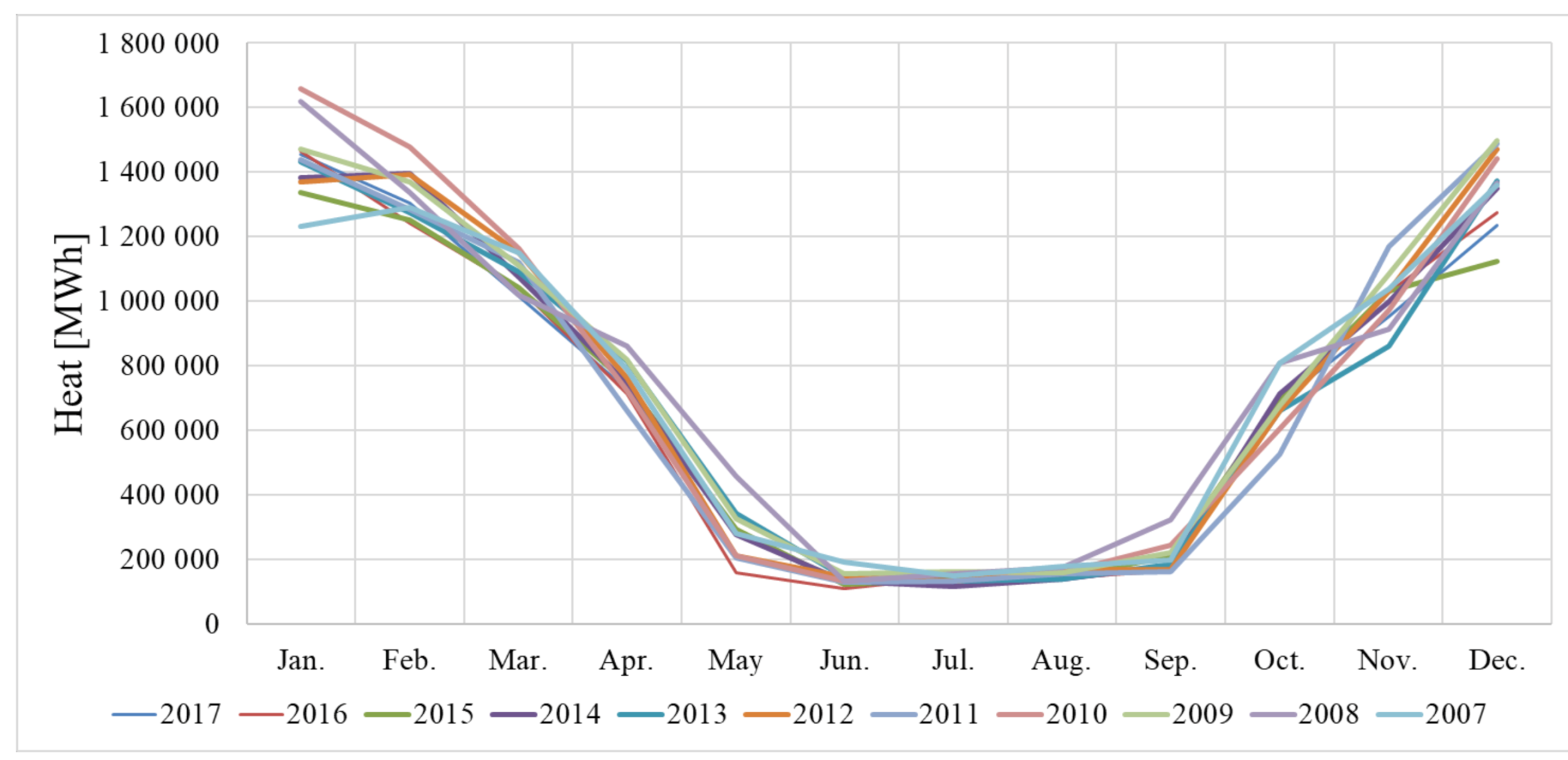
3. Results and Discussion

The correlation between the amount of heat sold from a heating plant and average annual outdoor temperatures is shown in Figure 2.
Like a substation [48], the entire network can be characterized by its heat demand (which is a time series that can be predicted to satisfactory accuracy based on weather forecasts and time patterns) and its temperature characteristics. Based on the official climatic data of Omsk, and adjusting the data according to the typical meteorological year, the annual frequency of outdoor temperature was determined as ranging from 1.42 °C to 3.74 °C throughout the decade. Figure 2 shows a steep upward curve, indicating a strong warming trend, whereas the flat downward curve indicates the coincidence of a low load and less intense heat consumption. As in the Meesenburg et al.’s research [43], to calculate the relative annual heat loss, an adjustment for the assumed network temperatures for low-temperature DH and ultra-low-temperature DH was made to determine the correlation presented in this paper. The result is −0.76, which means that the strong correlation matches up well with Meesenburg et al.’s study [43].
The trend obtained as the average annual increase in outdoor temperature over 10 years is 0.149 °C/season. During 1953–2016, Turski et al. [13] reported the increase to be about 0.064 °C/season. Figure 3 depicts the variations of actual demand for useful energy in different periods of time.
The source is DH plant’s heat meter data (supply and return temperatures and flow rate). This means that all new consumers and the effects of network/building renovation measures are tracked along with other deviations. The relatively close operating states in the lower part of Figure 3 at the supply temperature of 70 °C indicate that space heating is switched off and the supply temperature is no longer affected by weather changes. In summer, when there is no need for space heating, only the DHW load exists. It can be seen that during the periods of a low load, for example, in summer, autumn, or spring, almost 3.2 times less heat is sold than in winter. Outstanding episodes are extremely rare, and the difference in the overall pattern (excluding December and January) is elusive. This proves that for 10 years practically no new consumers appeared and no network/building renovation measures were undertaken, which significantly affected the behavior of the entire network. Moreover, this proves that most of the changes that are caused by weather patterns are random. Thus, to estimate heat loss, it is sufficient to consider only a 10-year period of heat output.
For the heat delivery points located higher than others (e.g., January 2008 and 2016; May and September 2008), the average monthly outdoor temperature was much lower, which explains why the DH network requires a greater proportion of heat demand than usual. During warmer periods (January 2007; January and December 2015; May 2016), consumers required 15–25% less heat than the average in most neighborhoods. The greatest difference (up to 38%) was observed in December and January, the coldest months in Omsk. This can be explained by a wider supply temperature variation, abrupt flow changes (since the 150/70 °C control curve is not achieved), and even by the fact that during these particularly high load periods, in the event of a major failure (accident), the network’s unavailability is relatively long, compared to autumn or spring. Thus, Figure 4 is chosen to show the average cost savings for all these months for the heating plant and the distribution company.
Actual numbers (the difference between the heat produced and heat consumed) are indicated by the black bar, the numbers calculated using the new method are indicated by red characters, and blue characters for the current method. The dotted line represents a regression function indicating the global warming trend. The upper part of Figure 4 more or less shows the boundary between correct and incorrect calculations for various methods, as further detailed in Table 1. Based on the actual numbers (black bar), it can be statistically assumed that the traditional method works great at an average monthly outdoor temperature of −18 °C and higher. Particularly useful in visualizing the effect are cases of temperatures below −15 °C. Over the past 10 years, there have been no temperatures below −20 °C that lasted 5+ days, which supports the idea that the current design outdoor temperature is incorrect. There were 11 cases of average monthly outdoor temperature below −15 °C, and four cases below −20 °C over the 10 heating seasons. Such episodes occur only once every five heating seasons but contribute over to one million MWh of heat loss, which is not taken into account. The points of December 2016 and January 2017 show a positive effect after the complete modernization of the thermal insulation in the summer of 2016, although the traditional method shows no modernization-related changes. Conversely, one of the points in this network operating diagram indicates that the heat loss is nearly 0, which is an error.
The trend of the normative approach is correct: warmer weather leads to less heat loss; however, this method does not reflect changes associated with aging, and, therefore, cannot be used to determine changes in network heat loss.
This differs from using DH in Denmark [49] or Sweden [50], but, as shown in Table 2, the actual proportion of heat loss is larger than in the Scandinavian countries, reaching 16%. The reason is linear heat demand density (LHDD) as detailed in Meesenburg et al.’s research [43].
The values in the ‘Charged to consumers’ column are obtained as the sum of the amount of heat billed to the consumers and divided by the actual annual heat production (see Figure 3). In relation to the total heat demand, the actual demand for useful energy varies from 85% to 91% for instant systems and is well suited to the billing practice. Moreover, when the outdoor temperature is relatively low, such as in 2010, [14] 2011, or 2016 (excluding 2014, see Figure 2), the actual heat supply is lower and amounts to only 85–86%. This can be explained by the fact that during these high load periods, network failures are more likely. Thus, the DH network is cooled more than during a warm year, and, therefore, the proportion of heat supplied to consumers is lower. The temperature difference is also greater, which results in greater heat loss. In Beijing, China, 0.30 GJ per square meter is required to meet annual heat demand, while 0.45 GJ of heat must be produced to provide an indoor temperature of at least 18 °C in winter, as Zhang et al. describe [21].
Distribution losses range from 0% to 5%, reaching the maximum in 2016. The fundamental difference between the new and current methods is that the following aspects are taken into account: (1) the influence of insulation defects and moisture content on normal operating mode, (2) intermittent operation, and (3) ground temperature during the heating season, depending on the weather. The view is that (1) and (2) are mainly responsible for additional network heat loss according to the new methodology and add about 0–5% of the difference in network heat loss evaluation, and (3) is probably responsible for the extra 0–2% of the difference in the evaluation.
From the heat supplier’s point of view, the new method has both advantages and disadvantages. On the one hand, compared with the old method, the new one proves the need for investments in the DH infrastructure and a possible positive effect when invested.
This allows the company to preview the potential outcome and decide whether to continue or not. Since the cost of revising the planned DH network is high, it is vital to demonstrate the potential positive impact to the potential investor relative to the total project cost. The proposed model can quantitatively demonstrate this as a percentage (see Table 2) or in MWhs (see Figure 4, ‘over a million MWh’). The small time invested in this new method can help prevent larger losses in the future.
Moreover, after installing new pipes to replace or expand the existing system, the network losses can be reduced by further increasing the thickness of insulation, by optimizing/minimizing pipe dimension, and through an alternative pipe layout. On the other hand, DH companies will no longer be able to force consumers to pay for excessive distribution heat losses.
There is an unexpectedly significant increase in network losses [14] compared to the normative method (Figure 4) and confirmed by actual data. This is due to the fact that in the USSR, where this method was established, (1) DH lines characterized by wear and tear and moisture insulation were not widespread and (2) there was almost no excessive flow through certain sections of the DH network due to the hydraulic balancing issues. The latter has almost been resolved because ZuluThermo© provided a very realistic demonstration of flows through consumer substations, and excess flows were limited by controlling heat demand. However, the difference also results from (3) the flex temp operating mode (110/70 °C control curve instead of the claimed 150/70 °C), which is finally taken into account with the new method.
Culig-Tokic et al. [20] divided heat loss into specific heat loss due to water loss and specific heat loss due to heat transfer. They indicated that the latter differs from the annual average heat loss, since the supply temperature that is usually used in the calculation is from one of the coldest days. There was no such a problem in the present paper, because daily average supply and return temperatures were input.

4. Conclusions

The use of energy resources in regular urban areas was examined using actual measurements and simulation analysis. A real city with over 10,000 residential, office, and commercial buildings supplied by a worn-out high-temperature network was used as the case study. The results of the annual heat production and annual heat loss analyses were compared using three different estimation methods: (1) traditional normative method, (2) novel method, and (3) calculated as the difference between heat produced and heat consumed. The proposed method focuses on the effects of the state of insulation and actual supply temperature levels, and it has been validated by actual measurements with an error of up to 5%.
The transition to the new assessment method and smart energy systems requires innovative planning guides, support tools, policies facilitating the transformation, along with changes in the cost of energy evaluation practices. These include strategic and progressive energy planning, taking into account legislation and urban development, creating heat maps to aid in the planning process, and ideas for new pricing rules and tariffs. Thus, the new method is the first step in the transition towards the fourth generation DH networks, featuring transparent methods, heat metering, access to information, and fair prices [51].
Based on the determined temperatures, and provided that measures increasing the thermal performance level in buildings are implemented, the paper concludes with a description of the new proposed direction for the Russian national code. This includes design outdoor temperatures comparable to those in the current version of the ASHRAE Standard instead of the extremely low design outdoor temperatures that have been in effect since 1972, which lead to excessively large networks.
Several aspects of this study can be improved and expanded upon. An annual overview in the case of a DH network does not provide an accurate description of the actual DH system. Dynamics, such as heat transfer delays, may be added in the future to allow simulating the dynamic operation of the DH network and to represent the use of an advanced technology, such as thermal energy storage facilities and heat pumps integrated into the DH system. In addition, once mapping is added, the proposed approach can provide insight into and the ability to spatially determine and quantify local demands and resources to correctly assess the potential of both DH and cooling.
However, once all consumers are equipped with properly functioning heat meters capable of providing data to utilities and service companies using remote reading technology, there is no more strategic need for indirect evaluations. Despite the uncertainties and limitations of the study, it should be pointed out that in addition to the experimental validation, the results are in line with other papers on similar topics [13,14,15,16].

Author Contributions

Conceptualization, S.C. and V.M.; methodology, S.C., A.S., and A.V.; software, S.C.; formal analysis, S.C. and A.V.; investigation, S.C. and A.S.; resources, A.V.; writing—original draft preparation, S.C.; writing—review and editing, V.M. and A.V.; visualization, S.C. and A.V.; supervision, A.V. All authors have read and agreed to the published version of the manuscript.

Funding

This research was supported by the Government of the Russian Federation under Project No. 860 (29 August 2017 Decree).

Acknowledgments

The authors thank the Omsk District Heating Supply Company (‘Omsk RTS’, JSC) for the cooperation and kindly provided information. The authors would like to acknowledge the valuable comments and suggestions of the reviewers, which have improved the quality of this paper.

Conflicts of Interest

The authors declare no conflict of interest.

Nomenclature

βLocal heat loss factor
dPipe dimensions (diameter), m
hHeat transfer coefficient, W/m2·K
kThermal conductivity, W/m·K
LLength, m
PHeat load (production), MW
qHourly heat loss, W/m
QHeat loss, W
rRadius of the pipe, m
RThermal resistance (R-value), m2·K/W
τDaily average supply/return temperature, K
TTemperature, K
UOverall heat transfer coefficient, W/m2·K
ZPipe centerline depth (below the surface), m
Superscripts
av.aAverage annual
Subscripts
1Steel
2Insulation layer
3Casing and soil
cCurrent
conv.iConvective from insulation
dDesign
iInner
lossHeat loss if the proposed method is applied
oOuter
rReturn
sSupply
soilSoil

References

  1. Lund, H.; Duic, N.; Østergaard, P.A.; Mathiesen, B.V. Future district heating systems and technologies: On the role of smart energy systems and 4th generation district heating. Energy 2018, 165, 614–619. [Google Scholar] [CrossRef]
  2. Lund, H.; Østergaard, P.A.; Chang, M.; Werner, S.; Svendsen, S.; Sorknæs, P.; Thorsen, J.E.; Hvelplund, F.; Mortensen, B.O.G.; Mathiesen, B.V.; et al. The status of 4th generation district heating: Research and results. Energy 2018, 164, 147–159. [Google Scholar] [CrossRef]
  3. Wirtz, M.; Kivilip, L.; Remmen, P.; Müller, D. 5th Generation District Heating: A novel design approach based on mathematical optimization. Appl. Energy 2020, 260, 114158. [Google Scholar] [CrossRef]
  4. Chicherin, S. Low-temperature district heating distributed from transmission-distribution junctions to users: energy and environmental modelling. Energy Procedia 2018, 147, 382–389. [Google Scholar] [CrossRef]
  5. Volkova, A.; Mašatin, V.; Siirde, A. Methodology for evaluating the transition process dynamics towards 4th generation district heating networks. Energy 2018, 150, 253–261. [Google Scholar] [CrossRef]
  6. Krawczyk, D.A.; Teleszewski, T.J. Reduction of heat losses in a pre-insulated network located in central Poland by lowering the operating temperature of the water and the use of egg-shaped thermal insulation: A case study. Energies 2019, 12, 2104. [Google Scholar] [CrossRef] [Green Version]
  7. Tunzi, M.; Boukhanouf, R.; Li, H.; Svendsen, S.; Ianakiev, A. Improving thermal performance of an existing UK district heat network: A case for temperature optimization. Energy Build. 2018, 158, 1576–1585. [Google Scholar] [CrossRef]
  8. Schweiger, G.; Larsson, P.-O.; Magnusson, F.; Lauenburg, P.; Velut, S. District heating and cooling systems—Framework for Modelica-based simulation and dynamic optimization. Energy 2017, 137, 566–578. [Google Scholar] [CrossRef]
  9. Chicherin, S.; Junussova, L.; Junussov, T. Minimizing the supply temperature at the district heating plant-dynamic optimization. E3S Web Conf. 2019, 118, 02004. [Google Scholar] [CrossRef]
  10. Dalla Rosa, A.; Li, H.; Svendsen, S. Method for optimal design of pipes for low-energy district heating, with focus on heat losses. Energy 2011, 36, 2407–2418. [Google Scholar] [CrossRef]
  11. Masatin, V.; Latõšev, E.; Volkova, A. Evaluation factor for district heating network heat loss with respect to network geometry. Energy Procedia 2016, 95, 279–285. [Google Scholar] [CrossRef] [Green Version]
  12. Vivian, J.; Emmi, G.; Zarrella, A.; Jobard, X.; Pietruschka, D.; De Carli, M. Evaluating the cost of heat for end users in ultra low temperature district heating networks with booster heat pumps. Energy 2018. [Google Scholar] [CrossRef]
  13. Turski, M.; Sekret, R. Buildings and a district heating network as thermal energy storages in the district heating system. Energy Build. 2018, 179, 49–56. [Google Scholar] [CrossRef]
  14. Hammer, A.; Sejkora, C.; Kienberger, T. Increasing district heating networks efficiency by means of temperature-flexible operation. Sustain. Energy Grids Netw. 2018, 16, 393–404. [Google Scholar] [CrossRef]
  15. Chicherin, S.V. Comparison of a district heating system operation based on actual data—Omsk city, Russia, case study. Int. J. Sustain. Energy 2019, 38, 603–614. [Google Scholar] [CrossRef]
  16. Noussan, M.; Jarre, M.; Poggio, A. Real operation data analysis on district heating load patterns. Energy 2017, 129, 70–78. [Google Scholar] [CrossRef] [Green Version]
  17. Lund, H.; Werner, S.; Wiltshire, R.; Svendsen, S.; Thorsen, E.J.; Hvelplund, F.; Mathiesm, V.B. 4th Generation District Heating (4GDH). Integrating smart thermal grids into future sustainable energy systems. Energy 2014, 68, 1–11. [Google Scholar] [CrossRef]
  18. Heat Supply Project City District ‘Palana Village’ Tigil District of Kamchatsk Region for the Period until 2034 (Updated Version). Available online: https://www.palana.org/sites/default/files/shema_teplosnabzheniya_utverzhdaemaya_chast.pdf (accessed on 4 August 2020).
  19. Lukić, N.; Jurišević, N.; Nikolić, N.; Gordić, D. Specific heating consumption in the residential sector of Serbia—Example of the city of Kragujevac. Energy Build. 2015, 107, 163–171. [Google Scholar] [CrossRef]
  20. Čulig-Tokić, D.; Krajačić, G.; Doračić, B.; Krklec, R.; Larsen, J.M. Comparative analysis of the district heating systems of two towns in Croatia and Denmark. Energy 2015, 92, 435–443. [Google Scholar] [CrossRef]
  21. Zhang, L.; Gudmundsson, O.; Li, H.; Svendsen, S. Comparison of district heating systems used in China and Denmark. Int. J. Sustain. Green Energy 2015, 4, 102–116. [Google Scholar]
  22. Andrić, I.; Fournier, J.; Lacarrière, B.; Le Corre, O.; Ferrão, P. The impact of global warming and building renovation measures on district heating system techno-economic parameters. Energy 2018. [Google Scholar] [CrossRef]
  23. Coss, S.; Verda, V.; Le-Corre, O. Multi-objective optimization of District Heating Network model and assessment of Demand Side Measures using the load deviation index. J. Clean. Prod. 2018. [Google Scholar] [CrossRef]
  24. Badami, M.; Fonti, A.; Carpignano, A.; Grosso, D. Design of district heating networks through an integrated thermo-fluid dynamics and reliability modelling approach. Energy 2018, 144, 826–838. [Google Scholar] [CrossRef]
  25. Cai, H.; You, S.; Wang, J.; Bindner, H.W.; Klyapovskiy, S. Technical assessment of electric heat boosters in low-temperature district heating based on combined heat and power analysis. Energy 2018, 150, 938–949. [Google Scholar] [CrossRef] [Green Version]
  26. Brange, L.; Englund, J.; Lauenburg, P. Prosumers in district heating networks—A Swedish case study. Appl. Energy 2016, 164, 492–500. [Google Scholar] [CrossRef]
  27. Shan, X.; Wang, P.; Lu, W. The reliability and availability evaluation of repairable district heating networks under changeable external conditions. Appl. Energy 2017, 203, 686–695. [Google Scholar] [CrossRef]
  28. Babiarz, B.; Blokus-Roszkowska, A. Probabilistic model of district heating operation process in changeable external conditions. Energy Build. 2015, 103, 159–165. [Google Scholar] [CrossRef]
  29. Chicherin, S.; Junussova, L.; Junussov, T. The hydro-seeding and concrete anchors as a method for preventing damage to district heating network by local landslides. E3S Web Conf. 2019, 140, 05014. [Google Scholar] [CrossRef] [Green Version]
  30. von Rhein, J.; Henze, G.P.; Long, N.; Fu, Y. Development of a topology analysis tool for fifth-generation district heating and cooling networks. Energy Convers. Manag. 2019, 196, 705–716. [Google Scholar] [CrossRef]
  31. Volkova, A.; Krupenski, I.; Ledvanov, A.; Hlebnikov, A.; Lepiksaar, K.; Latõšov, E.; Mašatin, V. Energy cascade connection of a low-temperature district heating network to the return line of a high-temperature district heating network. Energy 2020, 198, 117304. [Google Scholar] [CrossRef]
  32. Chicherin, S.; Junussova, L.; Junussov, T. Advanced control of a district heating system with high residential domestic hot water demand. E3S Web Conf. 2020, 160, 01004. [Google Scholar] [CrossRef]
  33. Order of the Ministry of Energy of the Russian Federation dated 30 December 2008 No 325. On Approval of the Procedure for Determining Technological Standards Losses during the Transfer of Thermal Energy, Coolant. Available online: http://base.garant.ru/70271472/ (accessed on 4 August 2020).
  34. Wang, H.; Meng, H.; Zhu, T. New model for onsite heat loss state estimation of general district heating network with hourly measurements. Energy Convers. Manag. 2018, 157, 71–85. [Google Scholar] [CrossRef]
  35. Incropera, F.P. Fundamentals of Heat and Mass Transfer; John Wiley & Sons, Inc.: Hoboken, NJ, USA, 2006. [Google Scholar]
  36. Arabkoohsar, A.; Alsagri, A.S. A new generation of district heating system with neighborhood-scale heat pumps and advanced pipes, a solution for future renewable-based energy systems. Energy 2020, 193, 116781. [Google Scholar] [CrossRef]
  37. Farouq, S.; Byttner, S.; Bouguelia, M.-R.; Nord, N.; Gadd, H. Large-scale monitoring of operationally diverse district heating substations: A reference-group based approach. Eng. Appl. Artif. Intell. 2020, 90, 103492. [Google Scholar] [CrossRef]
  38. Chicherin, S.; Volkova, A.; Latõšov, E. GIS-based optimisation for district heating network planning. Energy Procedia 2018, 149, 635–641. [Google Scholar] [CrossRef]
  39. Teleszewski, T.J.; Krawczyk, D.A.; Rodero, A. Reduction of heat losses using quadruple heating pre-insulated networks: A case study. Energies 2019, 12, 4699. [Google Scholar] [CrossRef] [Green Version]
  40. SP. 131.13330.2012, ‘Building Climatology’. This Code of Practice Sets the Climatic Variables, Which Are Used in the Design of Buildings and Structures, Heating, Ventilation, Air-Conditioning, Water Supply Systems, While Planning and Developping of Urban and Rural Settlements; Federal Registry of National Building Codes & Standards: Moscow, Russia, 2012. [Google Scholar]
  41. ASHRAE CLIMATIC DESIGN CONDITIONS 2009/2013/2017. Available online: http://ashrae-meteo.info/ (accessed on 4 August 2020).
  42. Østergaard, D.S.; Svendsen, S. Costs and benefits of preparing existing Danish buildings for low-temperature district heating. Energy 2019, 176, 718–727. [Google Scholar] [CrossRef]
  43. Meesenburg, W.; Ommen, T.; Thorsen, J.E.; Elmegaard, B. Economic feasibility of ultra-low temperature district heating systems in newly built areas supplied by renewable energy. Energy 2020, 191, 116496. [Google Scholar] [CrossRef]
  44. Chicherin, S.; Junussova, L.; Junussov, T. Study on the modernisation of an extra-worn district heating (DH) system in Russia: Low temperature DH and 4 more options processing. E3S Web Conf. 2020, 143, 01011. [Google Scholar] [CrossRef] [Green Version]
  45. Chicherin, S. District Heating System Performance Charasteristics (Omsk, Russia, Nov. 2017). Available online: https://data.mendeley.com/datasets/4tgypy6hhf/1 (accessed on 1 July 2020).
  46. DIN 43760:1980-10. Elektrical Temperature Sensors; Reference Tables for Sensing Resistors for Resistors for Resistance Elements; Beuth GmbH: Berlin, Germany, 1980. [Google Scholar]
  47. IEC60751. Industrial Platinum Resistance Thermometers and Platinum Temperature Sensors; International Electrotechnical Commission (IEC): Geneva, Switzerland, 2008. [Google Scholar]
  48. Leśko, M.; Bujalski, W.; Futyma, K. Operational optimization in district heating systems with the use of thermal energy storage. Energy 2018, 165, 902–915. [Google Scholar] [CrossRef]
  49. Werner, S. International review of district heating and cooling. Energy 2017. [Google Scholar] [CrossRef]
  50. Gadd, H.; Werner, S. Achieving low return temperatures from district heating substations. Appl. Energy 2014, 136, 59–67. [Google Scholar] [CrossRef] [Green Version]
  51. Buffa, S.; Cozzini, M.; D’Antoni, M.; Baratieri, M.; Fedrizzi, R. 5th generation district heating and cooling systems: A review of existing cases in Europe. Renew. Sustain. Energy Rev. 2019, 104, 504–522. [Google Scholar] [CrossRef]
Figure 1. Model of the Omsk DH system analyzed in this study.
Energies 13 04505 g001
Figure 2. Heat production and average annual outdoor temperatures during 2007–2017.
Energies 13 04505 g002
Figure 3. Unnormalized trends of the amount of thermal power produced for each month of the year.
Energies 13 04505 g003
Figure 4. Surveyed and actual heat loss as a function of outdoor temperature.
Energies 13 04505 g004
Table 1. Standard heat loss rate (heat flux density) for district heating (DH) networks, W/m.
Line Type
-ReturnSupply/ReturnSupply/ReturnSupply/Return
-Annual Average Difference between Hot Water Temperature and Ground [°C]
Pipe Dimension5052.56575
DN500.029080.065130.075600.08374
DN650.033730.074430.086060.09537
DN800.036050.080250.093040.10234
DN1000.039540.088390.102340.11165
DN1500.048850.109320.124440.13607
DN2000.059310.131420.151190.16515
DN2500.069780.153520.174450.18957
DN3000.079080.173290.195380.21283
DN3500.088390.190730.212830.23493
Table 2. Percentage of heat used and wasted over 10 years divided by various system assessment techniques. Sorted by year for the location studied.
YearTraditional MethodNovel MethodCharged to Consumers
200712%13%89%
200810%10%91%
200911%11%89%
201011%15%86%
201112%15%86%
201212%14%87%
201311%12%88%
201411%13%87%
201511%12%88%
201611%16%85%
201711%11%89%

