Rankine Carnot Batteries with the Integration of Thermal Energy Sources: A Review


Department of Energy, System, Territory and Construction Engineering, University of Pisa, Largo Lucio Lazzarino 1, 56122 Pisa, Italy
*
Author to whom correspondence should be addressed.
Energies 2020, 13(18), 4766; https://0-doi-org.brum.beds.ac.uk/10.3390/en13184766
Submission received: 31 July 2020
/
Revised: 2 September 2020
/
Accepted: 8 September 2020
/
Published: 12 September 2020
(This article belongs to the Special Issue Storages and Power Plant Flexibility for Improving Renewable Energy Penetration)
Abstract
:This paper provides an overview of a novel electric energy storage technology. The Thermally Integrated Pumped Thermal Electricity Storage (TI-PTES) stores electric energy as thermal exergy. Compared to standard PTES, TI-PTES takes advantage of both electric and low-temperature heat inputs. Therefore, TI-PTES is a hybrid technology between storage and electric production from low-temperature heat. TI-PTES belongs to a technology group informally referred to as Carnot Batteries (CBs). As the TI-PTES grows in popularity, several configurations have been proposed, with different claimed performances, but no standard has emerged to date. The study provides an overview of the component and operating fluid selection, and it describes the configurations proposed in the literature. Some issues regarding the performance, the ratio between thermal and electrical inputs, and the actual TI-PTES utilisation in realistic scenarios are discussed. As a result, some guidelines are defined. The configurations that utilise high-temperature thermal reservoirs are more extensively studied, due to their superior thermodynamic performance. However, low-temperature TI-PTES may achieve similar performance and have easier access to latent heat storage in the form of water ice. Finally, to achieve satisfactory performance, TI-PTES must absorb a thermal input several times larger than the electric one. This limits TI-PTES to small-scale applications.
1. Introduction
Power sector decarbonisation is one of this century’s challenges that our society must face to preserve itself. Such a statement is especially true in light of worldwide current, and forecasted, energy consumption increment [1] and the environmental impact of current consumption rates [2,3].
Several strategies may be pursued to decarbonise the power sector partially, but the only available long-term solution is to exploit Renewable Energy Sources (RESs), e.g., wind and solar energy, extensively.
Notwithstanding the undoubted progress, European RES production more than doubled from 2005 to 2017, increasing from 14% to 29% of the total [4], and there is still a huge untapped potential in solar and wind resources.
Recent studies point out how the electric system improvements, achieved by increasing system flexibility through the use of newer and more flexible power plants and the deployment of energy storage facilities, can only partly solve the RES integration problem. To completely decarbonise the energy systems, a deep integration (power-to-x) of different energy sectors, such as electric grid, household heating and district heating, fuel production and mobility, should occur [5]. Each of these subsystems could, however, require internal storage capacities. Such a requirement may be exploited to conceive hybrid storage technologies, as will be extensively discussed in this paper, that take advantage of mixed inputs and outputs, e.g., electric energy and heat [6].
In any case, electric energy storage will be one of the cornerstones in future electric energy systems, even in the case that such technologies continue to be economically unfeasible, like today [7]. In this case, to foster RES deployment, electric storages should be subsidised, according to the analysis in [8], as their presence on the energy market would still bring benefits to the electric system in general.
Efficient, reliable, durable, sustainable and cheap storage technologies are needed to secure access to variable power sources, such as wind and solar energy [9]. However, a single storage technology cannot efficiently handle all the issues caused by RESs. Instead, a mix of specialised storage technologies will be required [10] to foster the integration of such non-dispatchable resources. In particular, for applications characterised by a low capacity-to-power ratio, with τ (h) = C (kWh)/P (kW), flywheels, supercapacitors or electrochemical batteries can be used. For seasonal applications, mostly the conversion of electricity into chemicals or fuels (power-to-hydrogen, power-to-methane, power-to-chemicals) is to be used. Finally, several technologies compete for daily application (one to two cycles per day, capacity-to-power ratio of about 4–8 h) [7], which is particularly useful for shifting the solar production from daylight hours to nighttime.
Several technologies belong to the last category, like Pumped Hydro Energy Storage (PHES), which currently represents 96% of the worldwide storage capacity [11], Compressed Air Energy Storage (CAES) [12], Liquid Air Energy Storage (LAES) [13], Pumped Thermal Electricity Storage (PTES) [14] and others.
Even though PHES is the most widespread storage technology, further suitable geological sites are lacking in most of developed countries [15]. CAES suffers from a similar limitation, as the plant usually requires preexisting and peculiar geological formations, or underground reservoirs like depleted mines [12]. Differently from such technologies, PTES and LAES are independent from a geographic point of view and can be placed where they are needed. PTES and LAES, and other similar technologies, can be grouped in a broader group called Carnot Batteries (CBs) [16]. The “Carnot Battery” term is gaining popularity among researchers, mainly thanks to cooperative action titled “Annex 36 Carnot Batteries”, currently developed within the framework of the Technology Collaboration Program (TCP) of the International Energy Agency (IEA). Such an annex aims at mapping the leading Carnot Battery technologies, benefits, potentials, and applications, critically assessing the competitiveness and R&D demand, and building the basis for policies and a proper regulatory framework [17].
CBs are promising for many reasons: they are cheap in terms of cost per stored kWh, durable, might cover applications from 100 kW to 100+ MW and at least some of them can be powered by using both electric energy and heat. The last feature is not secondary, especially since the heat can be at relatively low temperature (T ≤ 100 °C), as it makes the technology a hybrid between a storage and a power production unit, with the heat coming from renewable sources (solar or geothermal) or waste heat recovery. A similar storage technology is ideally suited for acting as the nexus between different energy sectors, e.g., electric and thermal [6], thus promoting the energy sector integration cited above. Such a feature does not characterise all the storage technologies, and it may represent a key advantage over the competing technologies.
Recent studies [5] demonstrate that the storage alone leads to costly energy systems with significant overcapacity, for a large integrated RES share. On the other hand, if other flexibility sources are introduced in the systems, like deferrable loads (such as electric vehicles), or by coupling different energy sectors, e.g., electric and natural gas grid, or electric grid and district heating/cooling networks, a large RES share may be integrated with a lower installed capacity [18]. In such a context, power-to-x(-to-power) technologies acquire a crucial role, as they can bridge different sectors. Power-to-x-to-power technologies generalise the concept of electric energy storage, as the energy can be permanently converted into H2, CH4 and other fuels [19], or heat [20]. Otherwise, the conversion is temporary, and (at least part of) the energy is converted back into electricity [21]. In this case, the conversion is instrumental to the storing, as heat, or fuels, are easy and cheap to store. Whatever the case, a power-to-x-to-power storage unlocks and defines alternative pathways to the traditional energy use.
Such a strategy may benefit the storage from an economic point of view, as several studies point out how purely electric storage technologies may struggle to achieve satisfactory economic performance, see [7], for example. In this case, by resorting to multiple inputs and outputs, additional revenues, or operating cost savings, might be attained.
CBs are power-to-x-to-power technologies by definition. However, only a few CBs are strongly suited for connecting different energy sectors, which is one key feature that could significantly improve storage performance and outlook. By focusing on the daily time scale, useful for solar energy integration, power-to-heat-to-power technologies are considered, as power-to-gas/fuel-to-power technologies are more oriented towards seasonal applications.
Among the CBs, the power-to-heat-to-power technology that best fits the hybrid role of storage and the nexus between different energy sectors (electric and thermal ones) is the Thermally Integrated PTES (TI-PTES), as in [22], or the similar concepts investigated in [6,23,24,25], among others. Such a technology, based on Vapour Compression Heat Pumps (VCHPs) and Rankine cycle heat engines, operates at a relatively low temperature, usually lower than 200 °C, and it is powered by an electric input and a thermal input, usually in the range of 70 °C–100 °C. The energy is stored as heat, whereas, in output, the technology may provide both electric and thermal energy.
VCHPs are usually limited in size, although their modular nature allows for multi-MW scale applications. Despite that, the TI-PTES and similar technologies studied here are usually proposed in the range of 10 kW to 1 MW, or lower. Therefore, the studied CBs are suited for distributed storage and generation applications, which is right, as the integration between electric and thermal systems may require the operation planning and optimisation typical of a microgrid. From this standpoint, the TI-PTES and similar technologies may enable a synergistic management of electrical and thermal loads, which might improve the microgrid operation.
Given the promising features of the CBs powered by both electric and thermal energy, a technology review of the TI-PTES, and similar concepts, is presented in this study. The literature related to these emerging technologies is reviewed, and the different technology concepts are analysed. The technology pros and cons are identified, and the impact of advanced configurations, such as the reversible systems [25,26], is discussed. Finally, an overview of the open research challenges and technology issues is presented, and the technology future outlook is assessed.
Compared to previous CB reviews, such as [14], in this study, the focus is exclusively on the systems with thermal integration. Such a limited scope allows the review to be more detailed and to cover technical aspects, such as the component and working fluid selection, which may be overlooked in more general studies.
Even though the review covers only a CB subset, the variety of proposed solutions makes the topic vast and worthy of a state-of-the-art review. Furthermore, since the TI-PTES performance varies with the operating temperatures, which may be different in each reviewed paper, a unified analysis framework based on reference Carnot cycles and real cycle irreversibility factors ([27]) is proposed to quantify in a representative and straightforward way the TI-PTES roundtrip efficiency and other Key Performance Indicators (KPIs). Such an approach may be useful for stakeholders and the interested reader in general. Therefore, the paper is a useful collection of data and references, but its primary contribution is to provide the interested reader with a comprehensive and updated analysis on TI-PTES and similar CB technologies.
2. Carnot Batteries
The term “Carnot Battery” only recently became popular and started to be used in the scientific literature, e.g., [16]. However, the technologies which are CBs are quite old and lately gained much attention due to the increasing interest in storage technology alternatives to electrochemical batteries. As the CB concept is relatively new, the internal technology classification is still fuzzy, and it is debated which technologies belong to the CB group or not. Providing a unique and shared CB definition is a collaborative effort, and one of the primary expected outcomes from the “Annex 36 Carnot Batteries”, currently developed by the IEA [17].
The unanimous idea is that power-to-heat-to-power technologies are CBs. Such technologies are just a particular case of a more general category which stores electric energy as thermal exergy. The distinction is required because, in power-to-heat-to-power, there are only heat reservoirs hotter than the environment, which are charged by putting the heat inside. In this case, the direction of heat flow coincides with that of exergy. However, other technologies have at least one reservoir colder than the environment. In this case, the heat flow has the opposite direction of the exergy one. Thus, the storage is charged by removing the heat. Of course, in this case, the “power-to-heat-to-power” term cannot be used. Nonetheless, the technologies operate identically. The reason for that is because what is stored is thermal exergy.
With these considerations in mind, it can be concluded that CBs include PTES [6,22,28] and all the analogous technologies known by other names, such as Thermal Energy Storage (TES) [29], Pumped Heat Electricity Storage (PHES) [30], Electro-Thermal Energy Storage (ETES) [31], Thermo-Electrical Energy Storage (TEES) [32,33], Compressed Heat Energy Storage (CHEST) [34], Pumped Heat/Cold Electricity Storage (PHES, PCES) [35]. Furthermore, LAES [36] and Cryogenic Energy Storage (CES) [37] should also be included since they operate according to the same physical principles.
As previously stated, PTES-like technologies can be suitable for bridging thermal and electric energy systems. To be fair, LAES, and analogous systems, may also benefit from the use of waste heat. However, LAES internally produces and recovers heat up to 200 °C from the charge phase [38,39]. Therefore, low-temperature heat sources may not be useful. For this reason, the paper focuses solely on PTES and similar technologies.
PTES systems can be further classified into Brayton, Rankine and hybrid systems [16], according to the thermodynamic cycles on which they are based. Brayton systems use a Brayton heat pump for charging and a Brayton heat engine for discharging. Rankine systems do the same with Rankine cycles, so they use VCHPs for charging and Rankine cycles for discharging. Finally, hybrid systems use a Brayton heat pump for charging and a Rankine cycle for discharging.
Whatever the thermodynamic cycle, the PTES charges thermal exergy into the thermal reservoir, by operating a heat pump, which moves the heat from a thermal reservoir at a lower temperature to another at a higher temperature. The thermal exergy is conserved for the required amount of time in the thermal reservoir. During this phase, thermal exergy losses naturally occur. Finally, the PTES discharges the stored thermal exergy by converting it into electricity with a heat engine. A general PTES outline can be found in Figure 1a, whereas Figure 2a,b report the schematics of Brayton and Rankine systems. Finally, the idealised charge and discharge processes based on Carnot cycles are reported in Figure 3a.
For effectively exploiting low-temperature heat resources, Rankine systems must be considered, as they can operate with satisfactory performance at temperatures lower than 200 °C. Brayton and hybrid systems can achieve better performance than Rankine systems [16], but they must operate at much higher temperatures, i.e., up to 500–600 °C and higher [29,40]. Thus, they would only marginally benefit from low-temperature heat sources.
Even among Rankine PTES, many proposed technologies are oriented towards standalone, grid-connected and large-scale applications. Not only the operating temperature, but also the complexity of the systems, push some Rankine PTES systems, e.g., [32,33,34], to a large scale (i.e., tens of MW). In such systems, techniques aimed at improving the system performance are used. These require using several thermal reservoirs, to reduce exergy losses due to heat exchange with a finite temperature difference, or several inter-refrigerated compression stages, to reduce the heat pump electric consumption during the charge. Such techniques cannot be easily applied to small-scale systems, despite how effective they are, due to economic limitations.
On the smaller scales, i.e., from 1 to hundreds, or a few thousands, of kW, Rankine PTES is often characterised by simple layout, to reduce the cost. To get rid of degassing equipment, usually bulky and costly, fluids that can operate under pressure at ambient temperature are used. Therefore, organic fluids, refrigerants or ammonia are commonly used in the VCHP and Organic Rankine Cycles (ORC). Due to the size limitation of such components, systems in the range of 10 kW to 1 MW are usually proposed. An exception is reported in [41], where a maximum size of 5 MW is investigated. However, such a size is still considered “small” from the grid perspective, and it is still suitable for distributed generation.
Simple layouts translate into poor performance if no countermeasures are implemented. In terms of roundtrip efficiency, i.e., the ratio between the energy available after discharge and that initially charged, [24,42] it is suggested that values lower than 40% are achieved. The authors of [30] suggest even lower performance, as the annual average roundtrip efficiency was around 13%, due to off-design operation losses.
However, the electric performance is significantly improved if the PTES may also exploit additional heat sources. In this case, the round trip efficiency, which considers only electric inputs and outputs, may also exceed one [22,43], which is not surprising, as the thermal input is added to the electric one. With this adaptation, sometimes referred to as Thermal Integration (TI), the PTES systems not only improve their performance, but can also effectively bridge different energy sectors [6]. In this light, TI should be considered both as a necessity and an opportunity for small-scale PTES systems. On the one hand, TI is required for achieving satisfactory performance. On the other, the resulting technology (TI-PTES) adds new layers of usefulness over the concept of electric energy storage. Furthermore, TI-PTES moves the competition between the storage technologies in a direction where electrochemical batteries cannot directly compete. In this way, the TI-PTES can carve out an application niche for itself, which might be crucial for its success and large-scale deployment.
How TI-PTES technologies exploit the additional heat sources is exemplified in Figure 1b,c, where an idealised schematic may be found, and in Figure 3b,c, where the operating temperature levels are exemplified by using idealised Carnot cycles. Essentially, the heat sources allow for a partial decoupling of the Heat Pump (HP) and Heat Engine (HE) operating temperatures. In PTES, the HP and HE are bound to operate between the same extreme temperatures because they both interact with the same thermal reservoirs. In TI-PTES, the heat source behaves as an additional thermal reservoir, and the HP and HE may absorb and reject heat at different temperature levels. HP and HE are still linked by at least one thermal reservoir, with which both alternatively interact during the charge and discharge. However, while in PTES at least two reservoirs are required, in TI-PTES, only one is generally used. In this case, the environment represents the high-temperature, or low-temperature, reservoir, as in Figure 3b,c.
In the literature, the TI-PTES technology has been proposed in various configurations, which are reviewed in detail in the next section.
3. Thermally Integrated Pumped Thermal Energy Storage (TI-PTES) and Similar Technologies
3.1. Overview and Component Selection
The TI-PTES is based on direct and inverse subcritical Rankine cycles. Therefore, a VCHP is used for charging, whereas an ORC is used for discharging.
Since TI-PTES is often proposed for small-scale applications (1–1000 kW), simple layouts, with the lowest possible component count, are often preferred to reduce plant cost.
“Simple layouts” may be a misleading expression, since several authors proposed ingenious layout modifications in their attempts to further reduce the plant cost by merging some of the components. By pursuing the component number reduction strategy, many studies investigate reversible TI-PTES systems, which will be described in detail in the dedicated section.
As far as standard TI-PTES is concerned, the layout comprises at least four heat exchangers, two for the VCHP, and two for the ORC, three machines, i.e., the VCHP compressor and the ORC expander and pump, and one Thermal Exergy Storage (TES).
The technologies used for TI-PTES components vary with the system size. Both VCHPs and ORCs are commercial systems with several standalone applications. Therefore, several recommendations can be found in the literature to understand which technologies should be chosen case by case.
For both VCHPs and ORCs, chevron plate heat exchangers may be used. Such heat exchanger technology is especially suited for very small systems (1–10 kWel), due to the reasonable cost and compactness, but can also be used in much larger applications (hundreds of kWel), due to their modular nature, as investigated in [44] for VCHPs. For larger applications, in the order of 1000 kWel or higher, shell and tube heat exchangers should be used, as recommended by [45] for ORCs.
The heat exchanger that connects the TI-PTES with the environment is most commonly a crossflow heat exchanger with finned tubes, as it is commonly used for chillers and ORCs with dry cooling. Such a heat exchanger is usually the ORC or VCHP condenser, as in [24] or [41], respectively.
VCHP compressor technology varies in the volumetric flow rates, which in turn is affected by the electrical and thermal sizes of the system and by the operating fluid. For a low-power input TI-PTES (1–100 kWel) piston, scroll and screw compressors are typically used. For larger applications, (100–1000 kWel), screw, twin screw or centrifugal compressors are used and commercially available [46].
Compared to heat exchangers, the compressor technology selection requires more care, because low isentropic and volumetric efficiencies may result in a case of too high volumetric flow rates or pressure ratios. However, in TI-PTES applications, the pressure ratios are often in the order of two to three [41,47], which can be handled by any compressor technology. As for volumetric flow rates, they are usually reduced by selecting a suited working fluid, as was discussed in detail in [48] for high-temperature VCHP applications.
Similar considerations should guide ORC expander selection. For 1–10 kWel, scroll and piston expanders should be used; roots expanders are suited for applications up to 30 kWel, whereas screw expanders can be used up to 200 kWel [49]. However, for applications from 50 kWel to 500 kWel, radial inflow turbines are recommended, due to their superior isentropic efficiencies [50]. For even larger applications, axial turbines are commonly used. Volumetric expander use is primarily limited by low built-in volume ratio (1.1–4.7, depending on the expander technology [49]) which must match with that of the ORC operating fluid. By considering the fluids commonly used for low-temperature ORCs (evaporation at around 100 °C), which are similar to those of some TI-PTES systems, e.g., [23,25,43,51], the volume ratio limitation can be translated into pressure ratio terms. The studies in [41,47] show that TI-PTES ORC may operate with an expansion ratio around five, which means that a scroll or a screw expander should be selected. In such operating conditions, the expected expander isentropic efficiency is between 0.5 and 0.6 [49]. If higher isentropic efficiency is required, radial inflow or axial turbines should be used. With these machines, isentropic efficiencies around 0.85 can be achieved, even for much higher expansion and volumetric ratios.
The TES technologies used in TI-PTES can be divided into three categories: sensible, latent and hybrid. TI-PTES high-temperature TES usually operates from around 90 °C up to 140 °C. In this temperature range, pressurised water is the most cost-effective storage material for liquid sensible heat storage, and it is commonly proposed [25,41,47,51,52]. Liquid sensible heat storage can either use a two-tank solution, as in [28,41], or one tank with thermocline [25,53]. The choice between the two is a trade-off between cost and performance: by using two tanks, the TES volume is doubled, and a constant discharge profile is guaranteed. Vice versa, with just one tank, mixing may occur, thus lowering final TES temperature and overall system efficiency.
To the best of the authors’ knowledge, in all the reviewed studies, perfect thermocline is assumed. Therefore, the impact of mixing within the TES on the overall system efficiency has not been assessed to date.
If low-temperature TES is used, water solutions with NaCl and ethylene glycol are the most used, since the operating temperatures are usually not lower than −30 °C.
Most used Phase Change Materials (PCMs) for high-temperature latent TES are salts. In [6,51,52,54], a mixture of potassium nitrate and lithium nitrate (LiNO3—KNO3) is used to achieve a melting temperature equal to 133 °C. Other available temperature levels in the range of interest for TI-PTES are 149 °C (KNO2—NaNO3) and 176 °C (HCOONa—HCOOK) [54].
For low-temperature latent TES, water ice, or water eutectic mixtures with NaCl and ethylene glycol have been proposed [24,55,56].
Many other potentially suitable PCMs could be available in the right temperature ranges [57]. However, reliability and long-term stability are the PCM problems often acknowledged in the literature. For this reason, it is recommended to take the listed materials as a reference, since in most cases they already proved their technical feasibility and were subjected to a preliminary screening.
Despite how attractive PCM features can be (high TES compactness), a constant operating temperature may bring some disadvantages. Rarely, the heat can be provided at a constant temperature, and VCHPs make no exception. Even though a significant portion of the heat at the VCHP condenser is provided at a constant temperature, the heat load per kg of circulating fluid may be significantly increased by extending the cooling at temperatures lower than the saturation one. A high subcooling degree is beneficial since it increases the Coefficient Of Performance (COP) and reduces the VCHP compressor size and operating fluid charge. If the temperature changes significantly during the heat exchange, a PCM-based TES is not suitable. In this case, a hybrid TES may be used, as in [6,24,52,54].
The hybrid TES is composed of a latent and sensible TES in series. In this way, the heat from the VCHP can be stored with low exergy losses, as the temperature difference is reduced by the use of two different TES temperature profiles.
The increased complexity of a hybrid TES is counterbalanced by the energy (or exergy) density and the performance that can be achieved, compared to more straightforward configurations. A practical implementation of the hybrid TES concept in TI-PTES systems is currently ongoing in the framework of the H2020 CHESTER project (grant agreement 764042) [58]. The experimental validation of the hybrid TES theoretical characterisation (ORC and VCHP practical behaviour is known to a reasonable extent) will provide a pivotal contribution to TI-PTES development.
Finally, since both VCHP and ORC performance are deeply affected by the operating fluid choice, relevant research efforts are dedicated to the TI-PTES operating fluid selection.
Several fluids, including organic refrigerants, non-organic refrigerants, water, ammonia, ethanol, methanol and other alcohols were investigated in [22] for various TI-PTES operating conditions.
Several fluids can achieve satisfactory performance, with expected roundtrip efficiencies higher than those for systems operating with a maximum temperature around 100 °C (Figure 4). However, most of the listed fluids cannot be used in practice due to policy and technical limitations.
Especially within Europe, CFC and HCFC fluids are forbidden. HFCs, e.g., R134a, replaced them, but now HFOs (e.g., R1336mzz(Z) and R1234ze(Z)) and HCFOs (e.g., R1233zd(E) and R1224yd(Z)), or natural hydrocarbons (e.g., R600, R600a and R601) are preferred due to the minimal environmental impact. However, some forbidden fluids, like R141b [22,54], are still investigated in the literature, mainly for comparison purposes.
Besides the environmental issues, technical constraints must also be considered during fluid selection. Given that the critical temperature allows for selecting the fluids suitable for the TI-PTES operational temperatures, the main issue is represented by the fluid Normal Boiling Point (NBP). The NBP influences the operational pressures near to the environmental temperature, i.e., in the plant parts where the heat is rejected to the environment and during TI-PTES idle periods. From a technical standpoint, minimum system pressure must be above the atmospheric one to avoid air infiltration. Therefore, NBP must be slightly lower than the environmental temperature to guarantee correct operation.
Figure 5 shows the expected operational pressures for several fluids. For operating pressures, the range 1–30 bar is suggested. Higher pressures can be certainly achieved, but the equipment cost may significantly increase.
By crosschecking the environmental and technical limitations, the analysis is restricted to a smaller pool of potential operating fluids. Among these, several authors agree upon the fact that R1233zd(E) is one of the best in terms of performance [22,54,59], even though Butene is also often considered [6,51,52].
Besides the operating pressure limitations, non-organic refrigerants, like ammonia and water, are suitable for large systems, as comparatively larger specific expansion and compression works (i.e., enthalpy difference) characterise these fluids. Significant specific work is especially limiting for compression, where several compression stages must be used (up to three for ammonia and up to seven for water [34]). Such a complex layout can be economically justified only for utility-scale systems.
In comparison, by selecting an organic refrigerant, just one, or two, compression stages must be used in the charge phase [48], whereas a single-stage expander could be used in the discharge. In other words, with organic refrigerants, the VCHP and ORC are commercially available and use off-the-shelf equipment. In this way, potentially cheaper systems can be realised, especially in the small size range.
While most of the studies focus on electrical performance and roundtrip efficiency, the fluid choice may also significantly impact other KPIs, such as energy/exergy density and exergy efficiency. In [28], 64 binary combinations of eight TI-PTES operating fluids were compared according to three different performance indicators. It was demonstrated that different fluid combinations maximise different performance indicators. By considering the VCHP and ORC fluid couples, cyclopentane—cyclopentane favours the roundtrip efficiency, pentane—cyclopentane favours the exergy efficiency and any couple with R1234ze(Z) in the ORC favours the energy density. However, if the KPI optimal combination is searched, pentane should be used in the VCHP and R245fa in the ORC. In all the simulations reported in [28], R1233zd(E) performed well, but it was not the best operating fluid.
To the best of the authors’ knowledge, TI-PTES working fluid selection has been based mostly on thermodynamic and technical considerations. However, in VCHPs and ORCs, the fluid may also substantially influence the equipment cost, particularly that of compressors and expanders/turbines. In VCHP, a relevant KPI is the Volumetric Heating Capacity (VHC) in KJ/m3, which strongly impacts the compressor size and cost [46].
In small-scale ORCs, the fluid density influences the volumetric expander sizes. Similarly, in larger systems, the isentropic enthalpy difference and the volumetric flow rate determine the turbine diameter and stage number, and thus the machine cost [45].
As far as TI-PTES is concerned, there are only a few publications dealing with the economic aspects, e.g., [41], but the operating fluid impact is not investigated. However, useful considerations concerning the operating fluid impact on costs in VCHP can be found in the literature. In [48], 27 fluids suited for High-Temperature VCHPs (HT-VCHPs) were compared, and it was demonstrated that R1233zd(E) is the fluid the provides the optimal trade-off between COP (i.e., efficiency) and VHC (i.e., cost). Since the temperature range investigated in [48] is precisely the same as the TI-PTES one, the results are also relevant for the technologies under consideration.
Similar considerations are reported in [47,59], where R1233zd(E) resulted in lower volumetric flow rates compared to the other tested fluids. Furthermore, R1233zd(E) featured the lowest pressure ratios in VCHP compressors and ORC condensers for the same operating temperatures, which may positively affect both machine size and isentropic performance.
Therefore, strong arguments are suggesting that R1233zd(E) could also be a suitable operating fluid from an economic standpoint. However, such arguments are partial, as they mainly consider only half of the system (the VCHP), and their validity should also be checked for the ORC and the TI-PTES systems as a whole.
3.2. TI-PTES Configurations Proposed in the Literature
Based on the idealised working principles in Figure 3b,c, several TI-PTES configurations have been proposed and studied in the literature. In this section, some of these configurations are reported and discussed in detail.
The TI-PTES systems with hotter-than-environment TES (Figure 3b), “hot TI-PTES”, are more common in the literature than those with colder-than-environment TES (Figure 3c), i.e., “cold TI-PTES”. A thermodynamic justification for this preference is that “hot TI-PTES” is inherently more efficient than its cold counterpart, as detailed in the next section. However, practical considerations, like the more convenient access to cheap, stable and reliable PCMs for the TES may justify the use of “cold TI-PTES” configurations, which remain worthy of investigation.
As far as “hot TI-PTES” is concerned, a reference configuration is the one reported in Figure 6a and studied in [22,28,43]. In such a system, the VCHP operates at temperatures higher than the standard ones, so an HT-VCHP must be used.
The operating patterns follow the one in Figure 3b. Therefore, the heat is provided at the HT-VCHP evaporator at temperatures ranging from 50–60 °C to 90–100 °C. Given the low-temperature heat source, the thermal energy could be provided by a waste heat recovery system, a geothermal well, a low-concentration solar collector or even a district heating network. The HT-VCHP upgrades the heat up to the TES temperature level, which can be 10 K to 80 K higher than that of the heat source. Such values are set by current HT-VCHP technological limitations which limit the temperature lift to around 80 K [46]. Besides these limitations, a maximum of 180 °C is achievable by the HT-VCHP due to the compressor lubricant thermal degradation. Even with oil-free compressors, a higher temperature could not be achieved, as suitable working fluids usually decompose due to the operating temperatures [48].
The use of sensible TES sets a trade-off between the system KPIs. The higher the temperature difference in the TES, the higher the energy/exergy density. However, a significant TES temperature difference lowers the ORC efficiency and the whole TI-PTES roundtrip efficiency. The trade-off between roundtrip efficiency and energy density is partly reflected in the trade-off between efficiency and system capital cost. A low energy/exergy density entails large TES volumes, which may significantly impact on the system costs. In [41], it was shown how the TES might represent 40% to 30% of the whole system cost. For a detailed analysis of the KPI trade-offs that must be faced in the design of the systems in Figure 6a,b, the reader should refer to [28,41].
The basic configuration in Figure 6a can be modified by introducing the internal regeneration in both HT-VCHPs and ORCs. The study in [28] demonstrates how the internal regeneration introduces slight but significant improvements, especially for what concerns the exergy efficiency and energy density, which are improved by 15% and 6%, respectively, in some configurations.
As far as the performance of the systems in Figure 6 are concerned, they strongly depend on the heat source temperature and the operating fluid. Focusing on the configuration in Figure 6b, [41] reports how maximum roundtrip efficiency is around 90% for and heat source temperature equal to 80 °C and 50% for a heat source at 60 °C. However, the multi-criteria analysis conducted in [28,41] demonstrated that the maximum roundtrip efficiency point is not representative of the system performance, as to maximise εrt, the exergy efficiency and the energy density are minimised. If sensible configurations from a technical and economic point of view are selected, εrt is expected to be around 60%, and the specific costs are around 2818 €/kW and 255 €/kWh for a system with a 500 kWe power input, or 1975 €/kW and 136 €/kWh for a 5000 kWe system [41]. These costs do not provide a complete economic characterisation, as they do not consider installation and other secondary costs. Therefore, the actual figures could be up to 40% higher.
In addition to the electrical and economic performance, other KPIs can be considered. For the configuration in Figure 6b, a maximum exergy efficiency around 0.33 and a maximum energy density around 7 kWh/m3 should be expected. However, for technically and economically feasible configurations, the exergy efficiency is around 0.29 and the energy density lower than 1 kWh/m3 [41].
In Figure 6a,b, a two-tank sensible TES is used for simplicity: it allows for constant charge and discharge temperatures by controlling the mass flow rate on the TES side, and it guarantees ideal stratification. A drawback of such a configuration is that the energy density is penalised compared to both latent and one-tank sensible TES solutions. Furthermore, in this TI-PTES configuration, the energy density and roundtrip efficiency are competing KPIs. These issues are overcome by designing the TES differently (i.e., using a hybrid solution) as in the TI-PTES system proposed by [6,51] and also investigated by other authors, such as [52,54,59].
The TI-PTES configuration with hybrid latent/sensible TES, originally named Compressed Heat Energy STorage (CHEST), is reported in Figure 7.
The hybrid TES reduces the exergy destruction in the VCHP and ORC condenser and evaporator, respectively, by improving the matching between the TES temperature profile and that of charging and discharging. However, a significant limitation must be observed. Since the ratio of heat stored in latent TES and sensible TES must be identical during charge and discharge, to avoid discharging the latent TES earlier than the sensible one, part of the available heat during charge must be discarded. Such heat is at useful temperature levels (between 70 °C and 90 °C) and is available in relevant quantities, up to 1.4 times the electrical power output of the system, in certain operating conditions, such as for low heat source temperatures [51]. Therefore, the excess heat should be used to valorise the TI-PTES operation by adding a further degree of flexibility and converting the system into a combined heat and power production.
As far as CHEST performance is concerned, it depends on the heat source temperature. For a heat source temperature equal to 80 °C, εrt around 0.7 and an exergy efficiency slightly over 0.5 can be expected. At such a heat source temperature level, the excess heat is null; thus, it does not impact the system exergy efficiency. For lower heat source temperatures, without the use of the excess heat, the exergy efficiencies may drop to values of around 0.42, whereas it remains practically constant otherwise.
For the CHEST, no economic or exergy efficiency analyses have been developed so far, to the best of the authors’ knowledge. Therefore, no related data can be provided here.
Finally, the CHEST system of Figure 7 is the subject of the H2020 European funded project CHESTER (grant number 764042) [58]. Therefore, a working TI-PTES prototype is under realisation to provide validation data for the theoretical estimation reported here.
Despite the high similarity between VCHPs and ORCs, both the systems in Figure 6 and Figure 7 use completely separate and independent equipment for charge and discharge. A clear separation between VCHPs and ORCs guarantees high performance, as the components may be sized separately and according to the charge, or discharge, cycle specifications. In large-scale systems, for which the performance is more relevant than the cost, maximum performance is pursued, and distinct equipment should be used for the charge and discharge systems. However, on the small scale, where the specific cost of thermo-mechanical equipment, such as heat exchangers and compressors/expanders, significantly increases, it becomes reasonable to give up a little bit of performance to reduce the system cost.
In the case of TI-PTES systems, the equipment cost can be significantly reduced by merging charge and discharge equipment, thus achieving a reversible TI-PTES system. VCHPs and ORCs may use almost identical heat exchangers, in case the same operating fluid is used for both. Furthermore, similar mass flow rates can be achieved during charge and discharge by selecting the nominal charge and discharge durations accordingly. Therefore, merging the system heat exchangers is a relatively straightforward task.
Heat exchangers represent only a part of the TI-PTES, which also employs at least three machines (a pump, an expander and a compressor). For this reason, a system using only reversible heat exchangers should be considered a partly reversible TI-PTES. Such a configuration has been proposed by [25], and the related layout is reported in Figure 8a.
The TI-PTES cost composition reported in [41] justifies the use of a partly reversible system. For a 500 kWe system, the cost share represented by the heat exchangers is significant and may amount to 40% of the total, especially for high-performance systems which must use a low-temperature difference in heat exchangers to reduce exergy losses. In comparison, the sum of the compressor and expander amount to slightly more than 20% of the total cost. For larger systems, up to 5000 kWe, the situation is even more extreme, with the heat exchangers accounting for 50% of the cost and the machines accounting for slightly less than 20%. For these reasons, the partly reversible configuration is very promising, since significant cost reduction may be achieved at the cost of a performance reduction that could be small, or even negligible.
Partly reversible TI-PTES may be the most suitable for medium- to large-scale systems. However, for very small-scale systems, the use of volumetric machines for both the VCHP compressor and ORC expander allows for the development of fully reversible TI-PTES systems. In this case, the same machine is alternately operated as a compressor (charging) and as an expander (discharging). Such a configuration has been proposed and investigated by several authors in the literature, e.g., [47,60,61]. However, a detailed analysis of the technology for non-storage applications can also be found in [62,63,64,65]. The fully reversible TI-PTES layout can be found in Figure 8b.
In fully reversible TI-PTES, the most sensitive component is the reversible compressor/expander. The technology was verified experimentally in [63], where a reversible scroll machine was tested. For pressure ratios higher than 2.5–3, in both the operating modes, the machines achieved isentropic efficiencies around 0.6 or slightly higher and a filling factor near to one. During the operation, the machine absorbed and produced a net power input/output of around 3.5 kWe. A significant result is that the reversible machine can be realised from a standard scroll compressor with minor modifications. Therefore, the machine cost can be considered similar to the compressor one.
Some insights about the reversible machine design and performance can be found in [23]. Here, it is shown how the machine performance is affected by the ratio between the machine Reynolds number during compressor and expander operating modes. A limitation on the Reynolds number ratio may influence the mass flow rate relative values that can be achieved during charge and discharge. Limiting the mass flow rate ratio in charge and discharge may limit the TI-PTES relative power input and output values. However, these values are usually decided based on different considerations, e.g., to maximise the economic revenue, given an energy price and availability daily trend. Therefore, such a technological limitation may negatively influence the storage economic performance.
Further details about the construction of a fully reversible TI-PTES system can be found in [47], where several useful technical details are provided. R1233zd(E) is suggested as the most suitable fluid due to the favourable pressure ratio values in VCHP and ORC operating modes. The limitations on the pressure and volume ratio are especially stringent in the case of a reversible machine, as the same built-in volume is used in both VCHPs and ORCs.
Furthermore, in [47], a detailed discussion about the machine lubrication methods are thoroughly discussed, and several alternative layouts to the standard one (i.e., the mixture of lubricant and operating fluid is circulated throughout the entire cycle) are proposed.
As far as the fully reversible TI-PTES system performance is concerned, the expected values are ideally the same as for the non-reversible TI-PTES system. However, the lack of experimentally validated results specific to TI-PTES applications makes the estimation of the reversible operation impact uncertain. Therefore, significant research efforts should be dedicated to the validation of the simulation results currently available in the literature. Such an experimental validation should be available soon in the future as at least two fully reversible prototypes are currently under construction in Liege (Belgium) [26] and Erlangen (Germany) [47].
In Figure 8c is reported one of the few “cold TI-PTES” layouts that can be found in the literature, which is also a fully reversible system. Such a system was proposed and investigated in [24]. In this case, the TES operates at a temperature lower than the environment.
For “cold TI-PTES”, it is useful to remember that the TI-PTES stores the energy in the form of thermal exergy. For this reason, the TES is charged even though the heat flows out from it. As the TES is at a temperature lower than the environment, the thermal exergy and the heat flow have opposite directions. Therefore, when the heat is removed, the exergy enters the TES.
The system in [24] has two TESs. The first is a latent one and acts as the VCHP evaporating unit during the charge, and as the ORC condensing unit during the discharge. The second TES collects the thermal energy from the fluid subcooling after condensation in the VCHP operating mode, and it provides the same energy for the liquid heating before evaporation in the ORC operating mode. While the presence of two TESs reduces the exergy destruction due to heat transfer, in analogy to what was discussed for the CHEST in Figure 7, only the latent TES would be needed for the correct operation of a “cold TI-PTES”.
Differently from the “hot TI-PTES” systems, in Figure 8c, the heat source is exploited in the discharge phase, and not during the charge. In this case, the heat source is used for increasing the ORC evaporation temperature, thus increasing the TI-PTES discharge efficiency. The effect may be the same as in “hot TI-PTES” systems, but the mechanism is the opposite: in “hot TI-PTES”, the heat source is used to increase the VCHP COP, while the ORC efficiency ηorc is unchanged; instead, in “cold TI-PTES”, the heat source improves the ORC efficiency ηorc, while the VCHP COP remains unchanged.
As far as the performance of the Figure 8c system is concerned, it is sensitive to operating temperature levels, machine efficiencies and minimum temperature difference in the heat exchangers. By assuming realistic values for such parameters, roundtrip efficiencies around 0.5 and 0.6 are reported in [24]. No further KPIs are investigated in this paper, so no cost and energy/exergy density data are reported.
3.3. TI-PTES Utilisation within Energy Systems
The TI-PTES utilisation as a link between the electric and thermal energy networks originates most of the research interest for such technology. Despite that, in the vast majority of the related studies, only the thermodynamic and technical aspects are addressed. Very few details are provided about the actual technology use. The reason for that is undoubtedly the technology novelty and lack of maturity. However, since several studies already investigated in detail the design of TI-PTES systems, the technology’s expected performance is now quite definite and clear. Therefore, a substantial research effort should be dedicated to investigating the technology utilisation in relevant scenarios and case studies.
To date, only a few papers have addressed the technology off-design operation, even though it may impact the overall performance profoundly. For example, in [30], a simplified off-design study is performed, by accounting for the mismatch between electric and thermal energy production/demand and the environmental temperature variations. However, the machine efficiencies are kept constant, despite the varying operating conditions. Nonetheless, roundtrip efficiency varies up to 50% during the year.
The results in [30] are not entirely valid for TI-PTES systems, as no additional heat sources are used. However, since a VCHP and an ORC compose the system, a similar behaviour may also be expected for TI-PTES.
A systematic analysis of the TI-PTES integration into actual energy networks is provided in [6]. In such a paper, significant issues like how, and when, the heat is provided to the TI-PTES are addressed. Of particular interest is the TI-PTES integration into a smart energy system with RES electric production, solar thermal production, waste heat recovery and a district heating network equipped with seasonal thermal storage. The heating network storage capacity is used to solve the issue of electric and thermal mismatches between production and demand. Furthermore, the potential of TI-PTES flexible use is demonstrated by referring to different operation modes. The storage may favour the roundtrip efficiency, or the electric production, thus discharging the seasonal storage or exploiting additional heat sources. Otherwise, the TI-PTES may favour the heat production, thus recharging the seasonal storage while also producing a reduced amount of electric energy. The described operating modes may adapt to different parts of the year or weekdays, according to the electric and thermal production/demand patterns, with the final aim of maximising the RES utilisation [6].
A similarly advanced analysis, aimed at studying the actual integration of TI-PTES into a district heating network with an excess of RES electric production, is reported in [52,66]. Such studies, conducted within the CHESTER H2020 European project framework [58], report a preliminary off-design analysis of a TI-PTES system. The results suggest that the TI-PTES may achieve satisfactory performances, even operating in part load. In [66], by defining several utilisation scenarios, the system performance throughout the year of operation was assessed. The resulting yearly average roundtrip efficiency was not calculated, as it depends on the investigated scenario frequencies, which are not provided. In most of the cases, very high roundtrip efficiencies are achieved (0.8 ≤ εrt ≤ 1). Such a result suggests that the TI-PTES utilisation in district heat networks is especially promising. However, further analyses are requested, since the different utilisation scenarios would require different TES sizes, while an optimal compromise must be found.
The installation and utilisation contexts impact the TI-PTES not only from the performance point of view. In order to achieve positive economic performance, the heat source and the related energy supply apparatus should already be present. The ideal economic scenario is when other processes already exploit the thermal energy, and the TI-PTES is an extension and an adaptation of the already existing system. Otherwise, the thermal integration might bring substantial disadvantages in terms of cost. In case the heat source must be “realised” from scratch, a substantial economic burden should be expected. The authors of [55] report that solar energy collectors and storage represent nearly 60% of plant cost. Even higher figures might occur when geothermal energy is exploited if the wells are to be drilled on purpose. In other words, TI-PTES shows the highest potential when a preexisting heat source is available, as in [6]. However, since the TI-PTES requires preexisting energy production and distribution systems, it cannot be considered a geographically independent electric storage technology. Therefore, the convenience of TI-PTES may be situational and strongly dependent on the context. Such a variety of utilisation scenarios may somehow impair the spread of TI-PTES, as it may be challenging to characterise TI-PTES performance comprehensively and in a useful way for stakeholders.
3.4. Cited References Summary
Since several TI-PTES configurations have been introduced, and several considerations about the component and working fluid choice have been made, it is useful to summarise the cited studies. Such a summary can help the reader to identify the references related to each topic of interest. Table 1 summarises the cited studies concerning the technical aspects, whereas Table 2 collects more general studies related to the issues regarding the experimental, economic and system integration analyses.
4. TI-PTES-Specific Features and Technical Limitations
4.1. Comparison between the “Hot” and “Cold” Configurations
To compare the “hot TI-PTES” and “cold TI-PTES” architectures, shown in Figure 3b,c, temperature levels are considered. However, instead of assuming dealized Carnot cycles, real direct and inverse Rankine cycles are considered for the ORC and the VCHP, respectively. Furthermore, no thermal exergy losses are considered in the TES.
From [22], the “hot TI-PTES” roundtrip efficiency εrt, i.e., the ratio between the discharged (Edis) and charged (Ech) amount of electric energy, can be written as in Equation (1):
where COP is the VCHP coefficient of performance and η is the ORC thermal efficiency. For the “cold TI-PTES”, εrt can be written as in Equation (2) [24]:
From Equations (1) and (2), it can be shown that the “hot” configuration always performs better than the “cold” one, for the same COP and η values, as was anticipated in [23].
However, “hot” and “cold” configurations might not operate with the same COP and η, which are affected by the VCHP and ORC operating temperatures, whose actual values may be different in the two configurations. Therefore, to provide a fair comparison, a generalised framework for the εrt estimation is introduced here. With such a calculation methodology, a comprehensive comparison between “hot” and “cold” TI-PTES systems is proposed as an original contribution.
Both COP and η can be related to their idealised counterparts (Carnot COP and efficiency) through a parameter, the Fraction of Carnot (FoC), which is characteristic of the technology. In [46], it is shown that the average FoChp is around 0.4 for VCHPs, whereas an average FoCorc value of around 0.35 is found in [27] for low-temperature ORCs.
With FoChp and FoCorc, COP and η may be related to the VCHP and ORC operating temperatures, with the hypothesis that infinite capacity heat sources and sinks are used. For the “hot TI-PTES”, COP and η may be written as in Equation (3):
where Tsource > T0 and Ttes > T0 (“hot TI-PTES”). Conversely, for the “cold TI-PTES” (Equation (4)):
where Tsource > T0 and Ttes < T0 (“cold TI-PTES”).
For the “hot” configuration, the results of Equations (1) and (3) are reported in Figure 9a–c. For the “cold” configuration, the results of Equations (2) and (4) are reported in Figure 10a–c.
As a result, for 60 °C ≤ Tsource ≤ 90 °C, εrt may achieve 0.9 for “hot TI-PTES” and a maximum of 0.7 for “cold TI-PTES”. Figure 9b and Figure 10b show similar values for the ORC efficiency, whereas Figure 9a and Figure 10a show how higher COP is achieved in the “hot TI-PTES” configuration. Such a performance difference is the primary reason for the higher εrt in the “hot” configuration.
However, the “cold TI-PTES” achieves excellent performance by operating in promising conditions, as 0.6 ≤ εrt ≤ 0.7 can be expected by storing the thermal exergy at 0 °C with a heat source temperature higher than 70 °C. Even though the “hot TI-PTES” may achieve higher performance, storing energy at 0 °C can be attractive, as water ice can be used, which is the cheapest and most stable PCM available to date. Therefore, despite the lower performance, the “cold TI-PTES” may have at least some technological advantages over the “hot TI-PTES”, and it is a storage technology worth investigating in greater detail.
4.2. Ratio between Thermal and Electric Inputs
TI-PTES technologies have several positive features, which make them attractive from an industry point of view. However, the technology has also some shortcomings and technical challenges that should be addressed to make TI-PTES systems genuinely appealing in practice.
From Figure 9 and Figure 10, it can be understood how attractive roundtrip efficiencies, i.e., 0.6 ≤ εrt ≤ 0.7, may be achieved for VCHP COP values equal to or higher than 6–7, and ORC η values between 0.07 and 0.1. Given the standard COP and η definitions for HPs and HEs, for the “hot TI-PTES”, the ratio between the electric input and the heat flow from the thermal source can be written as in Equation (5):
where Qsource is thermal energy from the heat source and is the related heat flow rate, whereas Ech is electric energy input and is the related electric power.
For the “cold TI-PTES”, the same ratio can be written as in Equation (6):
where Edis is electric energy output and is the related electric power. The same comparison may be performed against the charge rate if Equation (2) is introduced in Equation (6) to yield Equation (7):
where τch is the charge time and τdis is the discharging time in h.
In both cases, the ratio between the system “electric size” (the charge rate) and “thermal size” (heat flow rate from the source) is rather low: 1/5 or lower for “hot TI-PTES” and slightly lower values for “cold TI-PTES”. For the “cold” configuration, the ratio τdis/τch also has an impact. Therefore, if high discharge rates are required, even lower electric-to-thermal ratios are found. The results of Equations (5) and (7) are reported in Figure 11.
Such low electric-to-thermal ratios imply that for a fixed amount of heat available, i.e., given the heat source temperature and thermal capacity rate (), the electric storage cannot be independently sized. In other words, the heat source characteristics decide how much electrical power can be produced and absorbed. Since the ratio , to achieve electric powers relevant for the grid (i.e., 10 MW), prohibitive heat flow rates would be required. Therefore, TI-PTES is especially suitable for small-scale applications, where heat flow rates in the order of hundreds of kWth may be available. Thus, electric power inputs and outputs in the order of tens of kWel may be achieved by the TI-PTES.
For both “hot” and “cold” configurations, the electric size is bounded by the available heat flow rate and by the fact that the system must operate with reasonable roundtrip efficiencies, i.e., εrt ≥ 0.6. However, the two configurations have different behaviours and, in “cold TI-PTES”, the electric-to-thermal ratio is almost insensitive to heat source temperature. However, if different charge and discharge durations are used, e.g., τdis/τch = 1/2, the electric-to-thermal ratio for “cold TI-PTES” becomes much lower than that of “hot TI-PTES”. Therefore, for the same heat source, the “cold TI-PTES” might be limited to even smaller sizes than the “hot TI-PTES”.
4.3. The Exploitation of Additional Heat Sources in TI-PTES Systems
In Section 3.3, the few studies that deal with the integration of TI-PTES systems into broader energy systems are reviewed. In this section, the necessity for more studies that analyse the challenges caused by the TI-PTES interaction with the other energy system parts was stated. Here, the impact of one of those challenges, i.e., the temporal mismatch between the heat availability and the electric production and demand, is briefly discussed.
In “hot TI-PTES”, the heat source is exploited during the charge phase. Such a configuration implies that either the heat is naturally available when the electric energy is to be charged (e.g., because of the favourable energy prices, or excess production from RES), or the heat is stored until it is used. In theory, the electric energy could also be stored before being used to power the TI-PTES charge phase. However, deploying a second electric energy storage could be very penalising from an economic point of view and could make the TI-PTES unnecessary.
The storing of heat from the heat source may pose some issues as well. Low-temperature heat may require significant volumes to be stored in relevant quantities. Therefore, since the heat input and output are comparable in a VCHP, a storage capacity similar to the already present TES must be added to store the required heat from the heat source, in case of temporal mismatch. Such additional TES systems might add a significant economic burden, as the TES may represent around one-third of the entire TI-PTES capital cost [41].
In summary, due to the heat scarcity, the TI-PTES might not operate as intended, or desired, unless a significant thermal storage capacity is added before the TI-PTES system. In the proposed scenario, the heat might not be available because it is produced with solar energy, for example.
The opposite problem may occur. If the heat source is continuously available, a considerable share of it might get wasted as the TI-PTES only uses the heat during the charge phase, which typically lasts for some hours. Apart from the charge phase, during the rest of the day, a significant amount of energy is lost.
If the heat is not continuously produced, it might not be available in the future, as in the case of seasonal thermal production, for example, and the solution would be to store the thermal energy. However, since the heat is produced for a long time (at least some days), the heat storage capacity must be enormous.
In summary, due to the heat abundancy, the TI-PTES inefficiently exploits the thermal resource, unless a thermal storage capacity able to store the heat from the source for several days, up to entire seasons, is present.
In conclusion, three scenarios may occur:
- The heat from the source is available precisely when the storage must charge. Such a scenario might be unlikely and might represent too narrow an application niche for TI-PTES.
- The heat from the source is available discontinuously, and it is not synchronised with the TI-PTES operating periods. However, the heat is available in the right amount, on average. In such a scenario, additional TES is required, with a similar size to that of the TI-PTES system.
- The heat from the source is available continuously for long periods, with seasonal production trends, for example. In such a scenario, seasonal TES is required, with a size much larger than the TI-PTES (up to hundreds of times larger).
Given the scenarios listed above, the TI-PTES may perform best if integrated into a system which already has a significant thermal energy storage capacity. Such a capacity would benefit the TI-PTES by decoupling the heat production from the TI-PTES operation. A similar system could be a district heating network, with RES production and seasonal thermal storage, as in [6].
Alternatively, the heat production and the TI-PTES operation must be synchronised. Such a scenario may occur if both the electric energy to be charged and the required thermal energy are produced from the same source, i.e., from the solar energy. In this case, a hybrid solar electro-thermal production may provide the energy inputs required for the TI-PTES operation.
All the considerations above refer to “hot TI-PTES”. However, even though in “cold TI-PTES” the heat source is exploited during the discharge phase, similar considerations may be drawn. For “cold TI-PTES”, the only difference is that the heat production and the electric demand (instead of the electric production) must be synchronised. However, “cold TI-PTES” may have a significant edge, compared to the “hot” one, in the scenario with continuous heat production. In this case, instead of storing the heat in a seasonal thermal storage, continuous electric production with the ORC could be used. The electric energy is produced at reduced efficiency, as the ORC operates with the environment at T0, instead of at Ttes < T0 with the TES. However, the heat would be entirely exploited, instead of stored, or wasted. When the “cold TI-PTES” is discharged, the TES provides the thermal exergy to the ORC, which increases its conversion efficiency. The energy stored in TES is thus recovered through the ORC, as usual. Such an operation mode is not possible in “hot TI-PTES”, as continuous VCHP operation would require an enormous TES system. From this point of view, “cold TI-PTES” may provide a much better exploitation of the heat source and a more natural integration within systems with continuous (waste) heat production, such as power production plants and industrial facilities.
Despite being thermodynamically appealing, the “cold TI-PTES” utilisation scenario described above may pose significant technical challenges. By significantly modifying the ORC condensation temperatures, off-design operation should be expected. Therefore, a relevant share of the additional power output might be lost due to increased irreversibilities, i.e., losses. Furthermore, an operating fluid that condensates at a pressure above the atmospheric one in all the operating conditions is required. Finally, an oversized generator must be used to allow the system to increase the ORC power output freely.
4.4. Trade-Off between Relevant KPIs
In Section 4.1, it is shown how maximising the VCHP COP is paramount for achieving satisfactory roundtrip efficiencies. In Equation (3), it is shown, for “hot TI-PTES”, how the COP is maximised by operating with low VCHP temperature lifts, i.e., with Ttes close to Tsource. Since an infinite capacity heat source is assumed, Tsource is both the temperature at which the source provides the heat and the temperature at which the VCHP absorbs it. In case of a finite capacity heat source, this cannot occur. The heat source provides the heat at a temperature Tsource,max and the VCHP absorbs it at a temperature Tsource,min, with Tsource,max − Tsource,min > 0.
Depending on the nature of the heat source, the heat carrier fluid at Tsource,min may either leave the VCHP evaporator to go back to the heat source, which heats it again from Tsource,min to Tsource,max, or is dispersed into the environment. In the first case, the fluid residual thermal energy (since Tsource,min > T0) is recovered in the heat source, whereas, in the second case, it is wasted in the environment.
The first configuration is characteristic of a heat source from solar production, district heating networks or thermal storages. In all these cases, a heat carrier is used, and the heat is spontaneously provided between Tsource,max and Tsource,min.
The second configuration is characteristic of a heat source from waste heat recovery. In this case, the heat content between Tsource,max and Tsource,min is exploited, and the rest is wasted. Therefore, Tsource,min must be minimised to exploit the heat source efficiently (high recovery efficiency). At the same time, Tsource,min must be maximised to achieve satisfactory roundtrip efficiencies, according to Equation (3).
In other words, if the heat source is from waste heat, a trade-off between the thermal energy exploitation and the electric performance must be searched in the “hot TI-PTES” system design. Since the exploitation of heat and electric energy is confronted, a problem formulation based on exergy is more appropriate. In this case, a trade-off between “hot TI-PTES” exergy efficiency and roundtrip efficiency is searched for. Such a problem has been systematically tackled in [28], where energy efficiency is also considered. Thus, a three-way trade-off is explored. A “hot TI-PTES” multi-objective optimised design is used to explore the optimal objective combinations. The optimisation results are reported in Figure 12, where the Pareto front of the roundtrip efficiency εrt, exergy efficiency ηII and energy density ρen can be found.
The results in Figure 12 are strictly valid only for “hot TI-PTES” with sensible liquid TES. However, interesting trends may still be observed. Maximum εrt may be achieved only for minimum ηII and ρen. Analogously, maximum ηII (i.e., best heat source exploitation overall) may be achieved only for minimum εrt and low ρen. If satisfactory εrt values are selected, e.g., εrt = 0.6, maximum achievable ηII is around 0.075. However, such ηII can only be achieved for low ρen. If higher energy density values are requested, lower ηII must be adopted, e.g., ηII < 0.05. Similarly, to achieve maximum ρen, a combination of 0.2 < εrt < 0.4 and 0.05 < ηII < 0.15 must be used. In general, the best trade-off between εrt and ηII can be achieved for very low ρen and, to achieve better ρen, worse combinations of εrt and ηII must be used. For further details, refer to [28].
Apart from the specific case, the results in Figure 12 suggest how the trade-off between source exploitation and roundtrip efficiency might be an inherent limitation for TI-PTES systems, as both the KPIs are to be simultaneously maximised. Even though Figure 12 demonstrates the discussed trade-off only for the “hot TI-PTES”, the same effects can also be observed for the “cold TI-PTES”. While in “hot TI-PTES”, the heat source exploitation and the VCHP COP cannot be simultaneously maximised, in “cold TI-PTES”, the trade-off would be between the source exploitation and the ORC thermal efficiency. Such a phenomenon is typical of waste heat recovery applications, as demonstrated in [27].
In conclusion, the trade-off between the heat source exploitation and electric performance discussed above sets a thermodynamic limitation that must be considered in the TI-PTES design phase to balance the thermal and electric requirements correctly. However, such a limitation is active only when the heat source residual thermal energy is wasted after the TI-PTES utilisation (e.g., heat from waste heat recovery). Therefore, the results in Figure 12 could be interpreted as a warning against the use of TI-PTES as waste heat recovery systems, which, although thermodynamically and technically feasible, might have an inherent shortcoming, especially if compared to the configuration powered by solar thermal energy.
4.5. Qualitative Comparison between Hot and Cold Configurations
In the previous sections and subsections, some potential TI-PTES shortcomings are discussed. A comparison between the hot and cold configurations is often proposed to highlight how the listed technical and thermodynamical issues impact the different TI-PTES technologies. Here, the result of such a comparison is briefly summarised in Table 3. In the table, the tendency of a configuration to deal with the related issue positively is marked with a ✓. Alternatively, an x is used. Table 3 summarises some trends. Therefore, the reported recommendations must not be interpreted in the sense of strictly ruling out some technological possibilities for any studied configuration, and do not preclude future technological improvements.
5. Conclusions
In the study, an overview of the TI-PTES technology was presented. The analysis initially stated the reasons why such an electric energy storage technology is interesting and what is its potential in terms of the integration of heterogeneous energy systems (e.g., electric grid and thermal energy production/distribution systems).
The TI-PTES technology overview was conducted by describing each component technology, also in terms of the target system size, the thermodynamic and technical considerations that guide the operating fluid selection and the leading system configurations that can be found in the literature.
As a result, some general trends may be highlighted:
- Several authors converged towards the same operating fluids (i.e., organic refrigerants), with R1233zd(E) being one of the most successful. Even though this fluid is not exactly the best one, at least for “hot” TI-PTES, it performs well in all the standard ranges of operating conditions. Other fluids performed similarly, such as R1234ze(Z), R245fa, pentane and others. Furthermore, R1233zd(E) may guarantee low volumetric flow rates, which are beneficial for limiting the system cost. In general, it is possible to design a TI-PTES system that utilises an environmentally friendly, cheap and possibly nonflammable fluid, without sacrificing the system performance too much;
- The research on small-scale applications is dominated by reversible systems, to reduce the equipment cost. Such a trend fits well with the expander/compressor technologies that are used in small-scale systems, since the volumetric machines are the most suited to operate reversibly. However, it is currently not clear what performance could be achieved with reversible systems, mainly because experimental studies on volumetric expander performance suggest that the achieved isentropic efficiencies might already be too low to be useful in TI-PTES systems. Larger systems may use dynamic machines, thus achieving satisfactory performance, at least in theory, but fully reversible systems might not be feasible with such machines;
- The most established TI-PTES configuration is the “hot” one. As can be demonstrated, such a configuration is more efficient than that with a “cold” TES, from a thermodynamic point of view. However, when the actual operating temperature levels are considered, the difference between “hot” and “cold” configurations is small. Furthermore, the “cold TI-PTES” might have some technical advantages, primarily, it is easier access to PCM materials, which makes it a promising alternative. Finally, the for the “cold” configuration can be lower than for the “hot” one. Therefore, for the same heat source, smaller plants should be expected;
- High electric performance and efficient heat source exploitation are competing objectives and cannot be simultaneously maximised. Such a feature poses a design challenge, since a standardised configuration might not be achievable and an optimum should be searched for case by case, depending on the heat availability. In this light, it is mandatory to develop simplified calculation procedures that allow for a quick preliminary performance estimation. In the paper, an example of an approach for simplified performance assessment is provided.
A detailed literature survey led us to identify the main research gaps to be covered in the future. Such topics to be investigated in detail include:
- Experimental validation of advanced TI-PTES concepts like hybrid sensible/latent TES and reversible systems. The vast majority of the studies concerning TI-PTES simulate the steady-state system performance, and they lack an experimental validation. Currently, there are no existing TI-PTES prototypes, but three systems are being realised. One standard TI-PTES system is being realised within the framework of the CHESTER H2020 project [58], whereas two reversible TI-PTES prototypes are being realised in Liege (Belgium) [26] and Erlangen (Germany) [47];
- TI-PTES performance analysis in off-design conditions. The first attempts in this direction can be found in the literature, within the framework of the H2020 CHESTER project [58], namely [52,66], but further efforts are also required to cover different TI-PTES configurations. However, to accurately measure to impact of off-design operation, the system must be analysed in realistic contexts, which leads to the next topic:
- The investigation of TI-PTES utilisation in representative case studies that set realistic operating boundary conditions for the system. The context may profoundly impact TI-PTES performance, and issues related to the concurrence of heat and electric energy production/demand may arise. Such scenarios might require the use of additional storage capacity to avoid wasting the thermal energy. Currently, the TI-PTES configurations have been studied independently from the utilisation scenario. Conversely, by also considering the integration between the TI-PTES and its surroundings, several issues can be highlighted, and alternative configurations, like the “cold TI-PTES”, might prove to have an edge, despite the inherent thermodynamic limitations. In summary, further research efforts should be dedicated to the interaction between the TI-PTES and its operational context, as in [6,66], and how it may reflect on the different TI-PTES configurations;
- Finally, by combining several of the above-cited topics, realistic environmental and economic TI-PTES performance investigations will be possible, as in [41]. Such studies are crucial for a complete technology characterisation, but are mostly missing in the current literature.
Once these research gaps are addressed, the stakeholders will genuinely have the means to estimate the TI-PTES feasibility in different contexts independently and reliably.
Author Contributions
Conceptualisation, G.F.F. and L.F.; methodology, G.F.F. and L.F.; software, G.F.F.; formal analysis, G.F.F.; investigation, G.F.F.; writing—original draft preparation, G.F.F.; writing—review and editing, L.F. and U.D.; visualisation, G.F.F.; supervision, L.F. and U.D.; All authors have read and agreed to the published version of the manuscript.
Funding
This research received no external funding.
Conflicts of Interest
The authors declare no conflict of interest.
List of Symbols and Abbreviations
| Acronyms | |
| CAES | compressed air energy storage |
| CB | Carnot battery |
| HE | heat engine |
| HP | heat pump |
| HT-VCHP | high-temperature vapor compression heat pump |
| LAES | liquid air energy storage |
| NBP | normal boiling point |
| ORC | organic Rankine cycle |
| PCM | phase change materials |
| PHES | pumped hydro energy storage |
| PTES | pumped thermal electricity storage |
| RES | renewable energy sources |
| TES | thermal exergy storage |
| TI-PTES | thermally integrated pumped thermal electricity storage |
| VCHP | vapor compression heat pump |
| VHC | volumetric heating capacity, kJ/m3 |
| Symbols | |
| COP | coefficient of performance, - |
| E | electric energy, kWh |
| FoC | fraction of Carnot, - |
| p | pressure, bar |
| Q | heat, kWh |
| heat flow rate, kW | |
| s | entropy, kJ/kgK |
| T | temperature, °C |
| electric power, kW | |
| Greek Symbols | |
| ε | electric efficiency, - |
| η | thermal efficiency, - |
| ρ | energy density, kWh/m3 |
| τ | characteristic time, h |
| Subscripts and superscripts | |
| 0 | environmental conditions |
| cd | condenser |
| ch | charge |
| dis | discharge |
| hp | heat pump |
| II | related to 2nd law of thermodynamics |
| orc | organic Rankine cycle |
| rt | roundtrip |
| source | heat source |
| tes | thermal exergy storage |
| vchp | vapor compression heat pump |
References
- International Energy Agency. World Energy Outlook 2019; IEA: Paris, France, 2019. [Google Scholar]
- Oreskes, N. Beyond the Ivory Tower: The scientific consensus on climatic change. Science 2004, 306, 1686. [Google Scholar] [CrossRef] [PubMed] [Green Version]
- Wang, S.S.; Zhou, D.Q.; Zhou, P.; Wang, Q.W. CO2 emissions, energy consumption and economic growth in China: A panel data analysis. Energy Policy 2011, 39, 4870–4875. [Google Scholar] [CrossRef]
- European Environment Agency. Overview of Electricity Production and Use in Europe. Available online: https://www.eea.europa.eu/data-and-maps/indicators/overview-of-the-electricity-production-2/assessment-4 (accessed on 17 July 2019).
- Zappa, W.; Junginger, M.; van den Broek, M. Is a 100% renewable European power system feasible by 2050? Appl. Energy 2019, 233–234, 1027–1050. [Google Scholar] [CrossRef]
- Steinmann, W.D.; Bauer, D.; Jockenhöfer, H.; Johnson, M. Pumped thermal energy storage (PTES) as smart sector-coupling technology for heat and electricity. Energy 2019, 183, 185–190. [Google Scholar] [CrossRef]
- Frate, G.F.; Ferrari, L.; Desideri, U. Critical review and economic feasibility analysis of electric energy storage technologies suited for grid scale applications. E3S Web Conf. 2019, 137, 01037. [Google Scholar] [CrossRef] [Green Version]
- Coester, A.; Hofkes, M.W.; Papyrakis, E. Economic analysis of batteries: Impact on security of electricity supply and renewable energy expansion in Germany. Appl. Energy 2020, 275, 115364. [Google Scholar] [CrossRef]
- Gallo, A.B.; Simões-Moreira, J.R.; Costa, H.K.M.; Santos, M.M.; Moutinho dos Santos, E. Energy storage in the energy transition context: A technology review. Renew. Sustain. Energy Rev. 2016, 65, 800–822. [Google Scholar] [CrossRef]
- Palizban, O.; Kauhaniemi, K. Energy storage systems in modern grids—Matrix of technologies and applications. J. Energy Storage 2016, 6, 248–259. [Google Scholar] [CrossRef]
- Argyrou, M.C.; Christodoulides, P.; Kalogirou, S.A. Energy storage for electricity generation and related processes: Technologies appraisal and grid scale applications. Renew. Sustain. Energy Rev. 2018, 94, 804–821. [Google Scholar] [CrossRef]
- Budt, M.; Wolf, D.; Span, R.; Yan, J. A review on compressed air energy storage: Basic principles, past milestones and recent developments. Appl. Energy 2016, 170, 250–268. [Google Scholar] [CrossRef]
- Damak, C.; Leducq, D.; Hoang, H.M.; Negro, D.; Delahaye, A. Liquid Air Energy Storage (LAES) as a large-scale storage technology for renewable energy integration—A review of investigation studies and near perspectives of LAES. Int. J. Refrig. 2020, 110, 208–218. [Google Scholar] [CrossRef]
- Benato, A.; Stoppato, A. Pumped Thermal Electricity Storage: A technology overview. Therm. Sci. Eng. Prog. 2018, 6, 301–315. [Google Scholar] [CrossRef]
- Gimeno-Gutiérrez, M.; Lacal-Arántegui, R. Assessment of the European potential for pumped hydropower energy storage based on two existing reservoirs. Renew. Energy 2015, 75, 856–868. [Google Scholar] [CrossRef]
- Steinmann, W.-D.; Jockenhöfer, H.; Bauer, D. Thermodynamic Analysis of High-Temperature Carnot Battery Concepts. Energy Technol. 2020, 8, 1900895. [Google Scholar] [CrossRef] [Green Version]
- IEA—ECES Annex 36—Carnot Batteries. Available online: https://iea-eces.org/annex-36/ (accessed on 6 July 2020).
- Connolly, D.; Lund, H.; Mathiesen, B.V.; Pican, E.; Leahy, M. The technical and economic implications of integrating fluctuating renewable energy using energy storage. Renew. Energy 2012, 43, 47–60. [Google Scholar] [CrossRef]
- Bargiacchi, E.; Antonelli, M.; Desideri, U. A comparative assessment of Power-to-Fuel production pathways. Energy 2019, 183, 1253–1265. [Google Scholar] [CrossRef]
- Jimenez-Navarro, J.P.; Kavvadias, K.; Filippidou, F.; Pavičević, M.; Quoilin, S. Coupling the heating and power sectors: The role of centralised combined heat and power plants and district heat in a European decarbonised power system. Appl. Energy 2020, 270, 115134. [Google Scholar] [CrossRef]
- Lisbona, P.; Frate, G.F.; Bailera, M.; Desideri, U. Power-to-Gas: Analysis of potential decarbonization of Spanish electrical system in long-term prospective. Energy 2018, 159, 656–668. [Google Scholar] [CrossRef] [Green Version]
- Frate, G.F.; Antonelli, M.; Desideri, U. A novel Pumped Thermal Electricity Storage (PTES) system with thermal integration. Appl. Therm. Eng. 2017, 121, 1051–1058. [Google Scholar] [CrossRef]
- Dumont, O.; Dickes, R.; Ishmael, M.; Lemort, V. Mapping of performance of pumped thermal energy storage (Carnot battery) using waste heat recovery. In Proceedings of the 5th International Seminar on ORC Power Systems, Athens, Greece, 9–11 September 2019. [Google Scholar]
- Peterson, R.B. A concept for storing utility-scale electrical energy in the form of latent heat. Energy 2011, 36, 6098–6109. [Google Scholar] [CrossRef]
- Staub, S.; Bazan, P.; Braimakis, K.; Müller, D.; Regensburger, C.; Scharrer, D.; Schmitt, B.; Steger, D.; German, R.; Karellas, S.; et al. Reversible heat pump-organic rankine cycle systems for the storage of renewable electricity. Energies 2018, 11, 1352. [Google Scholar] [CrossRef] [Green Version]
- Dumont, O.; Lemort, V. Thermo-technical approach to characterize the performance of a reversible heat pump/organic Rankine cycle power system depending on its operational conditions. In Proceedings of the 32nd International Conference on Efficiency, Cost, Optimization, Simulation and Environmental Impact of Energy Systems, Wroclaw, Poland, 23–28 June 2019; pp. 1863–1873. [Google Scholar]
- Öhman, H.; Lundqvist, P. Comparison and analysis of performance using Low Temperature Power Cycles. Appl. Therm. Eng. 2013, 52, 160–169. [Google Scholar] [CrossRef]
- Frate, G.F.; Ferrari, L.; Desideri, U. Multi-criteria investigation of a pumped thermal electricity storage (PTES) system with thermal integration and sensible heat storage. Energy Convers. Manag. 2020, 208, 112530. [Google Scholar] [CrossRef]
- Morgan, R.; Nelmes, S.; Gibson, E.; Brett, G. Liquid air energy storage—Analysis and first results from a pilot scale demonstration plant. Appl. Energy 2015, 137, 845–853. [Google Scholar] [CrossRef]
- Hamdy, S.; Morosuk, T.; Tsatsaronis, G. Exergetic and economic assessment of integrated cryogenic energy storage systems. Cryogenics 2019, 99, 39–50. [Google Scholar] [CrossRef]
- Sciacovelli, A.; Vecchi, A.; Ding, Y. Liquid air energy storage (LAES) with packed bed cold thermal—From component to system level performance through dynamic modelling. Appl. Energy 2017, 190, 84–98. [Google Scholar] [CrossRef] [Green Version]
- Hamdy, S.; Morosuk, T.; Tsatsaronis, G. Cryogenics-based energy storage: Evaluation of cold exergy recovery cycles. Energy 2017, 138, 1069–1080. [Google Scholar] [CrossRef]
- Laughlin, R.B. Pumped thermal grid storage with heat exchange. J. Renew. Sustain. Energy 2017, 9, 044103. [Google Scholar] [CrossRef] [Green Version]
- Desrues, T.; Ruer, J.; Marty, P.; Fourmigué, J.F. A thermal energy storage process for large scale electric applications. Appl. Therm. Eng. 2010, 30, 425–432. [Google Scholar] [CrossRef] [Green Version]
- Morandin, M.; Maréchal, F.; Mercangöz, M.; Buchter, F. Conceptual design of a thermo-electrical energy storage system based on heat integration of thermodynamic cycles—Part B: Alternative system configurations. Energy 2012, 45, 386–396. [Google Scholar] [CrossRef]
- Morandin, M.; Maréchal, F.; Mercangöz, M.; Buchter, F. Conceptual design of a thermo-electrical energy storage system based on heat integration of thermodynamic cycles—Part A: Methodology and base case. Energy 2012, 45, 375–385. [Google Scholar] [CrossRef]
- Steinmann, W.D. The CHEST (Compressed Heat Energy STorage) concept for facility scale thermo mechanical energy storage. Energy 2014, 69, 543–552. [Google Scholar] [CrossRef]
- Frate, G.F.; Ferrari, L.; Desideri, U. Multi-Criteria Economic Analysis of a Pumped Thermal Electricity Storage (PTES) With Thermal Integration. Front. Energy Res. 2020, 8. [Google Scholar] [CrossRef] [Green Version]
- Roskosch, D.; Venzik, V.; Atakan, B. Potential analysis of pumped heat electricity storages regarding thermodynamic efficiency. Renew. Energy 2020, 147, 2865–2873. [Google Scholar] [CrossRef]
- Vandersickel, A.; Aboueldahab, A.; Spliethoff, H. Small-scale Pumped Heat Electricity Storage for decentralised combined Heat and Power Generation: Cost optimal Design and Operation. In Proceedings of the ECOS 2016—The 29th International Conference on Efficiency, Cost, Optimisation, Simulation and Environmental Impact of Energy Systems, Portoroz, Slovenia, 19–23 June 2016. [Google Scholar]
- Frate, G.F.; Antonelli, M.; Desideri, U. Pumped Thermal Electricity Storage: An interesting technology for power-to-heat applications. In Proceedings of the ECOS 2017—The 30th International Conference on Efficiency, Cost, Optimization, Simulation and Environmental Impact of Energy Systems, San Diego, CA, USA, 2–6 July 2017. [Google Scholar]
- Ommen, T.; Jensen, J.K.; Markussen, W.B.; Reinholdt, L.; Elmegaard, B. Technical and economic working domains of industrial heat pumps: Part 1—Single stage vapour compression heat pumps. Int. J. Refrig. 2015, 55, 168–182. [Google Scholar] [CrossRef] [Green Version]
- Astolfi, M.; Romano, M.C.; Bombarda, P.; Macchi, E. Binary ORC (Organic Rankine Cycles) power plants for the exploitation of medium-low temperature geothermal sources—Part B: Techno-economic optimization. Energy 2014, 66, 435–446. [Google Scholar] [CrossRef]
- Arpagaus, C.; Bless, F.; Uhlmann, M.; Schiffmann, J.; Bertsch, S.S. High temperature heat pumps: Market overview, state of the art, research status, refrigerants, and application potentials. Energy 2018, 152, 985–1010. [Google Scholar] [CrossRef] [Green Version]
- Steger, D.; Regensburger, C.; Eppinger, B.; Will, S.; Karl, J.; Schlücker, E. Design aspects of a reversible heat pump—Organic rankine cycle pilot plant for energy storage. Energy 2020, 208, 118216. [Google Scholar] [CrossRef]
- Frate, G.F.; Ferrari, L.; Desideri, U. Analysis of suitability ranges of high temperature heat pump working fluids. Appl. Therm. Eng. 2019, 150, 628–640. [Google Scholar] [CrossRef]
- Dumont, O.; Parthoens, A.; Dickes, R.; Lemort, V. Experimental investigation and optimal performance assessment of four volumetric expanders (scroll, screw, piston and roots) tested in a small-scale organic Rankine cycle system. Energy 2018, 165, 1119–1127. [Google Scholar] [CrossRef] [Green Version]
- Bao, J.; Zhao, L. A review of working fluid and expander selections for organic Rankine cycle. Renew. Sustain. Energy Rev. 2013, 24, 325–342. [Google Scholar] [CrossRef]
- Jockenhöfer, H.; Steinmann, W.D.; Bauer, D. Detailed numerical investigation of a pumped thermal energy storage with low temperature heat integration. Energy 2018, 145, 665–676. [Google Scholar] [CrossRef]
- Sánchez-Canales, V.; Hassan, A.H.; Corberán, J.M.; Payá, J.; Donoghue, L.O.; Ramirez, M. Excess electricity storage via thermal energy storage. In Proceedings of the EUROTHERM Seminar #112, Advances in Thermal Energy Storage, Lleida, Spain, 15–17 May 2019; pp. 1–10. [Google Scholar]
- Roskosch, D.; Atakan, B. Pumped heat electricity storage: Potential analysis and orc requirements. Energy Procedia 2017, 129, 1026–1033. [Google Scholar] [CrossRef]
- Hassan, A.H.; O’Donoghue, L.; Sánchez-Canales, V.; Corberán, J.M.; Payá, J.; Jockenhöfer, H. Thermodynamic analysis of high-temperature pumped thermal energy storage systems: Refrigerant selection, performance and limitations. Energy Rep. 2020. [Google Scholar] [CrossRef]
- Henchoz, S.; Buchter, F.; Favrat, D.; Morandin, M.; Mercangöz, M. Thermoeconomic analysis of a solar enhanced energy storage concept based on thermodynamic cycles. Energy 2012, 45, 358–365. [Google Scholar] [CrossRef]
- Morandin, M.; Mercangöz, M.; Hemrle, J.; Maréchal, F.; Favrat, D. Thermoeconomic design optimization of a thermo-electric energy storage system based on transcritical CO2 cycles. Energy 2013, 58, 571–587. [Google Scholar] [CrossRef]
- Zalba, B.; Marín, J.M.; Cabeza, L.F.; Mehling, H. Review on thermal energy storage with phase change: Materials, heat transfer analysis and applications. Appl. Therm. Eng. 2003, 23, 251–283. [Google Scholar] [CrossRef]
- CHESTER. Available online: https://www.chester-project.eu/ (accessed on 18 December 2019).
- Lindeman, L.; Sánchez-Canales, V.; O’Donoghue, L.; Hassan, A.H.; Corberán, J.M.; Payá, J. Thermodynamic analysis of a high temperature heat pump coupled with an organic Rankine cycle for energy storage. In Proceedings of the XI National and II International Engineering Thermodynamics Congress, Albacete, Spain, 12–14 June 2019; pp. 1–12. [Google Scholar]
- Dumont, O.; Charalampidis, O.; Lemort, V. Experimental investigation of a thermally integrated Carnot battery using a reversible heat pump/organic Rankine cycle. In Proceedings of the 18th International Refrigeration and Air Conditioning Conference at Purdue, West Lafayette, IN, USA, 13–16 July 2020. [Google Scholar]
- Eppinger, B.; Zigan, L.; Will, S. Simulation of a pumped thermal energy storage based on a reversible HP-ORC system. In Proceedings of the 5th international seminar on ORC Power Systems, Athens, Greece, 9–11 September 2019. [Google Scholar]
- Dumont, O.; Quoilin, S.; Lemort, V. Design, Modeling and Experimentation of a Reversible HP-ORC Prototype. In Proceedings of the Volume 3B: Oil and Gas Applications, Organic Rankine Cycle Power Systems, Supercritical CO2 Power Cycles, Wind Energy, Düsseldorf, Germany, 16–20 June 2014. [Google Scholar]
- Dumont, O.; Quoilin, S.; Lemort, V. Experimental investigation of a reversible heat pump/organic Rankine cycle unit designed to be coupled with a passive house to get a Net Zero Energy Building. Int. J. Refrig. 2015, 54, 190–203. [Google Scholar] [CrossRef]
- Dumont, O.; Carmo, C.; Fontaine, V.; Randaxhe, F.; Quoilin, S.; Lemort, V.; Elmegaard, B.; Nielsen, M.P. Performance of a reversible heat pump/organic Rankine cycle unit coupled with a passive house to get a positive energy building. J. Build. Perform. Simul. 2018, 11, 19–35. [Google Scholar] [CrossRef]
- Mateu-Royo, C.; Mota-Babiloni, A.; Navarro-Esbrí, J.; Peris, B.; Molés, F.; Amat-Albuixech, M. Multi-objective optimization of a novel reversible High-Temperature Heat Pump-Organic Rankine Cycle (HTHP-ORC) for industrial low-grade waste heat recovery. Energy Convers. Manag. 2019, 197, 111908. [Google Scholar] [CrossRef]
- Trebilcock, F.; Ramirez, M.; Pascual, C.; Weller, T.; Lecompte, S.; Hassan, A.H. Development of a Compressed Heat Energy Storage System Prototype. In Proceedings of the IIR Rankine Conference 2020, Virtual Online Conference, 27–31 July 2020. [Google Scholar] [CrossRef]
- Mercangöz, M.; Hemrle, J.; Kaufmann, L.; Z’Graggen, A.; Ohler, C. Electrothermal energy storage with transcritical CO2 cycles. Energy 2012, 45, 407–415. [Google Scholar] [CrossRef]
- Thess, A. Thermodynamic Efficiency of Pumped Heat Electricity Storage. Phys. Rev. Lett. 2013, 111, 110602. [Google Scholar] [CrossRef] [PubMed] [Green Version]
Figure 1.
PTES working principle. (a) Standalone PTES. (b) TI-PTES with only the high-temperature reservoir. (c) TI-PTES with only the low-temperature reservoir. Ech is the electric energy charged in, whereas Edis is the electric energy discharged out.
Figure 1.
PTES working principle. (a) Standalone PTES. (b) TI-PTES with only the high-temperature reservoir. (c) TI-PTES with only the low-temperature reservoir. Ech is the electric energy charged in, whereas Edis is the electric energy discharged out.

Figure 2.
PTES system schematic. (a) Rankine PTES; RC stands for Rankine Cycle. (b) Brayton PTES; BrHP denotes a Brayton-based HP, whereas BC stands for Brayton Cycle. The systems are represented with sensible TES, but other technologies can be used. Refer to [14] for further details.
Figure 2.
PTES system schematic. (a) Rankine PTES; RC stands for Rankine Cycle. (b) Brayton PTES; BrHP denotes a Brayton-based HP, whereas BC stands for Brayton Cycle. The systems are represented with sensible TES, but other technologies can be used. Refer to [14] for further details.

Figure 3.
PTES working principle with idealised Carnot cycles. (a) Traditional PTES. (b) TI-PTES with only the high-temperature thermal reservoir. (c) TI-PTES with only the low-temperature thermal reservoir. T and s are the temperature and the specific entropy, respectively; Th, Ts, T0, Tl are the temperature of the hot reservoir, heat source, environment and cold reservoir, respectively.

Figure 4.
TI-PTES roundtrip efficiency εrt for several operating fluids. The results are related to the configuration in Figure 6 investigated in [22]. (a) εrt for different heat source temperature (Tsource) levels and fixed VCHP temperature lift ΔTvchp = 10 K. (b) εrt for different TES temperature (Ttes) levels and fixed heat source temperature Tsource = 80 °C.

Figure 5.
TI-PTES operating pressures in the VCHP and ORC condensers, pcd,vchp and pcd,orc, respectively, for several operating fluids. The results are related to the configuration in Figure 6 investigated in [22]. Minimum and maximum recommended pressure levels are also reported.
Figure 5.
TI-PTES operating pressures in the VCHP and ORC condensers, pcd,vchp and pcd,orc, respectively, for several operating fluids. The results are related to the configuration in Figure 6 investigated in [22]. Minimum and maximum recommended pressure levels are also reported.


Figure 8.
Partly and fully reversible TI-PTES configurations proposed in the literature. (a) Partly reversible “hot TI-PTES” proposed in [25]. (b) Fully reversible “hot TI-PTES” proposed in [26,47]. (c) Fully reversible “cold TI-PTES” proposed in [24].

Figure 9.
“Hot TI-PTES” performance parameters in terms of heat source temperature Tsource and TES temperature Ttes. (a) VCHP COP; (b) ORC η; (c) TI-PTES εrt.
Figure 9.
“Hot TI-PTES” performance parameters in terms of heat source temperature Tsource and TES temperature Ttes. (a) VCHP COP; (b) ORC η; (c) TI-PTES εrt.

Figure 10.
“Cold TI-PTES” performance parameters in terms of heat source temperature Tsource and TES temperature Ttes. (a) VCHP COP; (b) ORC η; (c) TI-PTES εrt.
Figure 10.
“Cold TI-PTES” performance parameters in terms of heat source temperature Tsource and TES temperature Ttes. (a) VCHP COP; (b) ORC η; (c) TI-PTES εrt.

Figure 11.
The ratio between electric and thermal inputs in terms of heat source temperature Tsource and TES temperature Ttes. (a) “Hot TI-PTES”; (b) “cold TI-PTES”.
Figure 11.
The ratio between electric and thermal inputs in terms of heat source temperature Tsource and TES temperature Ttes. (a) “Hot TI-PTES”; (b) “cold TI-PTES”.

Figure 12.
Optimal trade-off combinations of “hot TI-PTES” roundtrip efficiency εrt, exergy efficiency ηII and energy density ρen in kWh/m3. Data from [28].
Figure 12.
Optimal trade-off combinations of “hot TI-PTES” roundtrip efficiency εrt, exergy efficiency ηII and energy density ρen in kWh/m3. Data from [28].


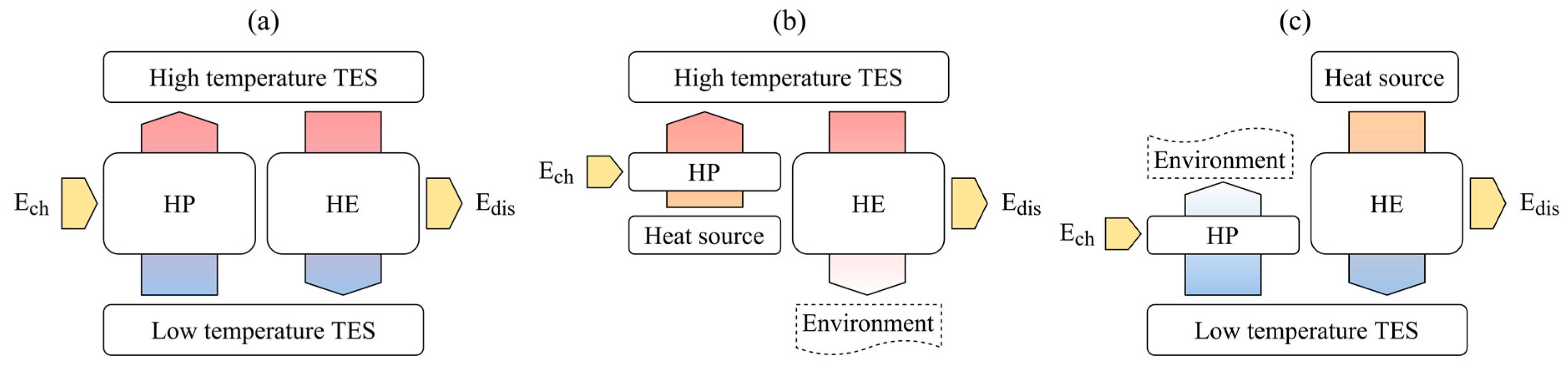
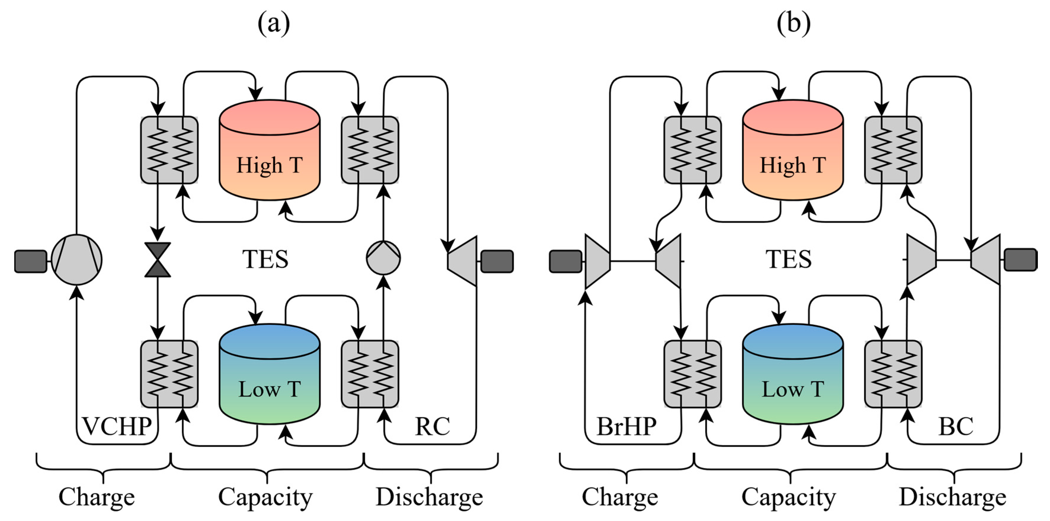
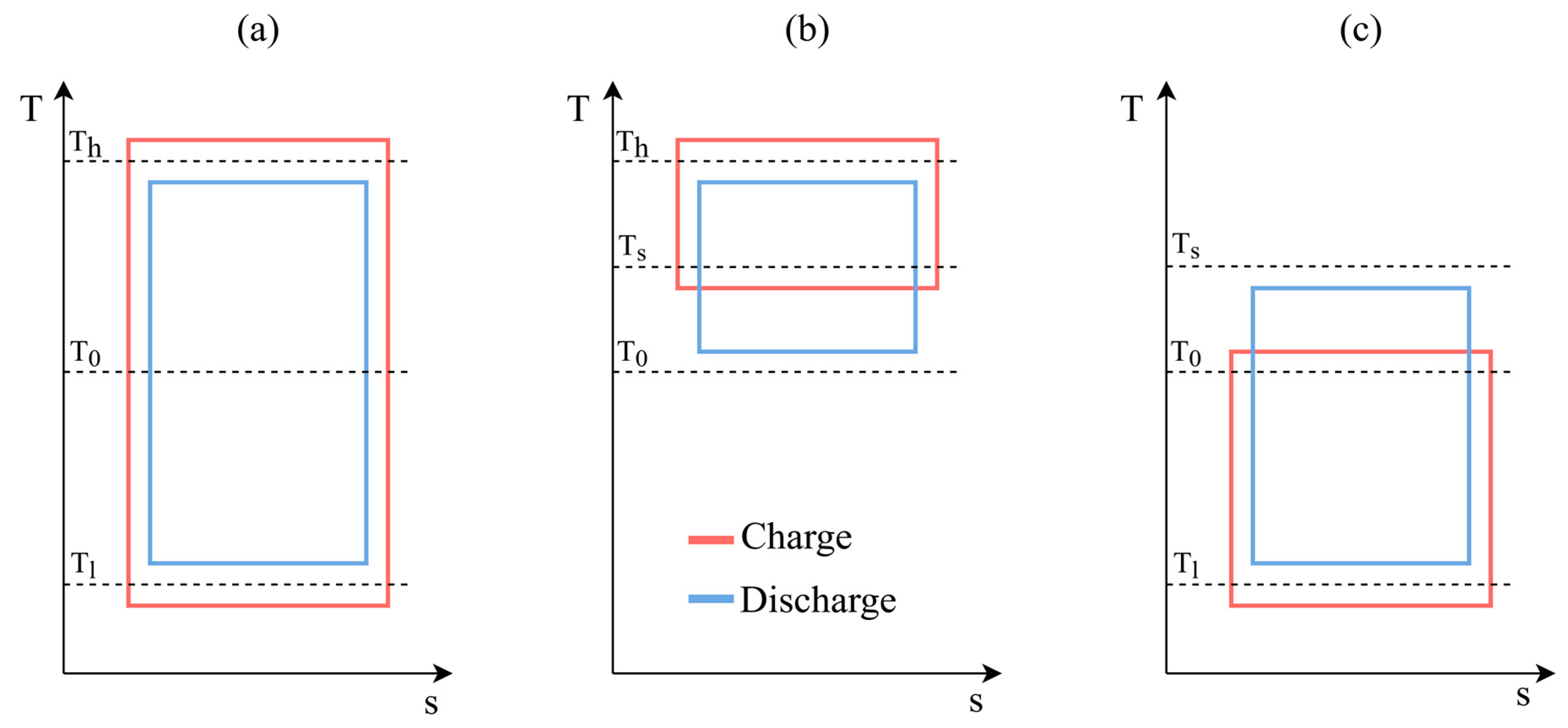
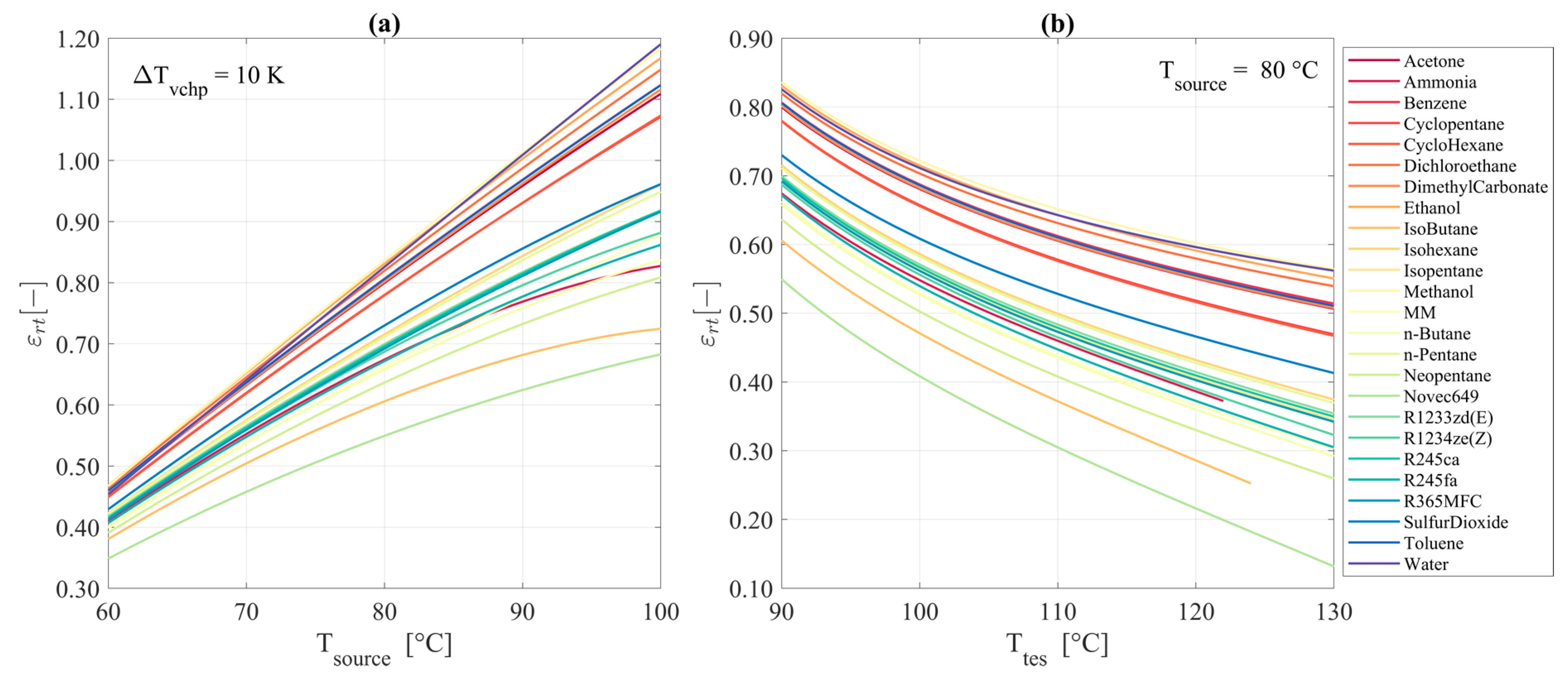
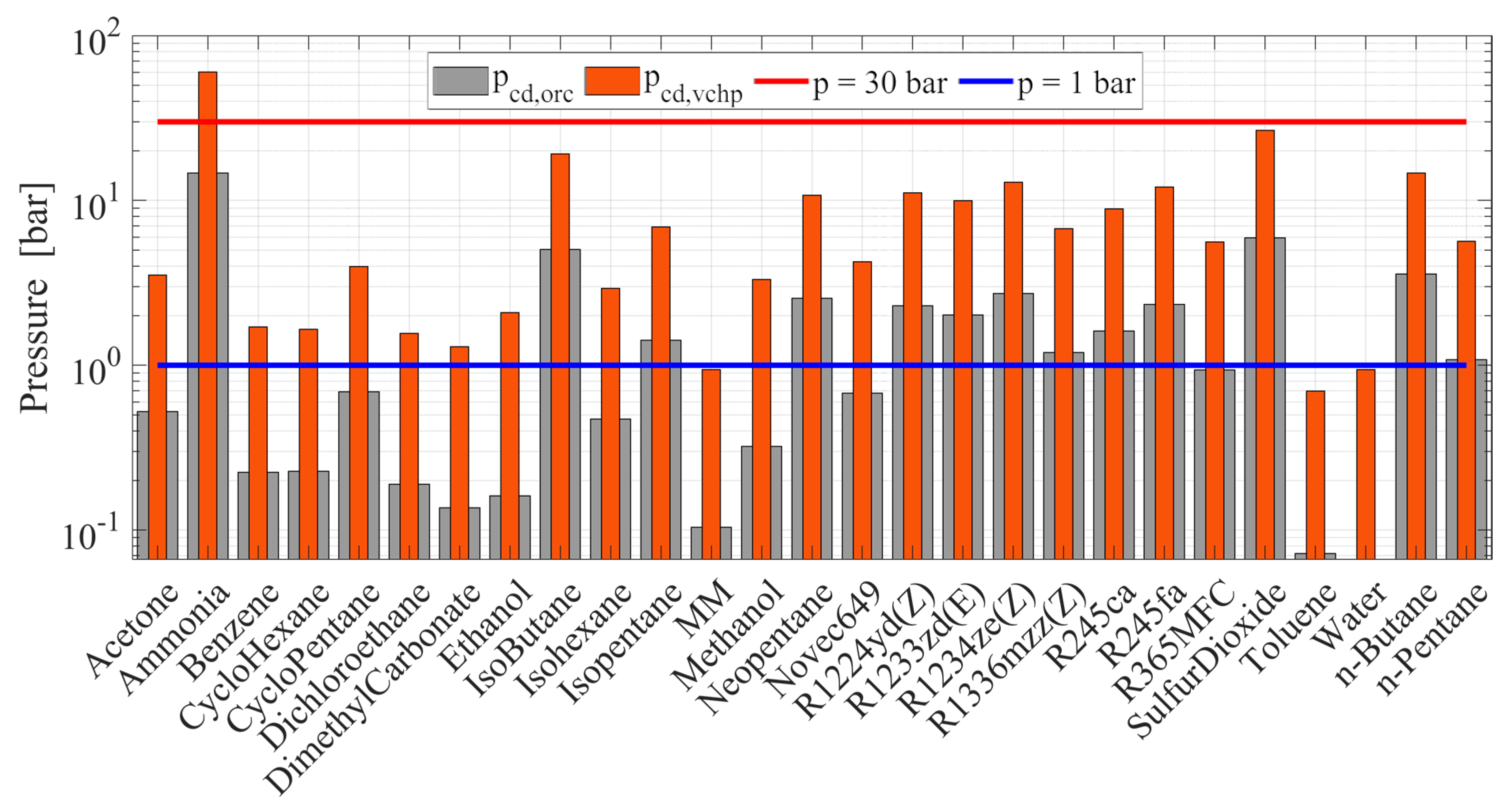
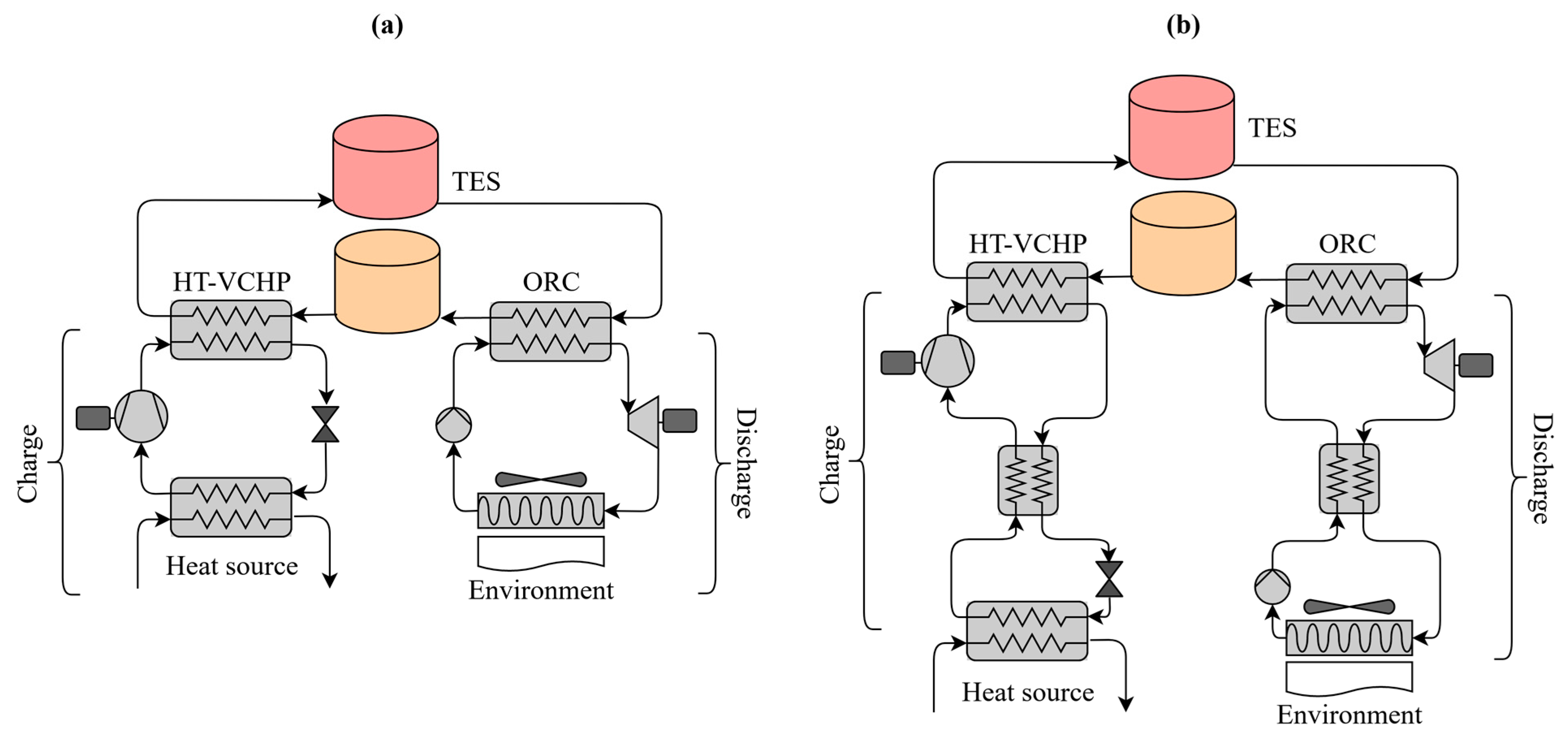
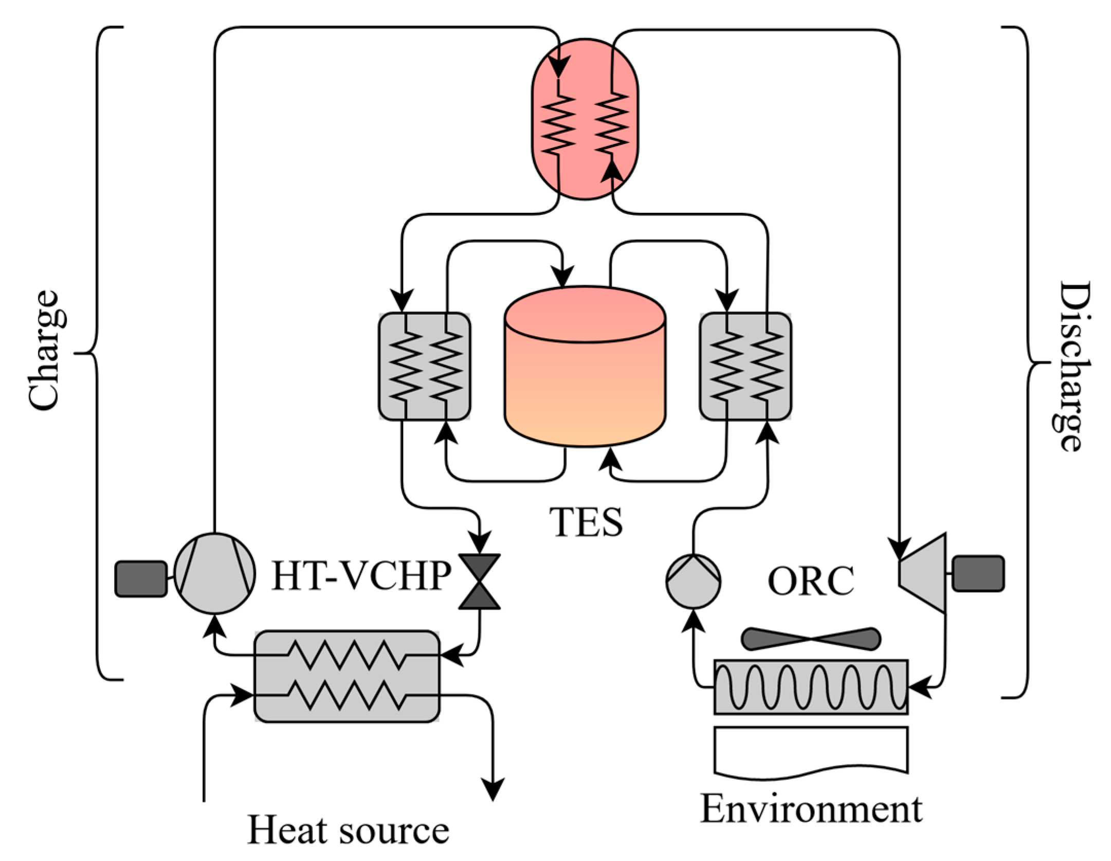
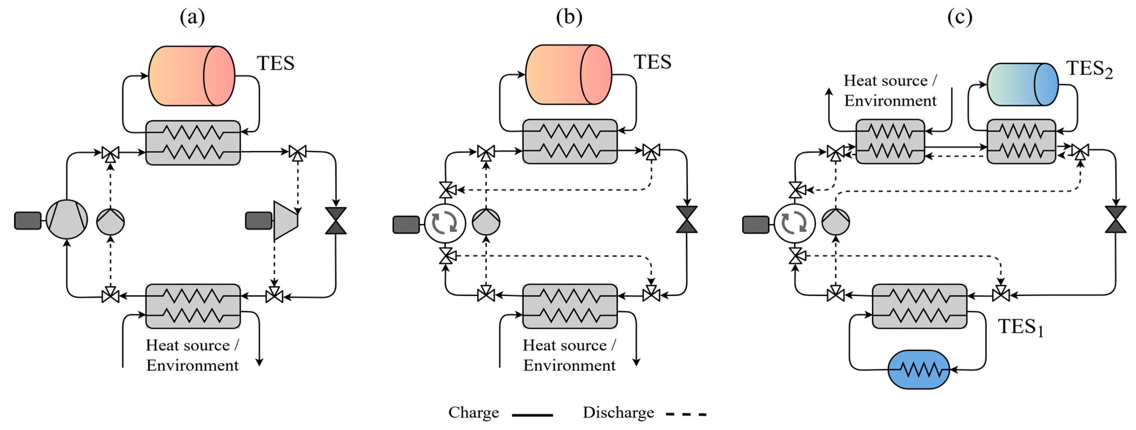
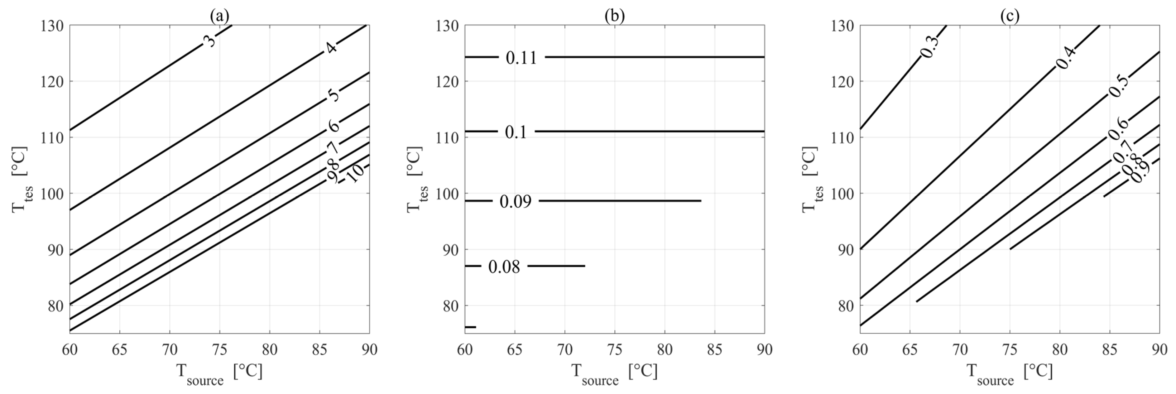
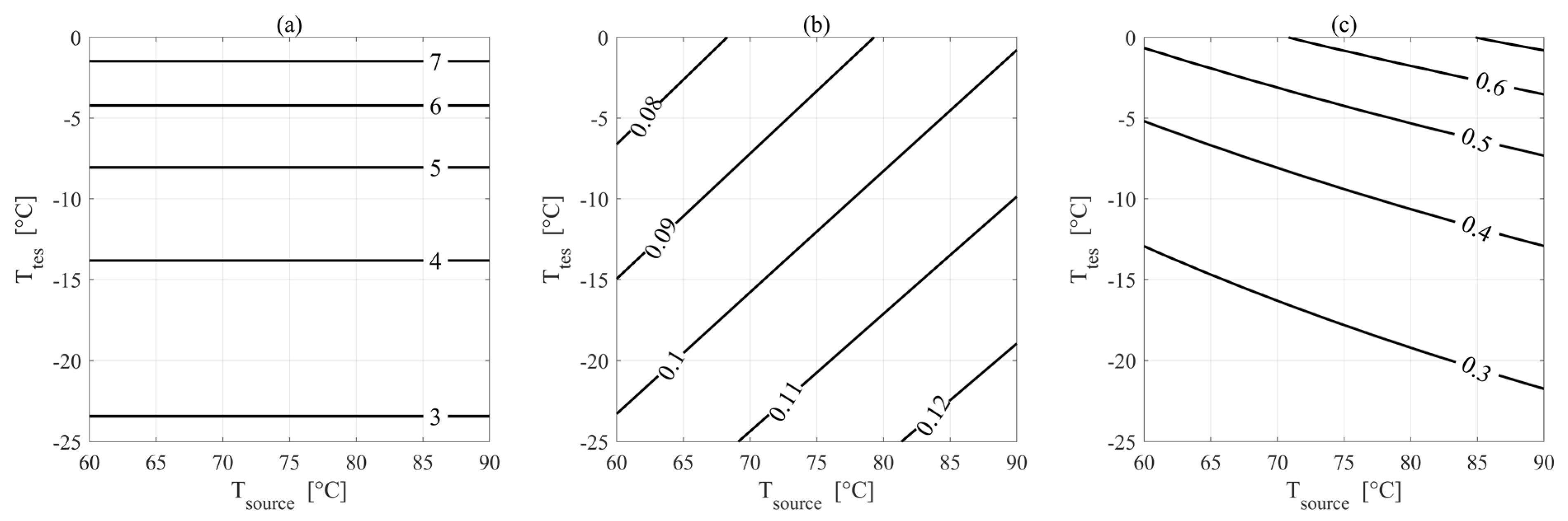
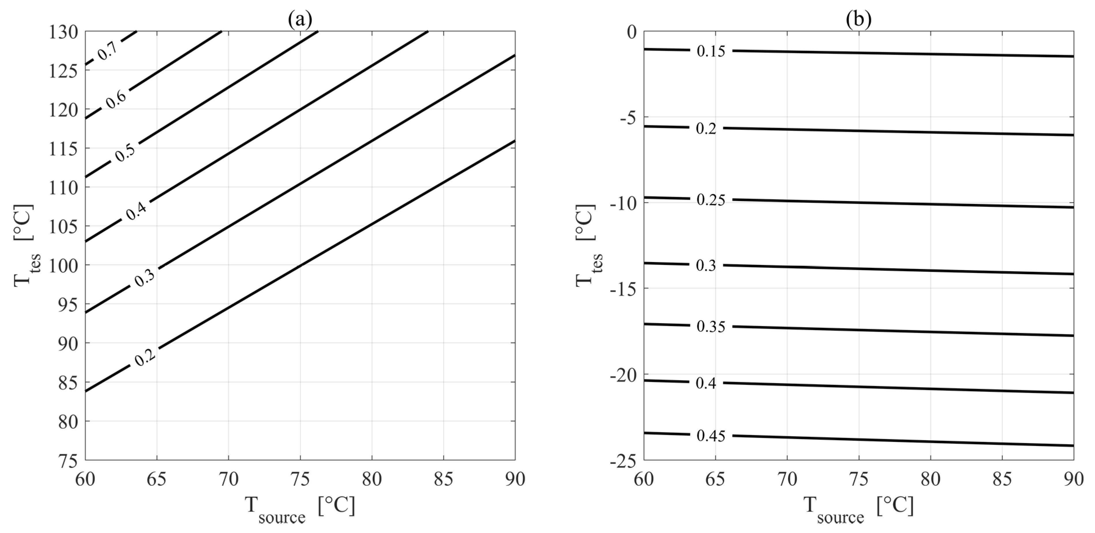
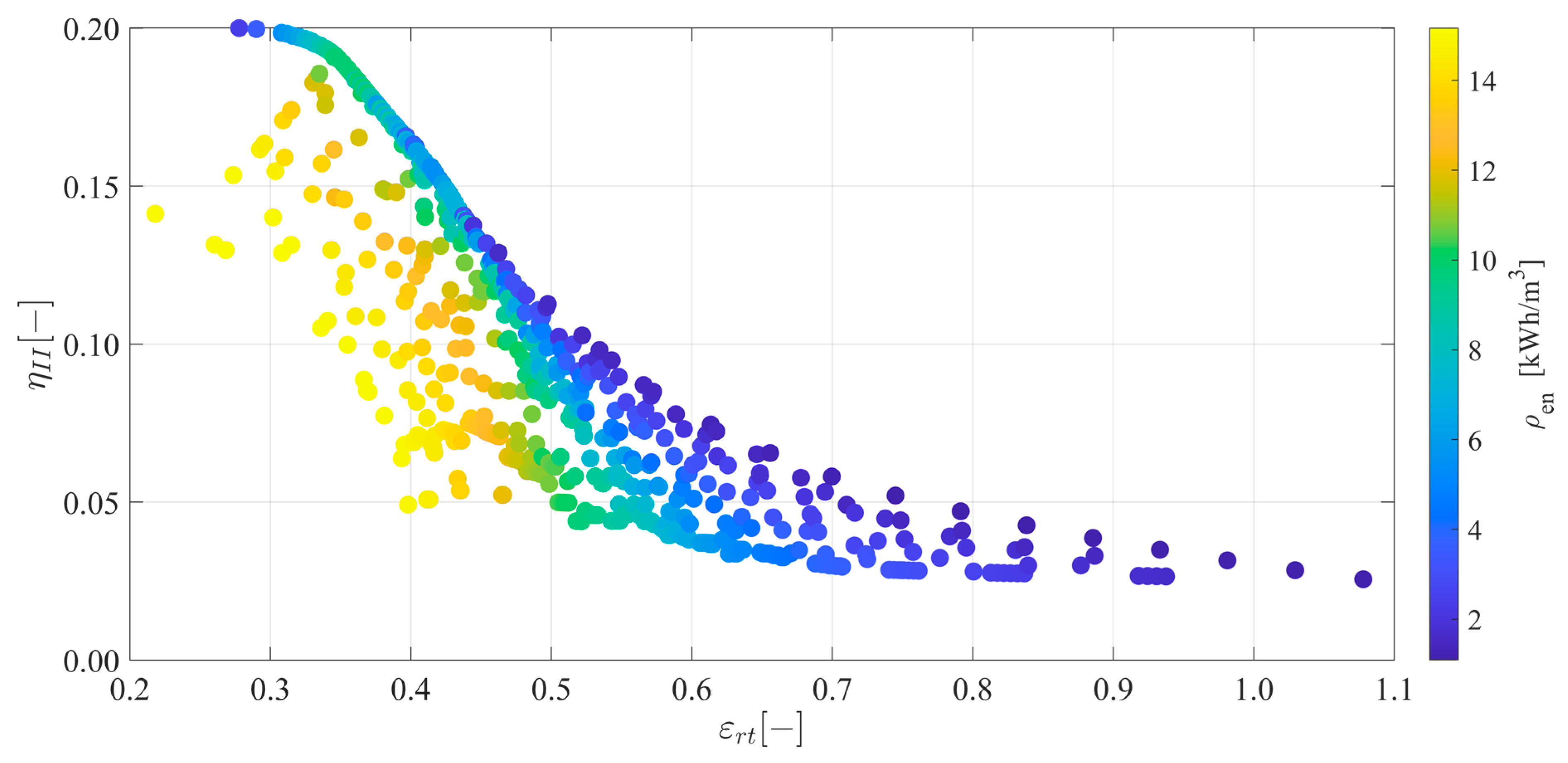
Table 1.
Summary of cited studies according to the listed technical topics.
| Configuration | TES Technology | Reversible | Components | ||||||
|---|---|---|---|---|---|---|---|---|---|
| PCM | Sensible | Hybrid | No | Partly | Fully | Heat Exchangers | Machines | Operating Fluid | |
| Hot TI-PTES | [22] | [25,28,41,42] | [6,51,52,54] | [6,22,66,28,41,43,51,52,53,58,59] | [25] | [23,47,60,61,62,63,64,65] | [41,44,45] | [41,46,47,48,49,50] | [22,28,47,48,51,52,54,59] |
| Cold TI-PTES | [24] | [24] | |||||||
Table 2.
Studies that deal with the listed analysis topics.
| Experimental | Economic | Integration within Energy Networks |
|---|---|---|
| [26,47] | [41] | [6,52,58,66] |
Table 3.
Qualitative comparison between “hot TI-PTES” and “cold TI-PTES”. The tendency of a configuration to deal with the related issue positively is marked with a ✓. Alternatively, an x is used.
Table 3.
Qualitative comparison between “hot TI-PTES” and “cold TI-PTES”. The tendency of a configuration to deal with the related issue positively is marked with a ✓. Alternatively, an x is used.
| Configuration | εrt | Use of PCM | Use of Heat | KPI Trade-Off | |
|---|---|---|---|---|---|
| Hot TI-PTES | ✓ | x | ✓ | x | x |
| Cold TI-PTES | x | ✓ | x | ✓ | x |
© 2020 by the authors. Licensee MDPI, Basel, Switzerland. This article is an open access article distributed under the terms and conditions of the Creative Commons Attribution (CC BY) license (http://creativecommons.org/licenses/by/4.0/).
Share and Cite
MDPI and ACS Style
Frate, G.F.; Ferrari, L.; Desideri, U. Rankine Carnot Batteries with the Integration of Thermal Energy Sources: A Review. Energies 2020, 13, 4766. https://0-doi-org.brum.beds.ac.uk/10.3390/en13184766
AMA Style
Frate GF, Ferrari L, Desideri U. Rankine Carnot Batteries with the Integration of Thermal Energy Sources: A Review. Energies. 2020; 13(18):4766. https://0-doi-org.brum.beds.ac.uk/10.3390/en13184766
Chicago/Turabian StyleFrate, Guido Francesco, Lorenzo Ferrari, and Umberto Desideri. 2020. "Rankine Carnot Batteries with the Integration of Thermal Energy Sources: A Review" Energies 13, no. 18: 4766. https://0-doi-org.brum.beds.ac.uk/10.3390/en13184766
Note that from the first issue of 2016, this journal uses article numbers instead of page numbers. See further details here.