Experimental Study on the Mechanical Properties of Rock Fracture after Grouting Reinforcement

1
State Key Laboratory of Geomechanics and Geotechnical Engineering, Institute of Rock and Soil Mechanics, Chinese Academy of Sciences, Wuhan 430071, Hubei, China
2
University of Chinese Academy of Sciences, Beijing 100049, China
*
Author to whom correspondence should be addressed.
Energies 2020, 13(18), 4814; https://0-doi-org.brum.beds.ac.uk/10.3390/en13184814
Submission received: 20 July 2020
/
Revised: 8 September 2020
/
Accepted: 9 September 2020
/
Published: 15 September 2020
(This article belongs to the Special Issue Coal Mining Sustainable Development)
Abstract
:Grouting reinforcement plays an important role in repairing fractures and improving the strength of the surrounding rock. To address practical engineering challenges such as caving and chip off-falling of surrounding rock in deep roadways, normal splitting was adopted to prefabricate fractures on rock samples gathered from underground coal mines. This was done to better match the rock fracture specimen with actual conditions. Based on the elementary unit of a fracture surface, systematic experiments were conducted on the tensile properties of rock fractures after grouting reinforcement, and the shear properties were studied after considering the presence of gas. As per the results, the tensile strength of rock fractures increased with the increase in viscosity of grout, but the overall tensile strength was relatively low. The overall tensile effect of surrounding rock was improved less by grouting approach. When the presence of fracture gas in grouting was considered, the peak shear strength of fractures after grouting was 8.34–29.9% less than that without considering the fracture gas. The cemented pore surface produced by unsaturated cementation in the grouting reinforcement was the main cause of reduction in cohesion and frictional angle of rock fractures. The conclusions of this study have great significance for guiding engineering grouting and evaluating the grouting effect.
1. Introduction
Coal is one of the most important energy sources in the world. To achieve a sustainable exploitation of coal, mines around the world have entered the stage of deep-buried mining. Compared with shallow-buried roadways, the contrast between the high stress and low strength of deep surrounding rock is extremely prominent. For deep surrounding rock with high stress and fracture development, grouting reinforcement can significantly improve the structure and mechanical properties of fractured rock masses [1,2,3,4]. In grouting fractured rock, the grout diffuses, flows into the fracture, and finally solidifies. This fills the fracture, resulting in the cementation of relatively fractured rock into a relatively intact block, and it enhances the strength and impermeability of the whole rock [5,6,7]. Research on grouting reinforcement mechanisms has mostly focused on changes to the macro-mechanical parameters and physical properties of the rock mass after grouting, and there is a lack of research on the scale of the fracture surface [8,9,10,11,12]. Indeed, the existence of a fracture surface in the rock mass impacts the mechanical properties of the interaction between rocks. The combination of “fracture” and “rock” is equivalent to “rock”, which deviates from the objective nature of the structural characteristics of fractured rock mass. In the actual grouting engineering of fractured rock mass, the grouting reinforcement effect does not act on the rock mass, nor the individual rocks, but acts on the mechanical properties of the fracture between the rocks. Thus, the mechanical properties of the fractured surrounding rock are affected [13,14,15].
When a fractured rock mass is reinforced by grouting, the direct object of the grouting is the fractured surface. The direct effect of grouting reinforcement is to change the mechanical properties of the fractured surface. A fracture is the basic unit of grouting. To study the mechanism of grouting for fractured rock masses, it is necessary to study the influence of grouting on the mechanical properties of fractured surfaces.
The coal mine in the Huainan mining area has weak surface separation at the immediate roof of the working face. During the stopping process, the roof of the working face may be subjected to caving and chip off-falling in the long run, severely threatening the safety of personnel and mining equipment. Grouting is an effective approach to reinforce the surrounding rock. Through field investigation, it is known that rock fractures after grouting reinforcement are subjected to tensile stress and shear stress. It is also known that in the grouting process, gas presence (mash gas and air) in fractured rock affects the grouting diffusion and, consequently, impacts the reinforcement effect [16,17].
Herein, based on scientific problems faced in the engineering field and the elementary unit of rock fracture, the tensile properties of rock fractures after grouting and the shear properties of rock fractures, considering the presence of gas, were systematically studied using coal mine rock samples after processing. The corresponding mechanical properties and rules were obtained, providing guidance for relevant issues in engineering.
2. Materials and Methods of Tensile and Shear Tests
2.1. Theory of Unsaturated Cementation of Grouting Fractures
Several engineering studies have characterized the occurrence of gas (mash gas, air, etc.) in rock fractures, and it is a non-negligible factor affecting the grouting effect. Owing to the presence of fracture gas, a grout–gas displacement phenomenon occurs in the grouting process. When the fracture is blocked by grout, the gas stays in the fracture, forming immiscible grout bubbles on the phase surface. When induration occurs through grout cementation, a cemented pore surface is formed in the grout bubble area due to the presence of gas. The effect of this factor has not been considered in the existing theoretical and experimental studies on grouting cementation reinforcement; i.e., rock fractures after grouting have been assumed to be in a state of saturated cementation. Analysis of the mechanical properties and study of the reinforcement mechanism of fractured rock based on a saturated cementation assumption would inevitably lead to certain deviations.
Based on actual situations in the engineering field, the present tests considered gas presence in a rock fracture. Shear property tests were performed on the unsaturated cemented body formed in the rock fracture after grouting. The obtained results are closer to the engineering field.
2.2. Preparation of Grouted Rock Fracture Specimen
2.2.1. Rock Fracture Specimens for Tensile Test
After grouting reinforcement of surrounding rock, its tensile properties significantly affect the integrity of surrounding rock and the stability of the roadway. Therefore, tensile mechanical property tests were conducted on a standard cylinder rock fracture with 50 mm diameter and 100 mm height. The key for an experimental study on the tensile properties of grouting rock fractures is the preparation of the rock fracture. The complex geological conditions of rock in field engineering pose challenges to the selection of virgin rock fractures in surrounding rock. The literature shows that researchers have more often used artificially prefabricated fractures instead. However, there is a considerable difference in roughness, aperture, etc. between artificially prefabricated and naturally occurring fractures. For the present tests, sampling was conducted in the surrounding rock of a deep-buried coal mine in the Huainan mining area, and the samples have been fabricated as standard cylinder rock samples. It was known through preliminary tests that the chosen rock samples were of sandstone, with a mean density of 2.9 × 10³ kg/m3, elastic modulus of 34.34 GPa, compressive strength of 105.46 MPa, and tensile strength of 10.54 MPa. Theorem-type environments (including propositions, lemmas, corollaries, etc.) can be formatted as follows.
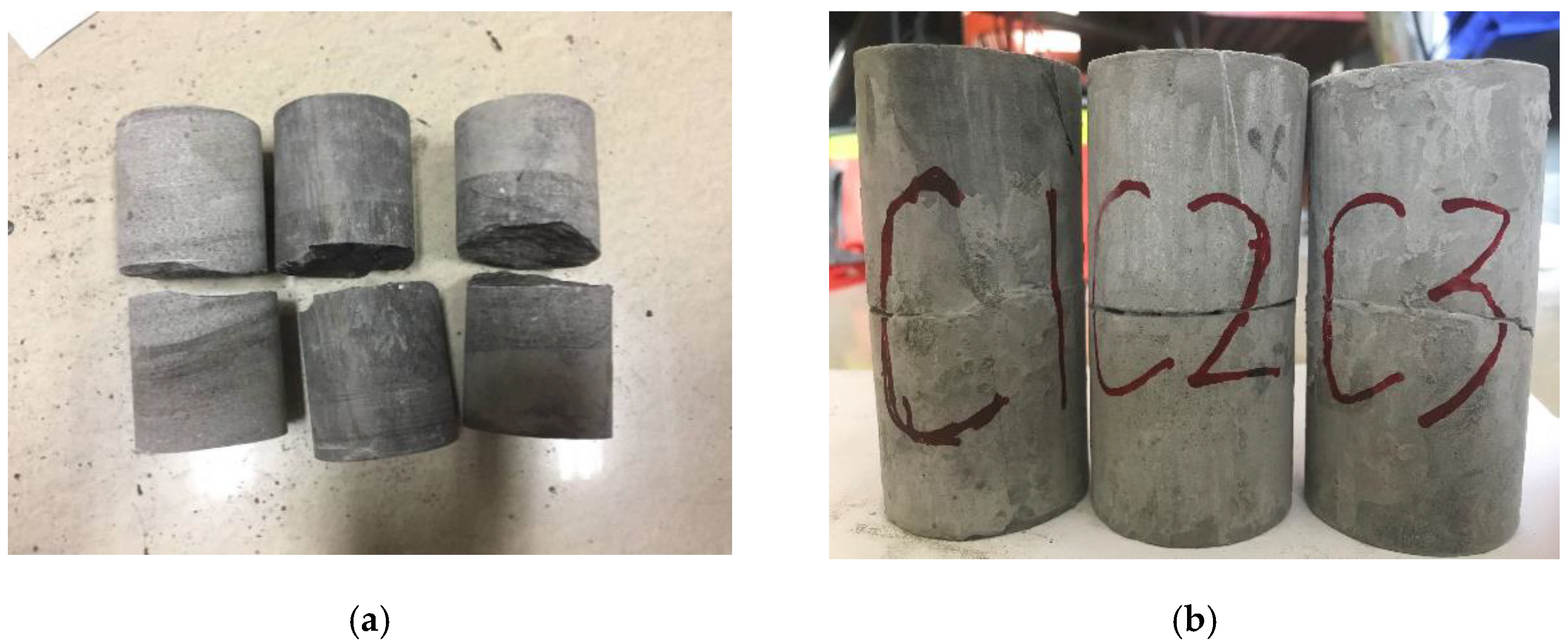
To prepare the fracture, a normal splitting test was conducted at the center of the cylinder specimen, so that the sample was split into upper and lower sections. As shown in Figure 1a, to control a single variable, the rock samples with greater inclination on the split surface were discarded, and the qualified rock samples were selected. After splitting, a total of nine specimens were qualified, and they were clustered into three groups, namely A, B, and C, with three specimens in each to investigate the effect of cement grout viscosity (i.e., water–cement ratio) on the tensile properties of the rock fracture. Ordinary Portland cement with a compressive strength of 42.5 MPa was used. The grout was prepared according to predefined water–cement ratios, and then grouting reinforcement was performed on each group. Lastly, as shown in Figure 1b, the specimens were conserved for 28 d at room temperature (20°).
Three water–cement ratios were designed for the present tests, and the tensile tests were performed on the three groups (A, B, and C) of fracture specimens separately. The peak tensile strength was obtained by averaging the three specimens in each group, and these values are listed in Table 1.
2.2.2. Rock Fracture Specimens for Shear Test
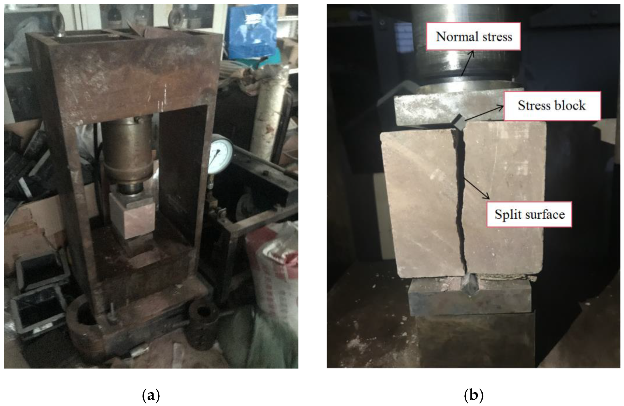
The samples were fabricated from an intact rock block that was collected underground. The block was split into cube blocks via fabrication, the dimensions of which were 150 × 150 × 150 mm. Normal splitting was adopted to split the cube blocks formed by fabrication. As shown in Figure 2, rocks with greater fracture surface inclination were discarded; thus, a total of eight qualified blocks of rock after splitting were selected, which were further divided into two groups: Group A and Group B.
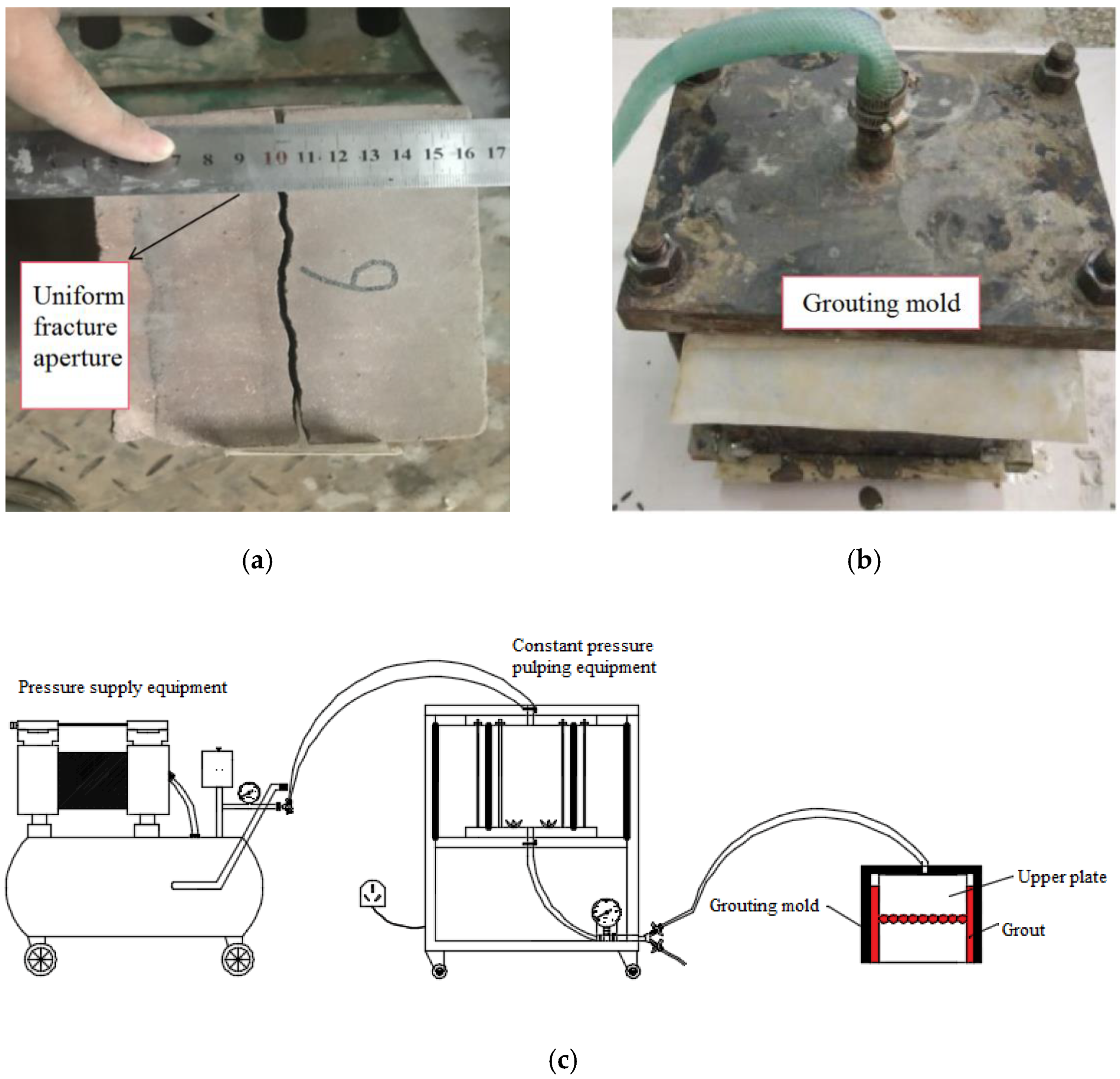
The size of the rock fracture in the shear tests was large (150 × 150 mm). To study the influence of gas on grouting reinforcement, the viscosity of the grout should be kept the same, along with the aperture of the fracture. Therefore, self-developed fracture grouting equipment was used, and the grouting procedure was as follows [17,18]:
- (1)
- The upper and lower plates of fractured rock were placed in the grouting mold, and the distance between the plates was maintained as constant (i.e., consistent aperture of fracture). The grouting mold was sealed by bolts, as shown in Figure 3a,b.
- (2)
- Ordinary Portland cement with a compressive strength of 42.5 MPa was prepared into a grout. The cement grout with a water–cement ratio of 1:1 was introduced into the grout reservoir pipe in the grouting equipment, and a turbine propeller was turned on to stir the grout constantly.
- (3)
- The exit of the grout reservoir pipe was connected to the grouting mold. The air compressor was opened, and the pressure was adjusted to a constant value of 0.5 MPa. The grouting was performed and the system was maintained for 30 min, as shown in Figure 3b,c.
- (4)
- After 1 d, form stripping was conducted, and then conservation was performed for 28 d.
These tests primarily studied the change in shear mechanical properties of an unsaturated cemented body formed in a rock fracture in the presence of gas. Hence, after grouting was completed, when the grout was initially solidified, the same amount of air was injected into four fractures in Group B, while Group A was taken as the control group. During the injection process, the four sides of the fracture were sealed to prevent gas from escaping. The gas was then compressed into bubbles within the consolidated body formed by the grout so that several cavities formed within the consolidated body, namely unsaturated cementation.
2.3. Test Methods
2.3.1. Method of Tensile Test
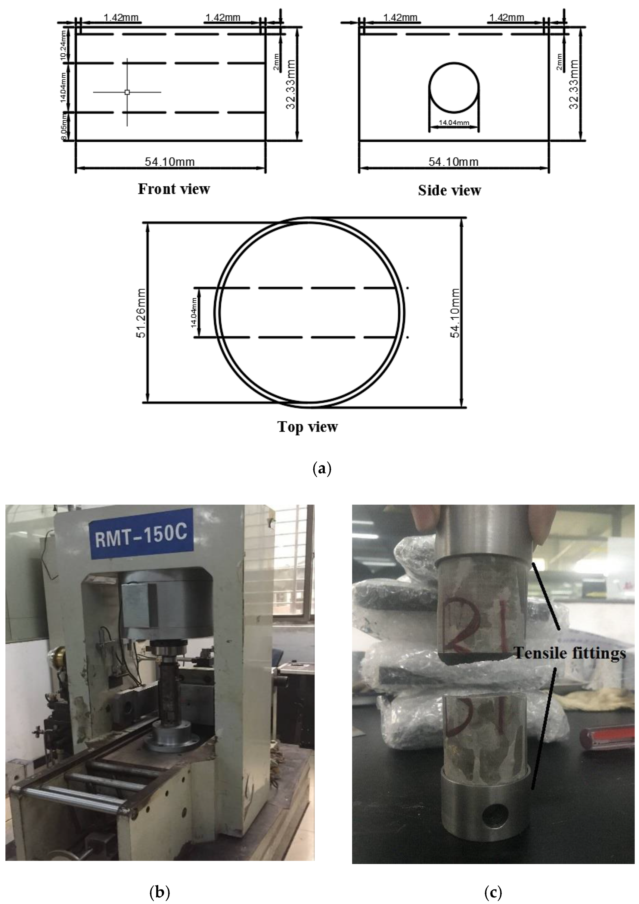
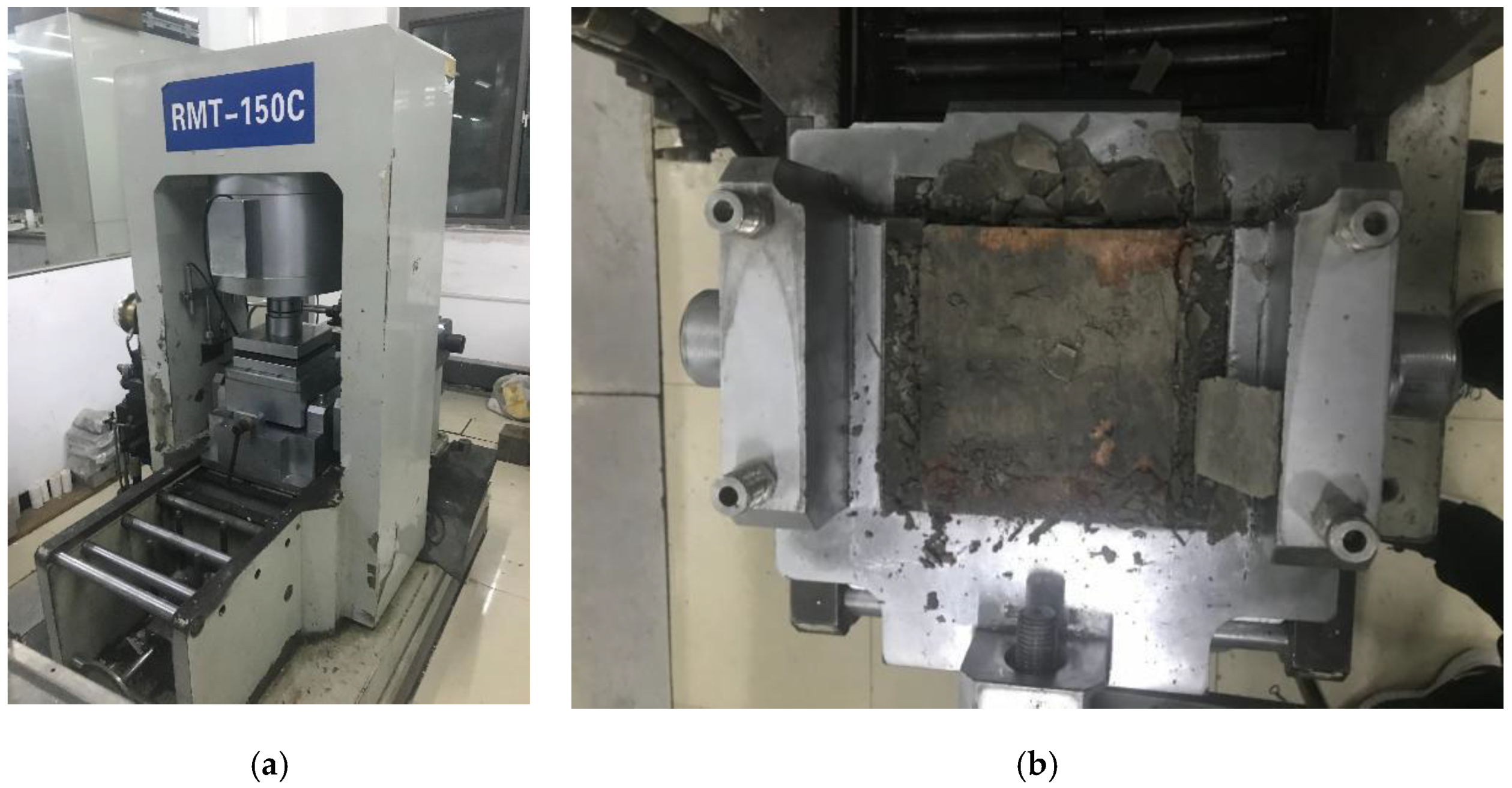
Tests were conducted on the rock mechanics loading system, RMT-150C, at the State Key Laboratory of Geomechanics and Geotechnical Engineering. The tensile fittings were tailored into the required dimensions and fixed at both ends of specimens. The dimensions of the tensile fittings are shown in Figure 4a, and the tensile fittings are shown in Figure 4c. A low loading rate of 0.0020 mm/s was adopted for loading. The process of the tensile tests is shown in Figure 4b.
2.3.2. Method of Shear Test
Shear tests were conducted on the loading test system of rock mechanics, RMT-150C. Group A consisted of four rock fractures with no gas filled, while Group B consisted of four rock fractures with gas filled. The grouted fractured rock was placed in a shear cell, and vertical loads corresponding to preset normal stress were loaded to 2, 4, 6, and 8 MPa, respectively. After successful loading and 5 min of stabilized pressure, horizontal shear displacement was performed at a loading rate of 0.02 mm/s until shear failure. The process of the shear test is shown in Figure 5.
3. Tensile and Shear Properties of Grouted Rock Fracture
As per Table 1, the overall tensile strength of the grouted rock fracture was relatively low, always less than 1 MPa. At different viscosities of cement grout, i.e., at different water–cement ratios, the tensile strength of the fracture increased as the water–cement ratio increased. Nevertheless, the number of test parameters set for water–cement ratios was low (three parameters). Hence, the conclusion is suitable only for grout in a water–cement range of 0.5:1–1.5:1. In general, the effect of cement grout on the tensile properties of fractured rock was limited. If the surrounding rock of the roadway is further subjected to tensile failure, approaches other than grouting or the development of new grout would be needed.
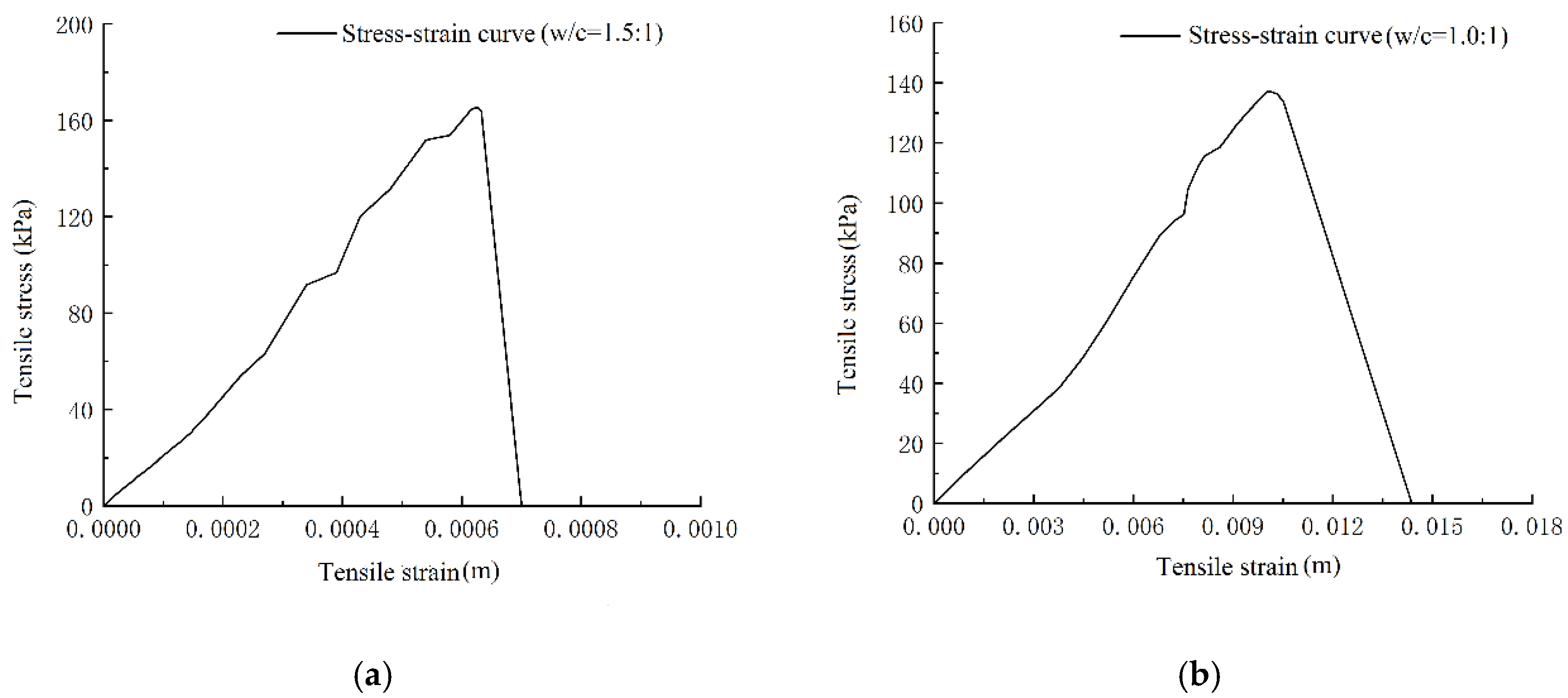
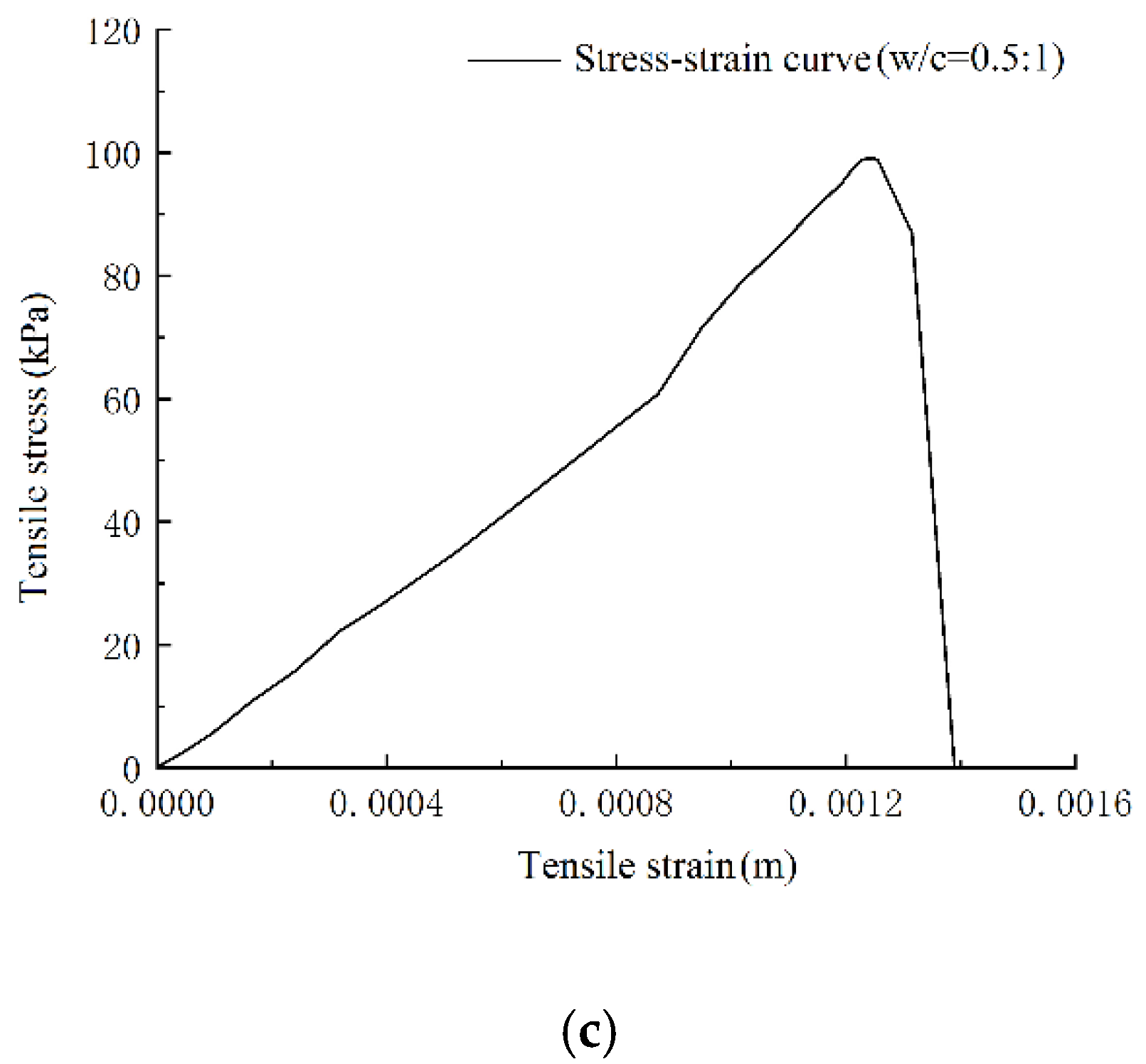
As shown in Figure 6, one stress–strain curve was selected from each group for analysis. The tensile stress of the grouted rock fracture increased with the increase in strain, approximately showing a positive correlation. After reaching peak tensile strength, brittle failure occurred at the fracture of the rock, and the tensile stress rapidly declined to zero. By comparing the three curves in Figure 6a–c, it can be seen that a lower water–cement ratio of grout yielded a lower peak stress, a smaller gradient of stress–strain, and a greater strain corresponding to peak stress. Compared with the tensile and shear strengths of rock fractures in the literature, the tensile strength and corresponding strain were extremely low. Hence, the grouting measure or grouting with cement grout was not capable of significantly improving the tensile performance of fractured rock.
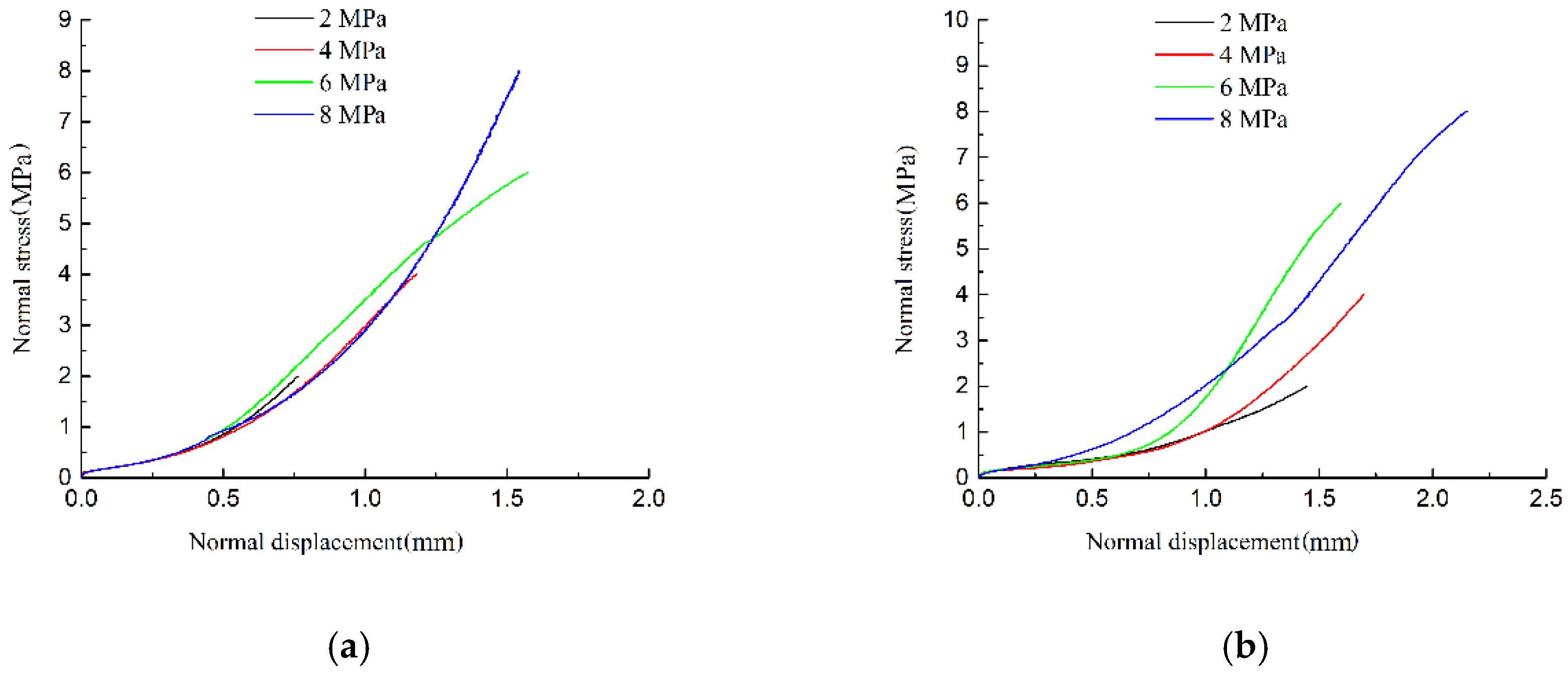
The normally loaded stress–displacement curve of the grouted rock fracture is presented in Figure 7. The normal stress of the grouted rock fracture increased with the increase in normal displacement, and the trends of the stress–displacement curves were consistent between the conditions with and without gas, i.e., the elastic modulus (variation of slope gradient) demonstrated an increasing trend. The reason for this phenomenon is that, at the early phase of normal loading, small pores with a relatively large size existed inside the grout induration and between the grout and fracture surfaces, and relatively large normal displacement was needed to produce relatively small stress. As the small pores were compacted, relatively smaller normal displacement was needed to produce the same stress. The elastic modulus of the stress–displacement curve was almost the same under the same conditions, irrespective of gas occurrence. By the comparison of Figure 7a,b, with the same requirement for normal stress, the elastic modulus for the stress–displacement curve with gas occurrence was slightly lower than that without gas. The reason may be that unsaturated cementation occurred during grouting in the presence of gas; that is, the formed consolidation contained some cavities. Thus, the required normal displacement was large when the same normal pressure was forced, and the elastic modulus was smaller than the elastic modulus without gas. These results demonstrate that when the presence of gas is considered, the unsaturated cemented body formed by grout induration affects the relationship between normal stress and the displacement of induration.
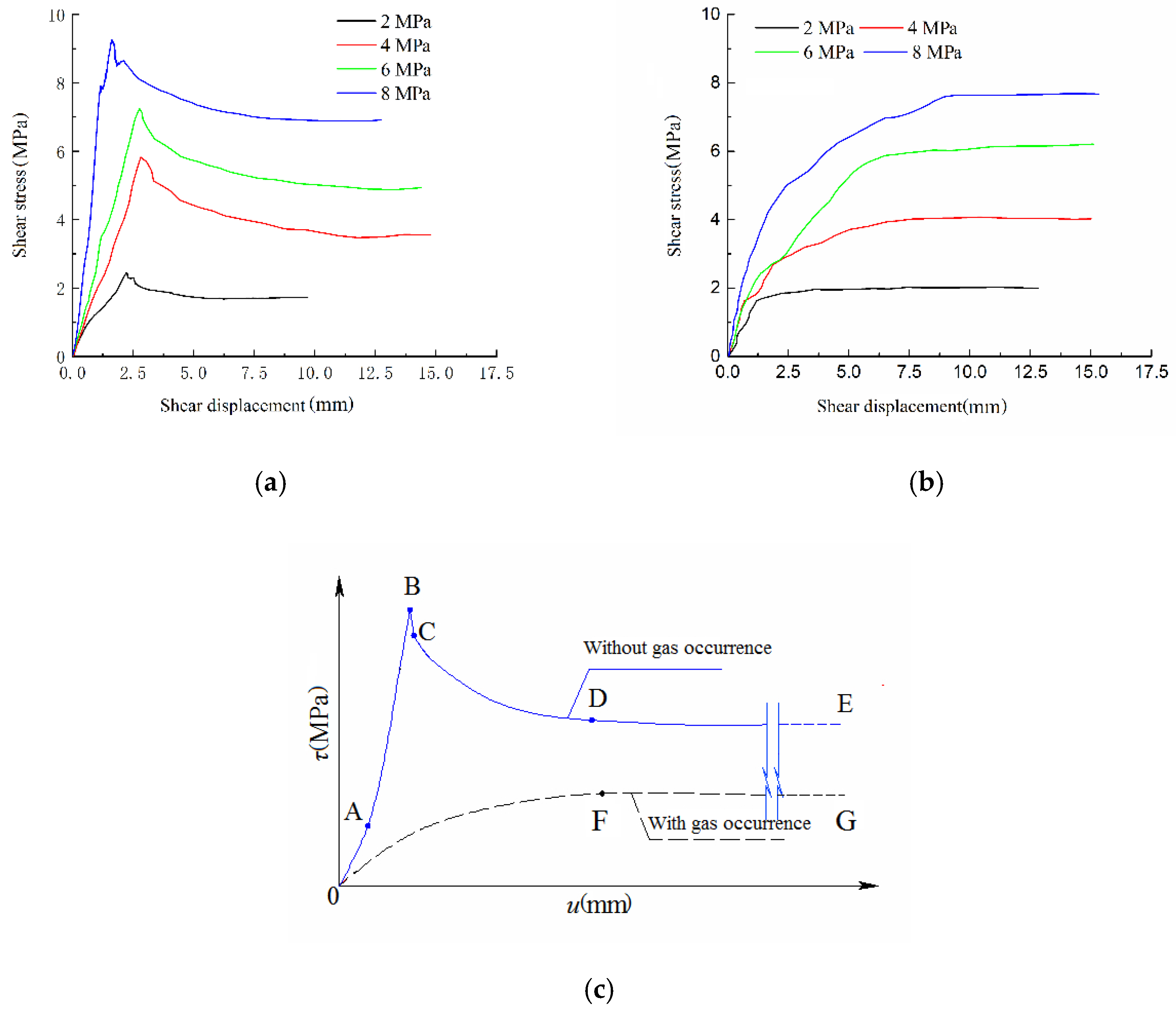
The shear stress–displacement curves of the grouted rock fracture are presented in Figure 8. Without gas occurrence, in the early phase, the shear strength curve of the grouted rock fracture displayed elastic variation, and stress declined as displacement increased after reaching peak shear strength. Subsequently, the stress stabilized around residual shear strength. With gas occurrence, the shear strength curve of the grouted rock fracture rose constantly as shear displacement increased while the rate gradually became lower. The curve finally stabilized around the peak shear strength without evident residual shear strength.
The shear stress–displacement characteristic curves of the rock fracture under these two conditions are shown in Figure 8c. When gas occurrence was not considered, the shear stress–displacement curve was divided into five sections: Section OA denotes the initial rise, when stress slowly increased with the increment of displacement; Section AB denotes a linear rise, when stress was directly proportional to displacement, reaching peak stress; Section BC denotes a rapid decline, when stress rapidly reduced in small intervals of displacement after peak stress was reached; Section CD denotes a slow decline, when stress gradually reduced with a continuous increase in displacement, and the reduction rate slowed down until it essentially remained unchanged; Section DE denotes the stable stage, when the residual strength of stress remained almost the same. When gas occurrence was considered, the shear stress–displacement curve was divided into two sections: Section OF denotes the rising stage, when stress increased with the increase in displacement (with a decrease in the rate, stress reached a peak value); Section FG denotes the stable stage, when stress remained almost constant with an increase in displacement.
Under the same conditions (with or without gas occurrence), with the increase in normal stress, both the elastic modulus of the shear stress–displacement curve and the peak shear strength increased. Table 2 lists the peak shear strength values under the two conditions. For the same normal stress, the peak shear strength with gas occurrence was 8.34%~29.9% lower than that without gas occurrence.
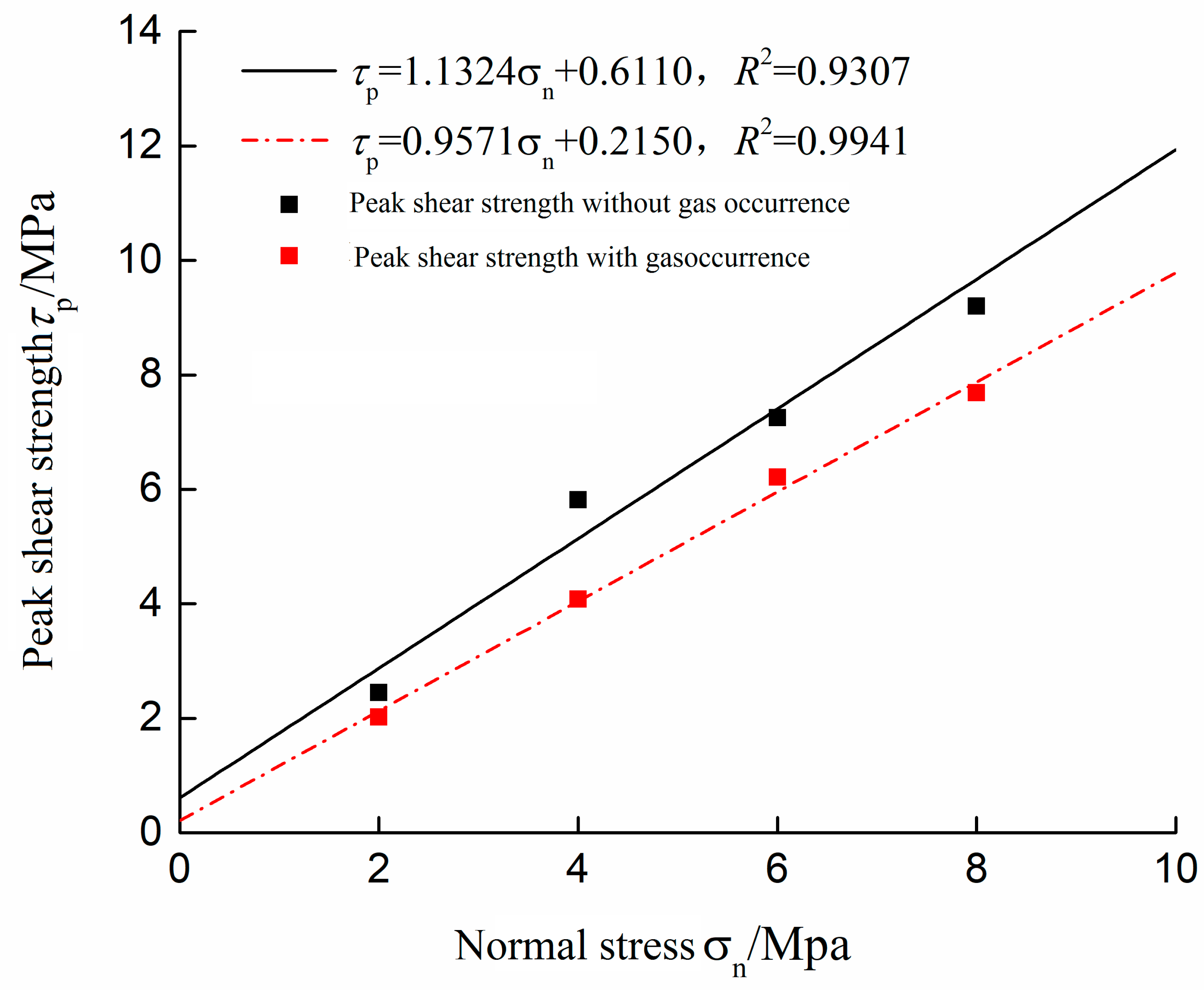
By fitting the data in Table 2, the peak strength curves of the grouted rock fracture with and without gas occurrence were obtained, as shown in Figure 9.
It can be seen by analyzing the fitting curves in Figure 9 that the cohesion was 0.611 MPa and the frictional angle was 64.9° for grouted rock fractures without considering the presence of gas, while the same were 0.215 MPa and 54.9°, respectively, when gas was considered. Owing to gas present in the fracture, the fracture was characterized with a cemented pore surface formed through grouting cementation reinforcement. As a result, after grouting, both cohesion and frictional angle of the fracture reduced, with the former reducing by 64.8% and the latter by 15.4%.
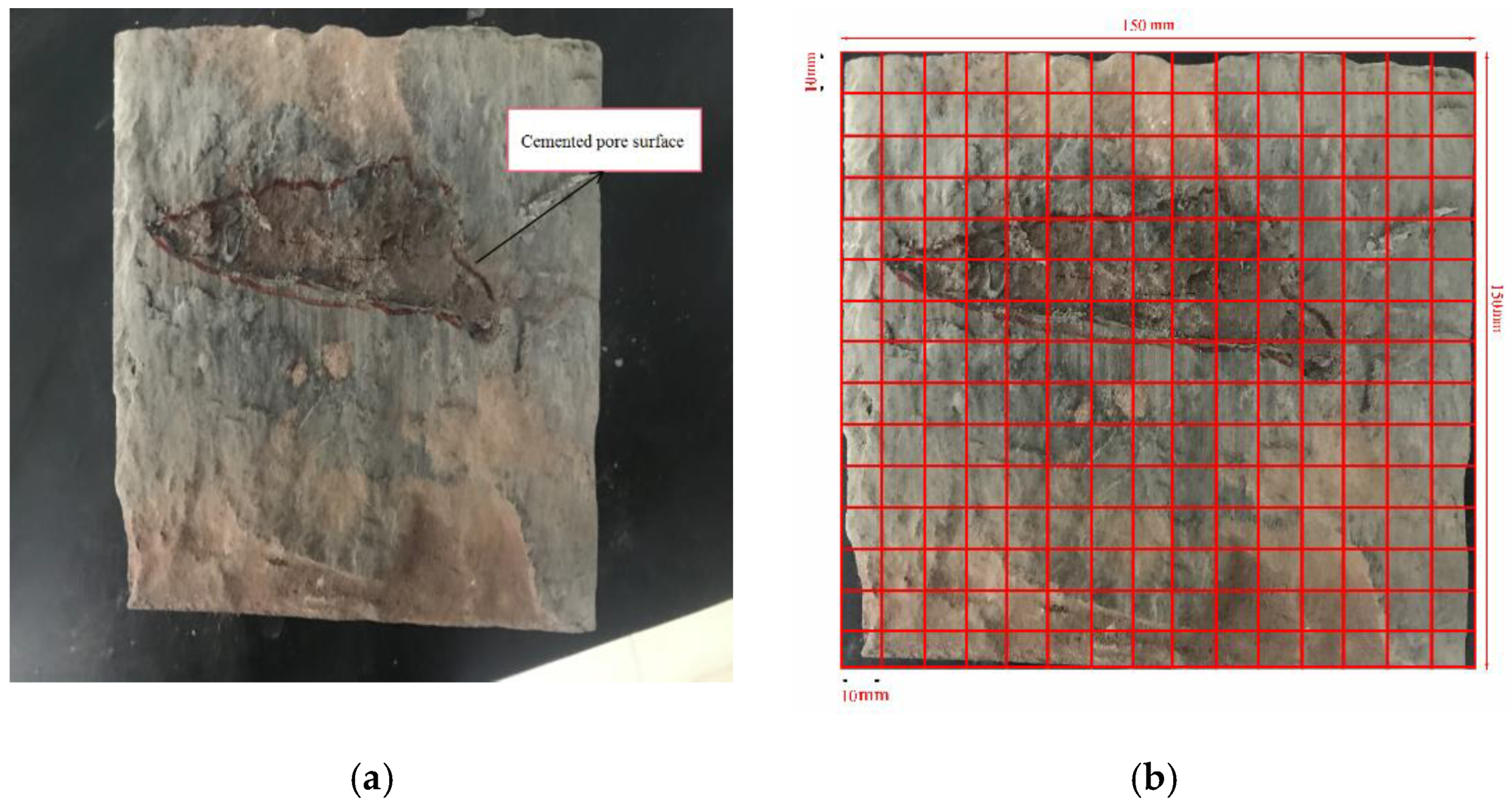
To quantitatively study the effect of gas on grouting, the fracture surface after shear tests was processed. Figure 10a shows the fracture surface after the cleaning process, where the red coil tracing area is the cemented pore surface resulting from gas present in the grout. This figure also shows that when gas was considered, unsaturated cementation occurred in grouting reinforcement. The meshing process was performed on the fracture surface as shown in Figure 10b. Through processing, the cemented pore surface approximately accounted for 12.5% of the fracture surface; i.e., the proportion of unsaturation was 12.5%. Through analysis, the quantitative effect of gas on the grouting of rock fractures was obtained. Primarily, the effect of unsaturated cementation was about one-fifth that of the decline rate of cohesion and 1 time that of the decline rate of frictional angle. This is the preliminary conclusion drawn in the present tests, and systematic tests with control variables should be conducted in follow-up research to conduct an in-depth quantitative study.
4. Conclusions
Herein, grouting reinforcement cementation for deep underground engineering was explored. Tensile and shear tests were conducted on rock fractures after grouting, and several conclusions can be obtained.
- (1)
- The normal splitting approach was applied on standard rock samples and cube rock to prepare fractures, which is close to virgin fractures in rock surrounding a roadway, reflecting relatively close-to-real situations.
- (2)
- According to tensile tests on grouted rock fractures, the tensile strength increased with the increase in viscosity of cement grout, but the overall tensile strength was relatively low. Cement grouting did not effectively improve the overall tensile performance of surrounding rock. Hence, a further area to research is developing grout with strong adhesion stress that can enhance the tensile properties. The development of grouting materials is one of the most important directions.
- (3)
- Unsaturated cementation caused by the presence of fracture gas had a considerable influence on grouting effect. Under the same normal stress, the peak shear stress of rock fracture with gas occurrence was 8.34–29.9% lower than that without gas occurrence.
- (4)
- The cemented pore surface produced during unsaturated cementation in grouting cementation was the main cause of the decline of cohesion and frictional angle. The preliminary analysis demonstrated that the impact of the cemented pore surface was about one-fifth that of the decline rate of cohesion and 1 time that of the decline rate of frictional angle. Further work should focus on quantitatively studying the effect of gas occurrence on grouting. Specifically, by changing the generated gas amount and describing the area of cemented pores, the general rules of impact on the shear strength of the fracture can be obtained.
Author Contributions
Conceptualization, H.S. and Y.K.; Data curation, Z.W.; Formal analysis, H.S.; Funding acquisition, B.L. and Y.K.; Investigation, Z.W.; Methodology, B.L.; Project administration, B.L. and H.S.; Resources, B.L. and H.S.; Supervision, B.L. and Y.K.; Validation, B.L. and H.S.; Visualization, H.S.; Writing—original draft, H.S.; Writing—review & editing, H.S. and Y.S. All authors have read and agreed to the published version of the manuscript.
Funding
This work was financially supported by the National Natural Science Foundation of China under Grant Nos. 51974289, 51774267, and 41807250.
Acknowledgments
The anonymous reviewers are greatly acknowledged for reviewing this article and giving their valuable comments.
Conflicts of Interest
The authors declare that they have no conflicts of interest.
References
- Kang, Y.S.; Liu, Q.S.; Xi, H.L.; Gong, G.Q. Improved compound support system for coal mine tunnels in densely faulted zones: A case study of China’s Huainan coal field. Eng. Geol. 2018, 240, 10–20. [Google Scholar] [CrossRef]
- Liu, B.; Sang, H.M.; Liu, Q.S.; Kang, Y.S.; Pan, Y.C.; Lu, C.B.; Zhang, C.Q. New Algorithm for Simulating Grout Diffusion and Migration in Fractured Rock Masses. Int. J. Geomech. 2020, 20. [Google Scholar] [CrossRef]
- Gothall, R.; Stille, H. Fracture dilation during grouting. Tunn. Undergr. Space Techol. 2009, 24, 126–135. [Google Scholar] [CrossRef]
- Kim, H.M.; Lee, J.-W.; Yazdani, M.; Tohidi, E.; Nejati, H.R.; Park, E.S. Coupled Viscous Fluid Flow and Joint Deformation Analysis for Grout Injection in a Rock Joint. Rock Mech. Rock Eng. 2018, 51, 627–638. [Google Scholar] [CrossRef]
- Tani, M.E. Grouting rock fractures with cement grout. Rock Mech. Rock Eng. 2012, 45, 547–561. [Google Scholar] [CrossRef]
- Moon, H.; Song, M. Numerical studies of groundwater flow grouting and solute transport in jointed rock mass. Int. J. Rock Mech. Min. 1997, 34, 206–219. [Google Scholar] [CrossRef]
- Xiao, F.; Zhao, Z.Y.; Chen, H.M. A simplified model for predicting grout flow in fracture channels. Tunn. Undergr. Space Techol. 2017, 70, 11–18. [Google Scholar] [CrossRef]
- Kulhawy, F.H. Stress deformation properties of rock and rock discontinuities. Eng. Geol. 1975, 9, 327–350. [Google Scholar] [CrossRef]
- Barton, N.R. Shear Strength Criteria for Rock, Rock Joints, Rockfill, Interfaces and Rock Masses. J. Rock Mech. Geol. Eng. 2013, 5, 249–261. [Google Scholar] [CrossRef] [Green Version]
- Barton, N.R. Characterization of Fracture Shearing for 4D Interpretation of Fractured Reservoirs. In Proceedings of the 2nd EAGE Workshop on Naturally Fractured Reservoirs, Muscat, Oman, 8–11 December 2013. [Google Scholar]
- Park, J.W.; Lee, Y.K.; Song, J.J.; Choi, B.H. A Constitutive Model for Shear Behavior of Rock Joints Based on Three-Dimensional Quantification of Joint Roughness. Rock Mech. Rock Eng. 2013, 46, 1513–1537. [Google Scholar] [CrossRef]
- Grasselli, G. 3D Behaviour of bolted rock joints: Experimental and numerical study. Int. J. Rock Mech. Min. Sci. 2005, 1, 13–24. [Google Scholar] [CrossRef]
- Lu, C.B. Study on Grouting and Reinforcement Mechanism in Deep Fractured Rock Mass. Ph.D. Thesis, Wuhan Institute of Rock and Soil Mechanics, Chinese Academy of Sciences, Wuhan, China, 2014. (In Chinese). [Google Scholar]
- Seo, H.J.; Choi, H.; Lee, I.M. Numerical and experimental investigation of pillar reinforcement with pressurized grouting and pre-stress. Tunn. Undergr. Space Techol. 2016, 54, 135–144. [Google Scholar] [CrossRef]
- Wen, S.; Wang, J.L.; Liu, D.H.; Mei, L.M. Experimental research on reinforcement effect of compound grouting on diabase dikes. Chin. J. Rock Mech. Eng. 2009, 28, 1231–1238. (In Chinese) [Google Scholar]
- Cording, E.J.; Hashash, Y.M.A.; Oh, J. Analysis of pillar stability of mined gas storage caverns in shale formations. Eng. Geol. 2015, 184, 71–80. [Google Scholar] [CrossRef]
- Liu, B.; Sang, H.M.; Kang, Y.S.; Liu, Q.S.; Luo, C.Y.; Zhao, C. Development of grouting simulation test system for rock mass fracture network and its application. Chin. J. Rock Mech. Eng. 2020, 39, 540–549. (In Chinese) [Google Scholar]
- Tian, Y.C. Shear Mechanical Properties and Grouting Reinforcement Mechanism of Jointed Rock Masses. Ph.D. Thesis, Wuhan University, Wuhan, China, 2014. (In Chinese). [Google Scholar]
Figure 1.
Tensile grouting rock fractures: (a) normal splitting of specimens and (b) grouting reinforcement of specimens.
Figure 1.
Tensile grouting rock fractures: (a) normal splitting of specimens and (b) grouting reinforcement of specimens.

Figure 2.
Normal shear rock fracture: (a) the normal splitting test and (b) split fracture.

Figure 3.
Grouting of a rock fracture specimen: (a) consistent aperture of fracture, (b) grouting test, and (c) the self-developed grouting equipment.
Figure 3.
Grouting of a rock fracture specimen: (a) consistent aperture of fracture, (b) grouting test, and (c) the self-developed grouting equipment.

Figure 4.
Tensile test on grouting rock fracture; (a) three views of tensile fittings, (b) tensile test being performed, and (c) tensile failure of specimen.
Figure 4.
Tensile test on grouting rock fracture; (a) three views of tensile fittings, (b) tensile test being performed, and (c) tensile failure of specimen.

Figure 5.
Shear test on grouting rock mass fracture; (a) shear test being performed and (b) shear failure of specimen.
Figure 5.
Shear test on grouting rock mass fracture; (a) shear test being performed and (b) shear failure of specimen.

Figure 6.
Tensile stress–strain curves of grout at different water–cement ratios of (a) 1.5:1, (b) 1:1, and (c) 0.5:1.
Figure 6.
Tensile stress–strain curves of grout at different water–cement ratios of (a) 1.5:1, (b) 1:1, and (c) 0.5:1.


Figure 7.
Stress–displacement curves for normal loading of grouted rock fracture (a) without gas occurrence and (b) with gas occurrence.
Figure 7.
Stress–displacement curves for normal loading of grouted rock fracture (a) without gas occurrence and (b) with gas occurrence.

Figure 8.
Shear stress–displacement curves of the grouted rock fracture (a) without gas occurrence and (b) with gas occurrence; (c) stress–displacement characteristics.
Figure 8.
Shear stress–displacement curves of the grouted rock fracture (a) without gas occurrence and (b) with gas occurrence; (c) stress–displacement characteristics.

Figure 9.
Fitting of shear strength of rock fracture with and without gas occurrence.

Figure 10.
Processing of fracture surface after shear tests; (a) fracture surface and (b) meshing process.
Figure 10.
Processing of fracture surface after shear tests; (a) fracture surface and (b) meshing process.


Table 1.
Tensile strength of rock at different water–cement ratios of grout.
| Grout Type | Specimen Number | Tensile Strength (kPa) | Mean Value (kPa) |
|---|---|---|---|
| Cement grout W/C = 1.5:1 | A1 | 98.96 | 97.83 |
| A2 | 97.89 | ||
| A3 | 96.65 | ||
| Cement grout W/C = 1.0:1 | B1 | 137.02 | 137.23 |
| B2 | 135.65 | ||
| B3 | 139.04 | ||
| Cement grout W/C = 0.5:1 | C1 | 165.37 | 167.41 |
| C2 | 167.90 | ||
| C3 | 168.97 |
Table 2.
Peak shear strength of grouted rock fractures.
| Normal Stress σn (MPa) | Peak Shear Strength τp (MPa) | |
|---|---|---|
| Without Gas Occurrence | With Gas Occurrence | |
| 2 | 2.45 | 2.02 |
| 4 | 5.82 | 4.08 |
| 6 | 7.25 | 6.21 |
| 8 | 8.39 | 7.69 |
© 2020 by the authors. Licensee MDPI, Basel, Switzerland. This article is an open access article distributed under the terms and conditions of the Creative Commons Attribution (CC BY) license (http://creativecommons.org/licenses/by/4.0/).
Share and Cite
MDPI and ACS Style
Liu, B.; Sang, H.; Wang, Z.; Kang, Y. Experimental Study on the Mechanical Properties of Rock Fracture after Grouting Reinforcement. Energies 2020, 13, 4814. https://0-doi-org.brum.beds.ac.uk/10.3390/en13184814
AMA Style
Liu B, Sang H, Wang Z, Kang Y. Experimental Study on the Mechanical Properties of Rock Fracture after Grouting Reinforcement. Energies. 2020; 13(18):4814. https://0-doi-org.brum.beds.ac.uk/10.3390/en13184814
Chicago/Turabian StyleLiu, Bin, Haomin Sang, Zhiqiang Wang, and Yongshui Kang. 2020. "Experimental Study on the Mechanical Properties of Rock Fracture after Grouting Reinforcement" Energies 13, no. 18: 4814. https://0-doi-org.brum.beds.ac.uk/10.3390/en13184814
Note that from the first issue of 2016, this journal uses article numbers instead of page numbers. See further details here.