Article

A New Virtual Synchronous Generator Design Based on the SMES System for Frequency Stability of Low-Inertia Power Grids

1
Department of Electrical Engineering, Faculty of Energy Engineering, Aswan University, Aswan 81528, Egypt
2
Department of Electrical Engineering, Faculty of Engineering, Aswan University, Aswan 81542, Egypt
3
Department of Electrical Power Engineering and Mechatronics, Tallinn University of Technology, 19086 Tallinn, Estonia
4
Institute for Research in Technology (IIT), ICAI School of Engineering, Comillas Pontifical University, 28015 Madrid, Spain
5
Centre for Intelligent Systems, Department of Computer Systems, Tallinn University of Technology, 19086 Tallinn, Estonia
*
Author to whom correspondence should be addressed.
Submission received: 1 October 2020 / Revised: 23 October 2020 / Accepted: 26 October 2020 / Published: 28 October 2020
(This article belongs to the Special Issue Intelligent Control for Future Systems)

Abstract

:
In light of the challenges of integrating more renewable energy sources (RESs) into the utility grid, the virtual synchronous generator (VSG) will become an indispensable configuration of modern power systems. RESs are gradually replacing the conventional synchronous generators that are responsible for supplying the utility grid with the inertia damping properties, thus renewable power grids are more vulnerable to disruption than traditional power grids. Therefore, the VSG is presented to mimic the behavior of a real synchronous generator in the power grid through the virtual rotor concept (i.e., which emulates the properties of inertia and damping) and virtual primary and secondary controls (i.e., which emulate the conventional frequency control loops). However, inadequate imitation of the inertia power owing to the low and short-term power of the energy storage systems (ESSs) may cause system instability and fail dramatically. To overcome this issue, this paper proposes a VSG based on superconducting magnetic energy storage (SMES) technology to emulate the needed inertia power in a short time and thus stabilizing the system frequency at different disturbances. The proposed VSG based on SMES is applied to improve the frequency stability of a real hybrid power grid, Egyptian Power System (EPS), with high renewables penetration levels, nonlinearities, and uncertainties. The performance superiority of the proposed VSG-based SMES is validated by comparing it with the traditional VSG approach based on battery ESSs. The simulation results demonstrated that the proposed VSG based on the SMES system could significantly promote ultra-low-inertia renewable power systems for several contingencies.

1. Introduction

Modern power systems have been facing the tremendous expansion of renewable energy sources (RESs) in line with environmental protection and resource utilization. As the share of renewables in the power system increases, the uncertainty of RESs cannot be overlooked since it seriously affects the operation methods of conventional power systems. Owing to the randomness and intermittency of RESs, any inconsistency between the generated and required active power leads to deviation in the system frequency, and even to power system collapse [1]. Thus, to guarantee the reliable operation of renewable power grids, a compromise between the load demand and electrical power generation is exigent. Load frequency control (LFC) plays a very important role to preserve the stability of system frequency [2]. Hence, significant efforts have been made to apply several control techniques in the power systems to support frequency stability, adjust the deviation of tie-line power, and ensure reliable performance against system uncertainty. These control techniques could include conventional proportional-integral-derivative PID controller [3], fuzzy logic controller (FLC) [4], neural network controller [5], adaptive neuro-fuzzy controller [6], model predictive control (MPC) [7], robust controller [8]. Although the previously mentioned control techniques lead to a better dynamic response in the studied power systems, they cannot endure the severe disruptions anticipated by integrating the high penetration levels of RESs. Consequently, to achieve a realistic study on the frequency stability issue for modern power grids, this study is concerned with presenting a real hybrid power system that contains several traditional power plants, in addition to a high penetration level of RESs to keep pace with the renewable power grids of today.
The control and operation studies of modern power grids considering a high share of RES penetration are becoming complicated and most remarkable for providing uninterrupted power to the consumers. Generally, the use of high-penetration RESs would have critical implications on the safe operation of power systems [9]. As the RES penetration rate increases, renewables generators are progressively replacing traditional synchronous generators that supply the utility grid with inertia and damping properties; whereas, in traditional power grids, the synchronous generator provides inertia via the kinetic energy stored in its rotating mass in addition to the damping property resulting from electrical and mechanical losses [10]. As a result, inertia in modern power grids is very low, so inverter-based RESs can cause excessive frequency deviations compared to traditional generators. Furthermore, the discontinuous nature of RESs causes undesirable effects such as frequency/voltage instability, which can restrict their high penetration [11]. To overcome these problems, one of the recent promising strategies is to mimic further inertia power to renewable power systems through an effective inertia control technique that can be applied in inverter-based RESs in association with the ESSs. This structure is usually commonly referred to as a virtual synchronous generator (VSG) or virtual inertia control that mimics the characteristics of a real synchronous generator without using a rotating mass to expand the system inertia and tackle the frequency stability issues [12].
Virtual inertia control is not new to the research community, and various control approaches based on it are used to increase the frequency stability of the modern power grid with high-share RES penetration such as the proportional–integral (PI) controller [13], model predictive control [14], robust controllers [15,16], and the adaptive fuzzy controller [17]. Moreover, the feasibility of the virtual synchronous generator to enhance the power system dynamic has been reported in [12,18,19]. Most of the published research has reported on studying the performance of virtual inertia control in a small-scale power grid (i.e., microgrid), there is no report focused on virtual inertia control for a large-scale power grid. Although the aforementioned techniques based on the virtual inertia control can effectively handle the deviation of the system frequency resulting from the high RES penetration level, they cannot provide a sufficient inertia power for a short time owing to the low and short-term power of the battery ESS. As a result, system instability could occur. These drawbacks can be handled by using the superconducting magnetic energy storage (SMES) system among other counterparts owing to its attractive properties such as fast response, repetitive charging/discharging cycles, and high efficiency (i.e., more than 95%) [20]. Therefore, applying SMES-based virtual inertia control can charge/discharge significant quantities of power in a short time to compensate the unbalanced sharing of power and frequency deviation. Consequently, more stability and a balanced status of modern power systems can be achieved. The effect of SMES technology on the frequency/voltage control in various power systems has been discussed in [21,22,23,24,25]. Meanwhile,, Khosraviani et al. [21] have proposed a SMES-based hybrid adaptive fuzzy sliding mode control to increase the dynamic response of an interconnected two-area hybrid power system. In addition, a combination of SMES and thyristor-controlled phase shifters has been discussed to enhance the frequency stability of a deregulated two-area interconnected power system in [22]. A new configuration of SMES with fault current limiting function has been presented to improve the performance of low-voltage ride-through of a doubly fed induction generator wind turbine in a DC microgrid [23]. An application of SMES-based fuzzy logic control is proposed to enhance the reliability of microgrids considering high RES penetration in [24]. An optimal fuzzy PID controller-based differential evolution algorithm has been proposed for the LFC of a multi-area interconnected power system considering a thyristor-controlled series compensator in the tie-line, as well as a SMES unit in each area in [25].
According to the above investigation, the following points summarize the contribution of this study:
  • Propose a new VSG scheme relying on the SMES system to increase the frequency stability of ultra-low-inertia power grids, taking into account high levels of RES penetration, nonlinearities, and uncertainties.
  • Based on the best knowledge of the authors, it is the first attempt to apply VSG using the SMES system to increase the frequency stability of modern power grids. In the literature work, the design of the VSG depended on the battery ESSs, which can only provide sufficient inertia power for a short time and thus leads to system instability in some cases.
  • The proposed virtual controller (i.e., PI controller), which is a merging of a virtual primary controller and virtual secondary controller, is optimally constructed using the particle swarm optimization (PSO) algorithm.
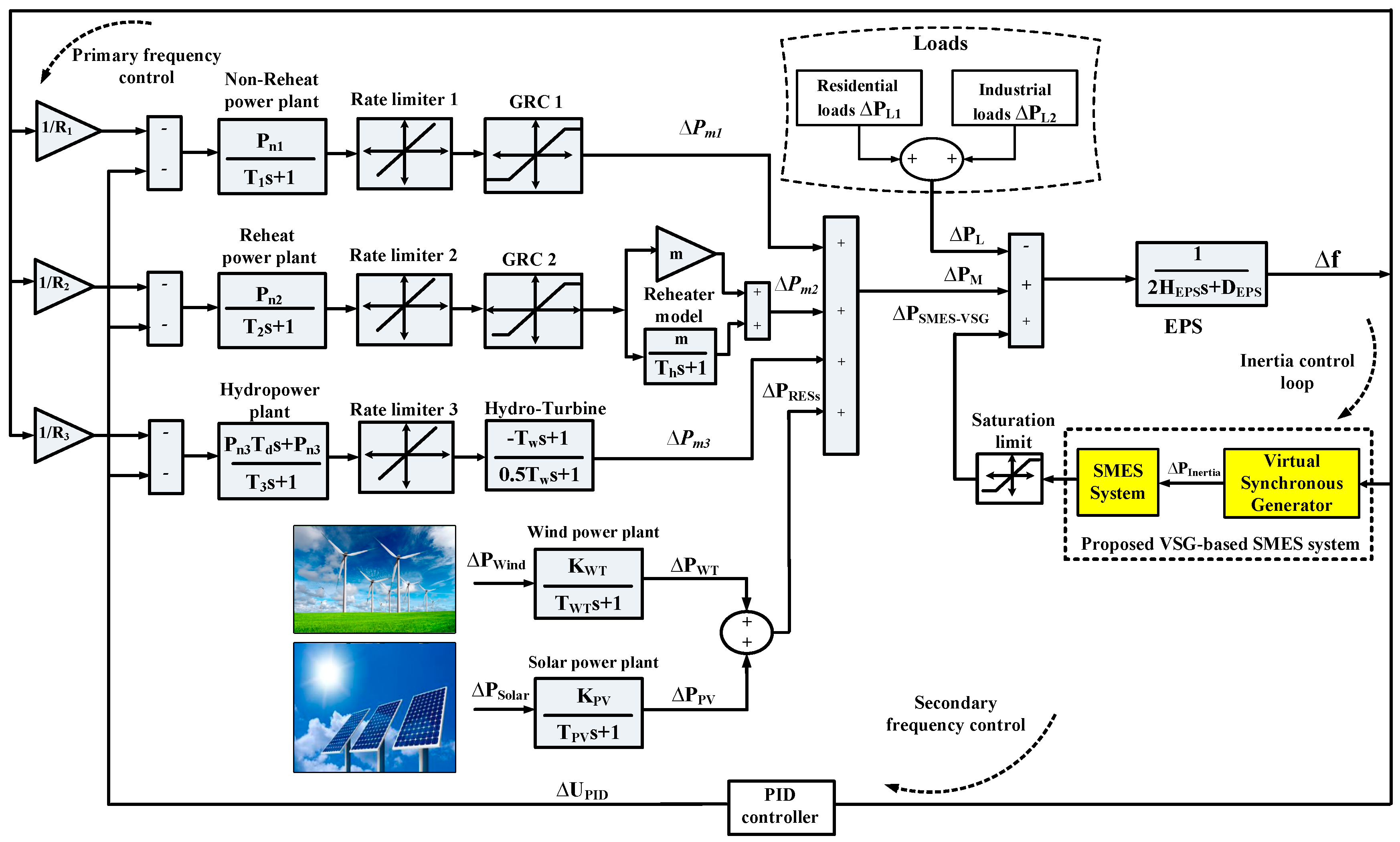
  • To achieve a realistic study on the frequency stability issue for modern power grids, this study is taking into account the effects of several conventional power generation units (e.g., non-reheat, reheat, hydropower plants), in addition to multiple RESs in the analysis of the LFC problem. In other words, the proposed system constitutes a real hybrid power system that keeps pace with the renewable power systems of today.
  • The uncertainties of RESs/loads, system nonlinearities (e.g., generation rate constraint (GRC), and governor deadband (GDB)) are taken into account in the proposed virtual controller design procedure. Thus, the proposed control strategy (i.e., VSG-based SMES) will guarantee avoidance of system instability.
  • Compare the proposed control strategy (i.e., VSG-based SMES) with literature works (i.e., the traditional VSG approach based on battery ESSs) in references [10,12,13,14,15,16,17] to show the feasibility of the proposed system.
This paper is structured as follows. The studied power grid dynamics and modeling is presented in Section 2. Section 3 presents the proposed VSG scheme-based SMES system to increase the frequency stability of modern power grids. The simulation results at different scenarios are presented in Section 4. Finally, Section 5 provides for the conclusion of this work.

2. Modeling and Configuration of the Studied System

The feasibility of the proposed VSG-based SMES system is validated through a real multi-source power system in Egypt, which is considered the test system for the operation plan. The Egypt Power System (EPS) contains both traditional power generation units (i.e., reheat, non-reheat, and hydropower plants) and RESs. The considered RESs contain both the wind power that is generated from Zafarana and Gabel El-Zeit wind farms, and the solar power that is generated from Benban solar park, which is considered one of the world’s largest photovoltaic (PV) plants. As per the Egyptian Electricity Holding Company’s latest 2019 report [26], the total installed capacity and the peak load of the EPS are 58.35 GW and 31.40 GW, respectively. The installed capacity of the generation systems is 53,274 MW for thermal power stations, 2832 MW for hydropower plants, 1127 MW for wind power stations, and 1120 MW for solar farms. Figure 1 shows a simple model of the configuration of the considered EPS with the proposed VSG-based SMES system.
The National Energy Control Center (NECC) in Egypt presented a dynamic model for the LFC of the EPS, as reported in [27]. Therefore, this study simulates this model using MATLAB/Simulink® software with some manipulation to keep pace with future renewable power systems. Figure 2 depicts the dynamic model of the considered EPS with the proposed VSG-based SMES system. In the studied EPS, the conventional power plants are considered manipulation units to control the system frequency. Moreover, the variation of the wind power (ΔPWT), the variation of the solar power (ΔPPV), and the variation of the load power (ΔPL) are regarded as disturbance sources because they are assumed to be time-varying and non-measurable in the simulated system. In this study, the dynamic models of the different components of the power grid are presented with a simplified model (i.e., based on transfer functions) since they are sufficient to analyze the frequency stability in the power systems [28]. The system parameters values are given in Table 1.
To get a precise conception of the system frequency and non-linearity, the physical limitations such as generation rate constraint (GRC) of the turbine unit and the deadband of the governor (GDB) unit are considered [2,29]. In this study, the GRC of the non-reheat turbine is specified at 20% pu/min and the reheat turbine is specified at 10% pu/min. Meanwhile, the GRC of the hydropower turbines can be neglected as its actual value is about 50% pu/min, which is higher than the equivalent generation rate for any real disturbance. For the studied system, the GDB is determined as 0.05% for thermal power generation units (reheat and non-reheat plants) and 0.01% for the hydropower plants. The frequency deviation of the targeted power grid with the frequency control instructions of the primary, secondary, and inertia control units can be obtained as
Δ f = 1 2 H s + D ( Δ P m 1 + Δ P m 2 + Δ P m 3 + Δ P W T + Δ P P V +   Δ P SMES-VSG Δ P L )
where
Δ P m 1 = P n 1 T 1 s + 1 ( 1 R 1 Δ f Δ P c 1 )
Δ P m 2 = ( m + m T h s + 1 ) Δ P g 2  
Δ P g 2 = P n 2 T 2 s + 1 ( 1 R 2 Δ f Δ P c 2 )
Δ P m 3 = ( T w s + 1 0.5 T w s + 1 ) Δ P g 3
Δ P g 3 = P n 3 T d s + P n 3 T 3 s + 1 ( 1 R 3 Δ f Δ P c 3 )
Δ P W T = ( K W T T W T s + 1 ) Δ P Wind
Δ P P V = ( K P V T P V s + 1 ) Δ P Solar .
In which, s is the Laplace operator, Δf is the system frequency fluctuation, H is the system inertia, and D refers to the damping factor. ΔPm1, ΔPm2, and ΔPm3 are the thermal power variation of non-reheat, reheat, and hydropower generation units, respectively. ΔPWT, ΔPPV, and ΔPL are the power change of the wind turbine, PV system, and load power, respectively. ΔPSMES-VSG is the SMES power change based on VSG, which will be discussed in the next section.

3. Design of Virtual Synchronous Generator Based on the SMES System

3.1. Mathematical Model of the SMES Unit

The profile of the generated power from RESs mainly relies on the surrounding environmental conditions, as an example is a PV power that depends on the incident irradiation level and the temperature of the module. Consequently, the power generated from the conventional power plants in the tie-line becomes fluctuated to reserve the load demands at the standard limits while integrating the RESs at a high level. The use of the ESSs can overcome the power fluctuations in the power system to store the extra energy when the RESs provide more power or deliver energy into the system again when the shortage of the RESs power has arisen. In recent years, a lot of the ESSs have been studied with the power system for this purpose such as the battery, supercapacitor, and flywheel. One of the promising types in the ESSs is the SMES, which has received a lot of attention despite the high cost. SMES can provide an unlimited number of the charging/discharging cycles with faster response and has the highest lifetime compared to the other ESSs [30]. These outstanding advantages are considered suited to stabilize the frequency of power grids, especially at the transient instance either of the load or the RESs.
The key element in the SMES system is the magnetic coil, which is fabricated from a special superconducting material that has approximately zero resistance [25]. As long as the SMES coil is reserved in the superconducting state, the zero-energy loss in the SMES coil could be guaranteed, which gives high efficiency. The SMES coil should be cooled at the superconducting temperature by immersing it in the helium vessel. The energy stored in the SMES coil (ESMES) depends on the coil size (L) and the coil current (ISMES) as
E SMES = 1 2 L I SMES 2 .
The SMES coil is interfaced into the power grid at the point of common connection (PCC) through the 12-pulse bridge-based thyristors (i.e., silicon controlled rectifiers (SRCs)) and the transformer as shown in Figure 3. The function of the (Y-Δ)/(Y-Y) transformers is to regulate the voltage into the SMES conversion system based on the SRCs [25]. During the charging and discharging mode of the SMES coil, the bypass thyristors are turned off. On the other hand, when the two bypass thyristors are fired at the same time, the SMES coil operates in the freewheeling state (i.e., the SMES coil does not charge or discharge). The SMES coil should have a closed loop to ensure the coil current is always circulating and to avoid destroying the power devices.
The current of the SMES coil ( I d ) has a unidirectional profile and its value is increased or decreased from the initial current ( I d 0 ) according to the coil status of either charge or discharge. When the voltage around the SMES coil is positive, the SMES coil begins to charge and store the extra energy in the utility grid. On the other hand, the SMES coil discharges when the negative voltage is applied to the coil terminal. The firing angle (α) of the 12-pulse bridge based on the SRCs manages the charge/discharge process of the SMES coil (i.e., generate positive/negative voltage across the coil). The relation between the voltage applied to the SMES coil ( E d ) and the firing angle (α) can be expressed as
E d = 2 V d 0 c o s   α 2 I d R D
where V d 0 is the maximum circuit bridge voltage (in kV), I d is the SMES coil current (in kA), and R D is the damping resistance (in kΩ).
Based on (10), when the firing angle (α) is larger than 90°, the average voltage of the SMES is positive and thus the SMES coil starts to charge. Otherwise, at the firing angle (α) less than 90°, the average voltage of the SMES coil is negative and the SMES coil is discharging.
The SMES system is used as an auxiliary LFC to stabilize the system frequency despite the different disturbances. The complete block diagram to represent the SMES system in the studied LFC model is displayed in Figure 4. The frequency fluctuation generates the perturbation of the coil current ( K SMES 1 · Δ f ) . Also, the current deviation of the SMES coil ( Δ I d ) is utilized as a negative feedback signal (Kf) to be added with perturbation current [21]. The deviation of voltage across the SMES coil (ΔEd) and the deviation current (ΔId) can be expressed as in Equations (11) and (12), respectively.
Δ E d = 1 1 + s T c ( K SMES 1   . Δ f K f Δ I d )
Δ I d = Δ E d s L
where K SMES 1 is the control gain of the SMES loop, and Tc is the converter time constant.
The total SMES coil current is ( Δ I d + I d 0 ), and thus the perturbation in the power of the SMES systems can be given as
Δ P SMES = Δ E d ( Δ I d + I d 0 ) .
In this study, the utilized parameters of the SMES unit are listed in Table 2. Even when system inertia is reduced by 80% of its nominal value, these parameters give better dynamic stability during transients.

3.2. Modeling of VSG-Based SMES System

The VSG is proposed to mimic the characteristics of a real synchronous generator in the power grid through the virtual rotor concept (i.e., which emulates the properties of inertia and damping) and virtual control loops (i.e., which emulate the conventional frequency control loops) as shown in Figure 5. The behavior of the rotating dynamics of real synchronous machines can be described by the swing equation given in (14) and the power reference (Pref) for the virtual rotor can be obtained as in (15) [10].
Δ P M ( s ) Δ P L ( s ) = ( 2 H s + D )   Δ f ( s )
P r e f = ( H i s + D i ) Δ f
where ΔPM is the change of the mechanical power, Hi is the virtual rotor inertia, and Di is the virtual rotor damping.
The ESS is needed to emulate the inertia power and damping properties required by the power system. Due to the attractive properties of SMES, such as unlimited numbers of charging/discharging cycles, fast response, and high efficiency [20], this paper proposes a new VSG scheme based on the SMES system to increase the frequency stability of a low-inertia power grid as displayed in Figure 5. Technically speaking, the frequency control loops in the traditional power grids can be classified into primary and secondary, and the synchronous generator uses the turbine governor as the primary control to adjust the system frequency [10]. The droop control is typically utilized in the power system to sustain the system frequency at the permitted range by controlling the turbine power. Moreover, in large power systems, the LFC is utilized to sustain the system frequency at its standard value for a period ranging from a few seconds to a few minutes after the system disturbance [12]. Consequently, similar primary and secondary frequency controllers can be constructed for the VSG as a droop controller and integral controller, respectively. Thus, the virtual primary and secondary controls (shown in Figure 5) are combined representing the proportional-integral (PI) controller and the output power from the virtual control loops ( Δ P P I ) can be expressed as
Δ P P I = ( 1 R i   + K i s ) Δ f
where R i is a virtual droop characteristic and K i is a virtual secondary integrator gain.
To replicate the realistic power response of the SMES system, the limiter block is set to limit the maximum/minimum power capacity of SMES. The power capacity limit of the SMES system has been selected at ±0.2 pu.

3.3. Design of Virtual Controller for VSG-Based SMES System

From Figure 5, the proposed control strategy relies on the virtual controller (i.e., PI controller), which is a combination of the virtual primary controller (i.e., P controller) and virtual secondary controller (i.e., I controller). The virtual controller transfer function can be obtained as
G c ( s ) = 1 R i   + K i s
Considering the key advantages of the particle swarm optimization (PSO) method are high convergence rates, ease of application, and minimum storage requirements [10,31], the PSO method is applied to find the optimal parameters of the virtual controller of the proposed VSG-based SMES system. The integral of squared error (ISE) is utilized as the fitness function for the considered optimization method (i.e., PSO algorithm) and can be expressed as [10]
I S E =   0 t s i m ( Δ f ) 2 d t
where t sim denotes the simulation time.
The gains constraints of the proposed virtual controller are
R i m i n R i R i max   K i m i n K i K i max  
where R i m i n , K i m i n , R i max   , and K i max are the minimum and the maximum values of the virtual primary and secondary controller parameters, respectively. The range of the virtual secondary controller gain is selected as (0–2) and the virtual droop characteristic is bounded in the range (1–10).
The key target of the PSO method is to reach the minimum value of the fitness function given in (18) and use the corresponding optimized parameters with the proposed virtual inertia control. Kennedy and Eberhart have been presenting the PSO algorithm since 1995 [32]. It is considered one of the strategies for evolutionary computation. PSO’s fundamental concept relies on a group of flocking birds that have either been dispersed or are in groups looking for food from one location to another. One can find where food has been located as the information is transferred by other birds during the food search [33]. Individuals called particles are used in this optimization process, instead of using evolutionary operators. In this manner, a flock comprises many particles, each particle indicating the problem’s potential. In this optimization algorithm, every particle flies through the search space according to its own unique flying experience and the flying history of its mates. In the D-dimension search space, each particle is transacted as a single particle. The particle location defined as xi, the previous best mode of any particle is reported and referred to as Pbest. While the overall best value is gbest and a global version of the considered optimization algorithm follows [31]. The particle i velocity is denoted by vi, and the speed and position of all particles are updated every iteration as
v i n + 1 = w v i n + c 1 r a n d ( ) ( P i n x i n ) + c 2 r a n d ( ) ( P g n x i n )
x i n + 1 = x i n + v i n + 1
In which, n describes the iteration number, r a n d ( ) is a random function, Pi is the Pbest of the particle i at iteration n, w denotes to the inertia weight factor, Pg is the gbest of particle i at iteration n, and c1, c2 are the acceleration constants.
These formulas are utilized to reflect the recent position and velocity values for each particle, taking the past values into account. The optimization algorithm’s learning factors have important consequences for the convergence rate. For more information on the PSO algorithm, refer to [31,32,33]. In this study, the key purpose of the PSO method is to mitigate the system frequency fluctuation by determining the optimal values of the virtual controller gains. The PSO code is executed using the MATLAB software. The procedures of the PSO method to fine-tune the virtual controller gains (i.e., Ri, and Ki) is outlined in Algorithm 1, and the initial settings of the PSO algorithm are listed in Table 3. Consequently, the proposed VSG model parameters under the system operation are obtained in Table 4. These parameters will generate the optimal control signal to the SMES system to supply/absorb electrical power to/from the power grid with a fast response and low steady-state error.
Algorithm 1. Particle swarm optimization (PSO) algorithm.
1Set dimension d = 2 (i.e., Ri and Ki)
2fori = 1: s
3forj = 1: d
4Setxi,d = Rand(dmin,dmax)
5Setvi,d = Rand(vmin,vmax)
6end for
7SetPbest = xi
8iff(Pbest) < f(gbest) then
9Setgbest = Pbest
10end if
11end for
12fort = 1: n
13fori = 1: s
14iff(xi) < f(Pbest) then
15SetPbest = xi
16end if
17iff(Pbest) < f(gbest) then
18Setgbest = Pbest
19end if
20end for
21Update the particle’s velocity using (20)
22Update the particle’s position using (21)
23iff(gbest) < 0.001
24break
25else
26continue
27end if
28end for

4. Simulation Results and Discussion

The simulation results of the considered renewable power system (i.e., EPS) are implemented under various load/RES perturbations using MATLAB/Simulink® software to check the superiority and efficacy of the proposed VSG based on the SMES system. Furthermore, the efficacy of the proposed VSG based on the SMES system in low-inertia power grids is validated by comparing its performance with that traditional VSG approach based on battery ESS in references [10,12,13,14,15,16,17]. In this work, the battery ESS was mathematically modeled by a first-order transfer function of a time constant of 10 s and a unity gain, and the same power constraints of the SMES system mentioned in Section 3.1 are used with the battery ESS system. The studied EPS comprises both conventional power plants (e.g., steam, gas, and hydropower plants) and RESs as shown in Figure 2. Besides which, the uncertainties of RESs/loads, system nonlinearities (e.g., GRC and GDB) are considered in designing the proposed VSG based on the SMES system. Preservation of the frequency stability of the considered low-inertia power grid is verified through the following scenarios at different operating conditions.

4.1. Scenario 1: System Performance Evaluation under Low RESs Penetration and Heavy Load Change

The key goal of this scenario is to investigate the reliability of the studied EPS with the proposed VSG based on the SMES system, considering RES penetration levels, nonlinearities, and uncertainties. The targeted power system is examined in the presence of wind power fluctuation at time t = 500 s and solar power fluctuations at time t = 0 s as shown in Figure 6, and the combined power variation of RESs, in this case, is considered lightly penetrated. Also, the total load comprises the residential and industrial loads, and the loading value is set at the heavy state (i.e., approximately at peak of 0.6 pu) as shown in Figure 7. Furthermore, the considered power grid with the proposed VSG-based SMES is examined in conditions of 100% of system inertia (i.e., high system inertia), 60% of system inertia (i.e., medium system inertia), and 20% of system inertia (i.e., low system inertia). Figure 8 displays the frequency response of the studied power grid under low RES penetration and heavy random loads in conditions of 100%, 60%, and 20% of system inertia, respectively. It is clear from Figure 8 that, in all the cases tested, the considered power grid with the proposed VSG-based SMES is more robust and faster than the traditional VSG design based on battery ESS; whereas, the considered power grid with the proposed VSG design based on the SMES system gives a small frequency deviation when the load is highly changed at t = 300 s and t = 1000 s. Therefore, the best performance of the system frequency is achieved by applying the proposed VSG design based on the SMES system, which in the circumstances of 100%, 60%, and 20% of system inertia will sustain the system frequency deviation within ±0.03 Hz. The performance specification of the considered power grid; maximum settling time (Ts), maximum undershoot (MUS), and maximum overshoot (MOS) with the proposed VSG design based on the SMES system and the traditional VSG design based on battery ESSs for this scenario are given in Table 5.

4.2. Scenario 2: System Performance Evaluation under High RES Penetration and Heavy Load Change

In this scenario, a high-share RES penetration is used to test the proposed VSG shown in Figure 9. Besides, the same heavy random load in scenario 1 is used (Figure 7). The comparison is made under conditions of 100% of system inertia (i.e., high system inertia), 60% of system inertia (i.e., medium system inertia), and 20% of system inertia (i.e., low system inertia). Figure 10 displays the frequency response of the studied power grid with the proposed VSG design based on the SMES system under high-share RES penetration and heavy random loads in conditions of 100%, 60%, and 20% of system inertia, respectively. From the obtained results, the proposed control strategy based on the SMES system significantly improves the performance of system frequency and gives a low system transient magnitude compared to the traditional design that depends on battery ESSs in low-inertia power grids. On the other hand, the studied EPS with the traditional VSG design based on battery ESSs is oscillating with large frequency deviations resulting from the severe shortage in the system inertia. Despite the low-inertia coefficient, the proposed VSG design based on the SMES system can preserve the frequency stability of the low-inertia power grid considering renewables. The studied power grid performance specifications; MOS, MUS, and Ts with the proposed VSG design based on the SMES system and the traditional VSG design based on battery ESSs during this scenario are given in Table 6.

5. Conclusions

A new VSG design based on the SMES system has been proposed to increase the frequency stability of low-inertia power grids, considering high-share RES penetration, nonlinearities, and uncertainties. The concept of the proposed VSG relies on emulating the characteristics of the real synchronous generator through the virtual rotor concept (i.e., which emulates the properties of inertia and damping) and the virtual control loops concept (i.e., which emulate the conventional frequency control loops). Moreover, the ESS is needed to mimic the inertia power and damping properties required from the VSG. Due to the attractive properties of SMES such as an unlimited number of charging/discharging cycles, fast response, and high efficiency, this paper proposed the VSG design based on the SMES system. This paper presented the EPS as a test system, which comprises both conventional power generation units (e.g., non-reheat, reheat, hydropower plants) and RESs. Also, the uncertainties of RESs/loads and system nonlinearities (e.g., GRC and GDB) are considered in designing the proposed VSG based on the SMES system. The efficacy of the proposed VSG design based on the SMES system has been confirmed by comparing its performance with the traditional VSG design based on the battery ESS under conditions of 100%, 60%, and 20% of the system inertia. From the obtained results, the proposed VSG design based on the SMES system improves system stability.

Author Contributions

Conceptualization, G.M.; methodology, G.M. and A.B.; software, G.M. and M.N.; validation, A.B., M.N. and E.P.; formal analysis, G.M. and A.B.; investigation, G.M.; resources, E.P.; data curation, M.N.; writing—original draft preparation, G.M.; writing—review and editing, A.B. and E.P.; visualization, A.B. and M.N.; supervision, E.P.; project administration, E.P.; funding acquisition, E.P. All authors have read and agreed to the published version of the manuscript.

Funding

This work was supported by the Estonian Research Council grant PRG658.

Conflicts of Interest

The authors declare no conflict of interest.

References

  1. Yan, R.; Masood, N.-A.; Saha, T.K.; Bai, F.; Gu, H. The anatomy of the 2016 south australia blackout: A catastrophic event in a high renewable network. IEEE Trans. Power Syst. 2018, 33, 5374–5388. [Google Scholar] [CrossRef]
  2. Bevrani, H. Robust Power System Control; Springer: New York, NY, USA, 2014. [Google Scholar]
  3. Hasanien, H.M. Whale optimisation algorithm for automatic generation control of interconnected modern power systems including renewable energy sources. IET Gener. Transm. Distrib. 2018, 12, 607–614. [Google Scholar] [CrossRef]
  4. Khooban, M.H.; Gheisarnejad, M. A novel deep reinforcement learning controller based type-ii fuzzy system: Frequency regulation in microgrids. IEEE Trans. Emerg. Top. Comput. Intell. 2020, 1–11. [Google Scholar] [CrossRef]
  5. Xu, D.-Z.; Liu, J.; Yan, X.-G.; Yan, W. A novel adaptive neural network constrained control for a multi-area interconnected power system with hybrid energy storage. IEEE Trans. Ind. Electron. 2017, 65, 6625–6634. [Google Scholar] [CrossRef]
  6. Eshetu, W.; Sharma, P.; Sharma, C. ANFIS based load frequency control in an isolated micro grid. In Proceedings of the IEEE International Conference on Industrial Technology (ICIT), Lyon, France, 19–22 February 2018; pp. 1165–1170. [Google Scholar]
  7. Ma, M.; Liu, X.; Zhang, C. LFC for multi-area interconnected power system concerning wind turbines based on DMPC. IET Gener. Transm. Distrib. 2017, 11, 2689–2696. [Google Scholar] [CrossRef]
  8. Bevrani, H.; Feizi, M.R.; Ataee, S. Robust frequency control in an islanded microgrid: H∞ and μ-synthesis approaches. IEEE Trans. Smart Grid 2015, 7, 1. [Google Scholar] [CrossRef] [Green Version]
  9. Saxena, P.; Singh, N.; Pandey, A.K. Enhancing the dynamic performance of microgrid using derivative controlled solar and energy storage based virtual inertia system. J. Energy Storage 2020, 31, 101613. [Google Scholar] [CrossRef]
  10. Magdy, G.; Shabib, G.; Elbaset, A.A.; Mitani, Y. Renewable power systems dynamic security using a new coordination of frequency control strategy based on virtual synchronous generator and digital frequency protection. Int. J. Electr. Power Energy Syst. 2019, 109, 351–368. [Google Scholar] [CrossRef]
  11. Teimourzadeh, S.; Aminifar, F.; Davarpanah, M. Microgrid dynamic security: Challenges, solutions and key considerations. Electr. J. 2017, 30, 43–51. [Google Scholar] [CrossRef]
  12. Fathi, A.; Shafiee, Q.; Bevrani, H. Robust frequency control of microgrids using an extended virtual synchronous generator. IEEE Trans. Power Syst. 2018, 33, 6289–6297. [Google Scholar] [CrossRef]
  13. Magdy, G.; Shabib, G.; Elbaset, A.A.; Mitani, Y. A novel coordination scheme of virtual inertia control and digital protection for microgrid dynamic security considering high renewable energy penetration. IET Renew. Power Gener. 2019, 13, 462–474. [Google Scholar] [CrossRef]
  14. Sockeel, N.; Gafford, J.; Papari, B.; Mazzola, M. Virtual Inertia Emulator-Based Model Predictive Control for Grid Frequency Regulation Considering High Penetration of Inverter-based Energy Storage System. IEEE Trans. Sustain. Energy 2020, 11, 2932–2939. [Google Scholar] [CrossRef]
  15. Kerdphol, T.; Rahman, F.S.; Mitani, Y.; Watanabe, M.; Kufeoglu, S. Robust virtual inertia control of an islanded microgrid considering high penetration of renewable energy. IEEE Access 2017, 6, 625–636. [Google Scholar] [CrossRef]
  16. Ali, H.; Magdy, G.; Li, B.; Shabib, G.; Elbaset, A.A.; Xu, D.; Mitani, Y. A new frequency control strategy in an islanded microgrid using virtual inertia control-based coefficient diagram method. IEEE Access 2019, 7, 16979–16990. [Google Scholar] [CrossRef]
  17. Kerdphol, T.; Watanabe, M.; Hongesombut, K.; Mitani, Y. Self-adaptive virtual inertia control-based fuzzy logic to improve frequency stability of microgrid with high renewable penetration. IEEE Access 2019, 7, 76071–76083. [Google Scholar] [CrossRef]
  18. Bevrani, H.; Ise, T.; Miura, Y. Virtual synchronous generators: A survey and new perspectives. Int. J. Electr. Power Energy Syst. 2014, 54, 244–254. [Google Scholar] [CrossRef]
  19. D’Arco, S.; Suul, J.A.W.; Fosso, O.B. A Virtual Synchronous Machine implementation for distributed control of power converters in SmartGrids. Electr. Power Syst. Res. 2015, 122, 180–197. [Google Scholar] [CrossRef]
  20. Muttaqi, K.M.; Islam, R.; Sutanto, D. Future power distribution grids: Integration of renewable energy, energy storage, electric vehicles, superconductor, and magnetic bus. IEEE Trans. Appl. Supercond. 2019, 29, 1–5. [Google Scholar] [CrossRef] [Green Version]
  21. Khosraviani, M.; Jahanshahi, M.; Farahani, M.; Bidaki, A.R.Z. Load–Frequency Control Using Multi-objective Genetic Algorithm and Hybrid Sliding Mode Control-Based SMES. Int. J. Fuzzy Syst. 2017, 20, 280–294. [Google Scholar] [CrossRef]
  22. Pappachen, A.; Fathima, A.P. Load frequency control in deregulated power system integrated with SMES–TCPS combination using ANFIS controller. Int. J. Electr. Power Energy Syst. 2016, 82, 519–534. [Google Scholar] [CrossRef]
  23. Ngamroo, I.; Karaipoom, T. Improving low-voltage ride-through performance and alleviating power fluctuation of DFIG wind turbine in DC microgrid by optimal SMES with fault current limiting function. IEEE Trans. Appl. Supercond. 2014, 24, 1–5. [Google Scholar] [CrossRef]
  24. Said, S.M.; Aly, M.; Hartmann, B.; Alharbi, A.G.; Ahmed, E.M. SMES-based fuzzy logic approach for enhancing the reliability of microgrids equipped with PV generators. IEEE Access 2019, 7, 92059–92069. [Google Scholar] [CrossRef]
  25. Padhan, S.; Sahu, R.K.; Panda, S. Automatic generation control with thyristor controlled series compensator including superconducting magnetic energy storage units. Ain Shams Eng. J. 2014, 5, 759–774. [Google Scholar] [CrossRef] [Green Version]
  26. Egyptian Electricity Holding Company, Annual Report 2019. Available online: http://www.moee.gov.eg/english_new/report.aspx (accessed on 1 September 2020).
  27. Magdy, G.; Bakeer, A.; Shabib, G.; Elbaset, A.A.; Mitani, Y. Decentralized model predictive control strategy of a realistic multi power system automatic generation control. In Proceedings of the 2017 Nineteenth International Middle East Power Systems Conference (MEPCON), Menoufia, Egypt, 19–21 December 2017; pp. 190–196. [Google Scholar]
  28. Lee, D.-J.; Wang, L. Small-signal stability analysis of an autonomous hybrid renewable energy power generation/energy storage system part I: Time-domain simulations. IEEE Trans. Energy Convers. 2008, 23, 311–320. [Google Scholar] [CrossRef]
  29. Kundur, P. Power System Stability and Control; McGraw-Hill Press: New York, NY, USA, 1994. [Google Scholar]
  30. Amrouche, S.O.; Rekioua, D.; Bacha, S. Overview of energy storage in renewable energy systems. Int. J. Hydrog. Energy 2016, 41, 20914–20927. [Google Scholar] [CrossRef]
  31. Kerdphol, T.; Qudaih, Y.; Mitani, Y. Optimum battery energy storage system using PSO considering dynamic demand response for microgrids. Int. J. Electr. Power Energy Syst. 2016, 83, 58–66. [Google Scholar] [CrossRef]
  32. Kennedy, J.; Eberhart, R.C. Particle swarm optimization. Proc. IEEE Int. Conf. Neural Netw. 1995, 4, 1942–1948. [Google Scholar]
  33. Ang, K.H.; Chong, G.; Li, Y. PID control system analysis, design, and technology. IEEE Trans. Control. Syst. Technol. 2005, 13, 559–576. [Google Scholar] [CrossRef] [Green Version]
Figure 1. A simplified model of the studied system with the proposed virtual synchronous generator (VSG)-based superconducting magnetic energy storage (SMES) system.
Energies 13 05641 g001
Figure 2. A dynamic model of the studied power system with the proposed VSG-based SMES system.
Energies 13 05641 g002
Figure 3. Configuration of the SMES conversion system with the power system.
Energies 13 05641 g003
Figure 4. Dynamic model of the SMES system for the load frequency control (LFC) study.
Energies 13 05641 g004
Figure 5. Dynamic model of the proposed VSG-based SMES system.
Energies 13 05641 g005
Figure 6. Low penetration of renewable energy sources (RESs): (a) wind power and (b) solar power.
Energies 13 05641 g006aEnergies 13 05641 g006b
Figure 7. Combination of residential and industrial loads (i.e., random load).
Energies 13 05641 g007
Figure 8. Frequency response of the studied system under low RES penetration: (a) high system inertia, (b) medium system inertia, and (c) low system inertia.
Energies 13 05641 g008aEnergies 13 05641 g008b
Figure 9. High penetration of RESs: (a) wind power and (b) solar power.
Energies 13 05641 g009
Figure 10. Frequency response of the studied system under high RES penetration: (a) high system inertia, (b) medium system inertia, and (c) low system inertia.
Energies 13 05641 g010
Table 1. Parameters of the targeted power grid based on the Egypt Power System (EPS).
TermDescriptionValue
HEquivalent inertia constant (pu)5.710
DSystem damping coefficient of the area (pu)0.028
T1Valve time constant of the non-reheat plant (s)0.400
T2Steam valve time constant of reheat plant (s)0.400
T3Water valve time constant hydro plant (s)90.000
TdDashpot time constant of hydro plant speed governor (s)5.000
ThThe time constant of reheat thermal plant (s)6.000
TwWater starting time in hydro intake (s)1.000
mThe fraction of turbine power (intermediate pressure section)0.500
R1Governor speed regulation non-reheat plant (pu)2.500
R2Governor speed regulation reheat plant (pu)2.500
R3Governor speed regulation hydro plant (pu)1.000
Pn1Nominal rated Power output for the non-reheat plant (pu)0.253
Pn2Nominal rated Power output for reheat plant (pu)0.611
Pn3Nominal rated Power output for the hydro plant (pu)0.136
fBase of the system frequency (Hz)50.000
TPVTime constant of the PV system (s)1.850
KPVGain constant of the PV system1.000
TWTTime constant of wind turbines (s)1.500
KWTGain constant of wind turbines1.000
KPProporational gain of the PID cotroller 71.253
KIIntegral gain of the PID cotroller5.905
KDDerivative gain of the PID cotroller6.107
Table 2. Parameters of the studied SMES system [21].
TermDescriptionValue
Id0Inductor rated current (kA)20.000
TcConverter time constant (s)0.030
KfFeedback gain of ( Δ I d )0.001
KSMES-1Control gain of the SMES loop1.000
LCoil inductance (H)3.000
Table 3. Parameters of the particle swarm optimization (PSO) algorithm.
TermDescriptionValue
sSize of the swarm (i.e., no of birds)50.000
nNumber of iterations 50.000
wInertia weight factor0.950
c1Acceleration constant 10.120
c2Acceleration constant 22.000
Table 4. VSG parameters values.
TermDescriptionValue
HiVirtual inertia (pu s)0.900
DiVirtual damping (pu MW/Hz)10.400
R i Virtual droop characteristic (Hz/pu MW)5.000
K i Virtual secondary integrator gain0.002
Table 5. The performance specification of the considered system for scenario 1.
Scenario 1
(Low RESs)
VSG-Based BatteryProposed VSG-Based SMES
MUS (pu)MOS (pu)TS (s)MUS (pu)MOS (pu)TS (s)
High system inertia (100%)0.0390.033150.000.0080.0043.100
Medium system inertia (60%)0.0500.048152.000.0120.0053.000
Low system inertia (20%)0.0810.075156.000.0310.0052.500
Table 6. The performance specification of the considered system for scenario 2.
Scenario 2
(High RESs)
VSG-Based BatteryProposed VSG-Based SMES
MUS (pu)MOS (pu)TS (s)MUS (pu)MOS (pu)TS (s)
High system inertia (100%)0.0360.04347.0000.0070.0152.600
Medium system inertia (60%)0.0500.06151.0000.0100.0265.800
Low system inertia (20%)0.0830.10562.0000.0310.0736.100
Publisher’s Note: MDPI stays neutral with regard to jurisdictional claims in published maps and institutional affiliations.

