A Thermodynamic Analysis of Heavy Hydrocarbons Reforming for Solid Oxide Fuel Cell Application as a Part of Hybrid Energy Systems


Department of Fundamental Research in Energy Engineering, Faculty of Energy and Fuels, AGH University of Science and Technology, 30-059 Krakow, Poland
*
Author to whom correspondence should be addressed.
Energies 2021, 14(2), 337; https://0-doi-org.brum.beds.ac.uk/10.3390/en14020337
Submission received: 3 December 2020
/
Revised: 4 January 2021
/
Accepted: 6 January 2021
/
Published: 9 January 2021
(This article belongs to the Special Issue Computer Simulation of Hybrid Energy System)
Abstract
:A thermodynamical analysis of steam reforming of Associated Petroleum Gas (APG) was conducted in the presented research. The reforming process of heavy hydrocarbons for small scale power generation is a complex issue. One of the main issues is that a set of undesired chemical reactions deposit solid carbon and, consequently, block the reactor’s catalytic property. The experimental investigation is crucial to design an APG reforming reactor. However, a numerical simulation is a key tool to design a safe operating condition. Designing the next generation of reactors requires a complex coupling of mathematical models, kinetics, and thermodynamic analysis. In practice, the thermodynamic analysis should be applied in each control volume to assure realistic results. This is not easy to apply in practice since both thermodynamic analysis and CFD modeling can be time-consuming. In this paper, the authors suggest using a mathematical formalism called Parametric Equation Formalism to calculate the equilibrium composition. The novelty lies in the mathematical approach in which any complex system at equilibrium can be reduced to the problem of solving one non-linear equation at a time. This approach allows implementing a thermodynamic analysis easily into CFD models to assure the reasonability of obtained results and can be used for research and development of solid oxide fuel cells as a part of hybrid energy systems.
1. Introduction
Associated Petroleum Gas (APG, hereafter) is a form of natural gas that contains hydrocarbons heavier than methane. Typically, its contains 50–70% of methane (CH), 5–10% of ethane (CH), 5–15% propane (CH), 1–10% butane (CH), 1–10% of carbon dioxide (CO) and 1–10% of nitrogen (N). According to the report elaborated under the auspices of the European Bank for Reconstruction and Development, 20 billion cubic meters per year of associated gas is simply flared in main APG producing countries such as Russia, Kazakhstan, Turkmenistan, and Azerbaijan [1]. For the targeted countries flaring remains at 24–30% of total APG production. The number is even grated in the scale of the entire World, where 150 billion cubic meters of associated gas is flared. This gives an economic loss of approximately 30.6 billion dollars. The cost does not include environmental impacts, which might be significant since flaring is responsible for 400 million tons in CO emissions. This makes APG flaring a significant producer of greenhouse gases and make it responsible for about 2% of total global CO emission. On the other hand, instead of flaring the gas, it can be used more productively. Fuel cells might help to use associated gas at the spot to provide electricity for the refinery and obey the necessity to send gas via pipelines. Another example that increases fuel cell application potential is a hybrid energy system consisting of renewable energy sources and fuel cells [2,3]. Hydrogen is the primary fuel [4] for Solid Oxide Fuel Cells (SOFC) but is not the only one that can be oxidized, and an example can be carbon monoxide [5]. The steam reforming process of gaseous fuels rich in hydrocarbons can produce syngas—a gas that contains hydrogen and carbon monoxide in various concentrations. A simplified representation of the heavy hydrocarbons reforming process can be written as follows:
Previous articles state that ethane can also be a substrate for the steam reforming process [6,7] and can be used together with other higher hydrocarbons as fuel for SOFC [8,9]. Promising results were obtained by non-thermal plasma steam reforming. The method allows for obtaining great purity hydrogen from heavy hydrocarbons and avoids CO and CO production. In the plasma process, carbon deposit on the reactor walls and on electrodes is a serious problem decreasing the system efficiency [10,11]. This is also the main problem during the conventional reforming process of hydrocarbons. In the literature, several publications about carbon deposition formation in reforming processes can be found, for example, during steam reforming [12], steam reforming of methanol [13], carbon dioxide reforming [14,15], reforming of biogas [16], and gasoline reforming [17]. Furthermore, there is a lack of information in the literature regarding carbon deposition formation during the reforming process of APG. This paper aims to enrich the description of the associated gas reforming process by presenting a thermodynamic analysis and thus fill this gap in the literature. An alternative model approach called Parametric Equation Formalism is introduced. In the past, formalism has been used to investigate the metallurgical processes [18,19,20] and steam/dry reforming of methane [12,15]. The modeling of the steam reforming process of methane and ethane have been presented in these two articles [21,22]. In this publication, the authors want to present a new implementation of the mentioned approach to a more complex system of six different chemical reactions. Thus, this is the first paper known to the authors using this formalism to analyze the APG reforming system. It is hard to find many publications regarding the modeling of the heavy hydrocarbons reforming process because of its complex nature from the mathematical point of view. There are some publications, but the authors are focused on steam reforming of APG to methane-rich gas [23,24,25]. Other researchers are analyzing steam reforming of propane only [26,27,28]. The mathematical modes they are using are usually based on chemical kinetics, the Gibbs free energy minimization method, genetic algorithm, and chemical kinetics models with heat and mass transfer. The first one requires experimental data, the second—with other optimization procedures, are generally complicated and time-consuming. The last one is usually done by commercial software packages. There are other methods, such as the Numerical Jacobian Approach (a system of non-linear equations has to be solved) [21] and Computational Fluid Dynamics [22,29]. Unfortunately, all of the procedures mentioned above have several drawbacks. They are complex, time-consuming, often require commercial tools to get a solution. The chemical kinetics models describe only the analyzing case, and because of that, it is not easy to point out some overall conclusions. The Parametric Equation Formalism is based on the thermodynamic equilibrium. Therefore the limitations of the analyzed process will always be universal and clear to see. To summarize, the possibility and potential of the presented formalism extend beyond the reforming system and can be adapted to any complex system’s equilibrium characteristic.
2. Thermodynamic Model
A standard steam reforming process is defined by the steam methane reforming reaction, dry reforming reaction, and water-gas shift reaction, respectively [30,31,32,33,34,35]:
when the fuel mixture contains hydrocarbons heavier than methane, an additional reaction has to be used:
The reaction (5) is strongly endothermic, and almost all the reactants are consumed [17]. The carbon dioxide methanation reaction accomplishes reaction (5) in analyzing range of temperatures:
Hydrocarbons heavier than methane are reformed to methane through methanation process, as expressed below [8,9]:
The equilibrium constants of reactions (2)–(4) and (7) are defined as follows:
where , , , , and are the changes in the standard Gibbs free energy of, respectively, the methane/steam reforming, dry reforming, shift reaction and methanation [J mol], R is the universal gas constant 8.314482 [J mol K], and T [K] is the reaction temperature. To create a full model of the reforming process besides reactions (2)–(4) and (7) also carbon deposition formation has to be taken into account in the analysis. At a particular pressure and temperature, all of the gas mixture substances (CH, HO, CO, CO, H) reach thermodynamic equilibrium. In these conditions, two reactions are the source of carbon formation, methane cracking, and Boudouard reaction, defined as follows [36]:
The gas mixture’s final composition in the reforming process consists of (CO/CO) and (H/CH). Therefore the equilibrium in reactions (17) and (18) is shifted towards the carbon deposition formation. The possibility of carbon formation can be defied by parameter , together with the assumption that activities of pure substances are equal to one [13,14,15]:
The carbon formation occurs when the parameter is greater than 1. There is no equilibrium in the system, and reactions (17) and (18) are shifted towards the products’ side. When = 1, the reactions are in equilibrium, and for below 1, carbon deposition formation is impossible thermodynamically. The parameters which define carbon chemical activity are and . They are within the range from 0 to 1, where 1 indicates carbon in the solid form.
3. Characteristic Equation Formalism
The formalism was first introduced and developed in the Department of Fundamental Research in Energy Engineering, AGH University of Science and Technology [12,15,18,19,20]. The basic postulates of the parametric equation used in the calculations are presented below. The formalism assumed that the following equation could describe any chemical reaction:
where: s is a number of reagents, is reactant i, is stoichiometric coefficient of reactant i, adopts positive values for the products of the reaction and negative values for the subtracts. If a chemical species is present in the system but does not participate in the considered chemical reaction, then is equal to zero. When the conditions in the system can be assumed isothermal-isobaric, the transition of reacting gas phase can be represented by a vector with the characteristic equation presented below:
where and are equilibrium and inlet molar fraction of gas component i, is direction angle. Direction cosine of a line can be expressed as follows:
For a non-equimolar reaction () product the transition of reacting gas phase can be represented by the following equation:
where is a characteristic point of a reaction and is defined as:
For an equimolar reaction () product the transition of reacting gas phase can be represented by the following equation:
Table 1 shows the characteristic equation of equilibrium molar fraction for each substance in the process.
4. Computation Procedure
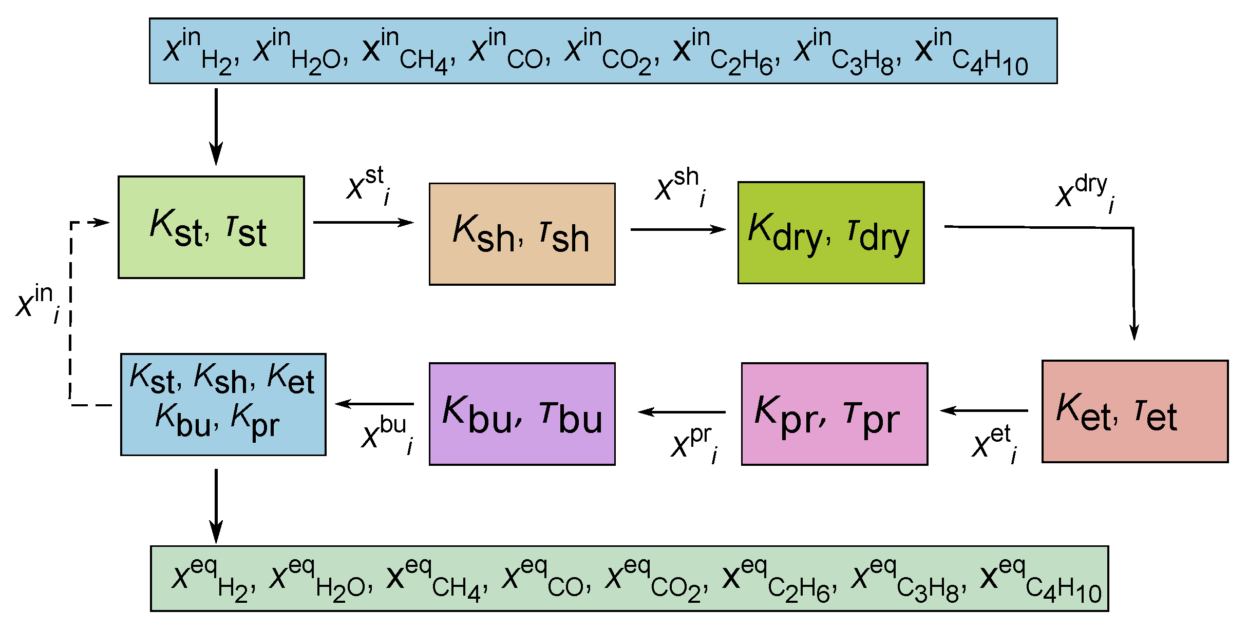
The parametric equation method was implemented and solved by an in-house script written in MATLAB (The MathWorks, Inc., USA). Figure 1 schematically presents the flow of computation procedure. First, the transition of reactants from the initial state (Table 2) into the equilibrium state of methane-steam reforming can be calculated as the vector described by the parametric equation and listed in second column in Table 1. Equilibrium state of methane steam reforming treated separately (Reaction (4)) is considered as input parameters to dry reforming reaction . Consequently, the final composition of dry reforming becomes an initial condition for shift reaction (4). The procedure is iteratively repeated for all reaction considered in the system (Reactions (2)–(4) and (8)–(10)) until each equilibrium constant is satisfied. The convergence is reached when the imbalance for each equilibrium constant is less than . From the numerical point of view, only one non-linear equation (polynomial) must be solved for each reaction. In the case of more than one reaction, this can be done iteratively, as was mentioned before. Therefore the entire numerical procedure is straightforward, and the computation time on a regular PC takes from a few seconds to several minutes only. Moreover, there is no need to store a large amount of data, so memory usage is negligible even for complex systems.
5. Experimental Validation of Parametric Equation Formalism
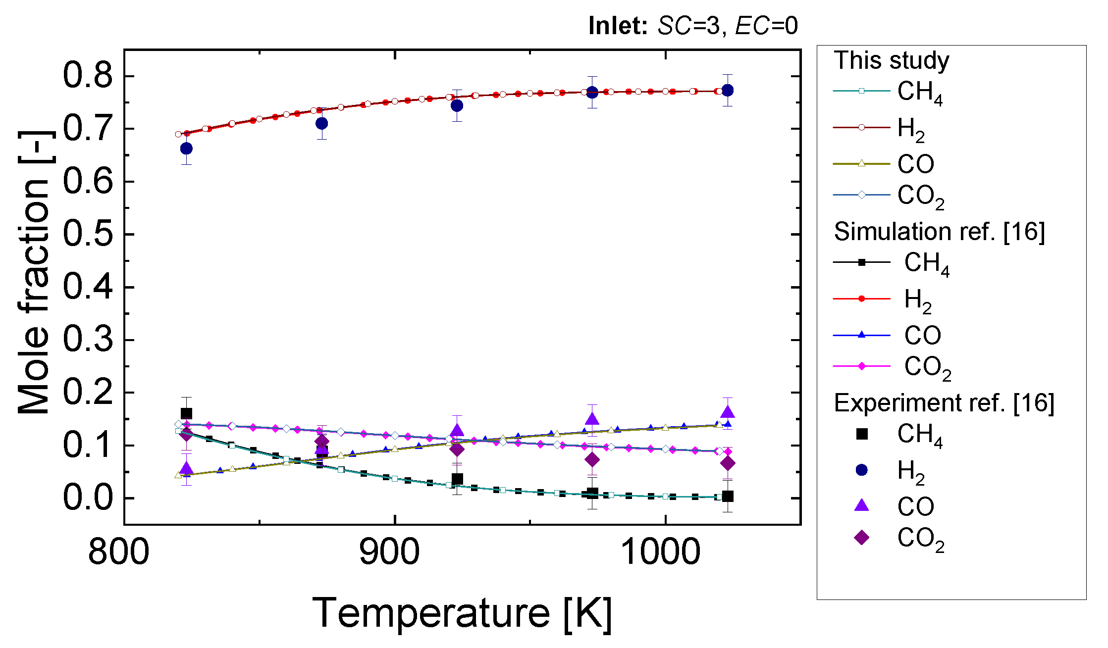
Figure 2 presents experimental data taken from the open literature [16] juxtaposed with the equilibrium calculation. As can be seen in Figure 2 Parametric Equation Formalism can successfully predict equilibrium composition of methane/steam reforming process for a wide range of temperatures. The Parametric Equation Formalism presents also good agreement with other methods of equilibrium calculation found in open literature [16].
6. Results and Discussion
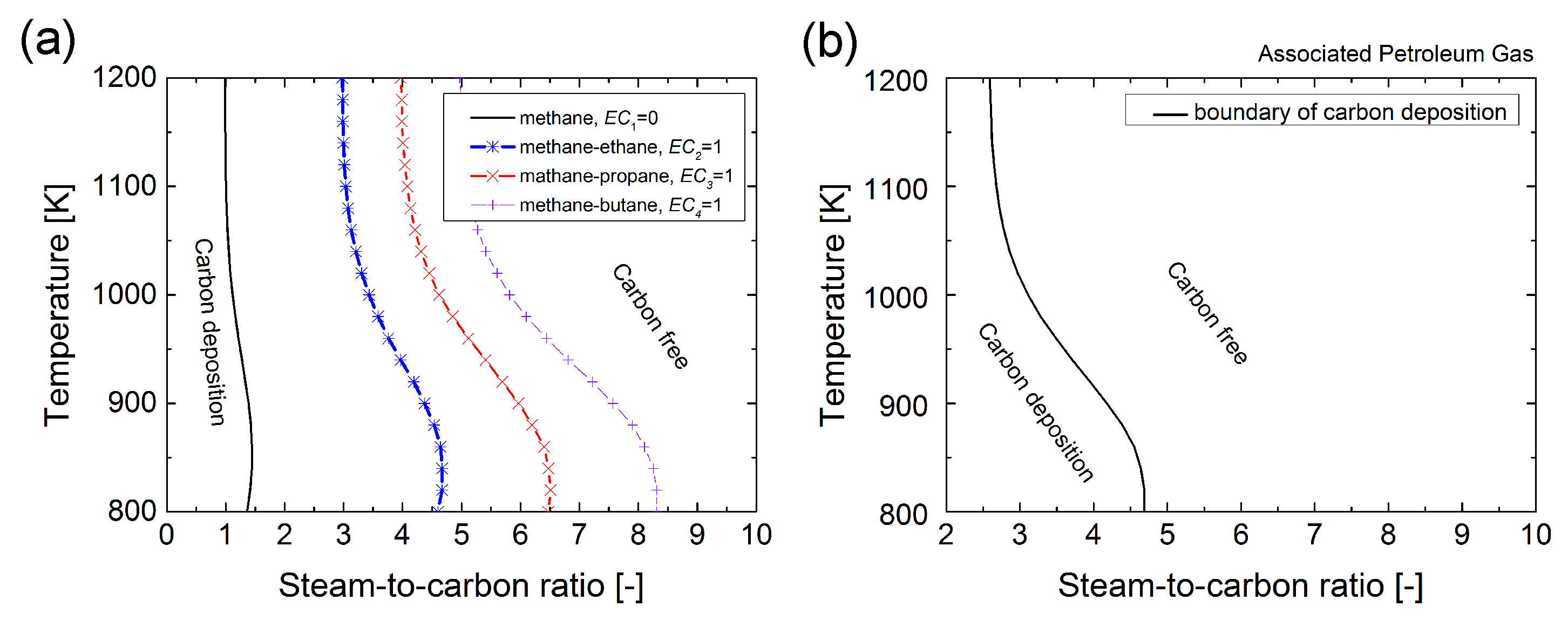
Figure 3 presents the boundary of carbon deposition regime. The effect of the heavy hydrocarbon addition on the carbon deposition regime is presented in Figure 3a. Whereas Figure 3b presents the carbon deposition boundary for model associated petroleum gas (see Table 2). As can be seen in Figure 3, the addition of heavy hydrocarbons shifts the carbon deposition border to a higher amount of steam addition. Each line in Figure 3a represents different composition of fuel. All fuels are composed in such a way that the ratio between methane and the selected heavy hydrocarbon (ethane, propane, or butane) is equal to one. It can be seen that the addition of butane at low temperature might require an amount of steam seven times higher than in the case of using pure methane. The differences in steam additions can be minimized by increasing the temperature of the process above about 1050 K. This observation is common for all heavy hydrocarbons. Figure 3b represents the carbon formation regime for the fuel composition representing the typical composition of associated petroleum gas. The relations between initial mol fraction and parameters , , , are listed in Table 3.
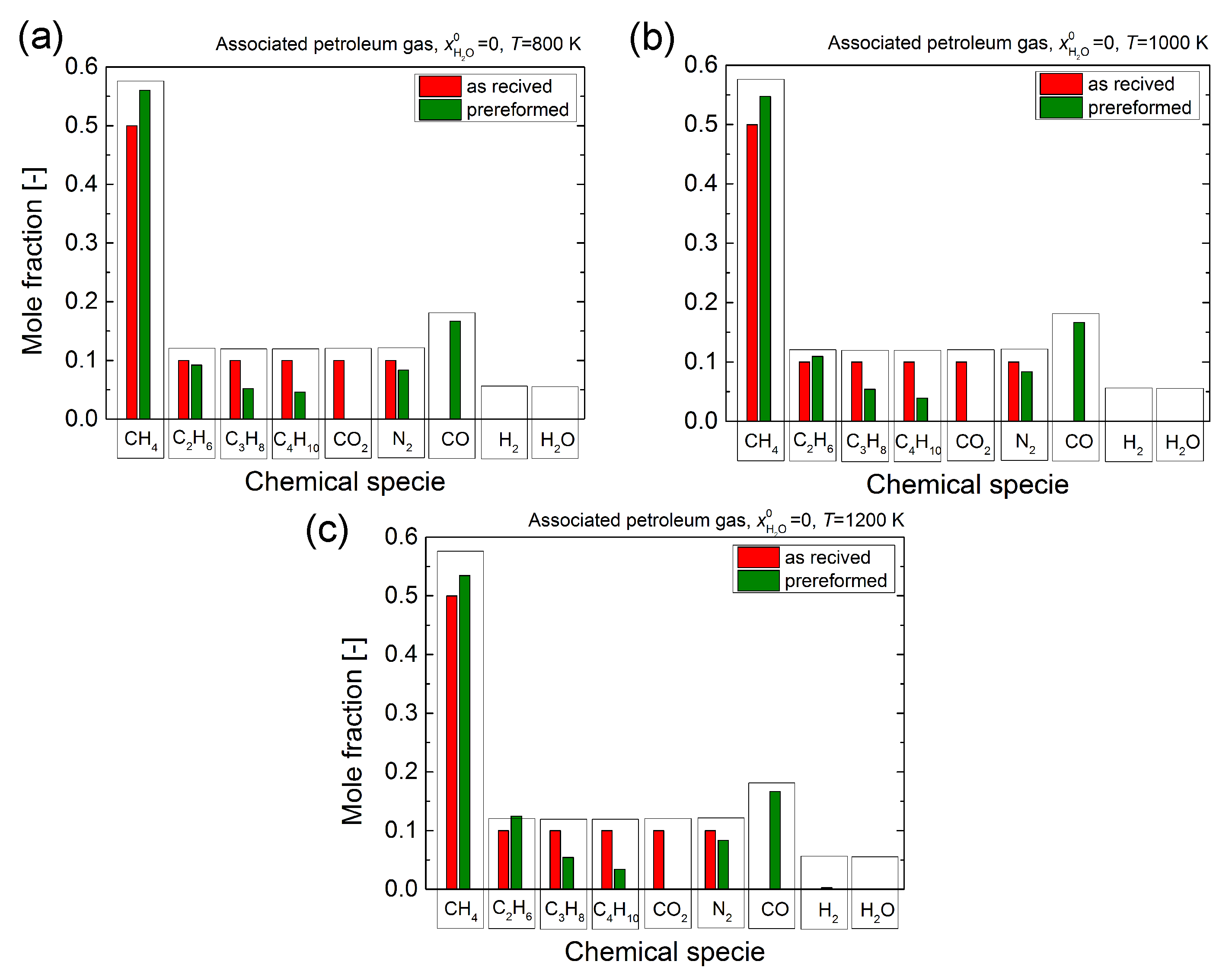
The presence of CO fraction present in the reaction products suggests the reaction’s thermodynamic course (3). Figure 4 presents pre-reforming gas composition calculated for three different temperature of the process. The equilibrium composition was juxtaposed with the initial composition (as delivered) of associated petroleum gas, as can be seen in Figure 4, the strong dry reforming reaction leads to complete conversion of initial carbon dioxide. It is also clear that dry reforming is associated with a strong reverse shift reaction. The evidence of that can be found in small content of hydrogen and a significant increase in carbon monoxide. Furthermore, the strong reverse shift reaction produces steam that trigs the methanation process of all heavy hydrocarbons. It is crucial to keep in mind that the pre-reforming process occurs with carbon deposition for all investigated temperatures.
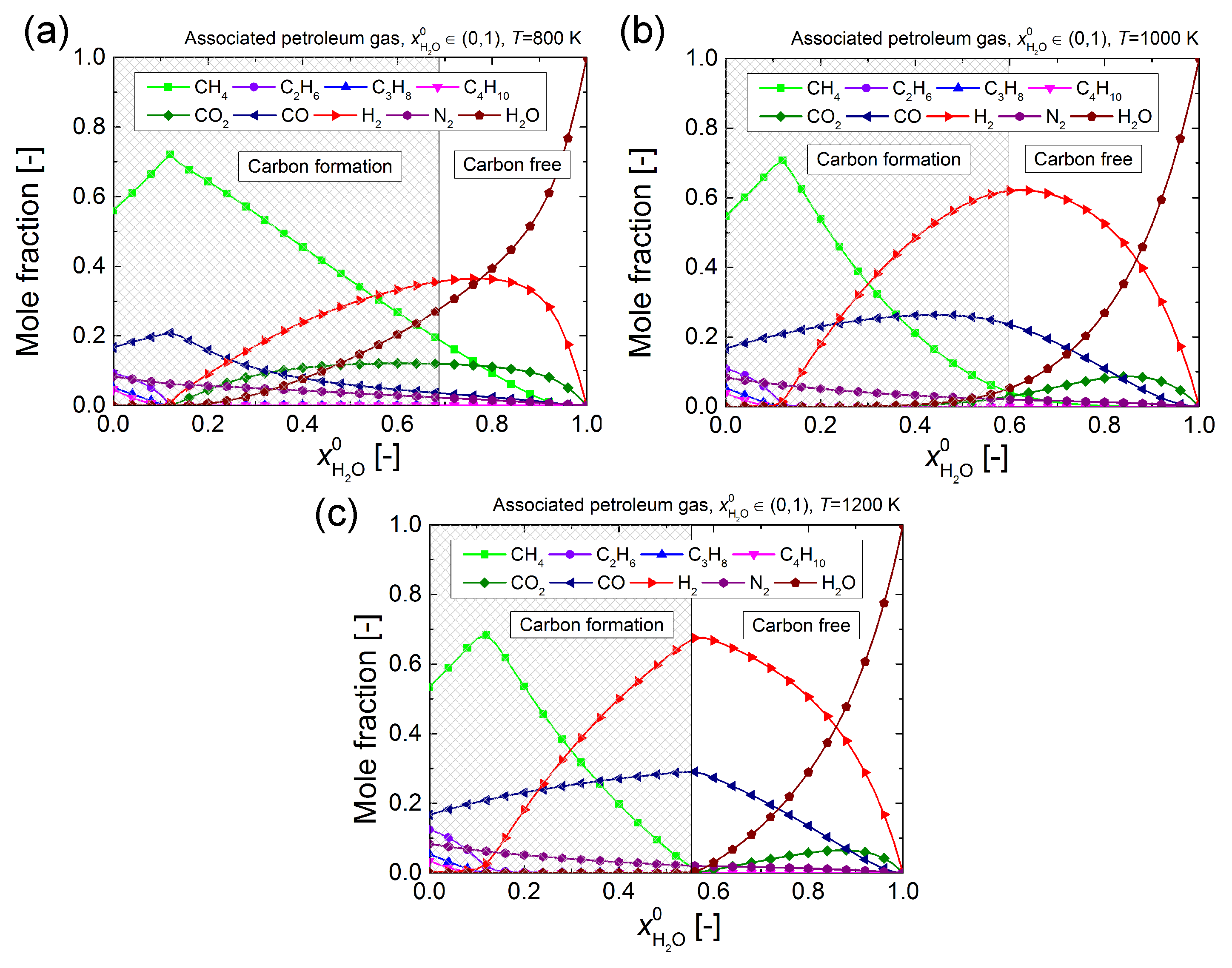
Figure 5 presents the equilibrium composition of reformed associated petroleum gas as a function of the initial steam addition. The grey area in the figure represents the carbon deposition regime. As can be seen in Figure 5 for the typical reforming temperature, all heavy hydrocarbons can be completely reformed for a very small addition of steam ( = 0.16). Moreover, the total conversion of ethane, propane, and butane occurs at exactly the same point. This is also the point where the content of steam leads to the highest concentration of methane due to the methanation process expressed by Equations (8)–(10). This is evidence that until this point methanation process was dominant over methane-steam reforming reaction (2). When steam content crosses = 0.16, there is no more heavy hydrocarbons present in the equilibrium compositions. To proceed the process outside of the carbon formation regime, decent amount of steam addition is required ( = 0.7, = 0.6 and = 0.56 for T = 800 [K], T = 1000 [K] and T = 1200 [K] respectively). The important observation is that the maximum hydrogen content is located outside of the carbon deposition regime for all investigated temperatures. In the case of high temperature, T = 1000 [K] and T = 1200 [K], the maximum hydrogen content meets together with the maximum carbon monoxide content. This is a crucial observation since both gases are a useful product that can be used in solid oxide fuel cells.
7. General Conclusions
In the presented study, the steam reforming process of associated petroleum gas was investigated. Due to the complexity of the process, a new approach was introduced to model the reaction’s equilibrium composition. The following are the main findings of the paper:
- The parametric equation formalism can be successfully used to predict the steam reforming process’s equilibrium composition.
- Carbon deposition regime strongly depends on the addition of heavy hydrocarbons. The heavier the hydrocarbon was introduced, the higher amount of steam was required to conduct the process safely. The shift is almost proportional for each tested hydrocarbon: ethane, propane, and butane.
- For all introduced hydrocarbons, a significant reduction of steam addition can be obtained by raising the process temperature up to 1050 K.
- The process temperature of 1050 K overlaps with the conditions for the optimal process product composition, which response to the higher content of carbon monoxide and hydrogen. Both are useful products of the reaction.
- Since subtracts of the considered reactions contain carbon dioxide that can be a reforming agent for a dry reforming reaction, there is a thermodynamic possibility of an undesired pre-reforming process. Pre-reforming occurs always associated with carbon deposition.
- Pre-reforming is strongly dominated by reverse shift reaction.
- Maximum production of hydrogen is observed for the initial concentration of HO between 60–70% and is always near the carbon formation regime. The peak of hydrogen concentration increase with the temperature, for 1000 K and 1200 K is about 60% and 70%, respectively.
It can be summarized that from a thermodynamic point of view, the steam reforming of associated petroleum gas can be safely conducted for 1050 K with ≈ 3. The reforming system might include a pre-reforming unit. The presented results can be used to develop and optimize the steam reforming process of associated petroleum gas for solid oxide fuel cells in hybrid energy systems.
Author Contributions
Conceptualization, R.K.; Data curation, R.K.; Formal analysis, R.K.; Funding acquisition, R.K.; Investigation, R.K. and S.G.; Methodology, R.K. and S.G.; Project administration, R.K.; Resources, R.K.; Software, S.G.; Supervision, R.K.; Validation, R.K. and S.G.; Visualization, S.G.; Writing—original draft, R.K.; Writing—review & editing, R.K. and S.G. Both authors have read and agreed to the published version of the manuscript.
Funding
This work was supported by the Polish Ministry of Science and Higher Education (grant AGH no. 16.16.210.476).
Institutional Review Board Statement
Not applicable.
Informed Consent Statement
Not applicable.
Data Availability Statement
Data available on reasonable request.
Conflicts of Interest
The authors declare no conflict of interest. The founding sponsors had no role in the design of the study; in the collection, analyses, or interpretation of data; in the writing of the manuscript, and in the decision to publish the results.
Abbreviations
The following abbreviations are used in this manuscript:
| APG: | Associated Petroleum Gas |
| SOFC: | Solid Oxide Fuel Cell |
References
- Dolinskii, S.E. Economically Attractive Technologies of Deep Conversion of Associated Petroleum Gas. Russ. J. Gen. Chem. 2011, 81, 2574–2593. [Google Scholar] [CrossRef]
- Jaszczur, M.; Hassan, Q.; Palej, P.; Abdulateef, J. Multi-Objective optimisation of a micro-grid hybrid power system for household application. Energy 2020, 202, 117738. [Google Scholar] [CrossRef]
- Damo, U.M.; Ferrari, M.L.; Turan, A.; Massardo, A.F. Solid oxide fuel cell hybrid system: A detailed review of an environmentally clean and efficient source of energy. Energy 2019, 168, 235–246. [Google Scholar] [CrossRef] [Green Version]
- Tan, W.C.; Iwai, H.; Kishimoto, M.; Brus, G.; Szmyd, J.S.; Yoshida, H. Numerical analysis on effect of aspect ratio of planar solid oxide fuel cell fueled with decomposed ammonia. J. Power Sources 2018, 384, 367–378. [Google Scholar] [CrossRef]
- Singhal, S.C.; Kendall, K. High-Temperature Solid Oxide Fuel Cells: Fundamentals, Design and Applications; Elsevier: Oxford, UK, 2003. [Google Scholar]
- Zyryanova, M.M.; Snytnikov, P.V.; Shigarov, A.B.; Belyaev, V.D.; Kirillov, V.A.; Sobyanin, V.A. Low temperature catalytic steam reforming of propane methane mixture into methane-rich gas: Experiment and macrokinetic modeling. Fuel 2014, 135, 76–82. [Google Scholar] [CrossRef]
- Gillan, C.; Fowles, M.; French, S.; Jackson, S.D. Ethane Steam Reforming over a Platinum/Alumina Catalyst: Effect of Sulfur Poisoning. Ind. Eng. Chem. Res. 2013, 52, 13350–13356. [Google Scholar] [CrossRef]
- Sucipta, M.; Kimijima, S.; Suzuki, K. Performance analysis of the SOFC-MGT hybrid system with gasified biomass fuel. J. Power Sources 2007, 174, 124–135. [Google Scholar] [CrossRef]
- Sucipta, M.; Kimijima, S.; Suzuki, K. Solid Oxide Fuel Cell–Micro Gas Turbine Hybrid System Using Natural Gas Mixed with Biomass Gasified Fuel. J. Electrochem. Soc. 2008, 155, B258–B263. [Google Scholar] [CrossRef]
- Ounia, F.; Ahmarb, E.E.; Khacefc, A.; Cormierd, J.M. Novel sliding discharge reactor for hydrogen production through hydrocarbons. In Proceedings of the 16th World Hydrogen Energy Conference, Lyon, France, 13–16 June 2006. [Google Scholar]
- Khacef, A.; Ouni, F.; Ahmar, E.E.; Aubry, O.; Cormier, J.M. Hydrogen production by methane, propane and ethanol via non-thermal plasma reactors. In Proceedings of the First Central European Symposium on Plasma Chemistry and Workshop on the Plasma-Assisted Combustion and Plasma-Aftertreatment of Combustion Flue Gases for Power Industry, Gdansk, Poland, 27–31 May 2006. [Google Scholar]
- Kaczmarczyk, R.; Gurgul, S. Model Approach of Carbon Deposition Phenomenon in Mixed H2O/CO2 Methane Reforming Process. Arch. Metall. Mater. 2014, 59, 1379–1383. [Google Scholar] [CrossRef] [Green Version]
- Assabumrungrat, S.; Laosiripojana, N.; Pavarajarn, V.; Sangtongkitcharoen, W.; Tangjitmatee, A.; Praserthdam, P. Thermodynamic analysis of carbon formation in a solid oxide fuel cell with a direct internal reformer fuelled by methanol. J. Power Sources 2005, 139, 55–60. [Google Scholar] [CrossRef]
- Assabumrungrat, S.; Laosiripojana, N.; Piroonlerkgul, P. Determination of the boundary of carbon formation for dry reforming of methane in a solid oxide fuel cell. J. Power Sources 2006, 159, 1274–1282. [Google Scholar] [CrossRef]
- Kaczmarczyk, R.; Gurgul, S. Model Approach of Carbon Deposition Phenomenon in Steam and Dry Methane Reforming Process. Arch. Metall. Mater. 2014, 59, 145–148. [Google Scholar] [CrossRef] [Green Version]
- Brus, G.; Nowak, R.; Szmyd, J.S.; Komatsu, Y.; Kimijima, S. An experimental and theoretical approach for the carbon deposition problem during steam reforming of model biogas. J. Theor. Appl. Mech. 2015, 53, 273–284. [Google Scholar] [CrossRef]
- Tuan, L.A.; Ishihara, K.N. Low-Temperature Catalytic Performance of Ni-Cu/Al2O3 Catalysts for Gasoline Reforming to Produce Hydrogen Applied in Spark Ignition Engines. Catalysts 2016, 6, 45. [Google Scholar] [CrossRef] [Green Version]
- Ptak, W.; Sukiennik, M. Changes in the Composition of te Gaseous Phase of a System Resulting from the Process of a Chemical Reaction. Bulletin de lAcademie Polonaise des Sciences. Ser. Sci. Tech. 1969, 17, 21–25. [Google Scholar]
- Ptak, W.; Sukiennik, M. The kinetics characteristic of complex systems. Arch. Metall. 1973, 18, 275–289. [Google Scholar]
- Ptak, W.; Sukiennik, M.; Olesinski, R.; Kaczmarczyk, R. Deformation of a properties resulting from a chemical reaction stoichiometry. Arch. Metall. 1987, 32, 355–362. [Google Scholar]
- Brus, G.; Kaczmarczyk, R.; Tomiczek, M.; Mozdzierz, M. Comparative study of two theoretical models of methane and ethane steam reforming process. J. Phys. Conf. Ser. 2016, 745, 032151. [Google Scholar] [CrossRef] [Green Version]
- Tomiczek, M.; Kaczmarczyk, R.; Mozdzierz, M.; Brus, G. A numerical analysis of heat and mass transfer during the steam reforming process of ethane. Heat Mass Transf. 2018, 54, 2305–2314. [Google Scholar] [CrossRef]
- Kirillov, V.A.; Amosov, Y.I.; Shigarov, A.B.; Kuzin, N.A.; Kireenkov, V.V.; Parmon, V.N.; Aristovich, Y.V.; Gritsay, M.A.; Svetov, A.A. Experimental and theoretical study of associated petroleum gas processing into normalized gas by soft steam reforming. Theor. Found. Chem. Eng. 2017, 51, 12–26. [Google Scholar] [CrossRef]
- Ilyin, V.B.; Yakovenko, R.E.; Belashov, D.M.; Zemlyakov, N.D.; Savost’yanov, A.P. Thermodynamic Study of Associated Petroleum Gas Reforming to Methane. Pet. Chem. 2019, 59, 641–649. [Google Scholar] [CrossRef]
- Shigarov, A. Modeling of low temperature steam reforming of flare gas to methane-rich fuel gas on Ni catalyst in different types of reactors. Chem. Eng. J. 2020, 397, 125313. [Google Scholar] [CrossRef]
- Akhmadullina, L.F.; Enikeeva, L.V.; Gubaydullin, I.M. Numerical methods for reaction kinetics parameters: Identification of low-temperature propane conversion in the presence of methane. Procedia Eng. 2017, 201, 612–616. [Google Scholar] [CrossRef]
- Uskov, S.I.; Potemkin, D.I.; Enikeeva, L.V.; Snytnikov, P.V.; Gubaydullin, I.M.; Sobyanin, V.A. Propane pre-reforming into methane-rich gas over ni catalyst: Experiment and kinetics elucidation via genetic algorithm. Energies 2020, 13, 3393. [Google Scholar] [CrossRef]
- Kumar, S.; Tondwal, N.; Kumar, S.; Kumar, S. Thermodynamic Modeling of Propane Reforming Processes to Quantify Hydrogen and Syngas Production with and without Product Removal. Chem. Prod. Process Model. 2016, 11, 125–140. [Google Scholar] [CrossRef]
- Mokheimer, E.M.A.; Hussain, M.I.; Ahmed, S.; Habib, M.A.; Al-Qutub, A.A. On the modeling of steam methane reforming. J. Energy Resour. Technol. 2015, 137, 1–12. [Google Scholar] [CrossRef]
- Brus, G. Experimental and numerical studies on chemically reacting gas flow in the porous structure of a solid oxide fuel cells internal fuel reformer. Int. J. Hydrogen Energy 2012, 37, 17225–17234. [Google Scholar] [CrossRef]
- Sciazko, A.; Komatsu, Y.; Brus, G.; Kimijima, S. A novel approach to improve the mathematical modelling of the internal reforming process for solid oxide fuel cells using the orthogonal least squares method. Int. J. Hydrogen Energy 2014, 39, 16372–16389. [Google Scholar] [CrossRef]
- Sciazko, A.; Komatsu, Y.; Brus, G.; Kimijima, S.; Szmyd, J.S. A novel approach to the experimental study on methane/steam reforming kinetics using the Orthogonal Least Squares method. J. Power Sources 2014, 262, 245–254. [Google Scholar] [CrossRef]
- Pajak, M.; Mozdzierz, M.; Chalusiak, M.; Kimijima, S.; Szmyd, J.S.; Brus, G. A numerical analysis of heat and mass transfer processes in a macro-patterned methane/steam reforming reactor. Int. J. Hydrogen Energy 2018, 43, 20474–20487. [Google Scholar] [CrossRef]
- Chalusiak, M.; Wrobel, M.; Mozdzierz, M.; Berent, K.; Szmyd, J.S.; Brus, G. A numerical analysis of unsteady transport phenomena in a Direct Internal Reforming Solid Oxide Fuel Cell. Int. J. Heat Mass Transf. 2019, 131, 1032–1051. [Google Scholar] [CrossRef]
- Delgado, K.H.; Maier, L.; Tischer, S.; Zellner, A.; Stotz, H. Surface Reaction Kinetics of Steam-and CO2-Reforming as Well as Oxidation of Methane over Nickel-Based Catalysts. Catalysts 2015, 5, 871–904. [Google Scholar] [CrossRef] [Green Version]
- York, A.P.E.; Xiao, T.C.; Green, M.L.H.; Claridge, J.B. Methane Oxyforming for Synthesis Gas Production. Catal. Rev. 2007, 49, 511–560. [Google Scholar] [CrossRef]
Figure 1.
Computation flow of Parametric Equation Formalism.

Figure 2.
Equilibrium calculation using Parametric Equation Formalism versus experimental data from the ref. [16].
Figure 2.
Equilibrium calculation using Parametric Equation Formalism versus experimental data from the ref. [16].

Figure 3.
Boundaries of carbon deposition (a) carbon deposition regime for different carbohydrates fuels (b) carbon formation regime for model associated petroleum gas.
Figure 3.
Boundaries of carbon deposition (a) carbon deposition regime for different carbohydrates fuels (b) carbon formation regime for model associated petroleum gas.

Figure 4.
Thermodynamic possibility of pre-reforming of associated petroleum gas (a) T = 800 K, (b) T = 1000 K and (c) T = 1200 K.
Figure 4.
Thermodynamic possibility of pre-reforming of associated petroleum gas (a) T = 800 K, (b) T = 1000 K and (c) T = 1200 K.

Figure 5.
Equilibrium composition of reformed associated petroleum gas as a function of steam content (a) at 800 [K], (b) at 1000 [K] and (c) 1200 [K].
Figure 5.
Equilibrium composition of reformed associated petroleum gas as a function of steam content (a) at 800 [K], (b) at 1000 [K] and (c) 1200 [K].


Table 1.
Change of mole fraction in the reformer.
| Symbol | Steam | Shift | Dry | Ethane | Propane | Butane |
|---|---|---|---|---|---|---|
Table 2.
Assumed composition of model associated petroleum gas.
| Chemical Species | ||||||
|---|---|---|---|---|---|---|
| Mole fraction | 50 | 10 | 10 | 10 | 10 | 10 |
Table 3.
Boundary conditions: relation between initial mol fraction and parameters , , , .
Publisher’s Note: MDPI stays neutral with regard to jurisdictional claims in published maps and institutional affiliations. |
© 2021 by the authors. Licensee MDPI, Basel, Switzerland. This article is an open access article distributed under the terms and conditions of the Creative Commons Attribution (CC BY) license (http://creativecommons.org/licenses/by/4.0/).
Share and Cite
MDPI and ACS Style
Kaczmarczyk, R.; Gurgul, S. A Thermodynamic Analysis of Heavy Hydrocarbons Reforming for Solid Oxide Fuel Cell Application as a Part of Hybrid Energy Systems. Energies 2021, 14, 337. https://0-doi-org.brum.beds.ac.uk/10.3390/en14020337
AMA Style
Kaczmarczyk R, Gurgul S. A Thermodynamic Analysis of Heavy Hydrocarbons Reforming for Solid Oxide Fuel Cell Application as a Part of Hybrid Energy Systems. Energies. 2021; 14(2):337. https://0-doi-org.brum.beds.ac.uk/10.3390/en14020337
Chicago/Turabian StyleKaczmarczyk, Robert, and Sebastian Gurgul. 2021. "A Thermodynamic Analysis of Heavy Hydrocarbons Reforming for Solid Oxide Fuel Cell Application as a Part of Hybrid Energy Systems" Energies 14, no. 2: 337. https://0-doi-org.brum.beds.ac.uk/10.3390/en14020337
Note that from the first issue of 2016, this journal uses article numbers instead of page numbers. See further details here.