
Adaptive Fuzzy PID Based on Granular Function for Proton Exchange Membrane Fuel Cell Oxygen Excess Ratio Control


1
School of Automation, Central South University, Changsha 410083, China
2
Hunan Xiangjiang Artificial Intelligence College, Changsha 410083, China
3
Department of Civil, Environment & Geomatic Engineering, University College London, London WC1E 6BT, UK
*
Author to whom correspondence should be addressed.
Energies 2021, 14(4), 1140; https://0-doi-org.brum.beds.ac.uk/10.3390/en14041140
Submission received: 10 January 2021
/
Revised: 16 February 2021
/
Accepted: 17 February 2021
/
Published: 21 February 2021
(This article belongs to the Special Issue Hydrogen and Fuel Cell Technology, Modelling and Simulation)
Abstract
:An effective oxygen excess ratio control strategy for a proton exchange membrane fuel cell (PEMFC) can avoid oxygen starvation and optimize system performance. In this paper, a fuzzy PID control strategy based on granular function (GFPID) was proposed. Meanwhile, a proton exchange membrane fuel cell dynamic model was established on the MATLAB/Simulink platform, including the stack model system and the auxiliary system. In order to avoid oxygen starvation due to the transient variation of load current and optimize the parasitic power of the auxiliary system and the stack voltage, the purpose of optimizing the overall operating condition of the system was finally achieved. Adaptive fuzzy PID (AFPID) control has the technical bottleneck limitation of fuzzy rules explosion. GFPID eliminates fuzzification and defuzzification to solve this phenomenon. The number of fuzzy rules does not affect the precision of GFPID control, which is only related to the fuzzy granular points in the fitted granular response function. The granular function replaces the conventional fuzzy controller to realize the online adjustment of PID parameters. Compared with the conventional PID and AFPID control, the feasibility and superiority of the algorithm based on particle function are verified.
1. Introduction
The energy crisis and environmental pollution have become huge challenges facing the world today, and all countries are committed to deploying new energy industries and developing low-carbon technologies [1]. The hydrogen fuel cell has become a research hotspot in recent years because of its high fuel calorific value, clean and pollution-free properties. As one of the varieties of fuel cells, a proton exchange membrane fuel cell (PEMFC) converts hydrogen energy into electric energy. The PEM fuel cell has the advantages of low noise, no pollution, quick start, low operating temperature, environmentally-friendliness, and compact structure [2,3]. It has a good application prospect in solving the environmental and energy problems that hinder automobile development and has started the development of vehicle commercialization [4,5]. However, in practical applications, a transient current is required for the external load of the fuel cell to satisfy the stable operation of the system. Oxygen starvation may occur if the anode side oxygen supply is insufficient, which can cause rupture of membranes and permanent damage to the stack in severe conditions. In order to alleviate membrane degradation and extend the lifetime of fuel cells, this problem can be effectively solved by adjusting the oxygen excess ratio which is a key parameter for the performance improvement of a proton exchange membrane fuel cell. In addition, the main source of parasitic power is the air compressor of the auxiliary system, so the adjustment of the oxygen ratio can effectively optimize the efficiency of the fuel cell. A control-oriented dynamic fuel cell model is the prerequisite for selecting a better control strategy. Therefore, for the study of oxygen excess ratio, a dynamic control fuel cell model must be established as the premise of choosing a better control strategy, and the key parameters of the fuel cell, such as stack voltage, net power and compressor power, will also be used as important indexes to evaluate the control effect [6,7,8]. A dramatic and instantaneous decline in the oxygen excess ratio results in oxygen starvation, which damages the components of the system and greatly affects the performance of the fuel cell system.
In order to solve the problem of oxygen excess ratio in the dynamic operation of a fuel cell stack system, experts have conducted a lot of research on fuel cell modeling and oxygen excess ratio control. Abdin Z et al. went beyond the empirically described characteristics of fuel cells and established a dynamic model based on parameters of direct physical significance, exploring the effects of pressure, temperature, humidification and partial pressure of reactants on the performance of the stack [9]. Bao C et al. established a control-oriented model to realize the modeling and control of air flow and hydrogen flow recycling of a PEMFC system [10]. Sun L et al. implemented PEMFC oxygen excess ratio control using data drive [11]. For the oxygen excess ratio of PEMFC, Chen J et al. referred to an optimized control method [12]. Nowadays, many control strategies have been proposed for regulating the oxygen excess ratio [2]. Adaptive control methods include model reference control (MRC) [13] and adaptive robust control (RAC) [14]. Model predictive control (MPC) [15,16], sliding mode control (SMC) [17], and observer-based non-linear control methods [18] have also been reported for adjusting the oxygen excess ratio to avoid oxygen starvation and optimize fuel cell stack performance. In order to realize the control of oxygen excess ratio conveniently and efficiently, a control strategy combining PID and fuzzy control based on granular function was proposed. Fuzzy theory can transform expert experience into language that can be recognized by a machine, which makes the controller more intelligent and effectively improve the control precision of a non-linear and uncertain system [19,20,21]. Granular computing can effectively solve the problem of the fuzzy rules explosion in the conventional fuzzy control and ensure a better control effect by oxygen excess ratio regulation [22,23,24].
In this paper, a control-oriented PEMFC dynamic model was established to describe the stack voltage, anode flow, cathode flow and membrane hydration model in the stack model. Meanwhile, the compressor, cooler and humidifier were included in the auxiliary systems. The conventional PID control is a linear control strategy, which is not appropriate for complex nonlinear objects. Adaptive fuzzy PID (AFPID) control also had been investigated, but due to limited fuzzy rules, the control precision of oxygen excess ratio cannot be completely satisfactory. Therefore, in order to avoid the fuzzy rules explosion, GFPID was proposed to eliminate the fuzzification and defuzzification. The granulator replaces the conventional fuzzy controller to realize the offline tuning of PID parameters. By analyzing the simulation results of three control strategies, the feasibility and superiority of the algorithm based on granular function were verified.
2. System Description and Modeling
A proton exchange membrane fuel cell is a non-linear, time-variant, multi-coupled system with complex and variable internal operating conditions. Therefore, the establishment of accurate and reliable proton exchange membrane fuel cell model is the prerequisite for the research of oxygen excess ratio control strategy [25].
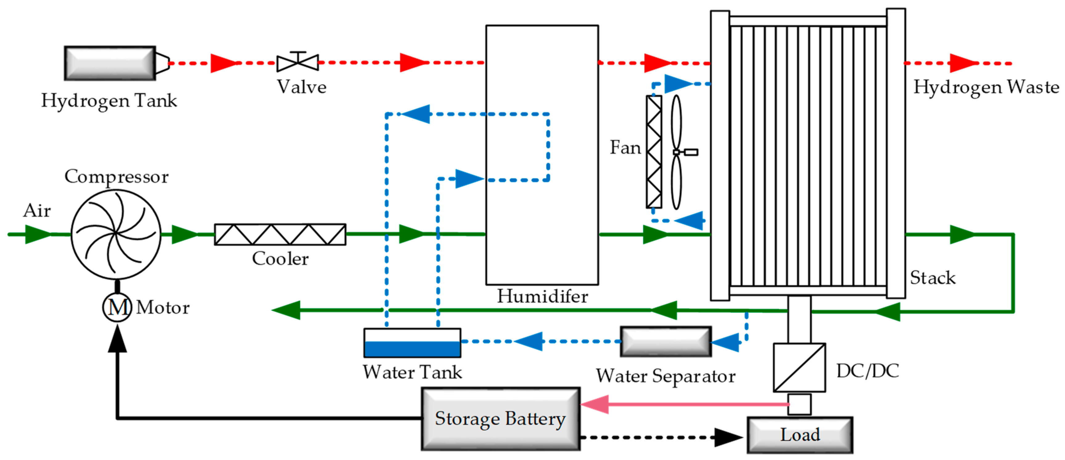
The proposed PEMFC system model in this paper is relatively complete, including the PEMEFC stack model system and auxiliary system. The stack model is composed of four sub-models: stack voltage, anode flow, cathode flow and membrane hydration. The auxiliary system model is constructed by three sub-models: a dynamic model of air compressor, and static models of the cooler and humidifier. A control-oriented dynamic model for fuel cell was used to investigate a better control strategy to obtain a better operation condition of the PEMFC system which can be adjusted by the oxygen excess ratio.
Considering the complex mass transfer, thermodynamics, and electrochemical reactions of fuel cells in operation, some reasonable assumptions were made to discuss this part of the phenomenon from the perspective of micro argument, which often ignores the application of actual physical systems to engineering. Three assumptions are made for the mathematical model of the fuel cell system:
- Gas follows the ideal gas law at high temperature and low pressure. In order to simplify the dynamic behavior of gas, it is assumed that the behavior of gas in the system also follows the ideal gas law, that is, there is no interaction between molecules.
- The ideal cooler can keep the fuel cell system temperature at a constant temperature of 80 °C, and the gas passing through the cooler only involves the change of thermodynamic properties.
- The humidifier can effectively control the fuel humidity entering the system at the preset relative humidity, so as to improve the proton transport efficiency and prevent the dryness of the polymer membrane.
2.1. Description of Proton Exchange Membrane Fuel Cell (PEMFC) Stack System
In practical operation, overpotential caused by the polarization phenomenon should be taken into consideration in the degradation of actual output voltage of PEMFC. The stack overpotential of irreversible loss mainly includes activation overpotential, ohm overpotential and concentration overpotential. According to the established PEMFC output characteristic empirical formula, the output voltage of a single cell can be expressed as follows:
where is the thermodynamic electromotive force which can be obtained according to the redox reaction in the PEM fuel cells. Based on the empirical model, the specific expression is as follows [9,25]:
In Equation (1) is the activation overpotential generated by the activation loss. is the ohm overpotential generated by the ohm loss, ohmic, and is the ohm overpotential generated by the ohm loss. is expressed as [26]:
where is the numerical value of stack current density, and are activation overpotential, which are the pressure of the oxygen in the reaction environment and stack temperature related parameters when current density is zero, respectively.
refers to the voltage drop generated by the equivalent internal resistance of the battery during the electricity generation process. The ohmic overpotential has a linear relationship with stack current.
where is the ohmic resistance which is related to membrane conductivity () and membrane thickness (). The calculation formula is as follows:
is a kind of voltage loss caused by the recession of concentration of the reactant in the electrochemical reaction process. The specific equation is described as follows [27,28]:
where parametric coefficient is related to the PEM fuel cell system and its operation condition, and represents the actual current density of the cell. is the maximum current density of the cell. Therefore, PEMFC stack consists of identical single cells in series, and the stack voltage () can be expressed as:
where is the number of the fuel cell.
The cathode side is the place where the fuel cell reduction reaction takes place. The water generated during the reduction reaction may lead to the flooding phenomenon, which will cause the blockage of the hole and increase the mass transfer resistance. Therefore, the performance of the cathode side becomes an important role affecting the fuel cell system. The cathode side feed gas contains oxygen, nitrogen and water vapor. The mass transfer of oxygen involves reduction reactions. The water balance at the cathode side involves the mass transfer of water and the water produced by the reduction reaction . The water molecule migration caused by a combination of the electroosmosis effect and weaker concentration gradient on both sides of the membrane. The state equilibrium equation of these three substances at the cathode side are expressed as follows:
The compressor pumps air into the fuel cell system. Stack current is linearly related to the compressor voltage, so the stack current can affect the amount of oxygen consumption and water generation of the fuel cell. Therefore, the oxygen flow consumed by the electrochemical reaction and the water flow generated are expressed as:
The anode feed flows out of the high-pressure hydrogen tank and is humidified by a humidifier after passing through the pressure relief valve and then supplied to the anode. The anode side feed gas may be considered to contain hydrogen and water vapor. Hydrogen at the anode is also involved in electrochemical reactions and also has the effect of water molecule migration.
The specific expression of the phenomenon of water molecule migration caused by electroosmosis and water molecule concentration gradient effect is as follows:
2.2. Description of PEMFC Auxiliary Component System
Proton exchange membrane fuel cell is one of the polymer membrane fuel cells, whose cathode side feed must theoretically be oxygen. However, based on the economical consideration of operation costs, most PEM fuel cells use air as the feed at the cathode side of the stack system. Therefore, this paper has also taken air as the feed and used oxygen in the air as the fuel supply. To ensure adequate oxygen is supplied to the system the air compressor was used to compulsively pump sufficient air into the system.
The dynamic situation of the compressor is related to the performance of the stack, which directly affects the output voltage of the system. Therefore, the dynamic model of an air compressor is established, and the equations are as follows:
According to the law of conservation of energy, compressing the air through the air compressor is equivalent to the compressor doing physical work on this part of the air, which is converted into internal energy of the air. Therefore, the air temperature will rise, even exceeding the appropriate operating temperature of the stack. Excess air temperature will further affect the smooth operation of PEMFC. Therefore, the system used the cooler to ensure the air feeding temperature to maintain a reasonable value so that it reaches the optimal operating temperature. This paper assumed that the pressure drop is not obvious after the cooler is applied (). After being cooled by the cooler, the air humidity is expressed as follows:
After being cooled by the cooler, air needs to be humidified through a humidifier before being pumped into the stack. In addition, the membrane of the fuel cell needs to be maintained in a highly humidity state, the protons produced by the hydrogen oxidation reaction can be transferred from the anode side to the cathode side. The reduction reaction of the stack takes place at the cathode side, generating water and electric energy. The desiccation or insufficient water content of the membrane will result in the decrease of proton transport efficiency and thus influence the overall operation performance of the stack. In a severe situation, the membrane will rupture and the stack break down.
This paper assumes that the internal temperature of the humidifier is the same as the outlet temperature of the cooler . Therefore, the humidifier makes the feed gas reach a predetermined relative humidity. The pressure relative humidity and flow rate are determined at the humidifier outlet as:
As mentioned above, the distribution diagram of PEMFC system architecture is shown in Figure 1. In addition, considering that there are many abbreviations of parameters and symbols involved in Equations (8)–(23), they are listed in the Nomenclature at the end of the paper for unified explanation. Some key system parameter values used in the modeling process are shown in Appendix A.
3. Control Strategy
There are two main gas supply control strategies for PEMFC in the existing research. The flow of hydrogen into the anode is controlled by adjusting the opening and closing degree of the solenoid valve and the flow of air into the cathode by adjusting the voltage and speed of the air compressor. The research method of this paper is to control the air flow into the cathode side of the stack by controlling the working voltage of the air compressor. The oxygen supply state of PEMFC system is measured by the oxygen excess ratio (OER). The oxygen excess ratio reflects the excess degree of oxygen flow provided by the air compressor, which is expressed as:
where is the oxygen excess ratio, inlet flow rate of oxygen, is reaction consumed rate of oxygen.
In the actual operation of PEMFC systems, the load occasionally needs a transient current to satisfy the stable operation of the system, while the air compressor usually fails to provide sufficient air supply to respond to this transient demand. If this phenomenon is serious, the value of oxygen excess ratio is less than 1 where , and it is called oxygen starvation. When the PEMEC system remain in this state for a long time it can cause permanent damage to the membrane, which causes serious damage to the fuel cell performance. A high-speed air compressor can effectively alleviate this phenomenon, but it will create the problem that the parasitic power loss of an auxiliary system increases and negatively influences the net power.
The optimal oxygen excess ratio operating point will determine the performance of the system, and the optimal oxygen excess ratio operating point of the system can be obtained by a step test. According to the step test, the system established in this paper can obtain a higher net power when the operating point of the peroxide ratio is set to 2. Therefore, was selected as the optimal oxygen excess ratio of the system.
An effective control method was adopted to avoid an oxygen starvation phenomenon and adjust the oxygen excess ratio in time. In this paper, three oxygen excess ratio control strategies were investigated respectively to obtain better control performance and effectively reduce the extra power loss caused by parasitic power.
3.1. Conventional PID Method
The PID controller has a simple structure and is widely applied in industrial production. It is applicable to a linear time-invariant system. The proportion, integral and differential of error is composed of a linear combination to control the controlled object, which is called PID controller. The formula of a PID controller is given as follows:
where is the system error, is the proportionality coefficient, is the integration time constant, is the differential time constant. is integral coefficient, is differential coefficient.
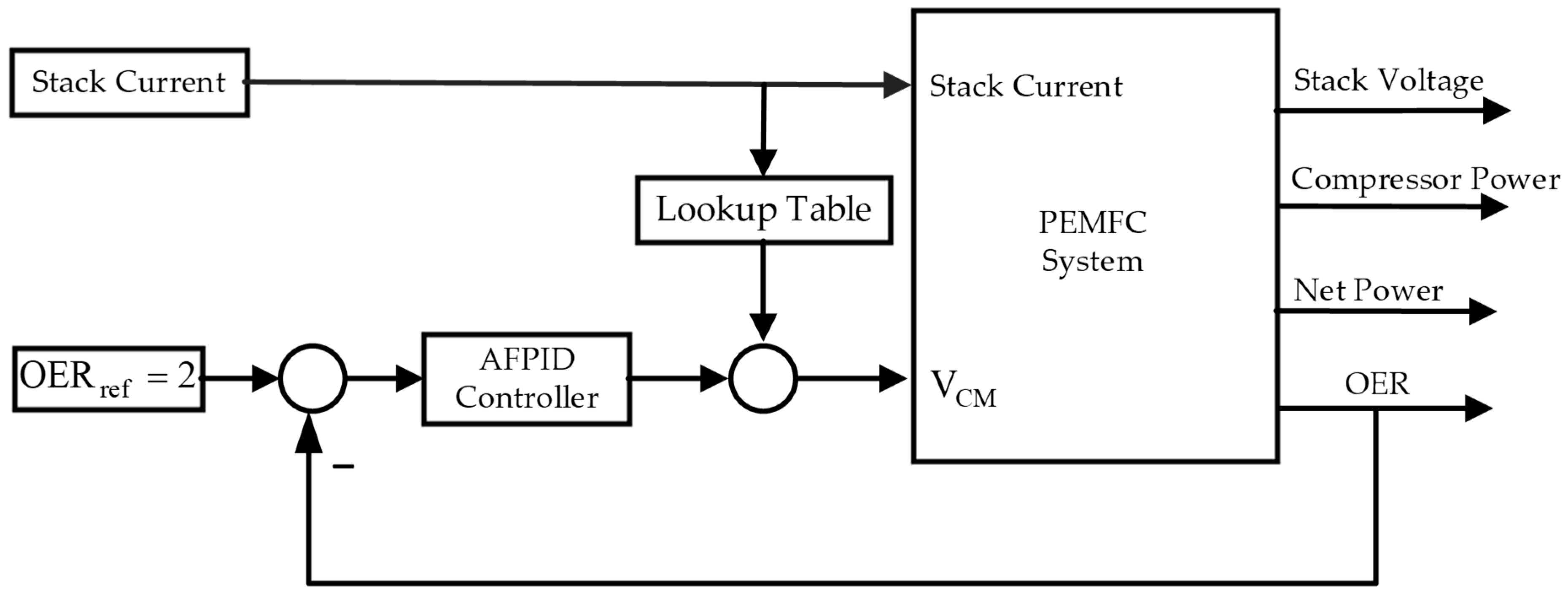
The air compressor is regulated through feedforward control related to load current size and feedback control related to the OER. In high-precision servo control systems, feedforward control can improve the tracking performance of the system. Feedforward control was to control the air compressor voltage according to the load current and feedback control was to the error value of the actual oxygen excess ratio and reference oxygen excess ratio. The PID was selected by the Ziegler–Nichols empirical equation to meet control result of the oxygen excess ratio is more accurate. The tuning criterion of the Ziegler–Nichols method is to make the PID loop have the best effect on noise suppression. The parameters adjusted by this method will have large gain and large overshoot. The Ziegler–Nichols method for control parameter setting is shown in Table 1, where, is the limit gain, is the oscillation period. Finally, the result of the PID parameter setting can show that is 32, is 15 and is 0.5.
3.2. Adaptive Fuzzy PID
Non-linear systems exist widely in practical industrial control systems and have complex characteristics such as strong coupling, great inertia and large time delay. As a non-linear system, the internal parameters of proton exchange membrane fuel cell (PEMFC) system change with the operation condition. When the internal parameters fluctuate sharply, the PID control for the oxygen excess ratio (OER) has some problems, such as slow reaction time, large fluctuation of air compressor pressure and net output power. PID control is difficult to solve.
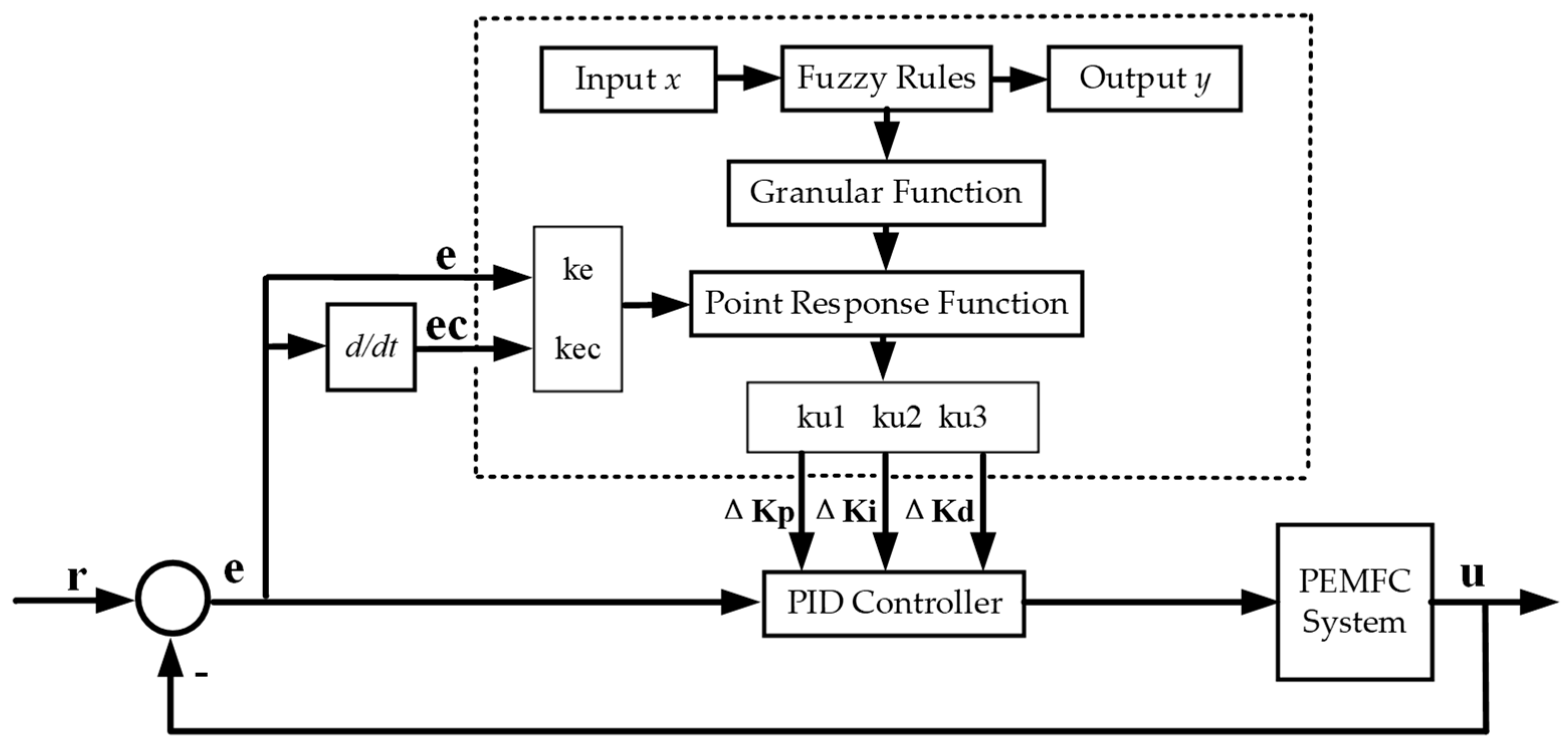
Fuzzy control has the advantages of not relying on the accurate mathematical model of the controlled object, easy to be understood, strong robustness, and strong adaptability. Fuzzy control is based upon the control decision table to decide the size of the control amount. It can effectively control proton exchange membrane fuel cells. The adaptive fuzzy PID control strategy was adopted in this paper. Combining the conventional PID controller with fuzzy controller realizes fuzzy self-tuning of PID parameters through adjustment of the variables and . and are gain adjustments for , and , respectively. The adaptive Fuzzy PID control framework of PEMFC is shown in Figure 2.
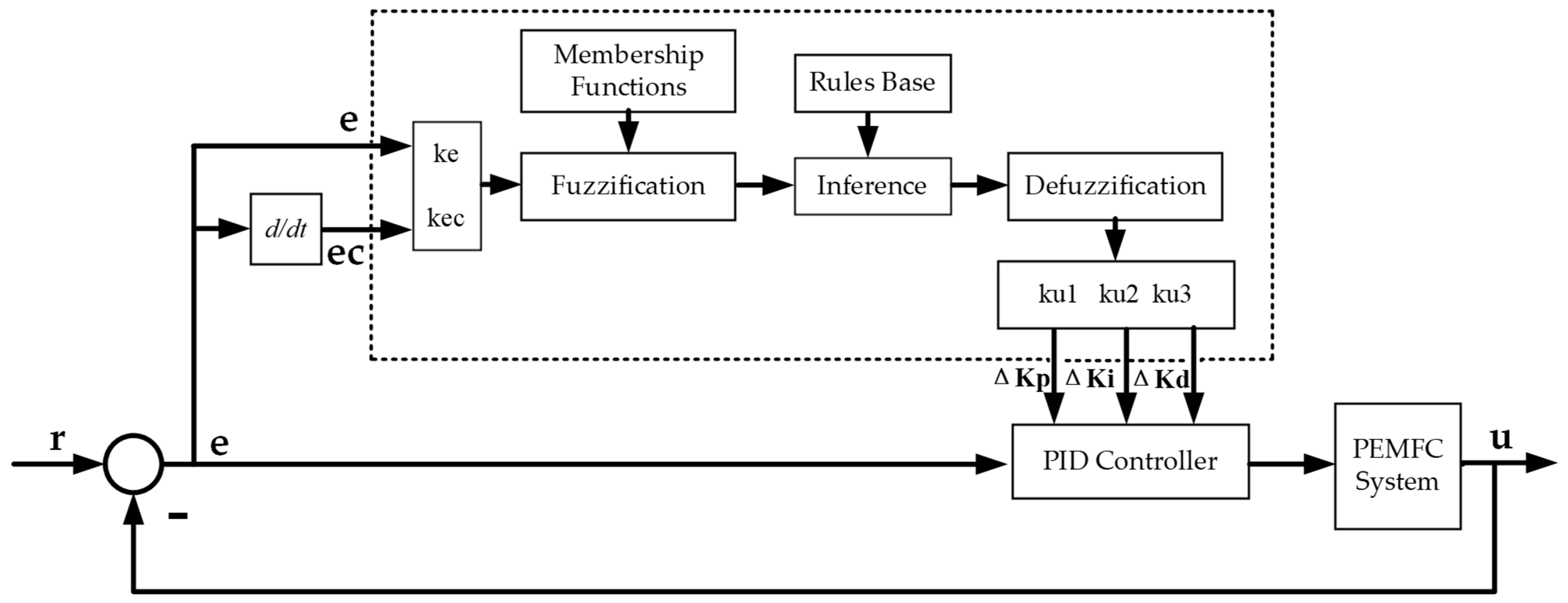
The adaptive fuzzy PID controller architecture is shown in Figure 3. The controller has two input variables and three output variables and . In two input variables, is the error between the actual oxygen excess ratio and the reference oxygen excess ratio and is the change of error. The output variables and express real-time adjustment of the gain, respectively. Three gain variations were adjusted online by using three fuzzy controllers and , respectively. is the oxygen excess ratio of PEM fuel cell.
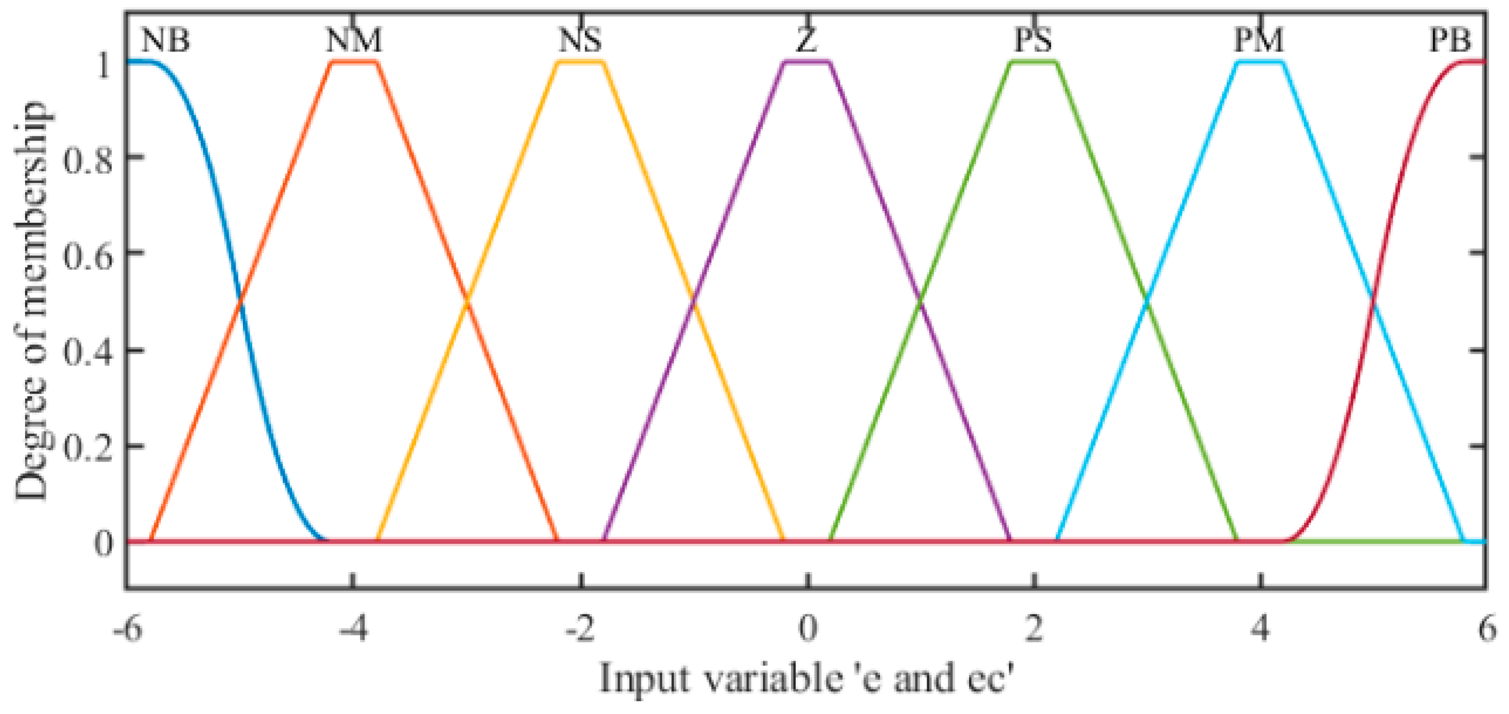
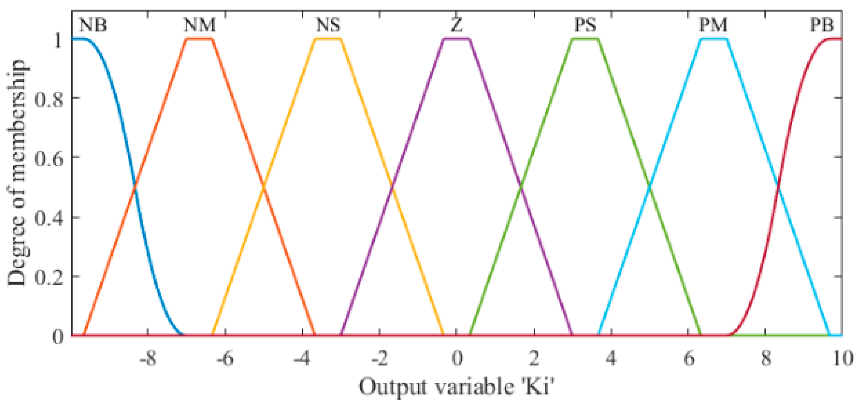
Fuzzification is to assign the input variables of a system to an appropriate fuzzy set according to their corresponding membership functions. Two input variables of the fuzzy controller ( and ) are the initial inputs, which are crisp set. The quantization factor ( and ) is a quantization factor, which can convert the initial input to the fuzzy domain ( and ). and are converted into fuzzy domain and respectively. The fuzzy domain for is [−5, 5], is [−5, 5]. In Table 2, since the change of proportional gain has the greatest influence on the system, when the input deviation is PZ (Positive Zero) and NZ (Negative Zero), the influence on the output is different, so the linguistic value of the controller is set as 8. fuzzy variable is different from . This paper took as an example, the two input and output fuzzy variables based on linguistic are expressed as NB (Negative Big), NM (Negative Medium), NS (Negative Small), Z (Zero), PS (Positive Small), PM (Positive Middle) and PB (Positive Big).
The membership functions employed in this paper include trimf type (triangle-shape grade of membership function), trapmf type (trapezoid shaped membership function) and smf type (sigmoid membership function). The membership function curves for and are shown in Figure 4 and Figure 5. The membership degree is calculated by the membership function curve. Fuzzy rules for the form of ‘‘If... Then” stated had a total of rule base, which was available for each output. For example: part of the rules in Table 3 is as follows:
The fuzzy rule base is the core part of the fuzzy system. General fuzzy rules can be obtained in the following two ways: empirical generalizations or adopting the learning algorithm based on the measured data. The fuzzy rule is obtained based on the behavior and experience of PEMFC in this paper. The fuzzy logic rule bases in this paper were designed as expressed in Table 2, Table 3 and Table 4.
Based on the fuzzy rule base, the fuzzy inference machine maps the fuzzy set on the input space to the fuzzy set on the output space. The output fuzzy set are identified using the fuzzy implication method. The inference rule of min-max fuzzy implication is selected in this paper.
After the fuzzy logic inference engine, the output is a fuzzy set, and the fuzzy value is equivalent to a crisp value by means of defuzzification. Defuzzification completes the transformation of mapping a fuzzy set of output space to a definite point to achieve the aim of practical application. , and are the scale factor of three fuzzy controllers and , which can calculate the final values and through the transformation of the domain.
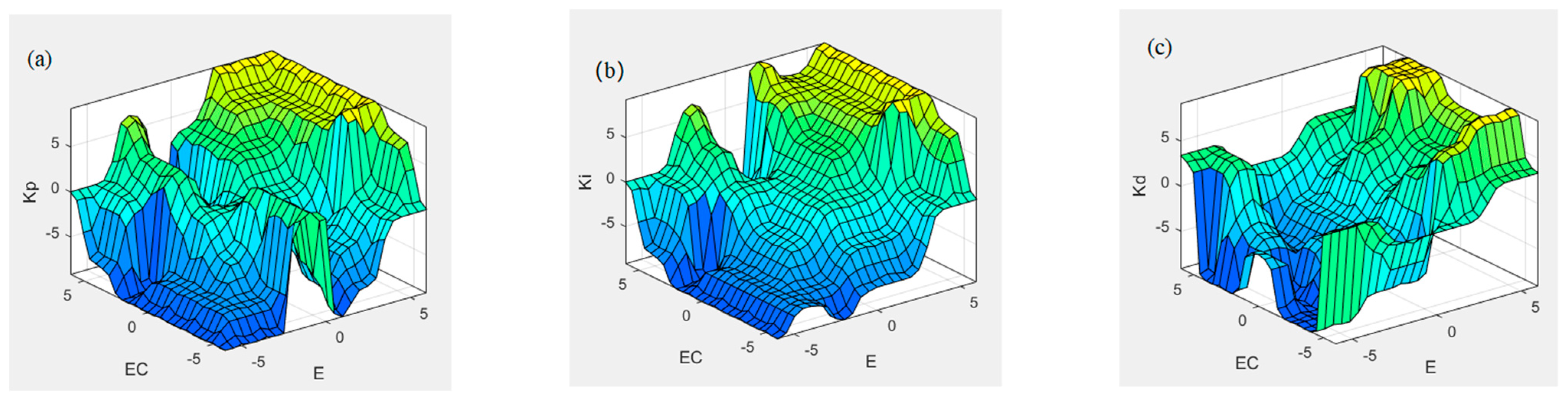
There are five common defuzzification strategies, namely centroid (centroid of area), bisector (bisector of area), mom (mean value of maximum), som (smallest value of maximum), and lom (largest value of maximum). In this paper, bisector is selected for defuzzification for its advantages of intuitive, reasonable and simple calculation. The fuzzy controller surface is shown in Figure 6.
3.3. Granular Function Fuzzy PID
In recent study, Granular computing is a research hotspot in artificial intelligence field. Granular computation is mainly used in uncertain, fuzzy, imprecise and mass information objects. The process of granulating information is more consistent with human cognition so that it is easier to be understood. In the process of realizing the accurate control of the controlled object, the conventional fuzzy control inevitably needs to formulate the corresponding fuzzy rule base, but in order to achieve higher control accuracy, the fuzzy explosion phenomenon will occur when the number of fuzzy rules is set to a certain extent. This problem has also become a technical bottleneck that makes fuzzy control difficult to solve at the present stage. Based on this phenomenon, a PEMFC oxygen excess ratio fuzzy control algorithm based on granular function is proposed. The process of fuzzification and defuzzification is eliminated. After the fuzzy information is granulated, the granular function is obtained by fitting the data to replace the fuzzy controller in AFPID, which can avoid fuzzy explosion.
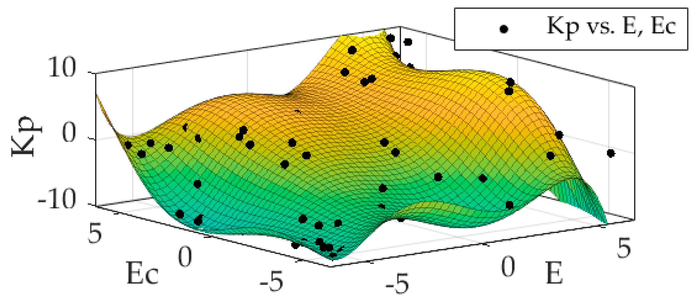
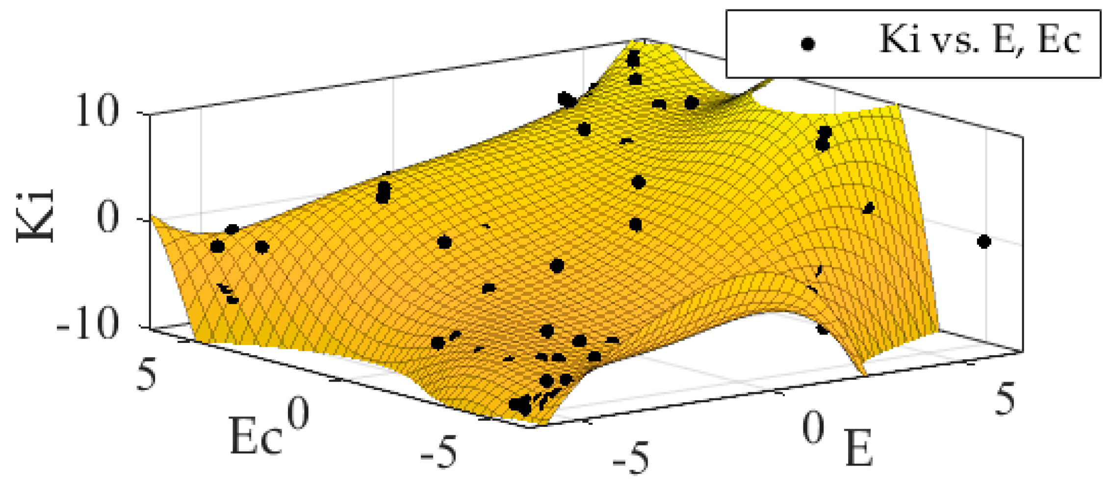
In an adaptive fuzzy control system based on granular function, the whole system is controlled by the granular response function. The granular function fuzzy PID control structure is shown in Figure 7. The number of rules would not affect the operation of the system, but are only related to the fuzzy points of the granule response function after being fitted. The design scheme is as follows. Firstly, according to the fuzzy rule base established by AFPID, the fuzzy rule granule points of and are uniformly selected to accomplish the granulation of fuzzy information. Secondly, the cftool tool of MATLAB/Simulink is used to complete the 5-order fitting of fuzzy regular grain points. Finally, as shown in Figure 8, Figure 9 and Figure 10, and obtained a fitting surface and a fitting polynomial equation which is the granular function defined beforehand, respectively.
For example: the coefficients of the fifth-order fitting granular function for are shown in Table 5.
Accordingly, the fitting polynomial equation for is as follows:
where and are independent variables of functional equation, and are dependent variables of corresponding granular functional equation. Finally, the granular functions were introduced into the system instead of the original fuzzy controller.
4. Results and Discussion
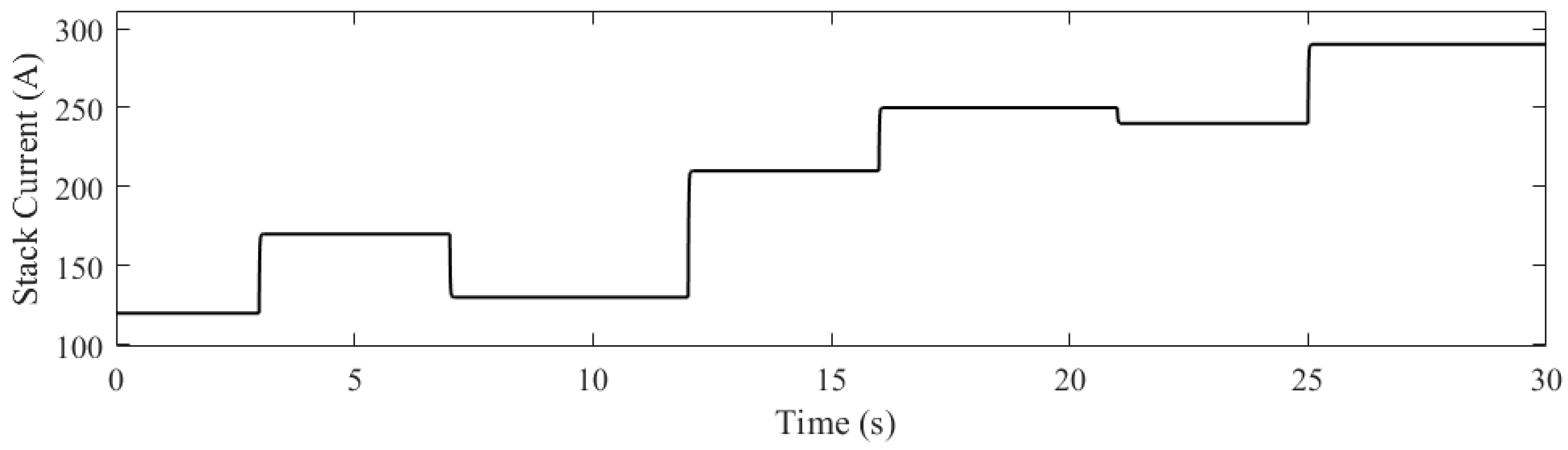
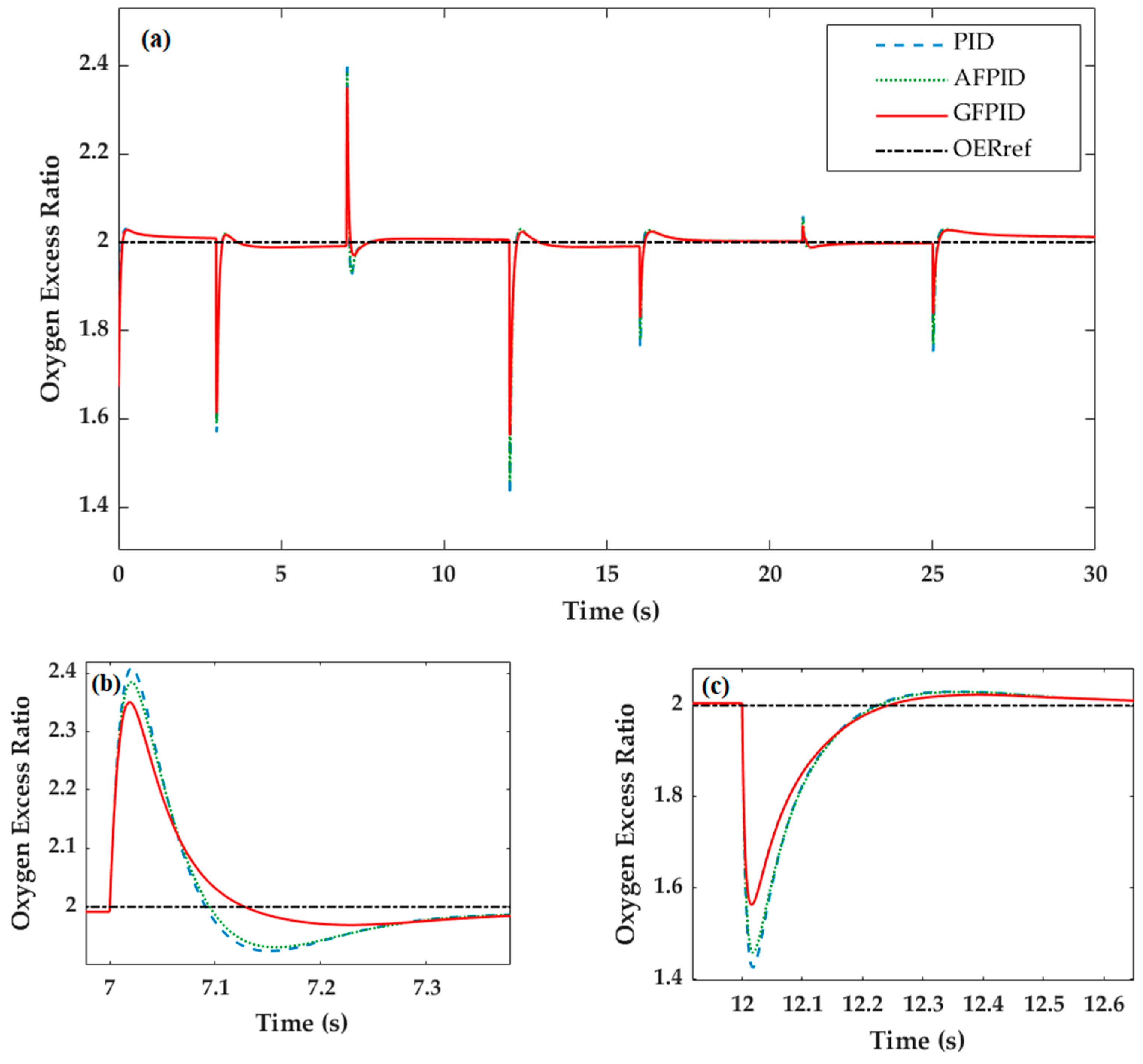
The simulation platform of this paper is MATLAB/Simulink software. The research content includes the three conventional PID, AFPID and GFPID control strategies. The reference value of oxygen excess ratio was set as 2 () to avoid oxygen starvation and optimize parasitic power. As shown in Figure 11, the stack current suddenly decreases at 7 s and increases sharply at 12 s due to the change in external load. This can simulate the system response when the input changes dramatically. Figure 12a shows the response of the oxygen excess ratio () of PEMFC at the reference value of optimal oxygen excess ratio () for the whole 30 s. Figure 12a,b respectively show the comparison of the control effects of the excess oxygen ratio under three control strategies when the current suddenly decreases at 7 s and sharply increases at 12 s. The simulation results show that the under GFPID control obtains smaller overshoot and reaches the set value significantly faster.
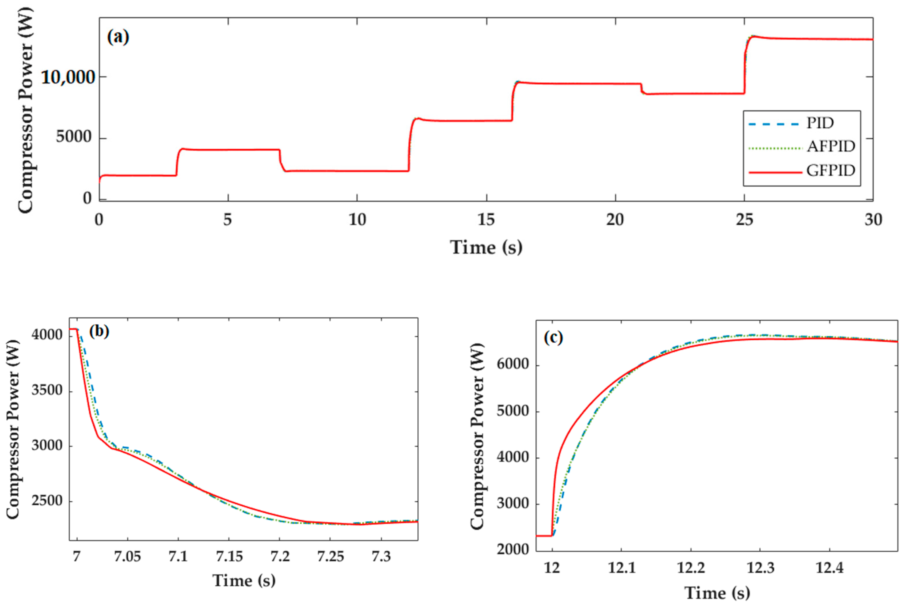
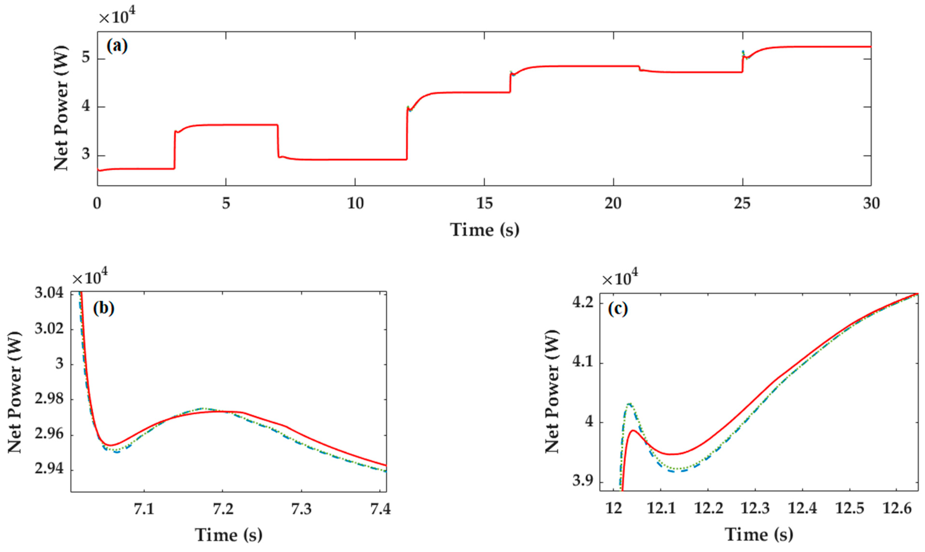
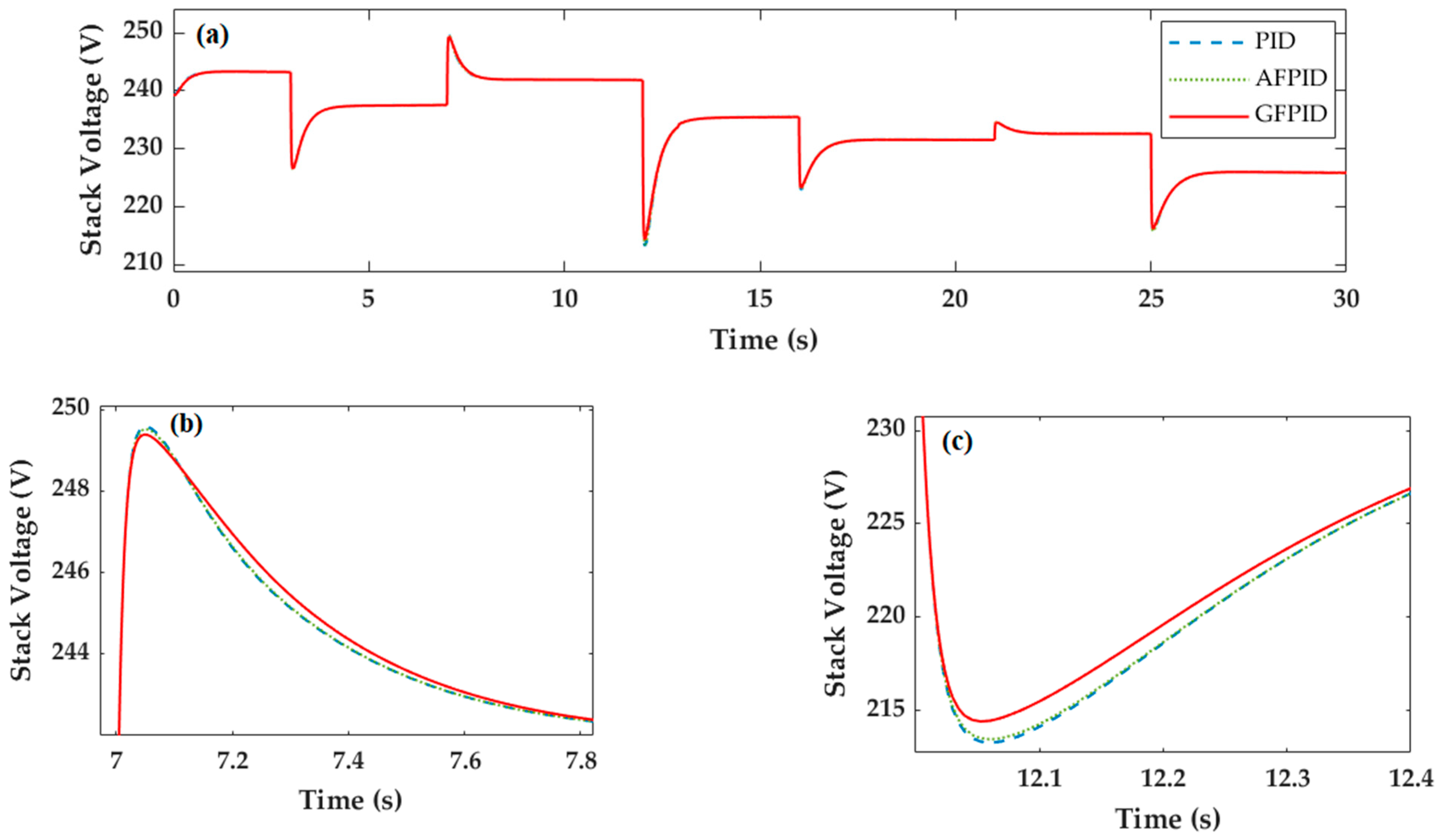
Meanwhile, the measurement indicators also perform well under GFPID control. As shown in Figure 13a, when the current drops sharply at 7 s, the compressor power, which is the main source of parasitic power, has the minimum value under GFPID control, and the result meets the expected goal. In Figure 13b, when the current of 12 s increases sharply, the compressor power has a general control effect under GFPID control. In Figure 14a,b, the net power value under GFPID control is generally higher than that of the other two control strategies. In Figure 15a,b the output value of stack voltage under GFPID control is higher than that of the other two control strategies, achieving the goal of improving fuel cell performance. By analyzing the comparison of experimental simulation, it can be seen that AFPID has better performance, but the overall control performance is not as good as GFPID. Conventional PID control is the worst.
5. Conclusions
A control-oriented PEMFC system model was proposed in this paper, which includes not only the stack model, but also the auxiliary component subsystem. Based on the control-oriented model, three control strategies were adopted, which are conventional PID, AFPID and GFPID control. The traditional PID control was first introduced in this paper. Due to the limitation of conventional PID, The AFPID controller was designed with fuzzy control to adjust the oxygen excess ratio of the fuel cell to avoid oxygen starvation, optimize parasitic power and net power. Simulation results shown that AFPID is better than conventional PID for PEMFC oxygen excess ratio control. However, in the design of a high-dimensional fuzzy controller, the number of rules generally increases exponentially with the number of input variables. Therefore, a fuzzy control method based on granular function (GFPID) was proposed in this paper. The fuzzy controller is replaced by a function generated by a granular function algorithm to optimal control. Compared with AFPID control, GFPID control achieves a better control effect. The experiment shows that the granular function fuzzy control system can be equivalent to the conventional fuzzy control system in simulation effect. The feasibility and superiority of the algorithm based on particle function were also verified.
Author Contributions
X.T. proposed the innovative ideas behind this work and the design of the method and prepared the manuscript; Z.L. and F.L. completed the simulation and result analysis; C.W. and Y.H. reviewed and revised the manuscript. All authors have read and agreed to the published version of the manuscript.
Funding
This research was funded by National Natural Science Foundation of China (Nos. 61973322).
Institutional Review Board Statement
Not applicable.
Informed Consent Statement
Not applicable.
Data Availability Statement
The data that support the findings of this study are available from the corresponding author upon request.
Acknowledgments
The authors gratefully acknowledge the financial support from National Natural Science Foundation of China (Nos. 61973322).
Conflicts of Interest
The authors declare no conflict of interest.
Nomenclature
| parametric coefficients | V | |
| specific heat capacity constant of air | J/KgK | |
| cathode water vapor concentration | mg/m3 | |
| anode water vapor concentration | mg/m3 | |
| polymer membrane diffusion coefficient | ||
| open circuit voltage | V | |
| Faraday constant | C/mole | |
| stack current | A | |
| actual current density of the fuel cell | A/m2 | |
| inertia of compressor motor | Kgm2 | |
| maximum current density of the cell | A/m2 | |
| torsional constant | Nm/A | |
| motor constant | V/(rad/s) | |
| membrane thickness | m | |
| mass of the hydrogen | Kg | |
| mass of the nitrogen | Kg | |
| mass of the oxygen | Kg | |
| mass of the water vapor | Kg | |
| air molar mass | Kg/mole | |
| hydrogen molar mass | Kg/mole | |
| oxygen molar mass | Kg/mole | |
| water vapor molar mass | Kg/mole | |
| electroosmotic drag coefficient | ||
| number of the fuel cell | ||
| internal pressure of cooler | Pa | |
| hydrogen partial pressure | Pa | |
| oxygen partial pressure | Pa | |
| atmospheric water vapor pressure | Pa | |
| water vapor pressure cooler | Pa | |
| water vapor pressure in humidifier | Pa | |
| fuel cell temperature | Kelvin | |
| cooler temperature | Kelvin | |
| atmospheric temperature | Kelvin | |
| saturation pressure at cooler temperature | Pa | |
| saturation pressure at | Pa | |
| compressor resistance | Ω | |
| compressor voltage | V | |
| inlet flow rate of oxygen | Q | |
| outlet flow rate of oxygen | Q | |
| reaction consumed rate of oxygen | Q | |
| inlet flow rate of nitrogen | Q | |
| outlet flow rate of nitrogen | Q | |
| cathode vapor inlet flow rate | Q | |
| cathode vapor outlet flow rate | Q | |
| cathode water generation flow rate | Q | |
| membrane water molecular flow rate | Q | |
| inlet flow rate of hydrogen | Q | |
| outlet flow rate of hydrogen | Q | |
| consumed rate of hydrogen | Q | |
| anode vapor inlet flow rate | Q | |
| cathode vapor outlet flow rate | Q | |
| humidifier vapor flow rate | Q | |
| cooler vapor flow rate | Q | |
| injected vapor flow rate | Q | |
| air flow rate of air compressor | Q | |
| membrane conductivity | S | |
| driving torque | Nm | |
| load torque of air compressor | Nm | |
| speed of air compressor | RPS | |
| mechanical efficiency | ||
| actual compression efficiency | ||
| specific heat capacity | J/(KgK) | |
| cooler outlet gas humidity | ||
| atmospheric humidity | ||
| humidifier outlet gas humidity |
Appendix A

Table A1.
System parameter values.
| Parameter | Unit | Value |
|---|---|---|
| 380 | ||
| K | 353 | |
| K | 298 | |
| m | ||
| Kg·m2 | ||
| Ω | 1.2 | |
| J/(Kg·K) | 1.4 | |
| N·m/A | ||
| V/(rad/s) | ||
| 0.98 |
References
- Sopian, K.; Daud, W.R.W. Challenges and future developments in proton exchange membrane fuel cells. Renew. Energy 2006, 31, 719–727. [Google Scholar] [CrossRef]
- Daud, W.; Rosli, R.; Majlan, E.; Hamid, S.; Mohamed, R.; Husaini, T. PEM fuel cell system control: A review. Renew. Energy 2017, 113, 620–638. [Google Scholar] [CrossRef]
- Thanapalan, K.K.T.; Williams, J.G.; Liu, G.P.; Rees, D. Modelling of a Pem Fuel Cell System. IFAC Proc. Vol. 2008, 41, 4636–4641. [Google Scholar] [CrossRef] [Green Version]
- Hannan, M.; Azidin, F.; Mohamed, A. Hybrid electric vehicles and their challenges: A review. Renew. Sustain. Energy Rev. 2014, 29, 135–150. [Google Scholar] [CrossRef]
- Wee, J.-H. Applications of proton exchange membrane fuel cell systems. Renew. Sustain. Energy Rev. 2007, 11, 1720–1738. [Google Scholar] [CrossRef]
- Rahimi-Gorji, M.; Ghajar, M.; Kakaee, A.-H.; Ganji, D.D. Modeling of the air conditions effects on the power and fuel consumption of the SI engine using neural networks and regression. J. Braz. Soc. Mech. Sci. Eng. 2017, 39, 375–384. [Google Scholar] [CrossRef]
- Xu, L.; Hu, J.; Cheng, S.; Fang, C.; Li, J.; Ouyang, M.; Lehnert, W. Robust control of internal states in a polymer electrolyte membrane fuel cell air-feed system by considering actuator properties. Int. J. Hydrogen Energy 2017, 42, 13171–13191. [Google Scholar] [CrossRef]
- Liu, Z.; Chen, J.; Chen, H.; Yan, C. Air supply regulation for PEMFC systems based on uncertainty and disturbance estimation. Int. J. Hydrogen Energy 2018, 43, 11559–11567. [Google Scholar] [CrossRef]
- Abdin, Z.; Webb, C.J.; Gray, E.M. PEM fuel cell model and simulation in Matlab–Simulink based on physical parameters. Energy 2016, 116, 1131–1144. [Google Scholar] [CrossRef]
- Bao, C.; Ouyang, M.; Yi, B. Modeling and control of air stream and hydrogen flow with recirculation in a PEM fuel cell system—I. Control-oriented modeling. Int. J. Hydrogen Energy 2006, 31, 1879–1896. [Google Scholar] [CrossRef]
- Sun, L.; Shen, J.; Hua, Q.; Lee, K.Y. Data-driven oxygen excess ratio control for proton exchange membrane fuel cell. Appl. Energy 2018, 231, 866–875. [Google Scholar] [CrossRef]
- Chen, J.; Liu, Z.; Wang, F.; Ouyang, Q.; Su, H. Optimal Oxygen Excess Ratio Control for PEM Fuel Cells. IEEE Trans. Control Syst. Technol. 2018, 26, 1711–1721. [Google Scholar] [CrossRef]
- Han, J.; Yu, S.; Yi, S. Oxygen excess ratio control for proton exchange membrane fuel cell using model reference adaptive control. Int. J. Hydrogen Energy 2019, 44, 18425–18437. [Google Scholar] [CrossRef]
- Zhang, H.K.; Wang, Y.F.; Wang, D.H.; Wang, Y.L. Adaptive robust control of oxygen excess ratio for PEMFC system based on type-2 fuzzy logic system. Inf. Sci. 2020, 511, 1–17. [Google Scholar] [CrossRef]
- Danzer, M.A.; Wittmann, S.J.; Hofer, E.P. Prevention of fuel cell starvation by model predictive control of pressure, excess ratio, and current. J. Power Sources 2009, 190, 86–91. [Google Scholar] [CrossRef]
- Chen, Q.; Gao, L.; Dougal, R.A.; Quan, S. Multiple model predictive control for a hybrid proton exchange membrane fuel cell system. J. Power Sources 2009, 191, 473–482. [Google Scholar] [CrossRef]
- Deng, H.; Li, Q.; Cui, Y.; Zhu, Y.; Chen, W. Nonlinear controller design based on cascade adaptive sliding mode control for PEM fuel cell air supply systems. Int. J. Hydrogen Energy 2019, 44, 19357–19369. [Google Scholar] [CrossRef]
- Ma, Y.; Zhang, F.; Gao, J.; Chen, H.; Shen, T. Oxygen excess ratio control of PEM fuel cells using observer-based nonlinear triple-step controller. Int. J. Hydrogen Energy 2020, 45, 29705–29717. [Google Scholar] [CrossRef]
- Thomya, A.; Khunatorn, Y. Design of Control System of Hydrogen and Oxygen Flow Rate for Proton Exchange Membrane Fuel Cell Using Fuzzy Logic Controller. Energy Procedia 2011, 9, 186–197. [Google Scholar] [CrossRef] [Green Version]
- Rakhtala, S.; Roudbari, E.S. Fuzzy PID control of a stand-alone system based on PEM fuel cell. Int. J. Electr. Power Energy Syst. 2016, 78, 576–590. [Google Scholar] [CrossRef]
- Benchouia, N.E.; Derghal, A.; Mahmah, B.; Madi, B.; Khochemane, L.; Aoul, E.H. An adaptive fuzzy logic controller (AFLC) for PEMFC fuel cell. Int. J. Hydrogen Energy 2015, 40, 13806–13819. [Google Scholar] [CrossRef]
- Yao, J.T.; Vasilakos, A.V.; Pedrycz, W. Granular Computing: Perspectives and Challenges. IEEE Trans. Cybern. 2013, 43, 1977–1989. [Google Scholar] [CrossRef] [PubMed]
- Niu, J.; Huang, C.; Li, J.; Fan, M. Parallel computing techniques for concept-cognitive learning based on granular computing. Int. J. Mach. Learn. Cybern. 2018, 9, 1785–1805. [Google Scholar] [CrossRef]
- Yao, Y. Three-way decision and granular computing. Int. J. Approx. Reason. 2018, 103, 107–123. [Google Scholar] [CrossRef]
- Özbek, M.; Wang, S.; Marx, M.; Söffker, D. Modeling and control of a PEM fuel cell system: A practical study based on experimental defined component behavior. J. Process Control 2013, 23, 282–293. [Google Scholar] [CrossRef]
- Amphlett, J.C.; Baumert, R.M.; Mann, R.F.; Peppley, B.A.; Roberge, P.R.; Harris, T.J. Performance Modeling of the Ballard Mark IV Solid Polymer Electrolyte Fuel Cell: I. Mechanistic Model Development. J. Electrochem. Soc. 1995, 142, 1. [Google Scholar] [CrossRef]
- Kim, J.; Lee, S.; Srinivasan, S.; Chamberlin, C. Modeling of proton exchange membrane fuel cell performance with an empirical equation. J. Electrochem. Soc. 1995, 142, 2670–2674. [Google Scholar] [CrossRef]
- Cheng, J.; Zhang, G. Parameter fitting of PEMFC models based on adaptive differential evolution. Int. J. Electr. Power Energy Syst. 2014, 62, 189–198. [Google Scholar] [CrossRef]
Figure 1.
Distribution diagram of proton exchange membrane fuel cell (PEMFC) system architecture.

Figure 2.
The adaptive fuzzy PID control framework of PEMFC.

Figure 3.
The adaptive fuzzy PID controller architecture.

Figure 4.
Membership functions of and

Figure 5.
Membership functions of

Figure 6.
Fuzzy logic controller surface: (a) surface of ; (b) surface of ; (c) surface of

Figure 7.
The granular function fuzzy PID control architecture.

Figure 8.
The fitting surface of the granular function.

Figure 9.
The fitting surface of the granular function.

Figure 10.
The fitting surface of the granular function.

Figure 11.
PEMFC parameters: stack current.

Figure 12.
Response of at constant : (a) comparison of simulation; (b) zoom in current step-down at 7 s; (c) zoom in current step-up at 12 s.
Figure 12.
Response of at constant : (a) comparison of simulation; (b) zoom in current step-down at 7 s; (c) zoom in current step-up at 12 s.

Figure 13.
PEMFC parameters: (a) 30 s of compressor power; (b) compressor power at 7 s; (c) compressor power at 12 s.
Figure 13.
PEMFC parameters: (a) 30 s of compressor power; (b) compressor power at 7 s; (c) compressor power at 12 s.

Figure 14.
PEMEC parameters: (a) 30 s of net power; (b) net power at 7 s; (c) net power at 12 s.

Figure 15.
PEMFC parameters: (a) 30 s of stack voltage; (b) stack voltage at 7 s; (c) stack voltage at 12 s.
Figure 15.
PEMFC parameters: (a) 30 s of stack voltage; (b) stack voltage at 7 s; (c) stack voltage at 12 s.

Table 1.
Ziegler–Nichols method for control parameter setting.
| Control Strategy | |||
|---|---|---|---|
| P (Proportion) | - | - | |
| PI (Proportion Integration) | - | ||
| PID (Proportion Integration Differentiation) |
Table 2.
Fuzzy control rule for .
| NB | NM | NS | NZ | PZ | PS | PM | PB | |
|---|---|---|---|---|---|---|---|---|
| NB | NB | NB | NB | PS | NB | NM | Z | Z |
| NM | NB | NM | NM | PS | NM | NS | Z | PM |
| NS | NB | NM | NS | PS | NS | NS | PB | PB |
| Z | NB | NM | Z | Z | Z | Z | PM | PB |
| PS | NB | NB | PS | NS | PS | PS | PM | PB |
| PM | NM | Z | PS | NM | PS | PM | PM | PB |
| PB | Z | Z | PM | NB | PS | PB | PB | PB |
Table 3.
Fuzzy control rule for .
| NB | NM | NS | Z | PS | PM | PB | |
|---|---|---|---|---|---|---|---|
| NB | NB | NM | NB | NM | NM | Z | Z |
| NM | NB | NM | NM | NS | NS | Z | PM |
| NS | NB | NM | NS | Z | Z | PB | PB |
| Z | NB | NM | NS | Z | PS | PM | PB |
| PS | NB | NB | Z | Z | PS | PM | PB |
| PM | NM | Z | PS | NS | PM | PM | PB |
| PB | Z | Z | PM | NM | PB | PM | PB |
Table 4.
Fuzzy control rule for .
| NB | NM | NS | Z | PS | PM | PB | |
|---|---|---|---|---|---|---|---|
| NB | PS | PS | ZO | ZO | ZO | PS | PS |
| NM | NB | NB | NM | NM | PM | PB | PB |
| NS | NB | NB | NM | NS | PS | PS | PM |
| Z | NS | NB | NS | NS | ZO | PS | PM |
| PS | NB | NS | NM | NS | PS | PB | PB |
| PM | NB | PS | NM | NS | ZO | PB | PB |
| PB | PS | PS | ZO | ZO | PS | PS | PS |
Table 5.
Fifth-order fitting granular function coefficient for.
| Coefficient | Value | Coefficient | Value | Coefficient | Value |
|---|---|---|---|---|---|
| −2.096 | −8.462 | −1.349 | |||
| 4.671 | −1.067 | 0.4124 | |||
| 4.136 | 3.133 | 0.5587 | |||
| 2.769 | −2.344 | −2.901 | |||
| −1.449 | 2.255 | 5.731 | |||
| 2.693 | −1.304 | −0.05686 | |||
| 2.893 | 0.6139 | −2.436 |
Publisher’s Note: MDPI stays neutral with regard to jurisdictional claims in published maps and institutional affiliations. |
© 2021 by the authors. Licensee MDPI, Basel, Switzerland. This article is an open access article distributed under the terms and conditions of the Creative Commons Attribution (CC BY) license (http://creativecommons.org/licenses/by/4.0/).
Share and Cite
MDPI and ACS Style
Tang, X.; Wang, C.; Hu, Y.; Liu, Z.; Li, F. Adaptive Fuzzy PID Based on Granular Function for Proton Exchange Membrane Fuel Cell Oxygen Excess Ratio Control. Energies 2021, 14, 1140. https://0-doi-org.brum.beds.ac.uk/10.3390/en14041140
AMA Style
Tang X, Wang C, Hu Y, Liu Z, Li F. Adaptive Fuzzy PID Based on Granular Function for Proton Exchange Membrane Fuel Cell Oxygen Excess Ratio Control. Energies. 2021; 14(4):1140. https://0-doi-org.brum.beds.ac.uk/10.3390/en14041140
Chicago/Turabian StyleTang, Xiao, Chunsheng Wang, Yukun Hu, Zijian Liu, and Feiliang Li. 2021. "Adaptive Fuzzy PID Based on Granular Function for Proton Exchange Membrane Fuel Cell Oxygen Excess Ratio Control" Energies 14, no. 4: 1140. https://0-doi-org.brum.beds.ac.uk/10.3390/en14041140
Note that from the first issue of 2016, this journal uses article numbers instead of page numbers. See further details here.