
Intensifying the Charging Response of a Phase-Change Material with Twisted Fin Arrays in a Shell-And-Tube Storage System

 ,
,  ,
,  ,
,  , , , and
Abstract
:1. Introduction
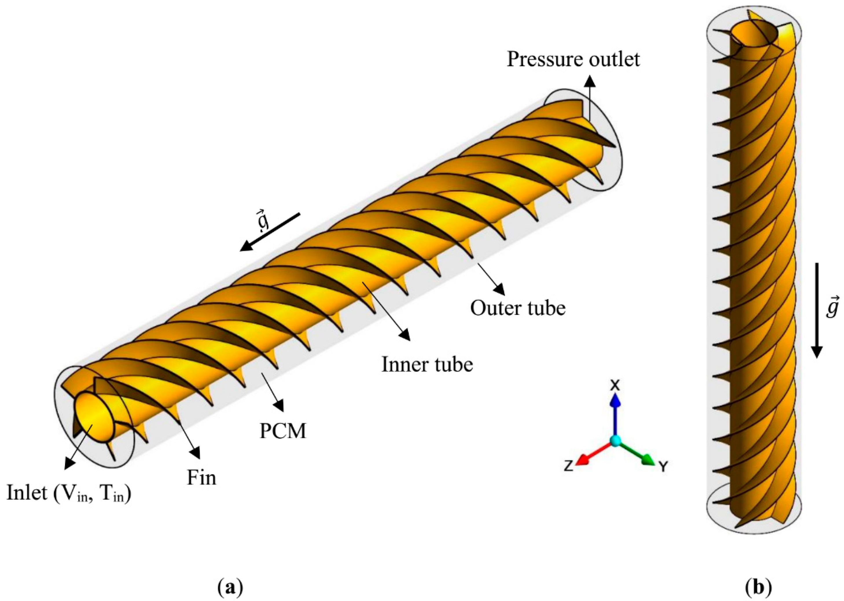
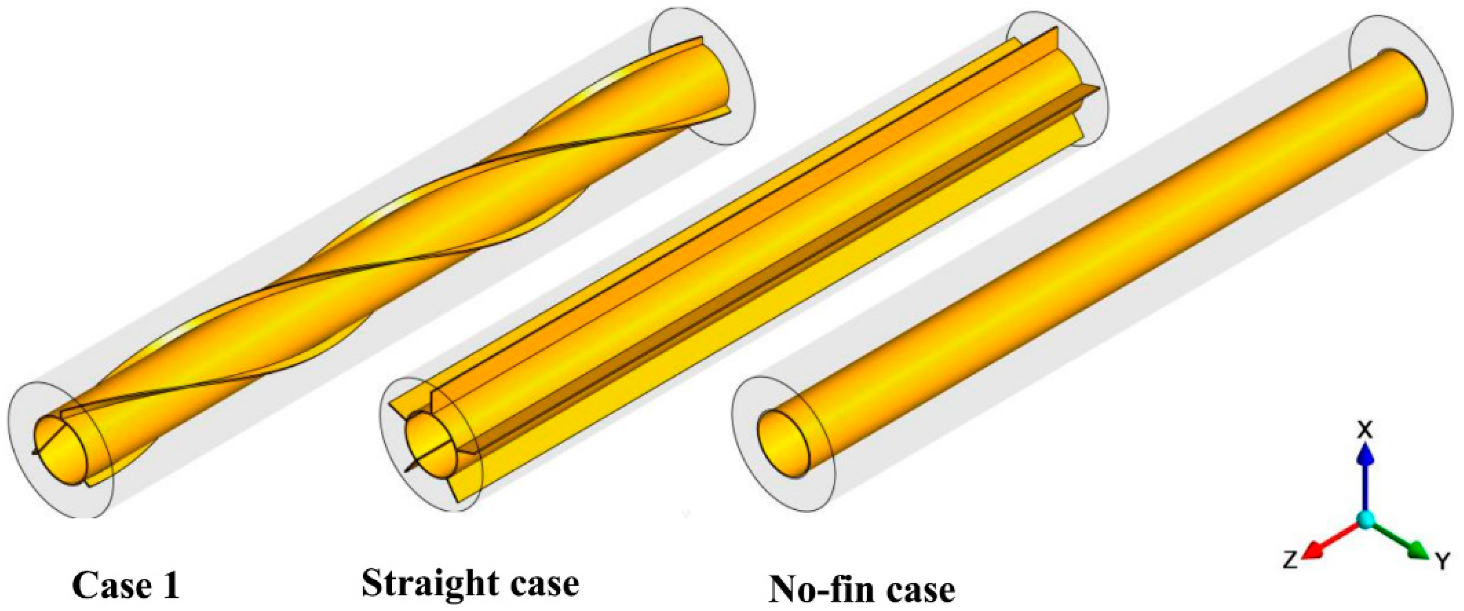
2. Geometry and Boundary Conditions
3. Mathematical Modeling
- Boussinesq approximation for the buoyancy effect.
- The transient, Newtonian, and laminar fluid flow of liquid PCM
- Neglecting viscous dissipation
- Volume expansion is neglected [37]
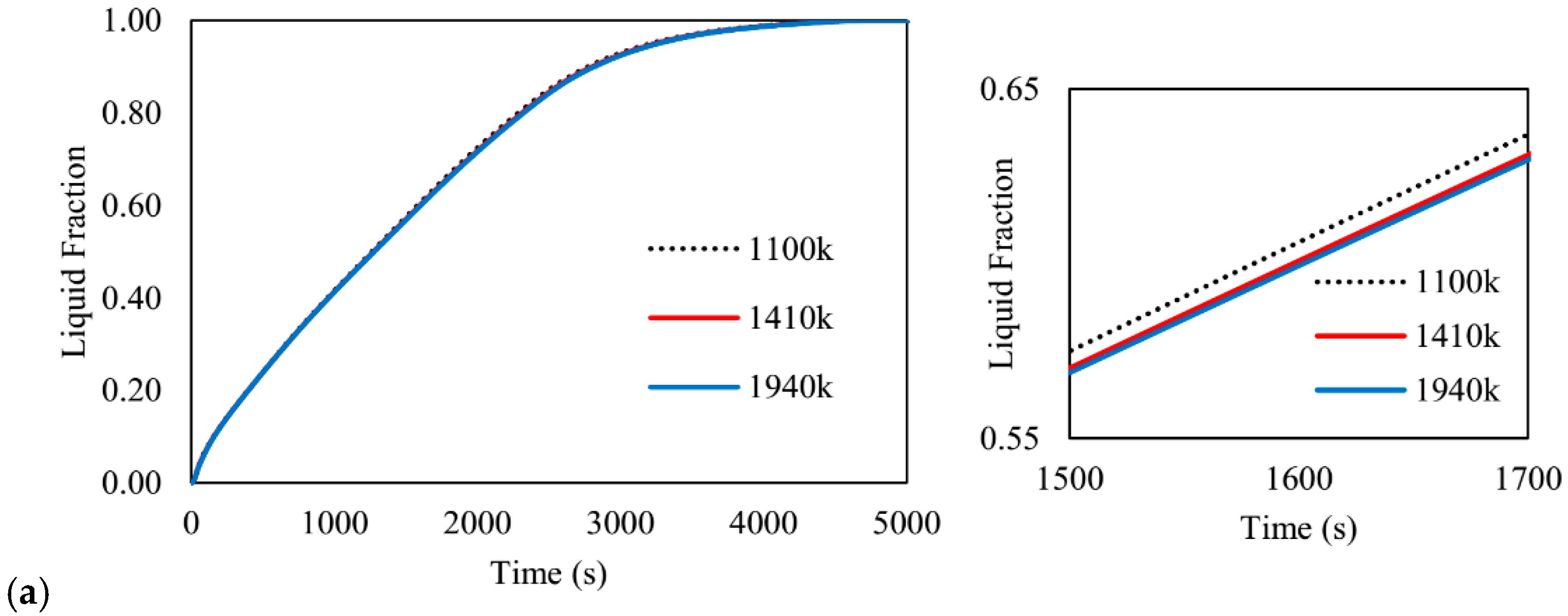
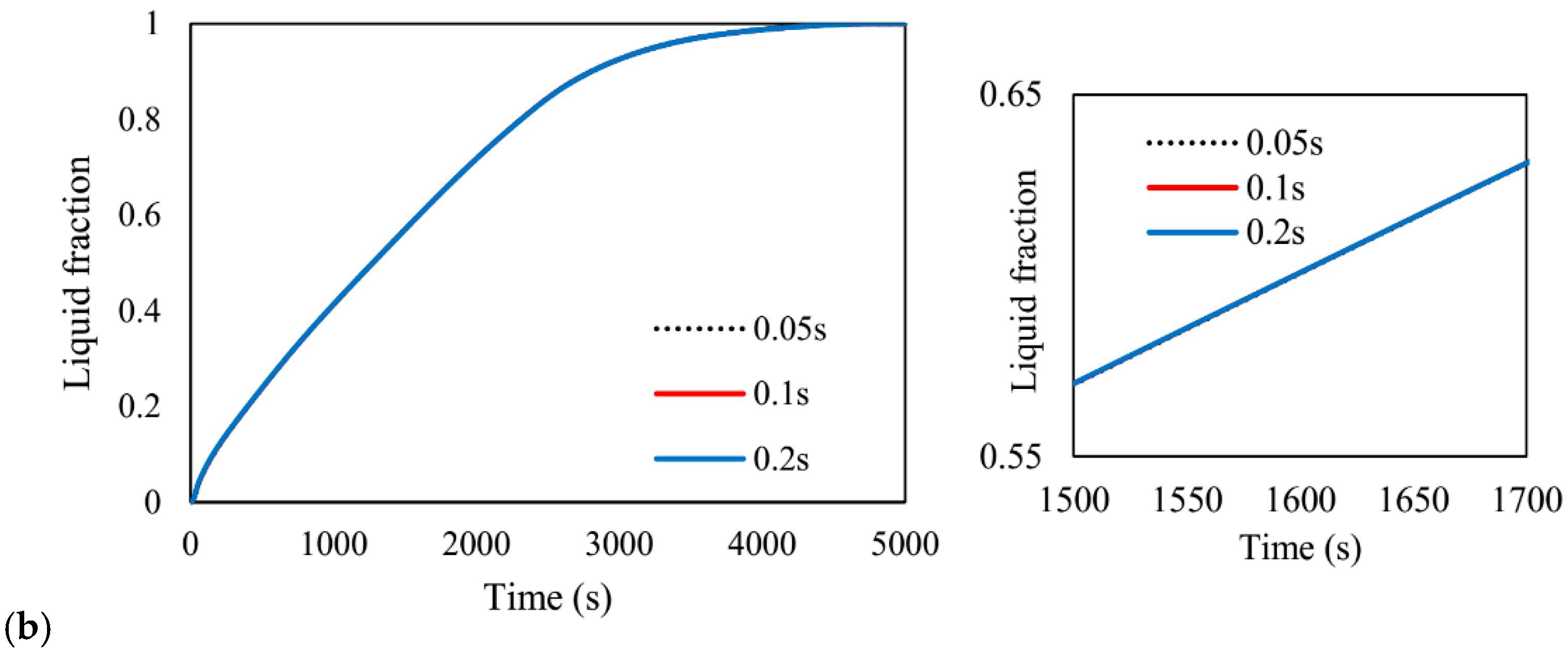
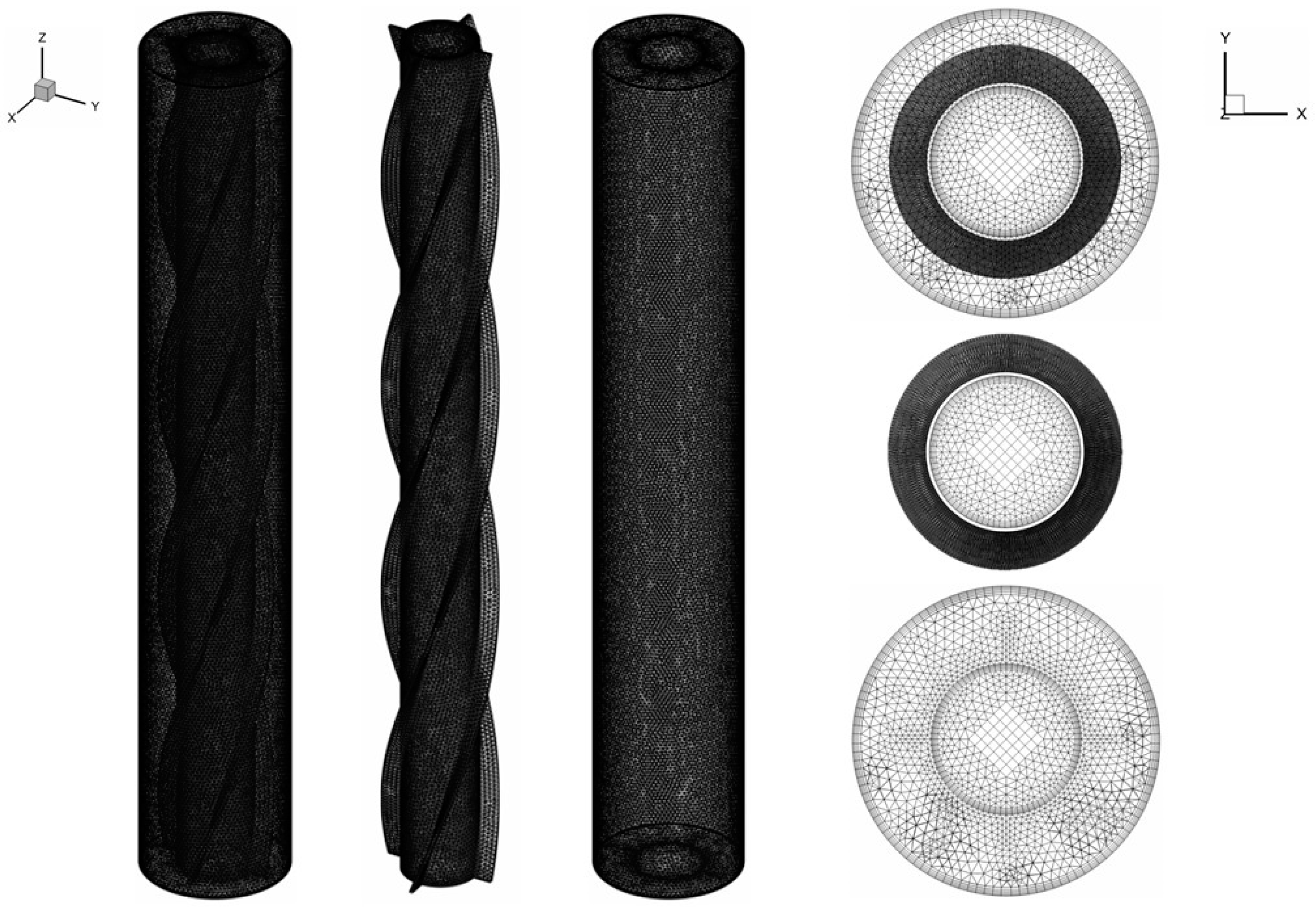
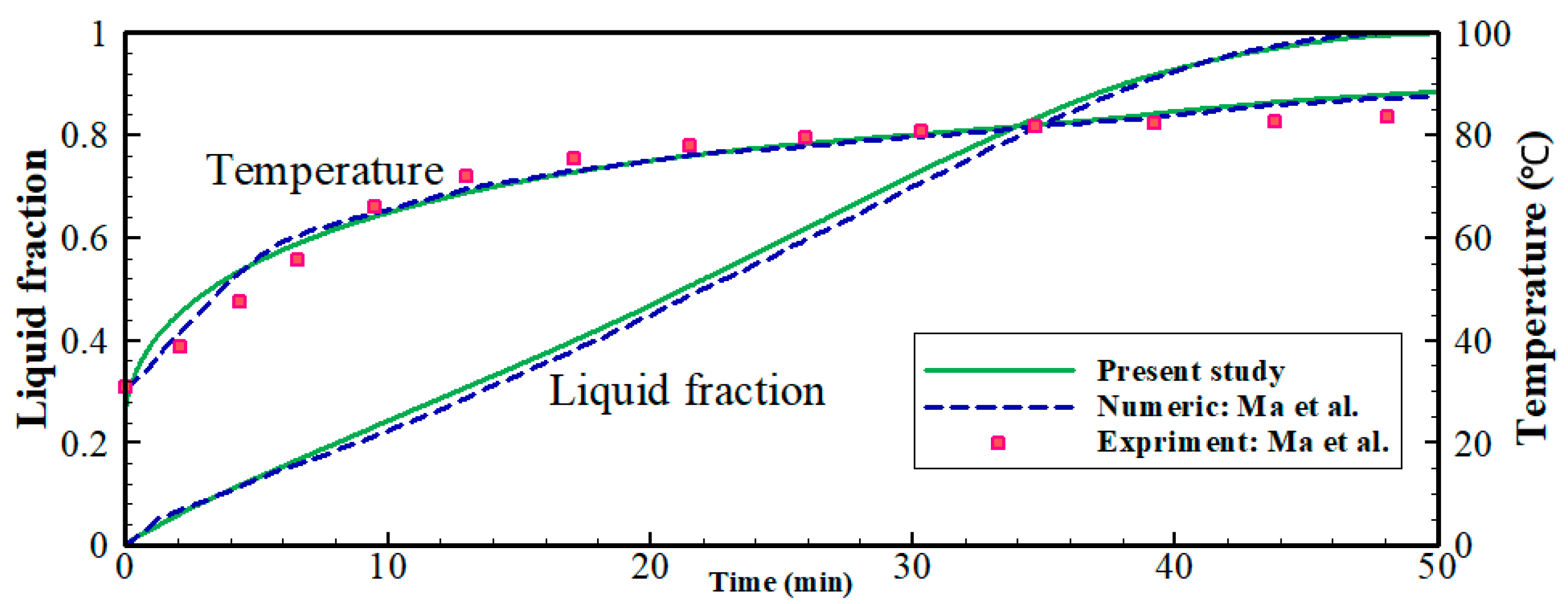
4. Numerical Modeling and Validation
5. Results and Discussion
5.1. Part A
5.2. Part B
6. Conclusions
Author Contributions
Funding
Institutional Review Board Statement
Informed Consent Statement
Data Availability Statement
Conflicts of Interest
Abbreviations
| Nomenclature | |||
| Am | Constant for mush source term | tm(s) | Melting time |
| Cp (Jkg−1K−1) | Specific heat capacity | T (K) | Temperature |
| g (ms−2) | Gravity | Te(K) | End temperature |
| H (kJ/mol) | Enthalpy | Ti (K) | Initial temperature |
| Hfin (mm) | Height of fins | Tin (K) | Inlet temperature |
| k (Wm−1K−1) | Thermal conductivity | (m/s) | Velocity |
| LF | Liquid fraction–Melt fraction | (m/s) | Inlet velocity |
| Nfin | Number of fins | ||
| m (kg) | Mass | Greek symbols | |
| P (W) | Power | β (K−1)λ | Expansion coefficient |
| Pitch | Fin’s pitch | λμ (kgm−1s−1) | Expansion coefficient |
| Q (J) | Capacity of heat storage | μ (kgm−1s−1)ρ (kgm−3) | Liquid fraction |
| (W) | Rate of stored heat | ρ (kgm−3)ΔH (Jkg−1) | Dynamic Viscosity |
| tfin (mm) | Thickness of fins | ΔH (Jkg−1) | Density |
| TL (K) | Temperature (Liquidus) | Stored latent heat energy | |
| Ts (K) | Temperature (Solidus) | ||
References
- Liao, Z.; Xu, C.; Ren, Y.; Gao, F.; Ju, X.; Du, X. A novel effective thermal conductivity correlation of the PCM melting in spherical PCM encapsulation for the packed bed TES system. Appl. Therm. Eng. 2018. [Google Scholar] [CrossRef]
- Al-Jethelah, M.; Tasnim, S.H.; Mahmud, S.; Dutta, A. Nano-PCM filled energy storage system for solar-thermal applications. Renew. Energy 2018. [Google Scholar] [CrossRef]
- Ebadi, S.; Tasnim, S.H.; Aliabadi, A.A.; Mahmud, S. Melting of nano-PCM inside a cylindrical thermal energy storage system: Numerical study with experimental verification. Energy Convers. Manag. 2018, 166, 241–259. [Google Scholar] [CrossRef]
- Mahdi, J.M.; Nsofor, E.C. Solidification of a PCM with nanoparticles in triplex-tube thermal energy storage system. Appl. Therm. Eng. 2016, 108, 596–604. [Google Scholar] [CrossRef]
- Mahdi, J.M.; Nsofor, E.C. Melting of PCM with Nanoparticles in a Triplex-Tube Thermal Energy Storage System. Ashrae Trans. 2016, 122, 215–224. [Google Scholar]
- Shanan, Z.J.; Hadi, S.M.; Shanshool, S.K. Structural analysis of chemical and green synthesis of cuo nanoparticles and their effect on biofilm formation. Baghdad Sci. J. 2018, 15, 211–216. [Google Scholar] [CrossRef]
- Sheikholeslami, M.; Lohrasbi, S.; Ganji, D.D. Numerical analysis of discharging process acceleration in LHTESS by immersing innovative fin configuration using finite element method. Appl. Therm. Eng. 2016, 107, 154–166. [Google Scholar] [CrossRef]
- Lohrasbi, S.; Sheikholeslami, M.; Ganji, D.D. Discharging process expedition of NEPCM in fin-assisted latent heat thermal energy storage system. J. Mol. Liq. 2016, 221, 833–841. [Google Scholar] [CrossRef]
- Mahdi, J.M.; Nsofor, E.C. Melting enhancement in triplex-tube latent thermal energy storage system using nanoparticles-fins combination. Int. J. Heat Mass Transf. 2017, 109, 417–427. [Google Scholar] [CrossRef]
- Mahdi, J.M.; Nsofor, E.C. Solidification enhancement of PCM in a triplex-tube thermal energy storage system with nanoparticles and fins. Appl. Energy 2018, 211, 975–986. [Google Scholar] [CrossRef]
- Deng, Z.; Liu, X.; Zhang, C.; Huang, Y.; Chen, Y. Melting behaviors of PCM in porous metal foam characterized by fractal geometry. Int. J. Heat Mass Transf. 2017, 113, 1031–1042. [Google Scholar] [CrossRef]
- Mahdi, J.M.; Nsofor, E.C. Melting enhancement in triplex-tube latent heat energy storage system using nanoparticles-metal foam combination. Appl. Energy 2017, 191, 22–34. [Google Scholar] [CrossRef]
- Mahdi, J.M.; Nsofor, E.C. Solidification enhancement in a triplex-tube latent heat energy storage system using nanoparticles-metal foam combination. Energy 2017, 126, 501–512. [Google Scholar] [CrossRef]
- Mahdi, J.M.; Mohammed, H.I.; Hashim, E.T.; Talebizadehsardari, P.; Nsofor, E.C. Solidification enhancement with multiple PCMs, cascaded metal foam and nanoparticles in the shell-and-tube energy storage system. Appl. Energy 2020, 257, 113993. [Google Scholar] [CrossRef]
- Mohammed, H.I.; Talebizadehsardari, P.; Mahdi, J.M.; Arshad, A.; Sciacovelli, A.; Giddings, D. Improved melting of latent heat storage via porous medium and uniform Joule heat generation. J. Energy Storage 2020, 31, 101747. [Google Scholar] [CrossRef]
- Abdulateef, A.M.; Mat, S.; Abdulateef, J.; Sopian, K.; Al-Abidi, A.A. Geometric and design parameters of fins employed for enhancing thermal energy storage systems: A review. Renew. Sustain. Energy Rev. 2018, 82, 1620–1635. [Google Scholar] [CrossRef]
- Mat, S.; Al-Abidi, A.A.; Sopian, K.; Sulaiman, M.Y.; Mohammad, A.T. Enhance heat transfer for PCM melting in triplex tube with internal–external fins. Energy Convers. Manag. 2013, 74, 223–236. [Google Scholar] [CrossRef]
- Rathod, M.K.; Banerjee, J. Thermal performance enhancement of shell and tube Latent Heat Storage Unit using longitudinal fins. Appl. Therm. Eng. 2015, 75, 1084–1092. [Google Scholar] [CrossRef]
- Abdulateef, A.M.; Mat, S.; Sopian, K.; Abdulateef, J.; Gitan, A.A. Experimental and computational study of melting phase-change material in a triplex tube heat exchanger with longitudinal/triangular fins. Sol. Energy 2017, 155, 142–153. [Google Scholar] [CrossRef]
- Mahdi, J.M.; Lohrasbi, S.; Ganji, D.D.; Nsofor, E.C. Accelerated melting of PCM in energy storage systems via novel configuration of fins in the triplex-tube heat exchanger. Int. J. Heat Mass Transf. 2018, 124, 663–676. [Google Scholar] [CrossRef]
- Mahdi, J.M.; Lohrasbi, S.; Ganji, D.D.; Nsofor, E.C. Simultaneous energy storage and recovery in the triplex-tube heat exchanger with PCM, copper fins and Al2O3 nanoparticles. Energy Convers. Manag. 2019, 180, 949–961. [Google Scholar] [CrossRef]
- Yang, X.; Guo, J.; Yang, B.; Cheng, H.; Wei, P.; He, Y.-L. Design of non-uniformly distributed annular fins for a shell-and-tube thermal energy storage unit. Appl. Energy 2020, 279, 115772. [Google Scholar] [CrossRef]
- Sciacovelli, A.; Gagliardi, F.; Verda, V. Maximization of performance of a PCM latent heat storage system with innovative fins. Appl. Energy 2015, 137, 707–715. [Google Scholar] [CrossRef]
- Zhang, C.; Li, J.; Chen, Y. Improving the energy discharging performance of a latent heat storage (LHS) unit using fractal-tree-shaped fins. Appl. Energy 2020, 259, 114102. [Google Scholar] [CrossRef]
- Konan, H.C.; Cetkin, E. Snowflake shaped high-conductivity inserts for heat transfer enhancement. Int. J. Heat Mass Transf. 2018, 127, 473–482. [Google Scholar] [CrossRef]
- Pizzolato, A.; Sharma, A.; Maute, K.; Sciacovelli, A.; Verda, V. Design of effective fins for fast PCM melting and solidification in shell-and-tube latent heat thermal energy storage through topology optimization. Appl. Energy 2017, 208, 210–227. [Google Scholar] [CrossRef]
- Yıldız, Ç.; Arıcı, M.; Nižetić, S.; Shahsavar, A. Numerical investigation of natural convection behavior of molten PCM in an enclosure having rectangular and tree-like branching fins. Energy 2020, 207, 118223. [Google Scholar] [CrossRef]
- Yu, C.; Wu, S.; Huang, Y.; Yao, F.; Liu, X. Charging performance optimization of a latent heat storage unit with fractal tree-like fins. J. Energy Storage 2020, 30, 101498. [Google Scholar] [CrossRef]
- Lin, W.; Ma, Z. Using Taguchi-Fibonacci search method to optimize phase change materials enhanced buildings with integrated solar photovoltaic thermal collectors. Energy 2016, 106, 23–37. [Google Scholar] [CrossRef]
- Xie, J.; Yuan, C. Parametric study of ice thermal storage system with thin layer ring by Taguchi method. Appl. Therm. Eng. 2016, 98, 246–255. [Google Scholar] [CrossRef] [Green Version]
- Ren, H.; Lin, W.; Ma, Z.; Fan, W.; Wang, X. Thermal performance evaluation of an integrated photovoltaic thermal-phase change material system using Taguchi method. Energy Procedia 2017, 121, 118–125. [Google Scholar] [CrossRef]
- Lin, W.; Ma, Z.; Ren, H.; Gschwander, S.; Wang, S. Multi-objective optimisation of thermal energy storage using phase change materials for solar air systems. Renew. Energy 2019, 130, 1116–1129. [Google Scholar] [CrossRef]
- Kolioak, Y.; Radhakrishna, M.; Prasad, A. Optimization of Heat Energy Based on Phase Change Materials used in Solar Collector using Taguchi Method. Mater. Today Proc. 2020, 22, 2404–2411. [Google Scholar] [CrossRef]
- Zhang, C.; Sun, Q.; Chen, Y. Solidification behaviors and parametric optimization of finned shell-tube ice storage units. Int. J. Heat Mass Transf. 2020, 146, 118836. [Google Scholar] [CrossRef]
- Talebizadeh Sardari, P.; Walker, G.S.; Gillott, M.; Grant, D.; Giddings, D. Numerical modelling of phase change material melting process embedded in porous media: Effect of heat storage size. Proc. Inst. Mech. Eng. Part A J. Power Energy 2019. [Google Scholar] [CrossRef]
- Shahsavar, A.; Majidzadeh, A.H.; Mahani, R.B.; Talebizadehsardari, P. Entropy and Thermal performance Analysis of PCM Melting and Solidification Mechanisms in a Wavy Channel Triplex-Tube Heat Exchanger. Renew. Energy 2021. [Google Scholar] [CrossRef]
- Talebizadehsardari, P.; Mohammed, H.I.; Mahdi, J.M.; Gillott, M.; Walker, G.S.; Grant, D.; Giddings, D. Effect of airflow channel arrangement on the discharge of a composite metal foam-phase change material heat exchanger. Int. J. Energy Res. 2020. [Google Scholar] [CrossRef]
- Ye, W.-B.; Zhu, D.-S.; Wang, N. Numerical simulation on phase-change thermal storage/release in a plate-fin unit. Appl. Therm. Eng. 2011, 31, 3871–3884. [Google Scholar] [CrossRef]
- Assis, E.; Katsman, L.; Ziskind, G.; Letan, R. Numerical and experimental study of melting in a spherical shell. Int. J. Heat Mass Transf. 2007, 50, 1790–1804. [Google Scholar] [CrossRef]
- Sardari, P.T.; Giddings, D.; Grant, D.; Gillott, M.; Walker, G.S. Discharge of a composite metal foam/phase change material to air heat exchanger for a domestic thermal storage unit. Renew. Energy 2019. [Google Scholar] [CrossRef]
- Al-Abidi, A.A.; Mat, S.; Sopian, K.; Sulaiman, M.Y.; Mohammad, A.T. Internal and external fin heat transfer enhancement technique for latent heat thermal energy storage in triplex tube heat exchangers. Appl. Therm. Eng. 2013, 53, 147–156. [Google Scholar] [CrossRef]
- Shahsavar, A.; Goodarzi, A.; Mohammed, H.I.; Shirneshan, A.; Talebizadehsardari, P. Thermal performance evaluation of non-uniform fin array in a finned double-pipe latent heat storage system. Energy 2020, 193, 116800. [Google Scholar] [CrossRef]
- Xu, Y.; Ren, Q.; Zheng, Z.-J.; He, Y.-L. Evaluation and optimization of melting performance for a latent heat thermal energy storage unit partially filled with porous media. Appl. Energy 2017, 193, 84–95. [Google Scholar] [CrossRef]


| Property | μ [N · s/m2] | β [1/K] | Cp [kJ/kg · K] | k [W/m · K] | ρ [kg/m3] | Lf [kJ/kg] | TL [°C] | Ts [°C] |
|---|---|---|---|---|---|---|---|---|
| values | 0.023 | 0.0006 | 2.0 | 0.2 | 815 | 170 | 35 | 29 |
| Factors | Description | Level 1 | Level 2 | Level 3 |
|---|---|---|---|---|
| A | Pitch (fin’s pitch) | 1 | 2 | 3 |
| B | Nfin (number of fins) | 3 | 4 | 5 |
| C | tfin (mm) (the fin’s thickness) | 0.5 | 1 | 1.5 |
| D | Hfin (mm) (fin’s height) | 2.5 | 5 | 7.5 |
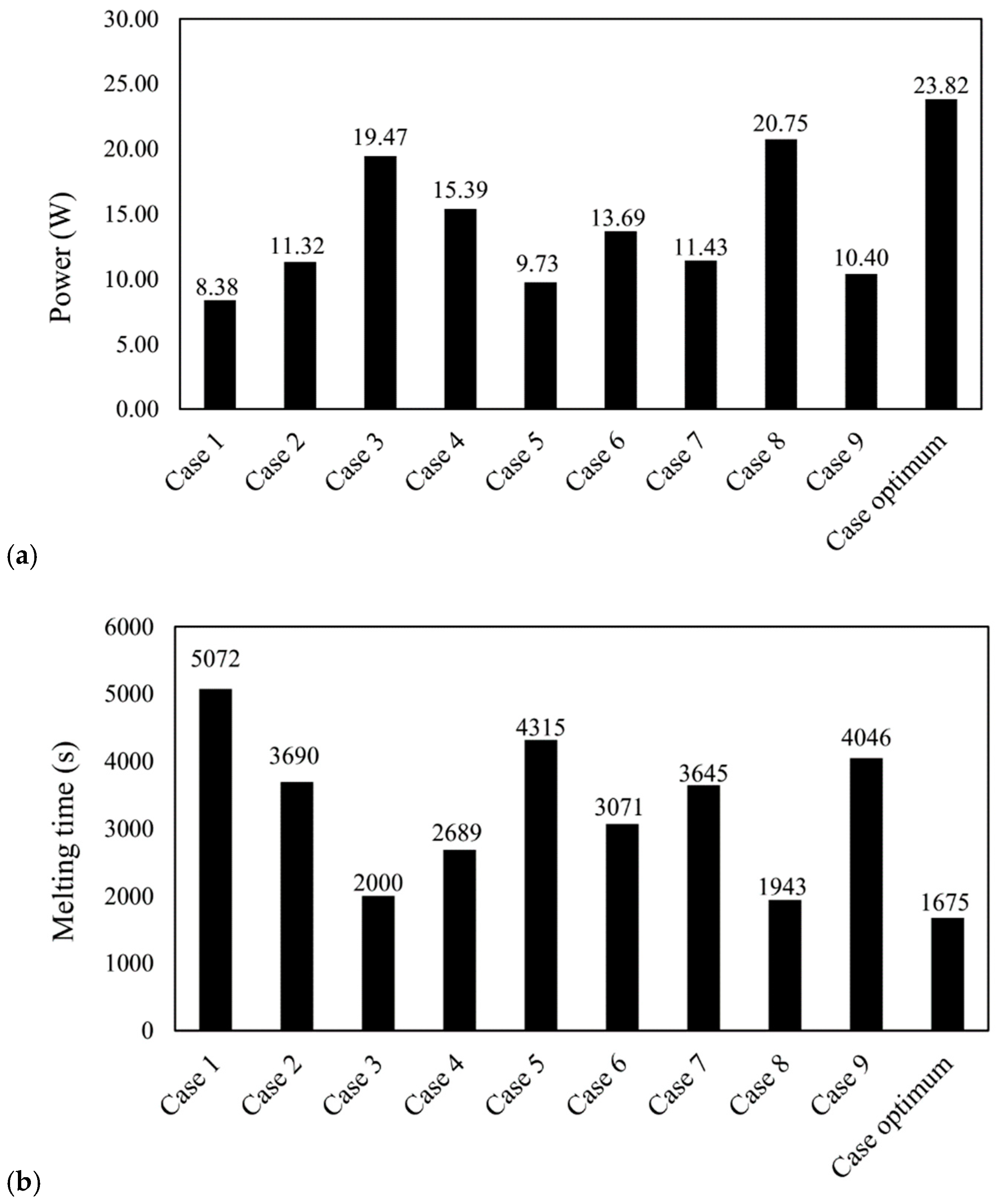
| Case | Pitch | Nfin | tfin (mm) | Hfin (mm) | PCM Mass (kg) | Melting Time (s) | Power (W) | SNR |
|---|---|---|---|---|---|---|---|---|
| 1 | 1 | 3 | 0.5 | 2.5 | 0.18676 | 5072 | 8.38 | 18.4649 |
| 2 | 1 | 4 | 1 | 5 | 0.18369 | 3690 | 11.32 | 21.0769 |
| 3 | 1 | 5 | 1.5 | 7.5 | 0.17667 | 2000 | 19.47 | 25.7873 |
| 4 | 2 | 3 | 1 | 7.5 | 0.18314 | 2689 | 15.39 | 23.7448 |
| 5 | 2 | 4 | 1.5 | 2.5 | 0.18461 | 4315 | 9.73 | 19.7623 |
| 6 | 2 | 5 | 0.5 | 5 | 0.18508 | 3071 | 13.69 | 22.7281 |
| 7 | 3 | 3 | 1.5 | 5 | 0.18316 | 3645 | 11.43 | 21.1609 |
| 8 | 3 | 4 | 0.5 | 7.5 | 0.18402 | 1943 | 20.75 | 26.3404 |
| 9 | 3 | 5 | 1 | 2.5 | 0.18507 | 4046 | 10.40 | 20.3407 |
| Optimum | 3 | 5 | 0.5 | 7.5 | 0.18388 | 1675 | 23.82 | - |
| Straight | - | 5 | 0.5 | 7.5 | 0.18386 | 2864 | 14.58 | - |
| Without Fin | - | - | - | - | 0.18755 | 5806 | 7.34 | - |
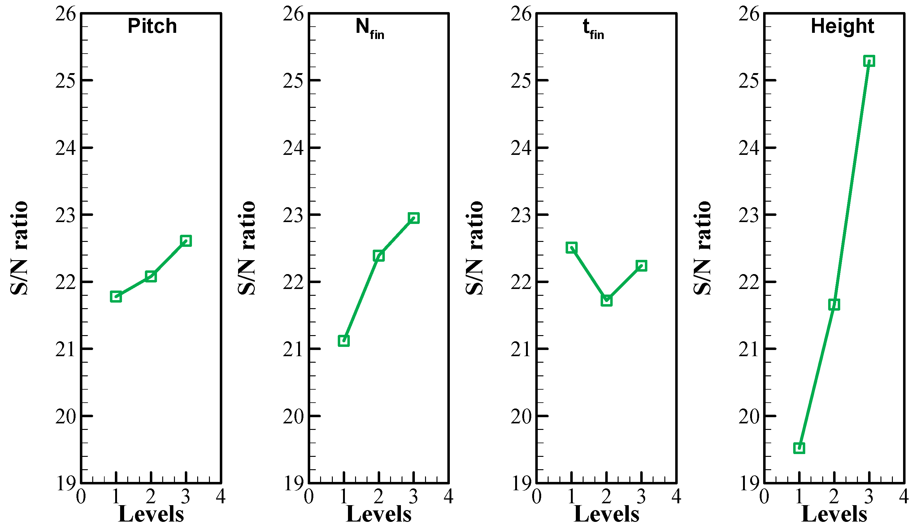
| Levels | Pitch | Nfin | tfin (mm) | Hfin (mm) |
|---|---|---|---|---|
| 1 | 21.78 | 21.12 | 22.51 | 19.52 |
| 2 | 22.08 | 22.39 | 21.72 | 21.66 |
| 3 | 22.61 | 22.95 | 22.24 | 25.29 |
| Delta | 0.84 | 1.83 | 0.79 | 5.77 |
| Rank | 3 | 2 | 4 | 1 |
| Optimum Factors | Optimum Full Melting Time | ||||
|---|---|---|---|---|---|
| Pitch | Nfin | tfin (mm) | Height (mm) | Taguchi Prediction | Tested Case |
| 3 | 5 | 0.5 | 7.5 | 21.34 | 23.82 |
Publisher’s Note: MDPI stays neutral with regard to jurisdictional claims in published maps and institutional affiliations. |
© 2021 by the authors. Licensee MDPI, Basel, Switzerland. This article is an open access article distributed under the terms and conditions of the Creative Commons Attribution (CC BY) license (http://creativecommons.org/licenses/by/4.0/).
Share and Cite
Ghalambaz, M.; Mohammed, H.I.; Mahdi, J.M.; Eisapour, A.H.; Younis, O.; Ghosh, A.; Talebizadehsardari, P.; Yaïci, W. Intensifying the Charging Response of a Phase-Change Material with Twisted Fin Arrays in a Shell-And-Tube Storage System. Energies 2021, 14, 1619. https://0-doi-org.brum.beds.ac.uk/10.3390/en14061619
Ghalambaz M, Mohammed HI, Mahdi JM, Eisapour AH, Younis O, Ghosh A, Talebizadehsardari P, Yaïci W. Intensifying the Charging Response of a Phase-Change Material with Twisted Fin Arrays in a Shell-And-Tube Storage System. Energies. 2021; 14(6):1619. https://0-doi-org.brum.beds.ac.uk/10.3390/en14061619
Chicago/Turabian StyleGhalambaz, Mohammad, Hayder I. Mohammed, Jasim M. Mahdi, Amir Hossein Eisapour, Obai Younis, Aritra Ghosh, Pouyan Talebizadehsardari, and Wahiba Yaïci. 2021. "Intensifying the Charging Response of a Phase-Change Material with Twisted Fin Arrays in a Shell-And-Tube Storage System" Energies 14, no. 6: 1619. https://0-doi-org.brum.beds.ac.uk/10.3390/en14061619