1. Introduction
An electricity distribution system, which connects a large amount of electrical equipment, is among the most complex and sophisticated platforms of energy exchange. An electricity distribution system must also continuously ensure the safety, reliability, stability, power quality, efficiency, and cost effectiveness of electrical power supply to the expectations of its users and to the requirements of governing standards, laws, and regulations [
1].
A convergence of factors, such as deregulation of electricity markets globally, the urgent need to address climate change, the achievement of maturity in modern renewable energy technologies, particularly the wind and solar generation, their low cost, etc., have led a significant shift in the source of electricity generation. This shift in electricity generation has been from bulk centralized transmission system connected power plants to more distributed decentralized distribution system connected Distributed Energy Resources (DERs) [
1,
2]. In some geographic locations, a shift in the connection of power generation to the distribution systems has been rapid. For example, in 2015, for the first time, the installed renewable energy generation capacity on the Great Britain (GB) distribution system surpassed and connected at a rate approximately 4.3 times faster than that of the installed renewable energy generation capacity on the GB transmission system [
3].
With an increase in the penetration of DERs (such as photovoltaic (PV) arrays, wind turbine generators, energy storage systems, etc.), which themselves require an increased network reliability and power quality to function properly, the already complex distribution systems have become more complex. The need, therefore, for an effective management of distribution system complexity—including the design and coordination of their protection schemes and the maintenance and improvement of electricity supply performance metrics—has never been greater [
2]. An approach to manage this growing complexity is to carefully distribute the complexity, by partitioning and or containing the growth of an existing distribution system, to smaller (but scalable), manageable subsystems called microgrids.
A microgrid, with its own group of interconnected electrical loads and DERs within a clearly defined electrical boundary, acts as a single controllable entity with respect to its connected utility system or main grid [
4]. The microgrid can operate in a grid-tied or island mode and can transition between the two modes, either seamlessly or via a power interruption, depending on the microgrid’s requirements, application, engineering, complexity, and cost dictated by the electrical loads powered by that microgrid.
“[Microgrids] are considered a critical link in the evolution from vertically integrated bulk power systems to smart decentralized networks, by facilitating the integration of DERs” [
5]. Microgrids, if properly maintained, can maintain and improve the overall electricity supply performance (such as reliability, resilience, power quality, efficiency, etc.) of distribution systems. Microgrids allow for a greater accommodation of renewable DERs, offer an increased operational flexibility to their connected main utility grid (or grids), provide ancillary services, such as a black start, peak-or retail energy time-shifting, Volt/Var support, frequency response/regulation, spinning reserve, economic or power flow optimization, etc. [
4,
5,
6,
7]. Depending on a desired use-case of a microgrid, a microgrid can incorporate several of these services.
It may be a challenge to properly design a microgrid protection scheme if the existing utility protection philosophy and practice and customer preferences do not adequately support and or address the microgrid protection needs. The added layer of complexity for microgrids, where the network conditions (such as short-circuit levels, inertia, etc.) can vary significantly depending on whether the system is grid-tied or operated in an island, makes their protection system design more challenging [
8]. Although there are DER self-protection and utility interconnection protection standards and recommendations (such as in References [
9,
10,
11]), currently, there is limited industry guidance and no presently available Institute of Electrical and Electronics Engineers (IEEE) standard for microgrid-specific protection systems.
This paper, initially, provides an overview of the impact of high penetration of DERs on the existing distribution systems. Following this, the paper discusses how microgrids can address some of these challenges, but also present their own set of protection design challenges. Furthermore, the paper reviews the current challenges with protecting microgrids and provides an overview of several commonly used protection strategies with their respective advantages and disadvantages in addressing those challenges based on the authors’ experience. Finally, the paper shares lessons learned from the authors’ own successful experiences in designing microgrid protection systems globally.
2. Microgrid Protection Challenges
Distribution systems have been traditionally designed for a one-way power flow from substations to loads. DER integration with these distribution systems presents several protection challenges [
2]. For example, utility radial systems, which were typically designed for unidirectional current flow and short-circuit sensing conditions, may require an upgrade or redesign. Relays lacking directional power flow sensing may require replacement. Relays may mis-coordinate for reverse direction short-circuits, have inadequate sensitivity to detect some short-circuits, and DER protection must coordinate with the utility auto-reclosing scheme, etc.
In addition to the challenges that independently connected DERs present to their respective utility or grid systems, microgrids, due to the nature of their operation and embedding DERs within them, present additional challenges [
8]. For example, microgrids are likely to have significantly different and variable short-circuit levels when operated in a grid-tied or island mode. They may have limited short-circuit current contribution, particularly, from predominantly inverter-based DERs (such as PV, battery-based energy storage, full-converter-based wind turbine generators, etc.). With a variation in generation, load, and circuit topology, microgrid feeders may have a bidirectional power flow. The microgrid during and after transitioning from grid-tied to island operation may lose a relatively low-impedance zero-sequence path on a normally effectively grounded distribution system. Detecting a loss of utility source could be challenging. Microgrid protection systems adapting to a circuit topology, generation, or load change should be carefully designed. Microgrid re-synchronization process with its utility grid when transitioning from an island to normal grid-tied mode, when improperly or poorly designed, may lead to problems of an excessive inrush current, disturbances in voltage and frequency, transient stability, etc.
With a change in the microgrid operating condition, including a transition to a new microgrid topology, microgrid operation in a grid-tied or island mode, etc., a microgrid protection system must ensure (for example, via adapting mechanisms, which are discussed later in the paper) the safety of the microgrid system, microgrid connected equipment, and personnel at all times. A microgrid protection system must also never falsely operate, for example, by responding to a utility or grid event that does not warrant an operation of that microgrid protection system. Additionally, during microgrid transition periods, many types of protective relays may become inoperative or enter an indeterminate state momentarily while the settings of those relays are being changed or adapted, leaving that microgrid vulnerable to a lack of adequate protection [
8].
Voltage sensing is a component of several protective elements used in microgrid systems, including Under-Voltage (UV, IEEE device 27), Over-Voltage (OV, IEEE device 59), directional Over-Current (OC, IEEE device 67), voltage-restrained OC (IEEE device 51V), and voltage-controlled OC (IEEE device 51C). These schemes are discussed in more detail in
Section 3. Consequently, loss of a voltage input to a relay, caused for example by a blown voltage transformer (VT) fuse, can have a significant impact on microgrid protection schemes. Voltage-restrained or voltage-controlled OC elements could operate inadvertently on a blown fuse condition on a set of VTs [
12]. UV elements could also operate inadvertently on a blown fuse condition on a set of VTs [
13]. If a voltage sensing function is not available, directional OC elements may mis-operate or not operate when needed [
13]. These and other anticipated impacts of loss of a voltage input to microgrid protection schemes must be considered. Protection schemes that do not require voltage sensing for protection (such as current differential and non-directional OC protection) are not direct replacements for voltage controlled and voltage restrained OC protection schemes [
13]. The differential current scheme requires measurement inputs from remote terminals of the protected circuit elements, and the non-directional OC lacks the sensitivity of the directional OC and voltage controlled and voltage restrained OC schemes.
Microgrids can have a considerable portion of their generation sourced from inverter based DERs. A DER’s short-circuit contribution is dictated by its type, design, and controls. Inverter-based DER controls are typically designed or set to limit the maximum output current to 1–2 p.u. (but more often around 1.1–1.2 p.u.) of the rated current of those DERs [
14,
15,
16]. Traditional power system equipment (such as synchronous or asynchronous machines) could contribute short-circuit current up to 5–8 p.u. of the machines’ rated current [
14,
15,
16]. Furthermore, inverter-based DERs not only have a lower positive sequence short-circuit contribution to system short-circuits, but, during unbalanced system conditions, those DERs may not produce any negative-or zero-sequence current [
8,
17]. Therefore, detecting short-circuits (particularly, asymmetrical short-circuits) and identifying short-circuit current directionality in a microgrid, particularly when operated in an island mode, adds to the protection system design challenge [
8].
Most microgrids have shorter feeder-circuit lengths. They can also have lower short-circuit levels and higher short-circuit source impedances; this is particularly the case when microgrids are operated in an island mode. These conditions lead to an increased sensitivity of microgrid voltages to electrical disturbances (such as short-circuits, generation or load-step changes, etc.) within those microgrids, and DERs’ controlled voltages will likely be impressed on to the connected electrical load’s terminals [
5]. Additionally, as low-inertia inverter-based DERs are a predominant source of electricity in microgrids, particularly when in island mode, the microgrids generally have low inertia [
5,
8]. This reduction in inertia leads to an increased sensitivity of system frequency to electrical disturbances, including a rapid drop in system frequency during short-circuits, a sudden loss of a large generator, or a sudden pickup of a large load. To maintain electrical stability, reliability, and power quality of a microgrid during these conditions, rapid detection, communication, and clearance of short-circuits is, therefore, essential [
5,
8].
3. Microgrid Protection Strategies
There are many approaches to microgrid protection, and each strategy has its advantages and disadvantages that depend on a combination of factors. These factors include the DER types used in a microgrid, microgrid circuit topology, a customer’s performance and service requirements (i.e., reliability, and power quality), utility practices (internal and external to a microgrid), and the cost associated with implementing and operating microgrid protection strategies.
Novel microgrid protection approaches exist and are detailed in the available literature [
18,
19,
20,
21]: to a name a few, advanced optimization for relay setting calculation [
22,
23], application of machine-learning algorithms in adaptive protection [
24,
25], and distance protection on distribution voltage level [
26,
27]. However, many of these listed approaches are in the research or prototype phase and have not been widely implemented in the real-world microgrids. In this paper, the performance of commonly used and field-tested protection strategies, in terms of the performance criteria of selectivity, speed, sensitivity, reliability, and cost, in the real-world microgrids are discussed based on the authors’ experience.
A microgrid protection system design involves a consideration of various performance criteria and an appropriate set of compromises based on the microgrid’s application. Furthermore, backup protection and redundant communication schemes are typically required to ensure adequate overall protection system reliability. Even though it may be acceptable for backup protection to have compromised selectivity and, thus overtrip, the backup protection must still provide adequate protection in cases of primary protection failure.
In microgrid applications, there are additional technical criteria compared with traditional distribution systems without DERs. One such criteria is system stability, which requires that the short-circuits are cleared rapidly, such that the synchronous generators that are connected to and within a microgrid can recover to a stable operating condition and do not cause power quality issues. For example, differential and or communication-based protection schemes can be utilized when traditional time-graded OC protection schemes do not provide sufficiently fast response. While a sufficiently fast response is required to maintain system stability and required power quality, it is also advantageous to ride-through short-circuits as appropriate to avoid unnecessary outages while in an island mode. Of course, a microgrid’s fault ride-through during an electrical disturbance must consider the stability and power quality performance tolerances of connected equipment and the set design tolerances of that microgrid. There may also be ride-through requirements from the utility on the microgrid when it is operated in a grid-tied mode, for example, as part of the utility’s adoption of the IEEE Standard (Std) 1547: 2018 [
9], which needs to be considered as part of the microgrid’s protection design.
Meeting various protection criteria at once in a microgrid application can be challenging. In the authors’ experience, the complexity of the protection system is an important consideration, as it may adversely impact the overall microgrid system’s reliability and cost, particularly when additional personnel training, required documentation, testing, and commissioning are accounted for. Therefore, tradeoffs that allow for a simpler microgrid protection system, while meeting and maintaining the safety, technical, functional, and cost requirements of a microgrid, are preferred.
Within a microgrid, both system and equipment level protection systems must be coordinated, and such coordination is unique to a system under consideration. This paper, however, primarily focuses on microgrid system protection.
3.1. Differential Protection Scheme
Current differential protection schemes, due to their advantages of their operational speed, sensitivity, and reliability, are extensively used in substation and transmission protection schemes. Since such schemes are not affected by a bi-directional power flow, varying and or low short-circuit current levels, meshed configuration, and weak short-circuit infeed, they offer several benefits and are advantageous for use in microgrids [
8,
28]. Because of the aforementioned advantages of this protection scheme, the scheme can be successfully applied in both microgrid grid-tied and island modes.
To achieve the required protection performance with the differential current scheme, typically, both phase and sequence currents are used. Phase differential elements of the scheme are responsible for providing high speed protection for short-circuits that have high short-circuit currents, while the scheme’s negative-and zero-sequence differential elements provide a more sensitive protection for low short-circuit-current-based unbalanced short-circuits [
29].
When using this scheme, there is a trade-off between protection sensitivity (including restraint functions) and security performance: An increased protection sensitivity may come at a cost of reduced protection security, leading to spurious or nuisance trips due to short-circuits outside the implemented scheme’s zone of protection. Therefore, care must be applied when setting a differential relay pickup threshold, which neither should be a very high value, allowing it to detect short-circuits within its zone of protection, nor it should be a very low value that the relay responds to, for example, a current transformer (CT) saturation, line charging effect with that zone of protection, etc. Most modern microprocessor-based relays, however, use CT saturation detectors and line charging current compensation to overcome these inaccuracies [
30].
A salient feature of current differential schemes is that they do not require voltage sensing. To increase the overall reliability of a protection system, particularly when differential protection elements are selected as the primary protection, OC-and UV-based protection elements could be used as a backup protection.
Implementing a differential protection scheme requires additional CTs, relays, and communication infrastructure; this may affect the overall cost of a microgrid [
31]. Moreover, differential protection can be technically difficult to operate or may be impractical for protection of some power system components, such as distribution lines with a radial topology.
Based on the authors’ experience with implementing differential protection scheme in microgrid projects, this scheme provides the required speed and reliability performance as part of a bus, transformer, or generator protection, if the project can accommodate the cost and the scheme is technically practical for the microgrid topology.
3.2. Voltage-Controlled and Voltage-Restrained Over-Current Protection Scheme
When a microgrid is connected to a weak external grid or when operated as an island, where the source of short-circuit current within that microgrid may be small, the OC-based protection alone may not adequately discriminate a short-circuit current from a normal high current or temporary current overload. However, as the source impedance is typically high in such microgrid operating conditions, the microgrid voltages may drop significantly for short-circuits with low short-circuit-to-ground impedances. This drop in microgrid voltages, in combination with an OC protection scheme, can be used to detect short-circuits more sensitively. A protection scheme that works on this well-known principle is called voltage-controlled and voltage-restrained OC protection scheme [
29].
However, when operating in a microgrid’s island mode, adequate protection coordination and selectivity, and identifying a short-circuit and its location, can be a challenge due to the following reasons [
8]: (a) the need for using low current pickup relay settings to allow a pickup of low short-circuit currents; (b) during short-circuits, similar voltage-drops are impressed across a large part of that microgrid when islanded or when connected to a weak utility system or grid; and (c) transient conditions, such as a transformer inrush, that may produce a voltage drop similar to a short-circuit condition.
Since implementing the voltage-based OC protection requires VTs, in addition to the required CTs and relays, implementing the scheme affects the overall cost of a microgrid [
31].
Based on authors’ experience with the implementation of voltage-controlled and voltage-restrained OC protection in microgrids, these schemes can provide the required sensitivity in island operation. The authors of this paper frequently apply these techniques as a component of successful and operational microgrid protection applications.
3.3. Adaptive Protection Scheme
Adaptive protection refers to a scheme where a protection system, in a timely manner, adapts to a change in a system operating condition [
8]; for example, a protection system adaption could include a change in relay group settings or setting values, protection functions, and or control logic. In a microgrid, varying system conditions, such as an operation in a grid-tied or island mode or a change in microgrid topology, are the principal reasons for using this scheme [
32].
There are two adaptive protection-scheme approaches: (a) event-table-based and (b) near-real-time-calculation-based. Each approach has its advantages and disadvantages, and they must be thoroughly evaluated to ensure suitability of selected approach’s impact on safety, protection performance (i.e., selectivity, speed of operation, reliability, dependability, and security), required communication infrastructure, complexity, engineering, customer or utility practices or grid requirements, and cost.
In an event-table-based approach, at the microgrid protection system design stage, all possible microgrid operating conditions are thoroughly thought through and a set of protection settings and control logic is developed for each protective device and microgrid operating condition. Based on this, a look-up event table, listed with a mapped set of microgrid operating conditions against their corresponding pre-calculated protection settings groups, is prepared. When a planned microgrid operating condition is identified, the pre-calculated protection settings group corresponding to that identified operating condition for each device is fetched from the event table and is applied in that protective device in a timely manner.
In a near-real-time-calculation-based approach, an accurate model of the microgrid system is developed and real-time measurements from the microgrid site are fed into the model as an input. A set of power system analysis software and hardware tools is used to—rapidly but accurately—simulate the microgrid system condition, analyze the simulated outputs, and calculate the required per protective device protection settings group. The calculated protection settings groups are then applied in corresponding microgrid protective device hardware in a near-real-time manner via a fast communication infrastructure [
8].
An important consideration in the design and operation of an adaptive protection scheme is the determination of the exact conditions and, perhaps, the instance of time the change in the protection settings must occur upon detection of a microgrid’s transition to a planned operating condition, for example, a microgrid’s transition from a grid-tied to an island mode. This is important because many types of protective relays may become inoperative or enter an indeterminate state momentarily while their settings are being changed, leaving a microgrid vulnerable to a lack of protection during a protective relay settings update or change event [
8].
The authors of this paper frequently and successfully applied adaptive protection schemes in currently operating microgrids. Aspects of an adaptive protection scheme that was successfully applied by the authors of this paper in several microgrid projects is detailed in
Section 4.2.
3.4. Communication-Based Protection Scheme
There are several advantages of using communication-based protection schemes in microgrid applications due to their immunity to external loading conditions, high-impedance short-circuits, bi-directional power flow, modes of operation, and looped configurations [
33,
34,
35]. In these schemes, a set of permissive and blocking signals are exchanged between the relays based on a set of gathered information, such as voltage and current magnitudes, sequence quantities, phase angles, and direction for current measurements. These signals are then used by the relays to locate and or to clear a fault. Thus, reliable and high-speed communication channels, such as fiber-optic-or Ethernet-based systems, are required for these protection schemes to perform at an acceptable level using peer-to-peer communication or network protocols, such as International Electrotechnical Commission (IEC) Std 61850-8-1: 2020 [
36] Generic Object-Oriented Substation Event (GOOSE) messaging. GOOSE messaging can offer communication latency of under 4 ms, which is adequate for protection and control. As the setup of a fast, broadband-based communication infrastructure—an indispensable aspect for current and future smart grids—becomes common, the same infrastructure could then be used for protection (if the infrastructure has a satisfactory reliability and speed performance), driving down the cost of implementing such a protection scheme [
33].
Communication-based protection schemes are typically used as part of the primary protection, and they include a variety of schemes, such as directional interlocking, Direct Transfer Trip (DTT), Permissive Overreaching Transfer Tripping (POTT), and Directional Comparison Blocking (DCB). To allow for microgrid protection during a communication failure, a slower backup non-communications-based protection scheme is required and typically implemented; such backup schemes, for example, could include time-graded OC elements with voltage and or directional control supervision.
Interlocking schemes have been used extensively in the industry for radial distribution systems. When these schemes incorporate a directional element, in addition to the use of a current magnitude, they are more suitable for microgrid applications [
8]. DTT schemes, which use permissive signals, have many uses in microgrid and DER applications, including preventing unintentional islanding, reacting to breaker failure events, etc.
Directional OC control is often used by communication-based protection schemes to check whether the fault is located in front of or behind the measurement point [
37]. There are challenges to implementing directional controls in a microgrid, particularly, accommodating the microgrid’s various operational modes. For example, different impedances of microgrid fault current sources can challenge directional polarization [
38]. Furthermore, changes in system frequency during a fault can also challenge directional polarization [
39]. Phase, negative-sequence, zero-sequence, and voltage memory are used as polarizing quantities by different devices and in different applications [
37]. Different polarization methods may be available, and the performance of the polarization method selected must be considered. It is useful to test the directional OC settings using a short-circuit model for faults at different microgrid locations and configurations.
Based on authors’ experience with the implementation of communication-based protection schemes in microgrid projects, these schemes can provide the required speed and reliability for bus, line, anti-islanding, and other microgrid protection functions. Consequently, the authors of this paper frequently apply communication-based schemes as a component of successful and operational microgrid protection systems.
3.5. Under/Over Voltage and Under/Over Frequency Protection Schemes
UV, OV, Under-Frequency (UF, IEEE device 81U), and Over-Frequency (OF, IEEE device 81O) are among the most commonly used protection schemes implemented at both an equipment level (via self-protection internal logic of that equipment) and at a microgrid system level (via protection relays). Most DERs have these protective functions integrated into their controls and are usually enabled by default. These integrated protection elements could be used to protect a DER from damage due to abnormal power system conditions, disconnect or isolate that DER from the questionable power system during short-circuit or unplanned or unintentional island conditions, and more. However, there may be other DER specific protection systems, such as direct current (DC) OV and UV protection schemes on inverters, battery overcharge protection on Battery Energy Storage Systems (BESSs), mechanical, over-or under-speed protection schemes on synchronous or asynchronous generators, etc., that may complement the DERs’ UV, OV, UF, and OF protection schemes.
A fundamental tradeoff when selecting a set of DER voltage and frequency protection settings is the balance between the need to trip-to-cease-to-energizing short-circuits (or unintentional islands) and the need to ride through short-circuits and support the connected system while the fault is cleared by some other device. In microgrids, especially when operating in an island mode, DERs are among the principal sources of power supply. Consequently, it is essential that when the system is in an island, the DERs can ride-through system voltage and frequency variations that are typical of a low-inertia system. While a microgrid is in an island mode or state, system voltage and frequency can vary significantly as compared to nominal operating conditions and more frequently than when that same microgrid is in a grid-tied mode. The IEEE Std 1547: 2018 recognizes this need for different DER settings while operating in an island mode [
9]. However, this need for ride-through while a microgrid is in an island mode must be balanced with the utility system operation and protection needs while the DER is in a grid-tied mode. Once adequate UV, OV, UF, and OF protection settings have been determined for the individual DERs, backup UV, OV, UF, and OF protection settings for protective relays can be chosen to respond before or after the individual DERs, as desired for the application.
At a microgrid system level, the UV, OV, UF, and OF protection schemes are sometimes used exclusively for system protection. This is mostly used in applications where microgrids are small and or simple. A few of these protective functions, as discussed in
Section 3.2, are often used to support other implemented protection schemes to improve the overall protection system’s sensitivity and reliability. Voltage-and frequency-based protective elements on their own have significant limitations for microgrid protection applications. These parameters can indicate a presence of an electrical disturbance (such as a short-circuit, sudden connection or loss of generation or load, transformer energization, etc.). However, these elements have both reliability and selectivity limitations. For example, an under voltage can be indicative of either a large load acceptance, inrush condition, or short-circuit condition, and it may require significant delays to prevent nuisance operations. Furthermore, voltage-and frequency-based protective elements are inherently non-selective. That is, the location of the short-circuit cannot be readily determined from a grid side fault to inside the microgrid fault. This lack of selectivity can cause an outage of more high priority loads than necessary and can challenge locating a short-circuit. In large systems, such as distribution system microgrids, with long circuits, including underground circuits, locating a short-circuit even with selective protection can be challenging, which could delay the eventual restoration of these priority loads. In the US, the article 700.10(B)(5)(b)(ii) of the 2020 National Electrical Code (NEC), National Fire Protection Association (NFPA) 70 in [
40], requires protection coordination in emergency systems with a common OC protective device, indicating the value and need for selective coordination, even in contingency operations, where loads are a high priority or critical.
3.6. Performance Comparison of Protection Schemes
The advantages and disadvantages associated with commonly used microgrid protection strategies were discussed in the previous subsections. The performance in terms of selectivity, speed, sensitivity, reliability, and cost, for each of the discussed microgrid system protection strategies is summarized in
Table 1 based on authors’ experience in implementing them as part of successful operational microgrid protection systems. Please note that the advantages and disadvantages detailed in
Table 1 should be read in the context of the discussion presented in this paper.
As can be seen from
Table 1, not every protection scheme is suitable for every microgrid protection system, but a trade-off among the protection schemes exists. These trade-offs must be carefully studied and optimized in meeting both mandatory and non-mandatory but desirable requirements of a microgrid protect system and project. Furthermore, protection schemes can be used in combination to achieve improved performance.
4. Practical Experiences with Microgrid Protection Schemes
Principal microgrid protection system design challenges and a few approaches to addressing them, based on authors’ experience in developing microgrids globally, are discussed in the subsequent subsections.
4.1. Utility Protection Practices and Standards versus Microgrid Protection Needs
Microgrid protection often requires a different approach to system and equipment protection than a conventional distribution system protection does, especially, to accommodate the microgrid grid-tied and island modes of operation. Integration of microgrid and utility system protection systems may present several technical challenges. In a microgrid that is privately owned and operated, say, by a utility, it is often preferred by the utility to base the microgrid protection philosophy on the existing internal standards and practices of that utility. However, typical utility protection philosophy may not properly address the unique protection needs of microgrids. It becomes a challenge to adapt typical distribution protection template relay settings for microgrid protection. In the authors’ experience, significant differences between microgrid protection needs and existing distribution protection standards have come from protection speed requirements, short-circuit current directionality and ground short-circuit protection, and the use of DTT and anti-islanding protection; these needs are discussed below.
Microgrid protection often requires a significantly faster operation than a traditional distribution system requires, especially when the microgrid is operating as an island. The protection speed requirements are discussed in References [
5,
8]. For example, the use of traditional time-graded OC protection is a common distribution system protection technique. This approach relies on delaying farther upstream protection to achieve selective coordination, often using coordination time intervals of several hundred milliseconds and the interrupting devices must be implemented radially with non-directional power flows typical of a centralized power system. Differential relaying and communication-based schemes, described in
Section 3.1 and
Section 3.4, respectively, can operate faster to meet microgrid protection and stability needs, while also better maintaining protection zone selectivity than time-graded OC protection schemes. Time-graded OC is often used in backup microgrid protection schemes, acknowledging that the delays with the backup protection operation may result in a reduction of selectivity, stability, and or power quality.
Next, integration of DERs can introduce a bi-directional short-circuit current in a system that has been historically radial and with non-directional protection schemes. The bi-directional short-circuit current can introduce many challenges [
2]. In microgrids, these challenges are often exacerbated by the use of grounding transformers, which can be required by utility standards, for maintaining effective grounding while the microgrid is islanded, reducing the over-voltages on un-faulted phases if a DER contributes to supply power to a short-circuit after the distribution system was disconnected from the grid, and for other reasons.
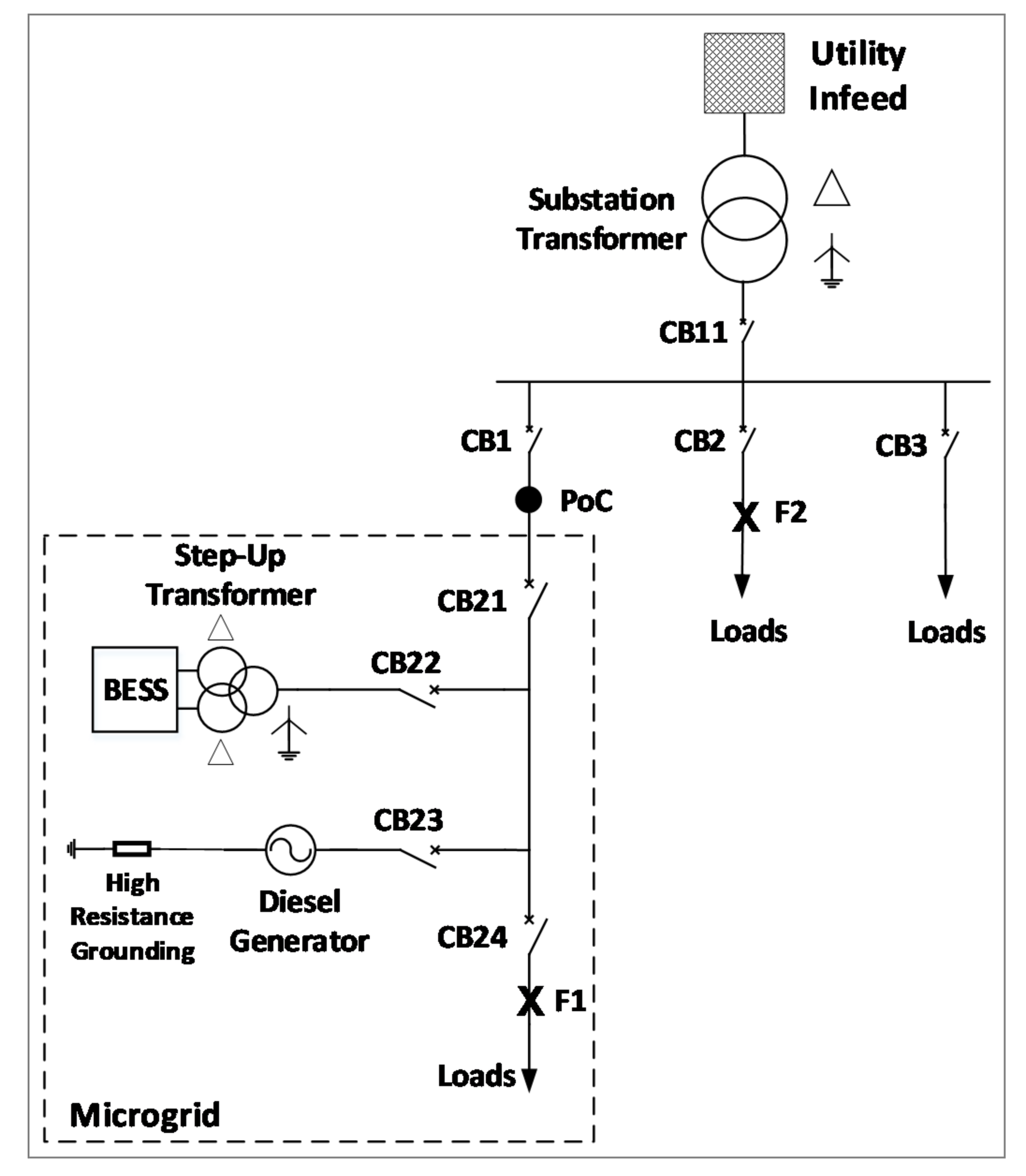
Two examples of significant impacts are as follows: (a) de-sensitization of existing system protection and (b) reverse short-circuit current flow for out-of-zone short-circuits. These impacts are illustrated using an example microgrid system in
Figure 1 and relevant description below.
In
Figure 1, a utility integrated microgrid serves critical loads on the feeder downstream of CB1; the microgrid is the network enclosed in the dashed-line envelope. The microgrid’s Point of Connection (PoC) is at the microgrid’s connection side of the breaker CB1. All the circuit breakers (CBs) in
Figure 1, except CB23, are operated as normally closed during the utility’s normal operation and the microgrid’s normal grid-tied operation. Under this condition, if we consider a short-circuit at the location F1 (in
Figure 1), the short-circuit current flow through the breaker CB21 will consist of short-circuit current contribution from the utility alone and the breaker CB24 will consist of a combined short-circuit current contribution from the utility and the microgrid’s (connected and online) BESS units. Therefore, under this considered microgrid (grid-tied) operating and short-circuit condition, the breaker CB21 may see less short-circuit current flow through it than if the microgrid DERs were disconnected and offline. This difference in the short-circuit current can be significant when ensuring that the end-of-the-line short-circuits are detected—sensitive protection for end-of-the-line short-circuits may require using a different relay (in this case, CB24) to mitigate the impacts of de-sensitization during the considered short-circuit at the location F1. For a short-circuit at location F2, however, for the same utility and microgrid (grid-tied) operating condition, the breaker CB1 may see short-circuit current flow towards the substation bus, but the breaker (CB1) must not operate. These effects can be especially pronounced for sensitive earth short-circuit protection and systems where instantaneous protection (e.g., a fuse-saving scheme), among others, is used.
DTT and anti-islanding protections are often required when integrating a DER. These protection functions can be used to trip DERs offline in certain conditions. Ensuring DERs are disconnected from system short-circuits and unintentional islands is imperative to clear short-circuits and to maintain a safe system operation. However, tripping DERs offline during system events can be undesirable in microgrid applications, as offline DERs will be unable to seamlessly island and energize or supply critical microgrid loads. These opposing objectives must be carefully balanced during the microgrid protection design stage. For example, depending on short-circuit location, operational conditions, and other factors, microgrid trip signals can be routed to trip the microgrid-utility interconnection breaker instead of the microgrid embedded DERs. Care must be applied when automatically re-energizing DERs to ensure that a short-circuit is not re-energized or unintentional island is produced.
Regardless of a protection approach selected for a microgrid, there is complexity involved in implementing and testing the designed protection schemes. A carefully, well designed microgrid protection system can not only meet the speed of operation requirements, but it can also (adequately) achieve the selectivity and reliability requirements.
4.2. Approach to Switching between Protection Setting Groups with Automatic Correction
Understanding the microgrid operating conditions (such as grid-tied mode, island mode, and sub-operational modes, such as a change in the microgrid’s topological configuration or availability of generation sources) that lead to a significant variation in short-circuit levels within that microgrid is an essential component to determining the required protection relay settings that are each specific to those operating conditions. Moreover, microgrid protection settings often vastly vary among microgrid operating conditions.
The authors of this paper have successfully implemented several microgrid protection systems using the adaptive protection scheme described in
Section 3.3 combined with other complementary strategies described in
Section 3. An adaptive protection scheme refers to modifying a set of relay protection settings that are appropriate for an identified, planned system operating condition. Many microprocessor-based relays allow for incorporation of multiple relay settings, referred to as protection settings groups or profiles; however, one setting group or profile is active in that relay at any given time. In typical distribution system protection applications, a protection settings group uses a set of pre-calculated settings for a specific application and or a system operating condition, such as for a normal operating condition, abnormal operating condition (for example, a system overload), contingency (for example, an outage due to a storm event), etc. In a microgrid, typically, each principal protective device uses a minimum of two protection settings groups: one group for the microgrid’s grid-tied mode operation, and another group for the microgrid island mode operation.
To ensure that the correct protection settings group for the system operating condition is applied to a microgrid protective device, the protective device will require information about the microgrid’s state, including its interconnection with the utility system or grid via the interconnection breaker status. Many microgrid protection schemes use one or more of the following aspects to apply an appropriate protection settings group: physical-contact status inputs, communication-based inputs from Supervisory Control and Data Acquisition (SCADA), and communication-based inputs from other protective devices and or controllers (e.g., via the IEC Std 61850-8-1: 2020 GOOSE messaging or hardwired connections).
A principal challenge of an adaptive protection scheme is that a protective device, such as a relay, may enter an indeterminate state while switching between the protection settings groups. This may leave a microgrid relay’s zone of protection temporarily unprotected. Switching between protection settings groups must therefore be carefully choreographed and timed to ensure that the microgrid system is protected during its transitional states, for example, when the microgrid is transitioning from its grid-tied to island mode. A number of techniques could be employed here including the use of early and fast position status switches and overlapping protection schemes.
Transitioning between the protection settings groups during the microgrid open transitions (i.e., transitions that include the time when the microgrid system is de-energized) are more straightforward. In these applications, the protective devices can switch between the protection settings groups when the microgrid is de-energized, prior to re-connecting the microgrid to the grid or energizing the microgrid island via the DERs connected to that microgrid.
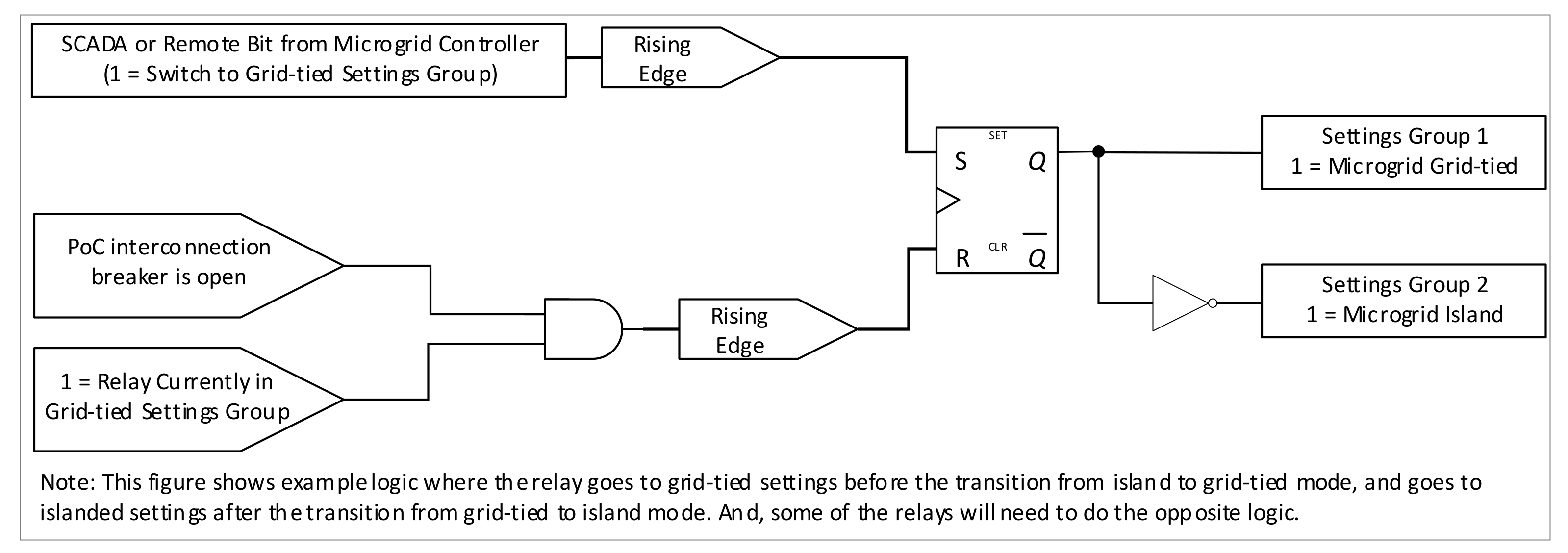
During a microgrid’s seamless transition between its operating modes, for example from a grid-tied to island mode, the relay protection settings group must be switched while the microgrid is still energized and operational. To address this challenge, an author of this paper, collaborating with others, developed a patented Microgrid Adaptive Relaying method to switch between settings groups [
41]. This method allows for switching of a relay protection settings group during a microgrid’s seamless transition during transitional states, ensuring the system is protected throughout the transitions. For example, when switching from a grid-tied to an island mode, an implementation could be as follows: (a) a SCADA command signal is sent a few seconds prior to the opening of microgrid interconnection breaker at the PoC to some of the microgrid protective devices to change their protection settings groups, such that the change in protection settings groups in those devices occurs before opening of the microgrid interconnection breaker; and, (b) shortly after the microgrid interconnection breaker opens and the microgrid has islanded, the remainder of the microgrid protective devices change their protection settings groups.
The microgrid protection devices are carefully grouped between the devices that require their protection settings groups changed before and after each microgrid transition. This to ensure that the microgrid is protected for electrical disturbances (such as short-circuits) before, after, and during the seamless transition between microgrid operating modes. This approach comprehensively protects the microgrid system, while compromising only protection selectivity during the transition.
Figure 2 shows the basic logic behind this method, which was successfully deployed and tested by the paper’s authors on several microgrid systems that are currently in operation.
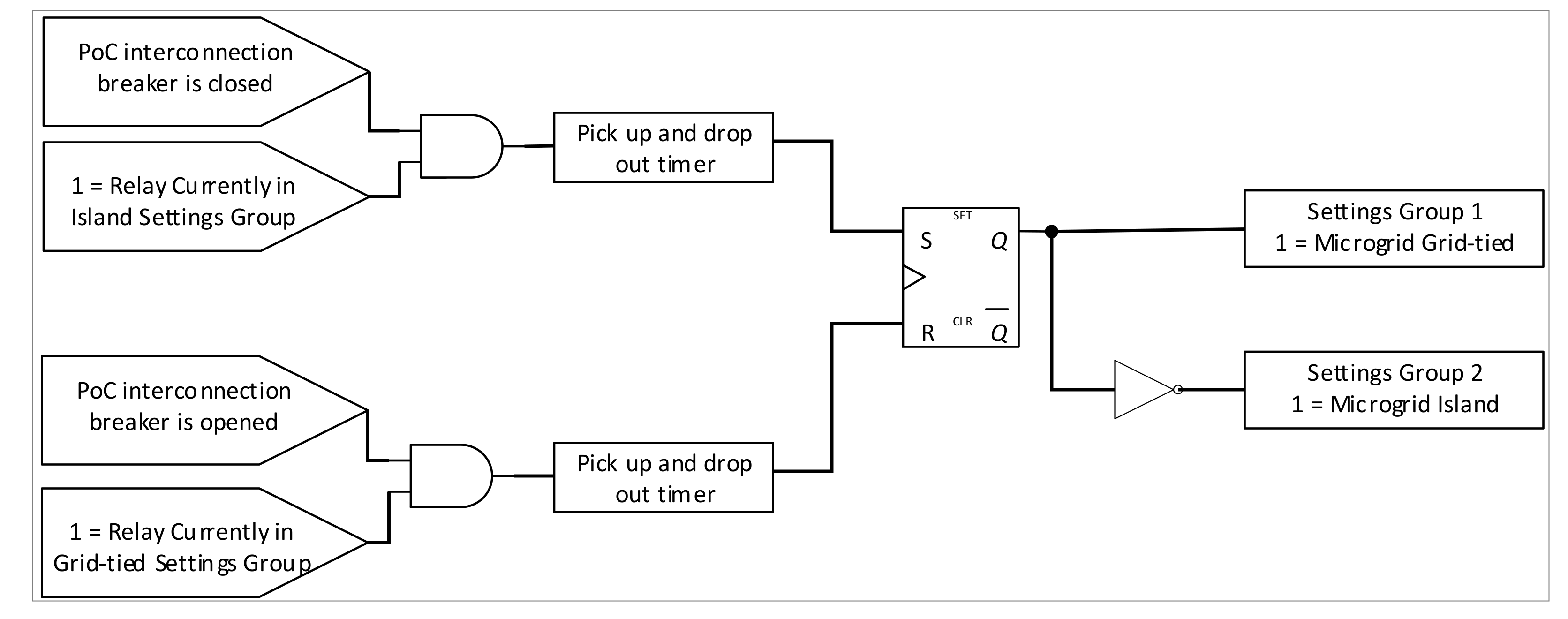
When implementing a microgrid protection scheme with multiple settings groups per relay, it is necessary to ensure that the relays are set with the correct protection setting groups at all times. For instance, during a microgrid’s transition from an island to grid-tied mode, if a protective device, which was selected to have its protection settings group changed prior to that transition, but changed after that transition, there is a possibility that the protection device may mis-operate or fail to operate as desired. This is an important challenge to address to ensure the microgrid system is protected as intended.
To address this challenge, an author of this paper, collaborating with others, developed a patented Control System Countermeasures (CSC) method [
42]. This method uses programmable logic customization features of the microprocessor-based relays. The logic design allows a relay to confirm that it has the correct protection settings group appropriate to the microgrid operating condition per the adaptive protection scheme. Using a relay’s internal logic and inputs from other electronic devices and or relays, each relay can verify whether the active protection settings group currently deployed matches or are appropriate for the present state and topology of the microgrid system. With this information, the microgrid controller and a microprocessor relay can use the designed countermeasures to initiate a settings group change to correct discrepancies between the active settings groups and microgrid operating states, ensuring the protection and security of the protected system by that relay.
This scheme can accommodate short-term mismatches between the system configuration and protection settings groups in preparation for a microgrid transition, for example, between the grid-tied and island mode, or vice versa. However, if the mismatches are found to persist, they can be detected and corrected accordingly.
Figure 3 illustrates the basic logic for implementing this method. There may be additional factors that affect the final design implementing the method. For example, the complexity of the microgrid where this method is implemented, control signals to be used for system configuration, and communication link status overseeing the status bits are factors to list a few.
4.3. Seamless Microgrid Transition between Grid-Tied and Island Modes
Authors’ field experience on two separate example microgrid design projects are detailed below.
4.3.1. Example Microgrid Experience #1
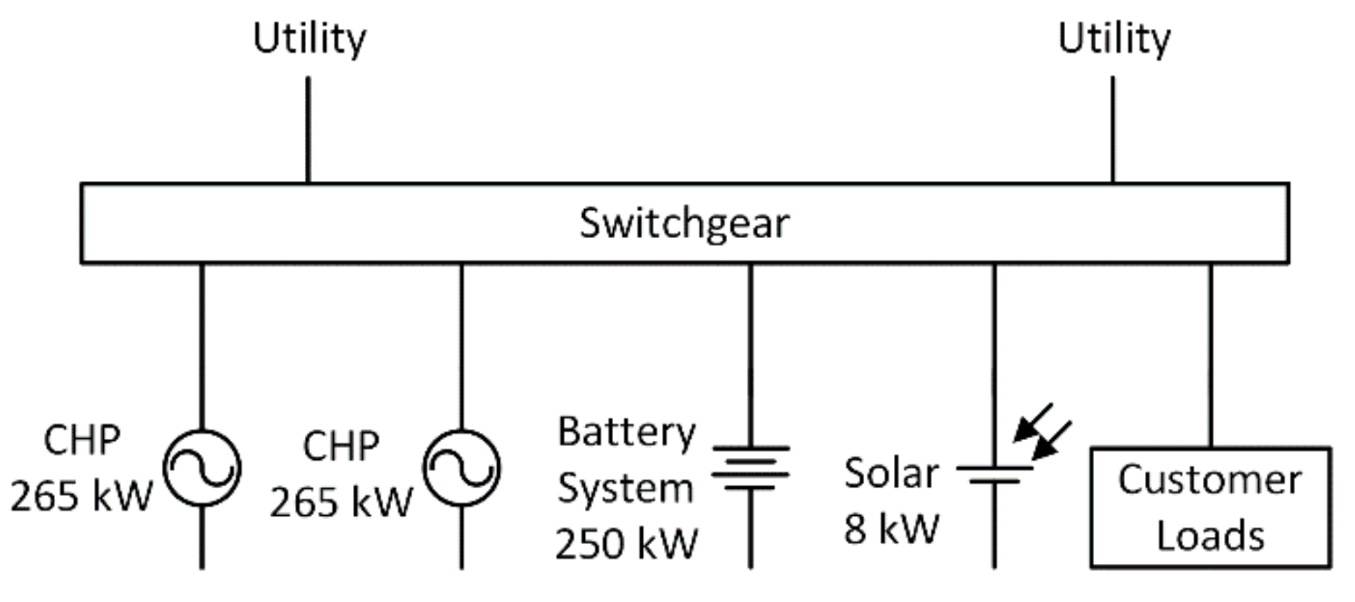
The authors of this paper recently designed and commissioned a microgrid system, detailed in Reference [
43], with a high-level single-line diagram shown in
Figure 4. A principal feature of this microgrid was that it can seamlessly transition between the grid-tied and island modes, both during planned and unplanned system events. Thus, avoiding a momentary outage to connected customers within that microgrid. This system’s microgrid controller, considering various decision-making criteria, evaluates the system conditions to control the microgrid’s relay protection behavior by enabling or disabling the seamless unplanned transfer protection tripping functions.
If the system is capable of seamless unplanned transfer to islanded operation, the microgrid controller enables the relays’ seamless unplanned transfer protection functions. This causes the microgrid protection system to trip the interconnection breaker at the PoC during external system disturbances. The microgrid relays use a combination of DTT signals, directional OC, OV, UV, UF, OF, and Rate of Change of Frequency (RoCoF) protection functions, allowing the relays to securely, sensitively, and rapidly detect external system short-circuits and Loss of Mains (LoM), triggering a trip of the inter-connection breaker at the PoC and the microgrid transitioning to an island.
In a situation where the online DERs cannot supply the microgrid loads, the microgrid controller will disable the relays’ seamless unplanned transfer protection functions, leaving the microgrid PoC interconnection breaker closed throughout the external system events (e.g., faults). This allows the microgrid connected loads and DERs to rely on their own protection and the external system’s protection. If the DERs trip based on their protection settings, it prevents the DERs’ contributions to system short-circuits. This also allows the microgrid loads to remain connected to the utility system, allowing the utility protection systems to clear the short-circuit (and reclose after a temporary short-circuit), and rapidly restore the power to the microgrid connected loads.
System studies at the design phase were crucial in evaluating whether the DERs and the microgrid would ride-through unplanned outage events. For example, studies showed that, for a successful seamless islanding transition during an unplanned external event, the criteria included the following: both Combined Heat and Power (CHP) generators are running, the maximum net power import across the interconnection breaker is within acceptable limits, the load was less than the combined capacity of the DERs that are online, and DERs were expected to ride through the event. Furthermore, the microgrid’s system inertia was relatively low, necessitating a faster system protection response to achieve seamless transitions during unplanned events and a precise control to minimize the system voltage and frequency variations during seamless planned transitions.
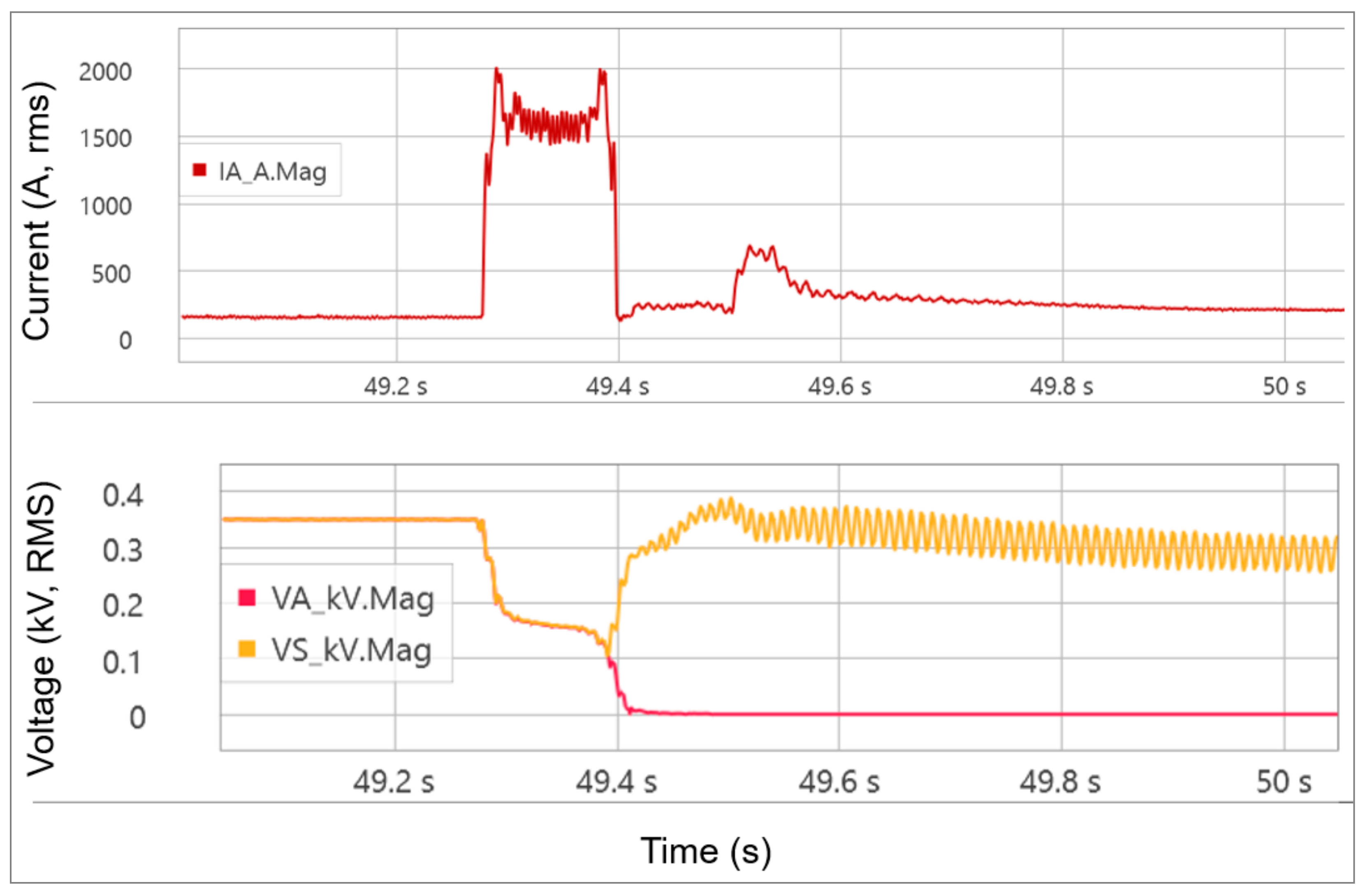
The microgrid’s ability to seamlessly transition during unplanned events was tested during operation. For example, during a real utility event, the microgrid successfully detected the event and seamlessly transitioned from grid-tied to island mode. During this event, a fault occurred on the sub-transmission circuit supplying the microgrid. The microgrid DERs supplied the fault current, which was detected promptly by the UV-supervised directional OC protection at the interconnection circuit breaker relay.
Figure 5 shows the microgrid interconnection circuit breaker relay current and voltage measurements before the fault, during the system fault, and after the microgrid has separated from the distribution system. The microgrid voltage is depressed during the fault, but the microgrid voltage recovers while the utility distribution system voltage collapses due to tripping of the transmission system protection after the microgrid separated from the distribution system.
The microgrid system detailed in this subsection also used the CSC method described in
Section 4.2. to ensure the relays maintained correct protection settings groups.
4.3.2. Example Microgrid Experience #2
When designing a microgrid protection system, identifying when to separate from the utility system to initiate an island operation is an important decision. There are several competing factors and trade-offs to be accounted for and balance:
Utility system protection speed requirements: The faster system faults or disturbances in the utility are isolated, the better.
Equipment ride-through capabilities: The more that the connected equipment can tolerate disturbances that are longer, more severe, and of various types, the better.
Microgrid system’s quality of supply performance requirements.
Protection sensitivity leading to switching between microgrid modes (e.g., grid-tied and island): The microgrid’s protection system should be sensitive to external disturbances and allow the microgrid to switch to an appropriate mode, as needed, to reduce the impact of utility disturbances on sensitive equipment connected to that microgrid. However, the same protection system should not be too sensitive that it leads to a nuisance, frequent switching between microgrid modes.
Provision of support to the utility system: The microgrid equipment, particularly DERs, may have to remain connected to the utility via the microgrid for as long as possible and support the grid system voltage and frequency during utility system disturbances.
Some of these considerations drive the microgrid to disconnect more quickly, while others drive the microgrid to remain connected to the utility system longer. Several of these factors were at play when the authors designed the protection system for a real-world microgrid described in
Section 4.1. This microgrid required a seamless transfer between its grid-tied and island modes. A few field experiences drawn from this work are discussed in this section.
The utility-microgrid project, as shown in
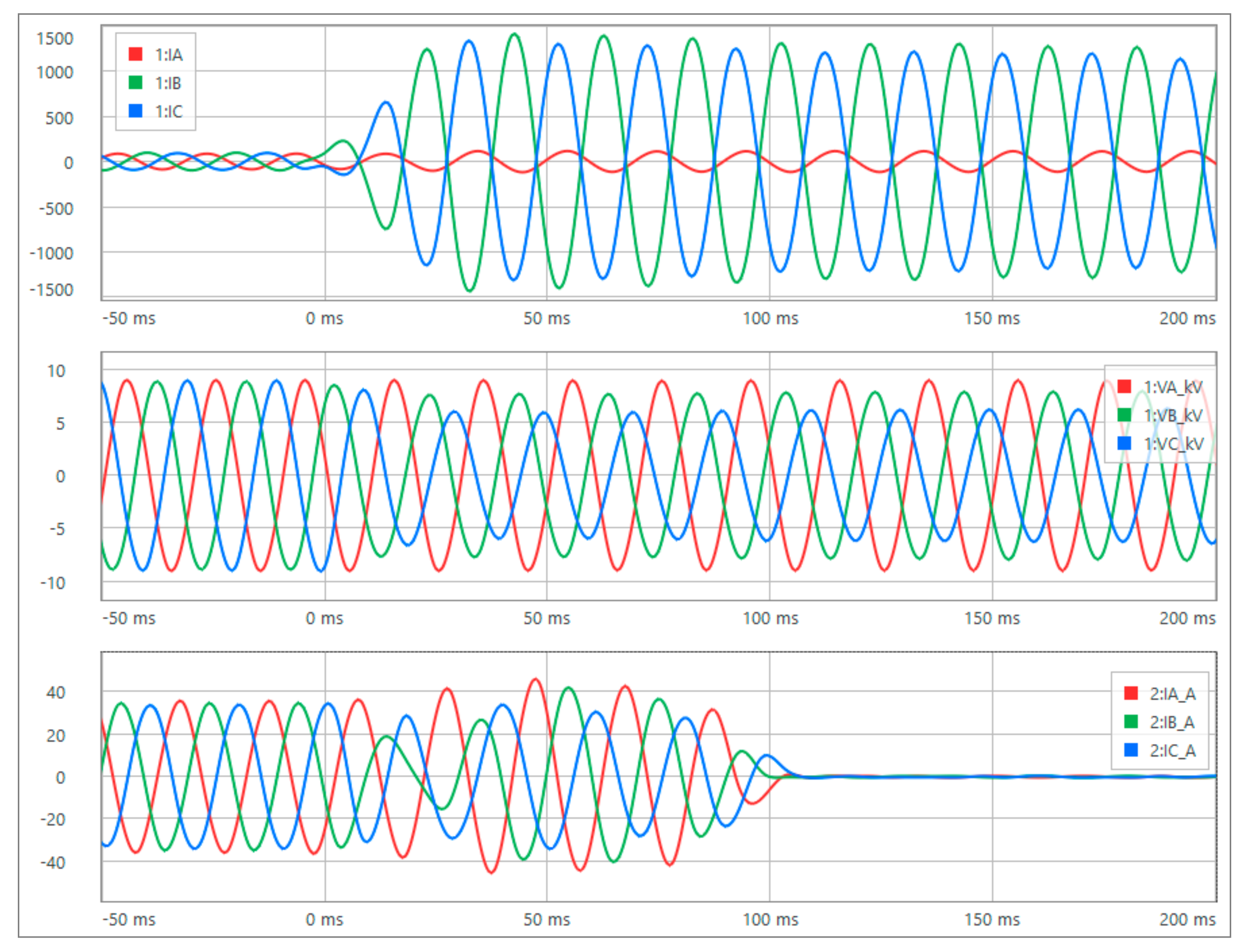
Figure 1, was integrated with an existing utility distribution system. The utility customer opted to install a microgrid in lieu of another transmission line to meet its short-term operating needs. The utility system’s recorded 11 kV voltages and currents, including the fault current for fault at F2 location, through the CB2 and CB21 breakers are shown in
Figure 6. The top chart in
Figure 6 shows the line-to-line fault current through the CB2 breaker.
With this fault scenario, if the microgrid would have remained grid-connected, the voltage disturbance would have ended shortly after CB2 cleared the fault. By that time, however, the microgrid DERs would have been tripped offline by their own protection systems. Since seamless transitions are needed, the microgrid must separate before the DERs trip offline in case the fault was in a location that required islanding. A seamless transition without a voltage interruption is not possible if the DERs trip and are offline when islanding is required.
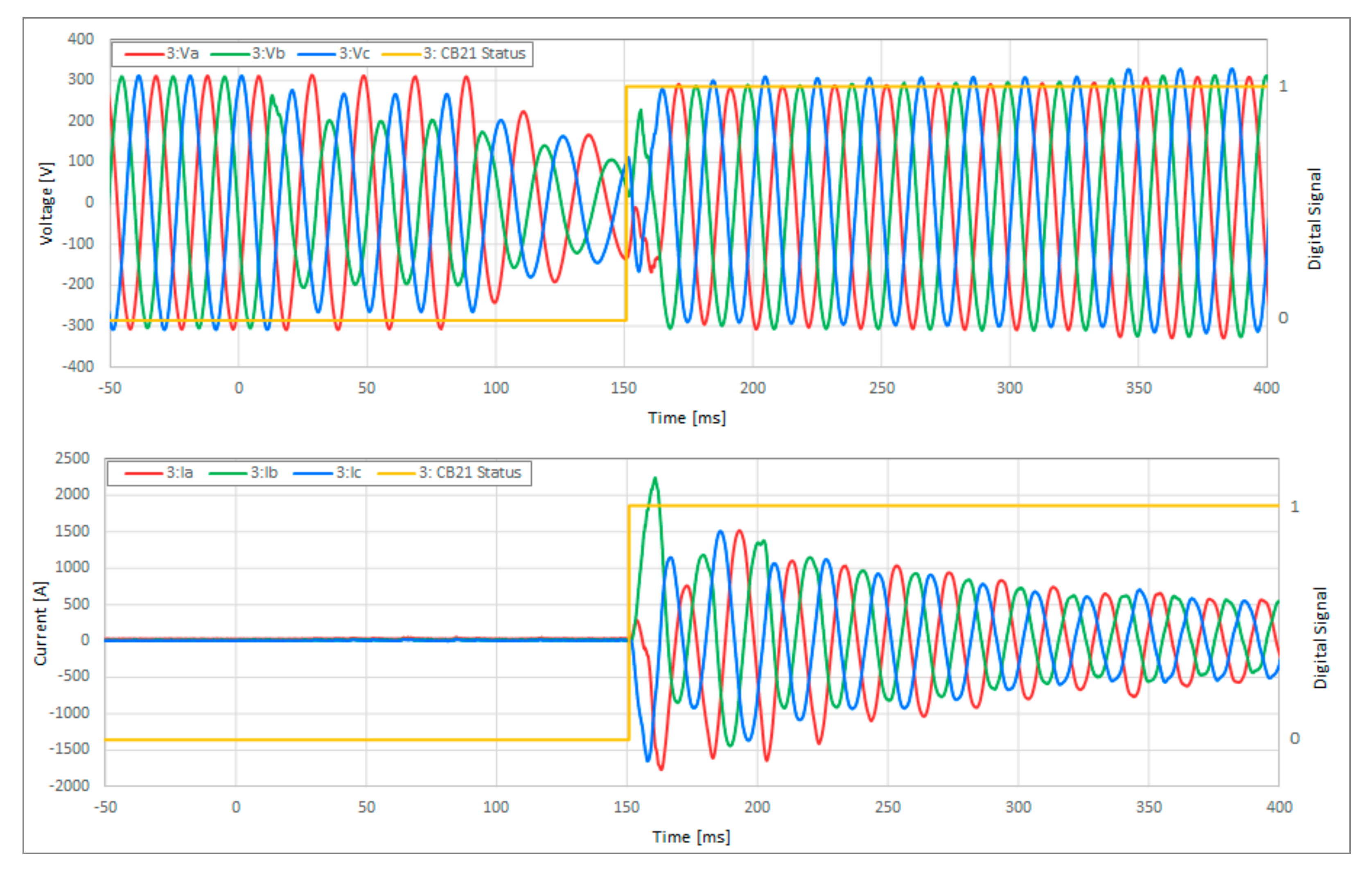
With the implemented protection approach, the BESS’s internal logic detected the utility disturbance, sent a trip signal to the CB21 relay, prepared to transition to a grid-forming (island operation) mode, and waited to receive the CB21 breaker open confirmation signal. Upon receiving the CB21 break open status confirmation (as detailed in
Figure 7), the BESS operated in grid-forming mode and picked up the load within the microgrid. Note that, in
Figure 7, the low and high CB21 Status digital signals denote a breaker close and open, respectively.
Figure 7 shows the terminal voltage and currents of the BESS inverter. The BESS inverter voltages (in
Figure 7) show that the microgrid voltages did not collapse to an interruption and the currents show the BESS inverters successfully picked up the microgrid load during the microgrid transition period.
With the applied protection approach, for conditions and setup at the site at the time of the fault occurrence at the F2 location, the microgrid equipment saw a voltage disturbance from the time of fault inception through the seamless transfer to islanded operation and avoided the impact of a more severe and longer disturbance and a few auto-reclose events that occurred after the initial trip.
4.4. Adequacy of Industry Standards Related to Microgrid Protection
With the growing complexity of connecting DERs to electricity transmission and distribution systems, several local and international interconnection standards were introduced or are being developed: For example, in the US, the North American Electric Reliability Corporation (NERC) Std PRC-024-2 [
44] and the draft IEEE Std 2800 [
45] standards focus on the interconnection of generation to the transmission bulk power system and the IEEE Std 1547: 2018 focuses on the DERs, including bulk supply generation, connected to or embedded in the distribution system, which is the focus of this paper. In GB, there’s the Energy Networks Association (ENA) EREC G99: 2020 [
11] that recommends the requirements for generation equipment connecting to the GB distribution systems. The IEC Technical Specification (TS) 62898-3-1:2020 in Reference [
46] includes protection requirements for microgrids.
The IEEE Std 1547: 2018 is a uniform standard for the interconnection and interoperability of DERs with Electric Power Systems (EPSs) and details a set of requirements relevant to the interconnection and interoperability performance, operation and testing, and to safety, maintenance, and security considerations. The standard categorizes DERs by their steady-state voltage regulation capabilities (as defined in category A or B) and their dynamic capabilities (as defined in category I, II, or III). Where, a higher alphanumerically numbered category has a greater steady-state and dynamic performance capability than a lower numbered category. Although the IEEE Std 1547: 2018 sets out the qualifying requirements for the steady-state (category A or B) and dynamic (category I, II, or III) capabilities for a DER, it does not provide guidance on how the Area EPS operator may specify a set of DER functional parameter settings other than the default settings within the specified ranges of allowable settings, for example, to coordinate with the existing Area EPS protection-and-control devices [
9]. Furthermore, the standard stipulates that the interconnection requirements of DERs or Local EPS at the Point of Common Coupling (PCC), but it does not detail the requirements of DERs during an intentional or microgrid island operation. The responsibility of whether the DERs are allowed to operate and how they are setup, including the selection of their functional parameter settings, within those intentional island grids or microgrids, including when operating in island mode, is left to the Intentional Island Operators (IIOs) or Microgrid Operators (MOs).
Although the IEEE Std 1547: 2018 categorizes DERs based on their performance capabilities as a principal criterion, there are other international standards or engineering recommendations that instead categorize DER based on their active-power capacity as a principal criterion. Furthermore, as such, those standards or engineering recommendations may stipulate the DERs fault ride-through behavior by recommending UV, OV, UF, and OF DER protection settings and or how their protection systems ought to operate.
For example, the ENA EREC G99: 2020 classifies DERs (as Type A to D) based on their generation capacities. Per the ENA EREC G99: 2020, Type A to C DERs are those with a connection point voltage <110 kV and with the following active-power generation capacities: ≥0.8 kW but <1 MW for Type A; ≥1 MW but <10 MW for Type B; and, ≥10 MW but <50 MW for Type C. Moreover, Type D DERs are those with connection point voltage ≥110 kV or a generation capacity of ≥50 MW. The DER capabilities and requirements also increase with the DER type, as it moves from Type A to D. Although the required exact DER voltage and frequency protection settings for all DER types are specified and are similar, if not the same, in the ENA EREC G99: 2020, a principal difference among the DER types is how they trip on the LoM protection. For example, for Type A through C DERs, the LoM protection is based on a RoCoF relay. However, for Type D DERs, an inter-tripping-based protection (based on receiving a trip signal from the utility) is used instead of a LoM protection.
The transmission and distribution systems have competing DER requirements [
47]. For example, from a transmission system’s stability, reliability, and power quality operation point-of-view, the more a DER or a group of DERscan remain online and ride-through a disturbance, the better, particularly those DER that export generation onto the transmission system, either connected to that system directly or embedded in a distribution system. From a distribution system protection and safety point-of-view, however, the faster the short-circuit contributing equipment, including a DER, is disconnected from the system—for example, to limit the short-circuit current at the short-circuited site—the better. Determining an optimum set of functional parameter settings of a DER or a group of DERs, within the defined steady-state and dynamic capability of DERs per IEEE Std 1547: 2018, that meet the requirements of both an Area and a Bulk EPS needs adds to the microgrid design challenge, which requires a careful coordination between the DER site developer, Area EPS personnel, and Bulk EPS personnel to solve it. On the other hand, although the ENA EREC G99: 2020 specifies a DER’s fault ride-through behavior by recommending exact protection settings to be used in each DER type (i.e., Type A through D), the engineering recommendation does not specify DER performance related to UV, OV, UF, and OF protection setting ranges. Although this approach has the benefit of simplicity when it comes to adding a new DER on the power system, it has some disadvantages. For example, if, at a later date, a GB utility chooses to stipulate a different or new set of protection settings to accommodate changing reliability requirements, the already installed DERs, which were procured prior to the change in required protection settings had come into effect, may or may not be able to accommodate the change.
Microgrid systems include DERs, loads, and circuits. They often also include transformers, switchgear, busbars, and other equipment. Presently, there are existing IEEE protection standards offering guidance on how each of these pieces of equipment can be protected. However, microgrid protection involves many unique challenges, as discussed above in
Section 2 and
Section 3. Moreover, there are no existing microgrid specific protection system IEEE standards in the available literature to address microgrid specific unique protection challenges. To address this need and to provide industry guidance on microgrid protection system design, the IEEE Power System Relaying and Control Committee is currently developing the IEEE Std 2030.12, titled “Guide for the Design of Microgrid Protection Systems” [
48].
5. Conclusions
Microgrids offer the benefits of operational flexibility, resiliency, reliability, power quality, accommodation, management, etc., of DERs. However, they are complex, particularly when designing their protection systems. Microgrid protection systems must be designed to accommodate microgrids’ unique operational requirements, such as grid-tied and island modes, while ensuring the safety of the microgrid, microgrid-connected equipment, and personnel at all times and meeting the microgrid’s stability, reliability, and power quality requirements to the greatest extent possible. Although there are a few standards that provide guidance on DER capabilities and interconnection requirements, they are not always applicable or do not always allow for an extensive exploitation of microgrids for the benefits they can offer.
This paper presented a detailed review of the current challenges with protecting microgrids and an overview of several state-of-the-art protection strategies with their respective advantages and disadvantages in addressing those challenges based on the authors’ successful experiences in designing several effective microgrid protection systems globally. The paper also discussed benefits and approaches to switching between protection setting groups with automatic correction as part of adaptive-protection schemes, as well as seamless planned and unplanned microgrid transitions between grid-tied and island modes. These approaches were successfully used in design and implementation of protection systems for several utility-grade, as well as behind the meter microgrids.


 ,
, 


