Article

Analysis and Control of Battery Energy Storage System Based on Hybrid Active Third-Harmonic Current Injection Converter

1
School of Electric Power Engineering, South China University of Technology, Guangzhou 510640, China
2
China Electric Power Research Institute, Nanjing 210003, China
3
School of Electrical Engineering, Southeast University, Nanjing 210096, China
4
State Grid Jibei Electric Power Company Limited, Beijing 100045, China
*
Authors to whom correspondence should be addressed.
Submission received: 21 March 2021 / Revised: 23 May 2021 / Accepted: 25 May 2021 / Published: 27 May 2021

Abstract

:
This paper applies the emerging hybrid active third-harmonic current injection converter (H3C) to the battery energy storage system (BESS), forming a novel H3C-BESS structure. Compared with the commonly used two-stage VSC-BESS, the proposed H3C-BESS has the capability to reduce the passive components and switching losses. The operation principle of the H3C-BESS is analyzed and the mathematical model is derived. The closed-loop control strategy and controller design are proposed for different operation modes of the system, which include the battery current/voltage control and the injected harmonic current control. In particular, active damping control is realized through the grid current control, which could suppress the LC-filter resonance without the need of passive damping resistors. Simulation results show that the proposed topology and its control strategy have fast dynamic response, with a setup time of less than 4 ms. In addition, the total harmonic distortions of battery current and grid currents are only 2.54% and 3.15%, respectively. The amplitude of the injected harmonic current is only half of the grid current, indicating that the current injection circuit generates low losses. Experimental results are also provided to verify the validity of the proposed solution.

1. Introduction

1.1. Background

With the massive penetration of renewable energy resources such as the photovoltaic and wind power, the grid voltage and frequency stability are being threatened because of the high volatility of the renewable energy [1,2]. The battery energy storage system (BESS) has been suggested as a promising solution to suppress the power fluctuations and thus enables more integration of renewable energy [3,4]. In addition, the BESS could also be used to protect important loads from grid fault conditions. Due to these merits, the BESS has attracted tremendous attention worldwide [5,6].

1.2. Motivation

The power conversion system (PCS) is one of the key components of the BESS. The classic PCS solution is the two-stage topology composed of a bidirectional DC–DC converter and a voltage source converter (VSC) [7], as shown in Figure 1. The DC–DC converter enables a flexible combination of low-voltage batteries and the VSC is able to control the active and reactive power at the grid side. In applications where galvanic isolation is required, the DC–DC converter can be implemented by dual active-bridge (DAB) or resonant converters with high-frequency transformers [8,9]. Due to its good controllability at both the grid side and the battery side, the two-stage VSC-BESS is widely adopted in practical applications. However, it suffers from relatively high power loss since both the DC–DC converter and VSC work in high-frequency chopping mode. The single-stage VSC-BESS can be applied to reduce the loss, which directly connects batteries to the DC-link of VSC and eliminates the DC–DC converter [10]. Nevertheless, due to the high voltage at the DC-link of VSC, the single-stage VSC-BESS lacks the flexibility to match different battery voltage level and requires a large number of battery cells in series. The VSC shown in Figure 1 is a two-level topology, which can be replaced with the three-level VSC (3L-VSC) so as to reduce the loss to some extent [11]. For the medium- and high-voltage applications, the cascaded H-bridge converter (CHB) [12,13,14] and modular multilevel converter (MMC) [15,16,17,18] are possible solutions. Batteries can be installed at the DC-link of the sub-modules of CHB or MMC. Benefiting from the modularity and low-switching operation, the reliability and efficiency of CHB and MMC are high. However, they are not cost-efficient solutions for low-voltage applications.
Current source converter (CSC), which is also known as AC–DC matrix converter (MC), has been suggested as a novel solution for BESS. CSC is a buck-type converter from the grid side to the DC-link with a wide DC voltage control range [19]. Similar to the two-stage VSC-BESS, CSC-BESS could also adapt to batteries with different voltages but avoid the need of an additional DC–DC converter. CSC eliminates the large DC-link capacitors and bulky grid side filter inductors, which helps to improve the power density of BESS. In particular, the switching loss of CSC-BESS is much lower than VSC-BESS, because of the single-stage conversion and low voltage stress under commutation, making it a highly efficient solution. When galvanic isolation is required, CSC is also able to output both positive and negative voltages at the primary side of high-frequency transformers, eliminating the need of an additional primary DC–AC converter [20]. However, the extendibility of CSC is relatively low when multi-battery modules need to be integrated.

1.3. Related Work

In recent years, the hybrid active third-harmonic current injection converter (H3C) [21], which is also a buck-type AC–DC converter, has attracted attention. Like CSC, H3C also requires much smaller passive components. Moreover, only a few semiconductor devices work in high-frequency chopping mode while the rest are commutated at very low frequency. In addition, the semiconductor devices on the current path of H3C are less than CSC. Therefore, the achievable efficiency of H3C is much higher than CSC and VSC [22]. To date, H3C is mainly used in unidirectional rectifier applications or the AC–AC conversion system [21,22,23,24,25,26], while its application in BESS has seldom been explored. The existing studies mainly focus on the control performance at the load side, and the active power is mainly flowing through the grid to the load. However, the BESS application requires sufficient bidirectional power flow control capability. In particular, satisfactory control performance in the dynamic process and at the steady state is desired both at the battery side and the grid side. In addition, like other current source converters with a grid-side LC filter [27], the H3C could suffer from filter resonance. Active damping control is preferable to achieve high performance at the grid side, especially for the BESS application. However, the grid side converter of H3C is not fully controllable. As a result, the active damping control has not been practically realized in the literature.

1.4. Contribution of This Paper

Therefore, this paper utilizes the merits of H3C to construct a highly compact and efficient solution for BESS applications. This paper focuses on the operating principle and control strategy of the H3C-BESS, considering the bidirectional power flow and the requirement of control performance at both the battery side and the grid side. In addition, a novel control structure is proposed to achieve the active damping control at the grid side, which is realized both in simulation and experimental results. The proposed active damping control is able to suppress the filter resonance without the need of a passive damping resistor.
The rest of this paper is organized as follows. The system operation principle is analyzed in detail and the mathematical model is derived, which are the main contents of Section 2. The system control strategy regarding the operation mode is proposed and formulated in Section 3. Simulation and experimental results are provided in Section 4 for verifying the effectiveness of this new system associated with the control strategy. Conclusions are drawn in Section 5.

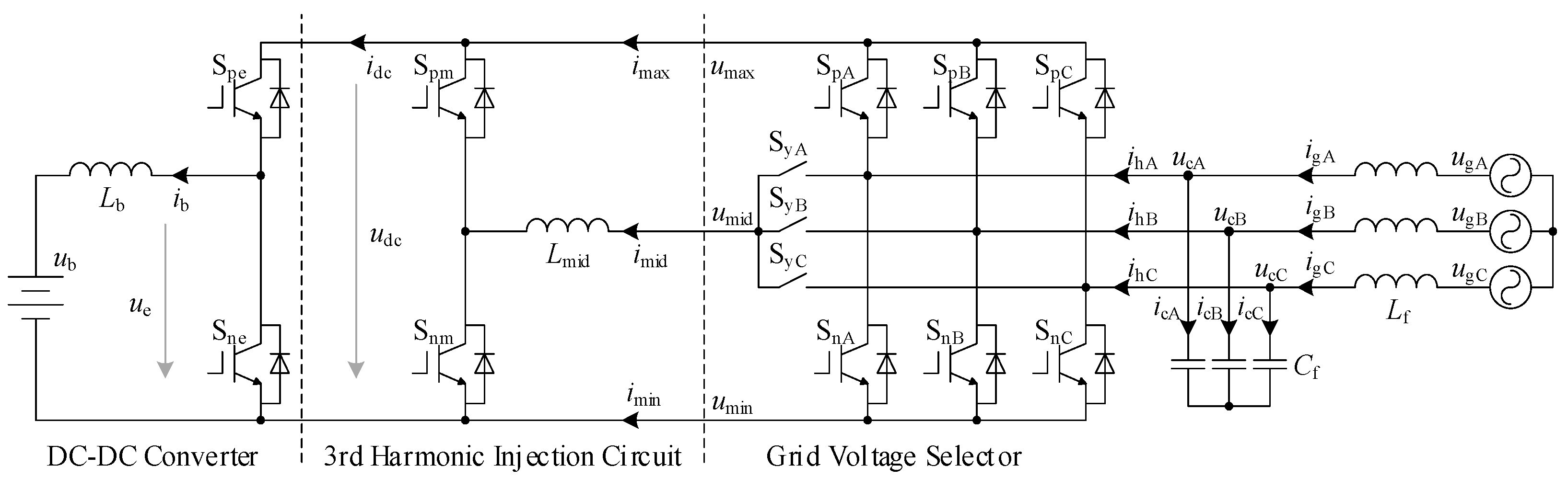
2. Operation Principle and Mathematical Model of H3C-BESS

2.1. System Description

Topology of the H3C-BESS is shown in Figure 2, which is composed of a bidirectional DC–DC converter at the battery side, a third harmonic injection circuit, a grid voltage selector (GVS), and the LC filter at the grid side. The harmonic injection circuit includes a half-bridge and an inductor. The GVS is composed of three-phase bridges and three bidirectional switches. Like the conventional two-stage VSC-BESS, several battery modules can be easily connected to the DC-link of GVS by extending multi-DC–DC converters.
In Figure 2, Spx and Snx denote the upper switch and lower switch of the bridge x (x = e, m, A, B, C) separately. SyA, SyB, SyC represent the bidirectional switch. Lb is the filter inductor at the battery side, Lmid is the filter inductor for the injected harmonic current, Lf is the filter inductor at the grid side, while Cf is the filter capacitor at the GVS side. ub and ib are the battery voltage and current, respectively, while ue is the output voltage of the DC–DC converter. udc is the DC-link voltage and idc is the current flowing into the DC–DC converter. ucA, ucB, and ucC are the capacitor voltages while icA, icB and icC are the currents flowing into the filter capacitor Cf. ugA, ugB, and ugC are the three-phase grid voltages, while igA, igB, and igC represent the grid currents. ihA, ihB, and ihC are the three-phase currents at the GVS side. imax, imid, and imin correspond to the currents flowing out of the GVS.

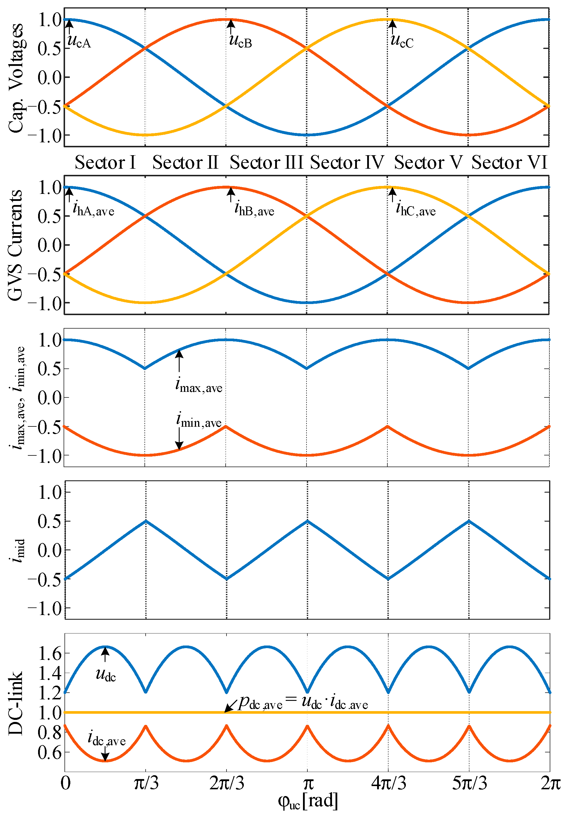
2.2. Operation Principles

As the input of GVS is a voltage source imposed by the filter capacitor Cf, the three-phase bridges in the GVS actually work as a three-phase bidirectional synchronous rectifier. This means that the maximum value (umax) and minimum value (umin) of capacitor voltages (ucA, ucB, ucC) should always be imposed on the positive and negative DC-link, respectively. Accordingly, only the bidirectional switch corresponding to the middle value umid of capacitor voltages can be switched on. The three-phase currents are also determined by the switching states of the GVS, as shown in Table 1, where the sector division is determined by the relationships among the capacitor voltages shown in Figure 3.
As can be found from Figure 1, Figure 3, and Table 1, only the phase current corresponding to the middle phase voltage can be directly controlled through the third harmonic injection circuit, and the remaining two-phase currents are passively determined by the positive and negative DC-link currents of GVS. In addition, it can also be known that the three-phase bridges in GVS are line-commuted, which means their semiconductor devices are switched at the fundamental grid frequency. Similarly, the bidirectional switches in GVS are switched at twice the grid frequency. The half-bridge in the third harmonic injection circuit is switched on/off at the middle current imid, while imid has the minimum absolute value. Therefore, the switching loss of the H3C-BESS is much lower than the VSC-BESS.
The DC-link voltage udc of H3C-BESS is equal to umaxumin, which has large fluctuations even under ideal grid voltages. However, through the real-time correction of the duty cycle of the DC–DC converter, the battery current ib can be regulated at the desired value. Therefore, the DC-link current idc at the buck-converter side also fluctuates while the DC-link active power pdc maintains constant, as shown in Figure 3.
Due to the absence of DC-link passive components, grid currents have to be passively determined by the battery current and the injected harmonic current. However, the battery current is also determined by the control of itself. As a result, the key point of H3C is how to generate sinusoidal grid currents by controlling the third harmonic injection circuit, considering the fact that the transferred instantaneous active power is constant. Under balanced and sinusoidal grid conditions, the three-phase sinusoidal capacitor voltages can be expressed as
{ u cA = u cm cos ( ω g t ) u cB = u cm cos ( ω g t 2 π / 3 ) u cC = u cm cos ( ω g t + 2 π / 3 )
where ucm is the capacitor voltage amplitude. The desired low-frequency components of the GVS currents are expressed as
{ i hA , ave = i hd cos ω g t + i hq sin ω g t i hB , ave = i hd cos ( ω g t 2 π / 3 ) + i hq sin ( ω g t 2 π / 3 ) i hC , ave = i hd cos ( ω g t + 2 π / 3 ) + i hq sin ( ω g t + 2 π / 3 )
where ihd and ihq are the active and reactive components of GVS currents, respectively.
Take Sector I as an example to illustrate how H3C can generate sinusoidal grid currents, namely ωgt in (1) is within [0, π/3]. In this case, umax, umid and umin satisfy:
u max = u cA , u mid = u cB , u min = u cC
Therefore, the DC-link voltage and current are:
{ u dc = u max u min = u cA u cC i dc , ave = p dc ,   ave u dc = p dc ,   ave u cA u cC
where Pdc, ave is the average instantaneous active power transferred from the DC–DC converter.
Since umaxumidumin, the half-bridge in the third harmonic injection circuit is fully controllable and the actual current imid flowing through the inductor Lmid can be considered equal to its reference. In this case, it is:
i mid = i hB , ave
Supposing the duty cycle of the upper switch Spm in the half-bridge is dm, the following equation is obtained based on the voltage-second balance of Lmid at the steady state:
d m u max + ( 1 d m ) u min = u mid
and thus:
d m = u mid u min u max u min
According to Figure 2, the current imax satisfies:
i max = i dc d m i mid
To achieve sinusoidal grid currents, imax in this case should be equal to its reference ihA, ave:
i max = i hA , ave = i hd cos ω g t + i hq sin ω g t
By substituting (1)–(8) into (9), the condition for (9) is resolved:
i hd = 2 p dc ,   ave 3 u cm
Therefore, only if the active component ihd of GVS currents is set based on (10) and the current imid is controlled to its reference value shown in (5), both the phase A and B currents can reach sinusoidal, and phase C is naturally sinusoidal because the sum of ihA, ihB and ihC is always 0. Note that (10) is irrespective with ihq, which means that the reactive power can be theoretically controlled to any desired value. When the capacitor voltages fall into other sectors, the operation principle can be analyzed in a similar way.

2.3. Mathematical Model

Equations presented in Part B of this section are sufficient to analyze the operation principle, but they do not include the dynamic behavior of the system. In order to formulate the system closed-loop control strategy, the mathematical model of H3C-BESS is developed.
According to Figure 2, the battery current ib satisfies:
L b d i b d t = d e ( u max u min ) R b i b u b
where de is the duty cycle of the upper switch Spe of the DC–DC converter; Rb is the parasitic resistance of the filter inductor Lb. The DC-link current idc at the DC–DC converter side is thus expressed as
i dc = d e i b
The current imid in the third harmonic injection circuit satisfies:
L mid d i mid d t = ( u mid u min ) ( u max u min ) d m R mid i mid
where Rmid is the parasitic resistance of the filter inductor Lmid. The current imax can thereby be expressed as
i max = i dc d m i mid
The current imin always satisfies:
i min = ( i max + i mid )
The GVS currents ihA, ihB, and ihC are determined by imax, imid, and imin according to the switching states of GVS listed in Table 1. Grid currents (igA, igB, igC) and capacitor voltages (ucA, ucB, ucC) satisfy:
{ L f d i gX d t = u cX u gX R f i gX C f d u cX d t = i hX i gX , X = { A , B , C }
where Rf is the parasitic resistance of the filter inductor Lf. Together with Table 1, (11)–(16) construct the mathematical model of the proposed H3C-BESS, which can be used for designing the closed-loop control strategy. It should be noted that the relations shown in Table 1 make the H3C-BESS highly nonlinear. Therefore, only the piecewise linear model is available. Additionally, approximation needs to be applied when designing the controllers.

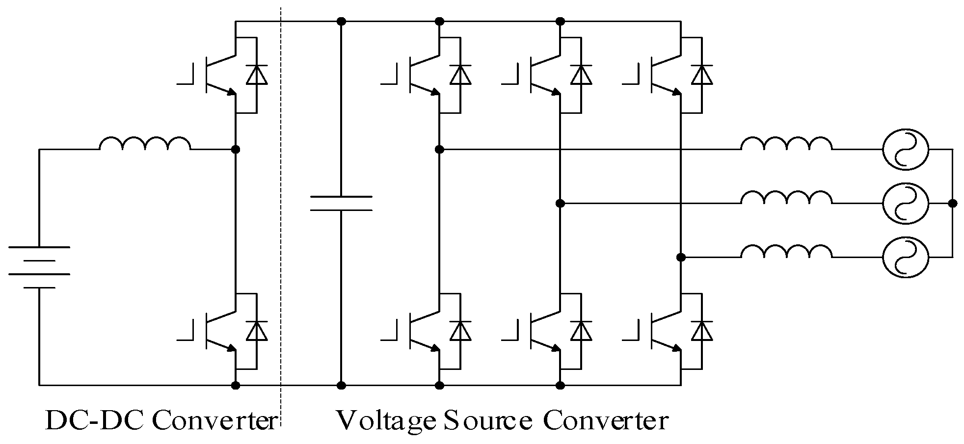
2.4. Comparison with Two-Stage VSC-BESS

The two-stage VSC-BESS has been widely adopted in practice. Therefore, it is necessary to compare the novel H3C-BESS with the VSC-BESS, so as to highlight its features. As it can be seen from Figure 1 and Figure 2, the H3C-BESS has the following differences from the view of topology:
  • The H3C-BESS does not need large capacitors at the DC-link of H3C-BESS [21], while a bulky capacitor is required at the DC-link of VSC-BESS;
  • The grid side filter of H3C-BESS is a second-order LC filter, which is also much smaller than the filter inductor of VSC-BESS [28];
  • An additional inductor Lmid is required in H3C-BESS. However, the maximum current flowing through it is only half of the grid current amplitude, as shown in Figure 3;
  • The H3C-BESS requires 14 transistors (each bidirectional switch requires two transistors in practice). The VSC-BESS requires only eight transistors.
Therefore, the H3C-BESS requires more components and semiconductor chip area than the two-stage VSC-BESS. However, H3C-BESS could reduce the volume and weight of passive components. Moreover, the switching loss of H3C-BESS is much lower than VSC-BESS:
  • Under the same input voltage, battery voltage and current, the DC–DC converter in H3C-BESS generates less switching loss than H3C-BESS, because the DC-link voltage of H3C-BESS is smaller than H3C-BESS [21];
  • The GVS part in H3C-BESS transfers the main power. However, the switching frequency is quite low, only the fundamental or twice the grid frequency. Compared with the VSC operating at high switching frequency, the switching loss generated by GVS is ignorable [23];
  • Although the half-bridge in the harmonic injection circuit works in chopping mode, the maximum chopped current is only half of the grid current amplitude. Therefore, the generated switching loss is also very small [21].
In summary, compared with the two-stage VSC-BESS, the H3C-BESS has the advantages of high power density and high efficiency if optimally designed, especially when the battery voltage is low. However, its drawback is the requirement of more components, which could result in higher cost in practice.

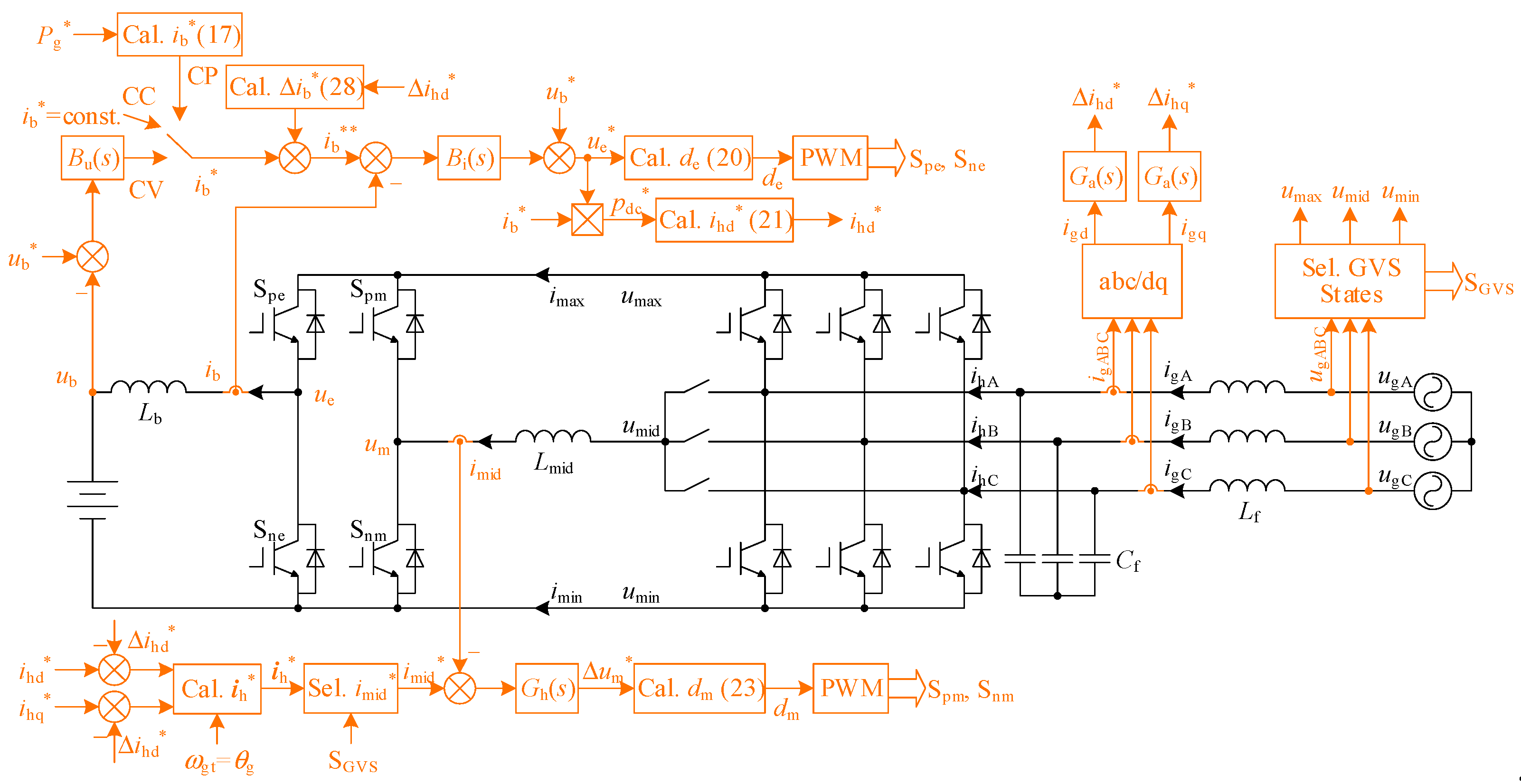
3. Proposed Control Strategy for H3C-BESS

3.1. Control Block Diagram

Subject to the power requirement of the grid and the state of charge (SOC) of batteries, the H3C-BESS could operate at three modes: constant current (CC), constant voltage (CV), and constant power (CP). In CP mode, the SOC of the battery is in the normal range (e.g., 20%–80%), and the battery can transfer active power to or absorb from the grid. CC and CV modes are activated to prevent battery damage due to excessive charge or discharge.
In contrast to the conventional two-stage VSC-BESS in which the large DC-link capacitor is able to isolate the battery and grid, the H3C-BESS directly couples the battery and grid. Therefore, the grid active power is always equal to that generated or absorbed by the battery, if the power loss could be ignored. The harmonic injection circuit has few influences on the transmitted active power but is able to make grid currents sinusoidal by changing the active power distribution among three phases.
Based on the operation principle analyzed in Section II, the system closed-loop control strategy is proposed for H3C-BESS, as shown in Figure 4. The proposed strategy measures grid voltages and further determines the switching states SGVS of GVS based on Table 1. The sorted grid voltages umax, umid, and umin are also selected based on Table 1. The battery current control is always the dominant loop of the system control strategy, irrespective of the operation mode, while the reference current ib* is set based on the operation mode. In CC mode, ib* is constant. In CV mode, ib* is generated from the closed-loop control of the battery voltage. In CP mode, ib* is calculated with the desired grid active power Pg*. The closed-loop control of battery current generates the active current reference ihd*. The reactive current reference ihq* could be fixed at zero for simplicity. In particular, active damping control is realized by regulating the grid currents with proper controllers, which generates signals ihd* and ihq* to modify the references of battery current and injected harmonic current. The remaining parts of this section will describe the proposed control strategy in detail.

3.2. Control of Battery Current and Voltage

The single-loop current control is applied to the battery in CC mode, where the reference ib* is set constant. In CV mode, the double-loop voltage and current control is applied, and thus ib* is generated from the voltage control. In CP mode, ib* is calculated with the desired grid active power Pg* with the converter efficiency taken into consideration:
i b * = { η P g * u gm , P g * 0 P g * η u gm , P g * < 0
where positive Pg* means the battery absorbs active power from the grid while negative Pg* indicates the inverse direction.
The control structure at the battery side is similar to the two-stage VSC-BESS. The typical proportional–integral (PI) controllers can be utilized to regulate the battery current and voltage, namely controllers Bi(s) and Bu(s) are expressed as
B i ( s ) = K pbi + K ibi / s
B u ( s ) = K pbu + K ibu / s
where Kpbi and Kipi are the static gain and integral gain of the current controller; Kpbu and Kipu are the static gain and integral gain of the voltage controller. The control parameters can be tuned based on the typical first-order system, which is mature for power converters.
However, the DC-link voltage in H3C-BESS is not constant as that in two-stage VSC-BESS, and thus feedforward control is indispensable when calculating the duty cycle of the DC–DC converter. The output of Bi(s) represents the reference voltage drop on Lb. Accordingly, adding the output of Bi(s) and the battery voltage ub generates the reference voltage ue* that the DC–DC converter should output. The duty cycle de of the switch Spe is further calculated by
d e = u e * u dc = u e * u max u min
The typical PWM technique for the DC–DC converter is then applied to generate the gate signals of Spe and Sne.
It should be noted that the feedforward control is able to suppress the influence of DC-link voltage fluctuation on the battery current. Therefore, any grid voltage disturbance (such as unbalance or distortions) can be prevented from transferring into the battery.

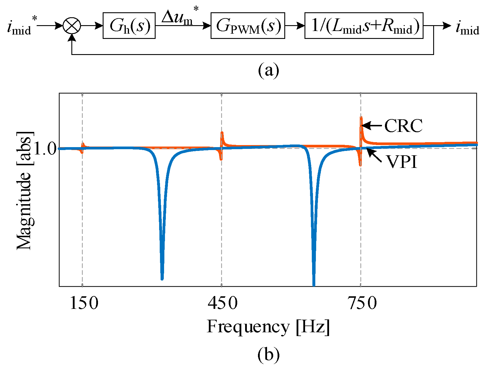
3.3. Control of Injected Harmonic Current

For the harmonic injection circuit, the reference current imid* is selected from the reference GVS currents (ihA*, ihB*, ihC*) according to Table 1. The reference GVS currents can be obtained based on (2), where ihd* is calculated from the reference active power generated by the closed-loop control of battery current:
i hd * = { 2 i b * u e * 3 η u gm i b * 0 2 η i b * u e * 3 u gm i b * < 0
where the capacitor voltage amplitude ucm is approximated by the grid voltage amplitude ugm. As it is shown in Figure 3, the reference current imid* is similar to a triangular wave with the frequency of 3 ωg, which means it contains harmonics with frequencies of 3ωg, 9ωg, 15ωg, etc. To regulate such a kind of harmonic current, the controller Gh(s) is designed as N vector-proportional–integral (VPI) controllers in parallel:
G h ( s ) = n = 1 N K ph n s 2 + K ih n s s 2 + [ 3 ( 2 n 1 ) ω g ] 2
where Kphn and Kihn are the static gain and resonant gain of the nth VPI controller. It can be known from Fourier series of the triangular wave that the content of the harmonic at the frequency of 21ωg or higher is less than 2% which has quite a limited effect on the grid current. Therefore, three VPI controllers (i.e., n = 3) are sufficient to regulate the injected harmonic current without generating observable steady-state errors.
The output of Gh(s) represents the reference voltage drop ∆um* on the inductor Lmid, and thus the duty cycle of switch Spm can be calculated based on (13):
d m = u mid u min Δ u m * u max u min
The typical PWM technique for the half-bridge is then applied to generate the gate signals of Spm and Snm.
The closed-loop control structure of the injected harmonic current is shown in Figure 5, where GPWM(s) = 1/(1.5Tss+1) and Ts denotes the sampling time. Similar to the design criteria of the typical PI controller which realizes zero-pole cancellation, parameters of the VPI are set as
K ph n = L mid 3 T s , K ih n = R mid 3 T s
Note that the expression of the VPI controller is similar to the common resonant controller (CRC). VPI and CRC have the same poles at the desired frequencies but have different numerators. Frequency responses of the closed-loop transfer function with VPI and CRC are shown in Figure 5b. It can be seen that, with CRC, undesired resonant peaks around the central frequencies are generated. In practice, the utility grid usually has a frequency variation up to 0.2 Hz. Therefore, such undesired peaks will result in the inaccurate control of the injected harmonic current and further undesired low-frequency harmonics in the grid currents. On the contrary, the frequency response with VPI is quite smooth around the central frequencies, without any undesired peaks. Therefore, VPI is more robust than CRC in practice considering the grid frequency variation.
It can be known from (21), generating the reference of the injected harmonic current is an open-loop method. In practice, precise parameters are unavailable, especially considering that the converter efficiency is variable with the working conditions. Under parameter uncertainties, the obtained reference of the injected harmonic current could be inaccurate. It can be inferred from Part B Section 2 that the inaccurate injected harmonic current directly leads to the deviation of the grid currents from the desired sinusoidal currents. As a result, the actual grid currents are distorted, reducing the power quality. Figure 6 shows the grid currents under different inaccuracies of injected harmonic current. It is clear that the inaccuracies directly result in grid current distortions. It should be noted that, the effect of input LC filter is ignored in Figure 6. The LC filter in practice could enlarge the harmonics in grid currents, leading to higher distortions.

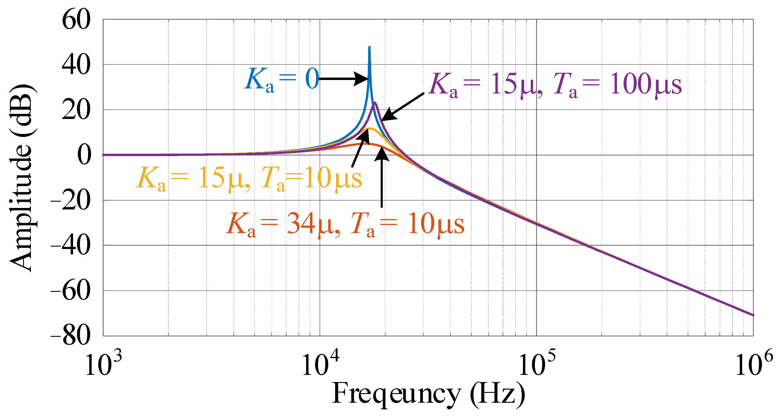
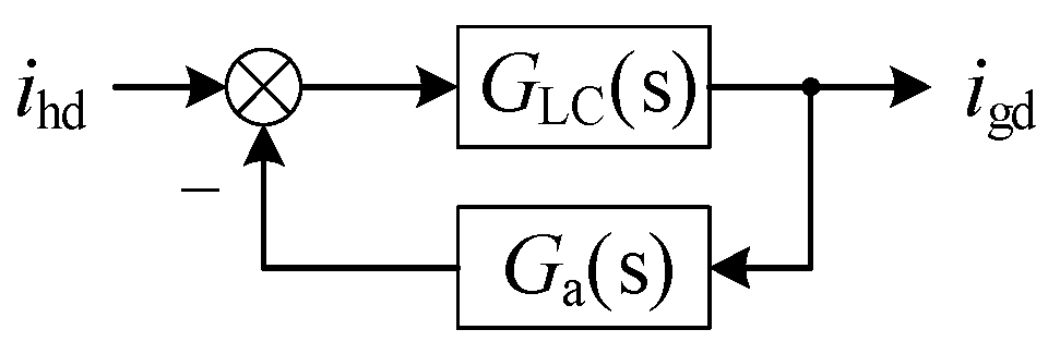
3.4. Active Damping Control

Theoretically, according to the active power balance principle of H3C, grid currents could always be indirectly regulated without a closed-loop control. This helps to reduce the tuning effort of the controller. However, it is still beneficial to incorporate a closed-loop control of grid currents, so as to achieve an active damping function.
According to Figure 4, the transfer function from the GVS currents ihd and ihq to the grid currents igd and igq is determined by the grid-side LC filter, expressed as
G LC ( s ) = 1 L f C f s 2 + R f C f s + 1
where Rf is the parasitic resistance of the filter inductor. In practice, Rf is usually quite small, making GLC(s) a weakly damped second-order system. The frequency response of GLC(s) is shown in Figure 7. It is clear that without additional damping control, GLC(s) has a very high resonant peak. The PWM control of the converter could easily inspire the resonance of the grid-side filter, which deteriorates the input power quality.
Therefore, additional damping control is indispensable for H3C. Usually, paralleling a damping resistor with the filter inductor Lf has good damping performance. However, the passive damping resistor generates power loss and increases the high-frequency harmonics in grid currents. As a result, it is preferable to adopt active damping control which suppresses the filter resonance through the control strategy.
In the proposed control strategy shown in Figure 4, the active damping function is realized by the closed-loop control of grid currents, where the controller is termed as Ga(s). The closed-loop control structure of grid currents is shown in Figure 8. It can be noted that the controller Ga(s) is located at the feedback path rather than the forward path. From Figure 8, the closed-loop transfer function is obtained:
H LC ( s ) = G LC ( s ) 1 + G LC ( s ) G a ( s )
Clearly, by designing proper Ga(s), it is possible to reshape the frequency response of GLC(s). In this paper, Ga(s) is designed as
G a ( s ) = K a s T a s + 1
where the differential term with the coefficient Ka at the numerator contributes to the active damping function. As the differential operation could enlarge the high-frequency noise and harmonics in practice, it is necessary to include the low-pass filter in (27) with the time constant as Ta. Frequency responses of HLC(s) with different values of Ka and Ta are plotted in Figure 7. It can be concluded that the larger Ka and the smaller Ta are, the better damping performance is achieved. However, large Ka and small Ta mean large feedback signal, which could affect the normal operation of H3C-BESS. Therefore, trade-off should be made when selecting the values of Ka and Ta in practice.
As shown in Figure 4, controllers Ga(s) at the dq axis generate the additional reference signals ∆ihd* and ∆ihq*. Theoretically, ∆ihd* and ∆ihq* should be used to modify the GVS current references ihd* and ihq*. However, as presented in Section II, the injected harmonic current can only influence parts of the GVS current. For the complete realization of the active damping function, the reference battery current should also be modified with:
Δ i b * = 1.5 Δ i hd * u gm u b
where the converter efficiency is assumed to be unity for simplicity.

4. Simulation and Experimental Verification

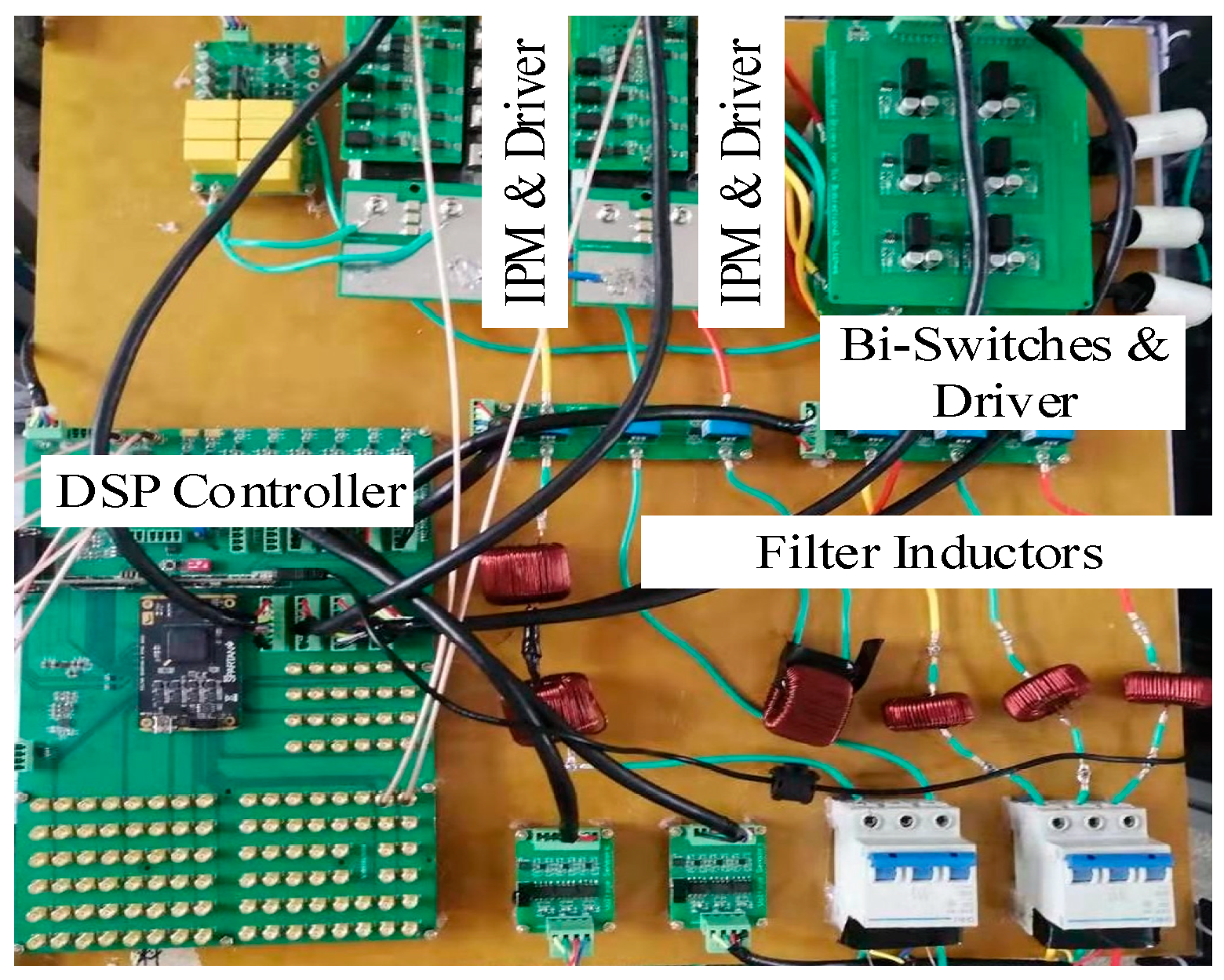
4.1. Prototype and Parameters

To verify the effectiveness of the H3C-BESS associated with the proposed system control strategy, a prototype of H3C is constructed. A photograph of the prototype is shown in Figure 9 and the experimental parameters are listed in Table 2. The GVS uses an intelligent power module (IPM) with part number PM25RLA120, while the switching frequency is 50 Hz. The DC–DC converter and the harmonic circuit shares one IPM with the same part number and their switching frequency is 16 kHz. The bidirectional switches are constructed using the discrete IGBT with part number IKW15N120H3 which are switched at 100 Hz. The digital signal processor (DSP) is TMS320F28379D with dual cores, which is powerful enough to handle all the computation. A large capacitor (5 mF) is used to emulate the behavior of the battery. The control parameters are optimally designed according to the filter parameters.
The corresponding simulation model was built in Matlab/Simulink. The simulation parameters are the same with those used in experiments, as listed in Table 2. A capacitor serves as the battery in CC and CV mode and is replaced with a constant voltage source in the CP mode, which is conducive to shorten the simulation time.

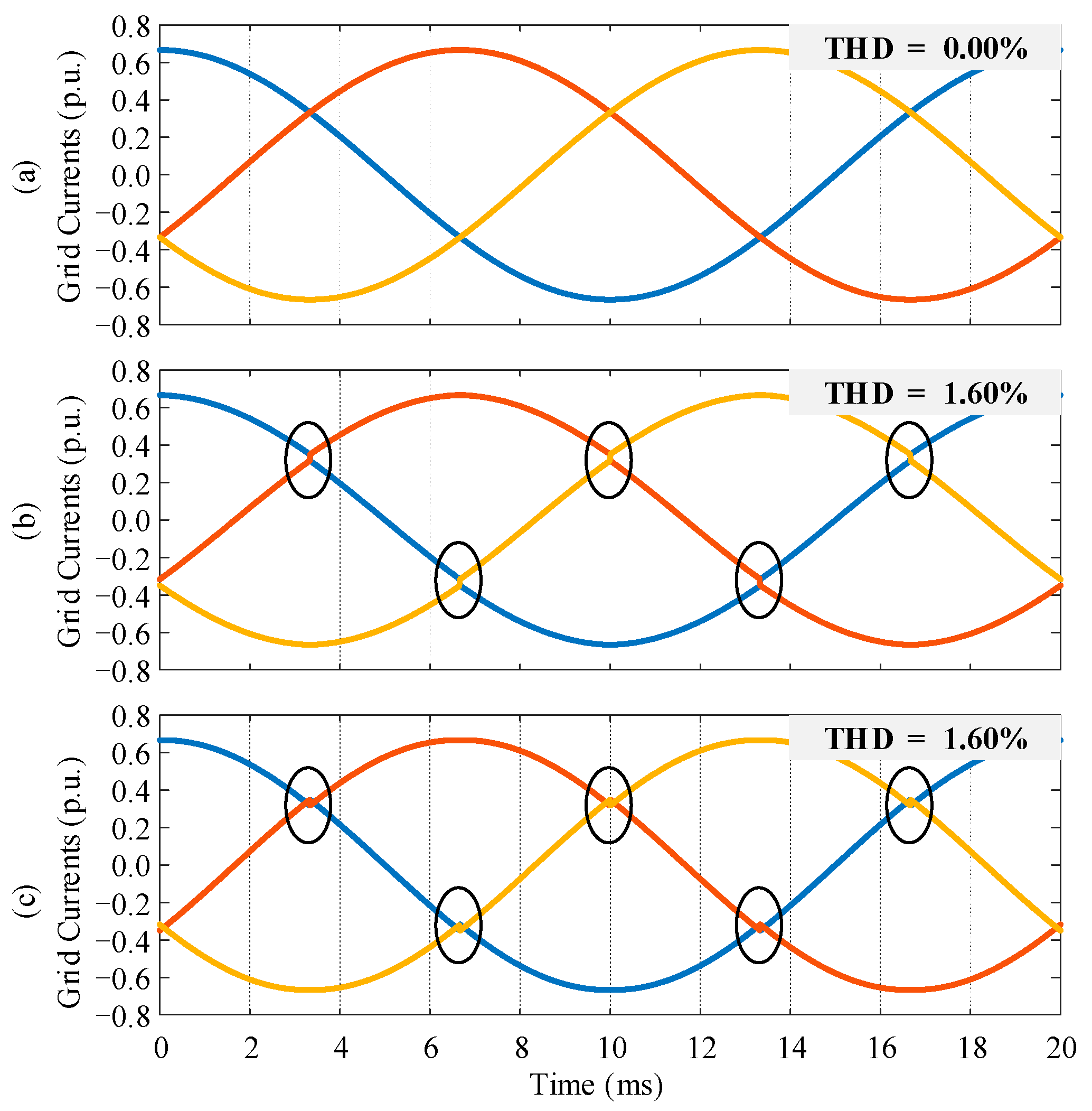
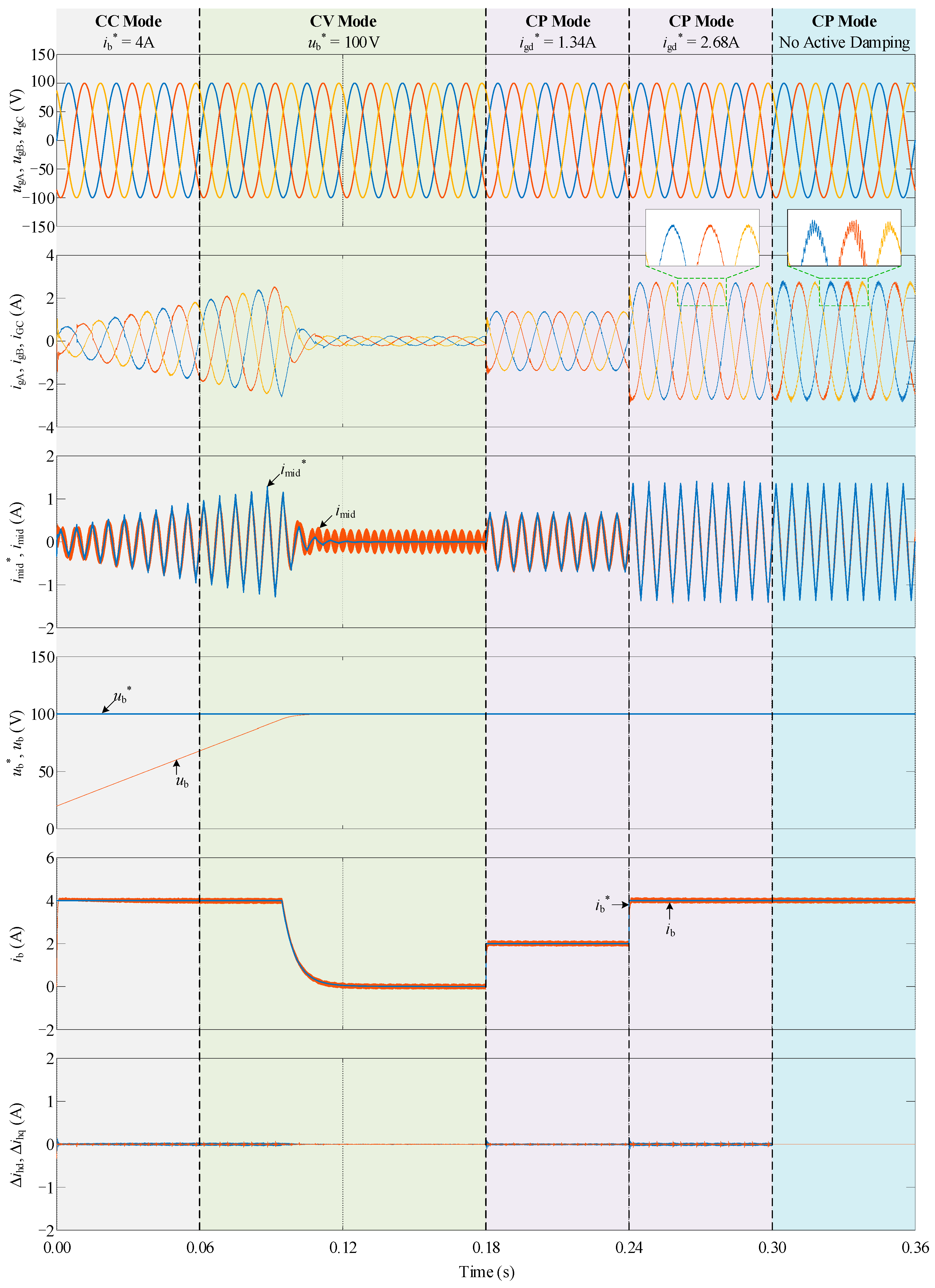
4.2. Simulation Results

The simulation results are shown in Figure 10. From 0.00 s to 0.06 s, the H3C-BESS works in CC mode with reference battery current ib* fixed at 4 A. From 0.06 s to 0.18 s, the system works in CV mode with the reference battery voltage fixed at 100 V. Between 0.18 s and 0.30 s, the system works in CP mode, with grid current reference stepping from 1.34 A to 2.68 A (the battery current stepping from 2 A to 4 A accordingly). During the remaining 0.06 s, the system is maintained in CP mode but the active damping function is removed.
As it is shown in Figure 10, the battery current ib can always track its reference ib* during the steady state and the dynamic response is very fast with few overshoots. The setup time of the battery current is less than 4 ms. As for the battery voltage, it can also reach its reference with the expected trajectory. This indicates that the satisfactory performance of battery current and voltage control can be achieved by the H3C-BESS with the proposed system control structure. Note that the total harmonic distortion (THD) of the battery current ripple during the steady state is 2.54%, which can be further reduced by increasing the filter inductor Lb or switching frequency.
As is the case for the battery current, the injected harmonic current imid can also tract its reference imid* without steady-state error and with a fast dynamic response. This shows that the adoption of multi-VPI controllers has achieved the desired control performance. Note that the amplitude of the low-frequency component of imid is only half of the grid current. As the switching loss of the power converter is proportional to the operating current, it can be expected that the third harmonic injection circuit generates only a few switching losses. In addition, increasing the filter inductor Lmid or the switching frequency is also able to reduce the high-frequency ripple of imid.
The grid currents automatically vary with the working operation modes and the current demands. Moreover, the grid current amplitude responds very fast and smoothly to its reference. The setup time is also less than 4 ms. The THD of grid currents is 3.15%. This demonstrates that the H3C-BESS exhibits satisfactory control performance at the grid side, without the need for PI controllers to regulate the grid current. This is an evidence that the H3C-BESS has lower control complexity than the two-stage VSC-BESS which must have multi-loop control for grid currents. It can be observed from the waveforms that the grid currents have some distortions at the sector boundary. This is a common issue of the H3C based converter system and could be addressed with rearranged filters and an additional control [29].
In CC mode, the battery current is maintained as constant through the closed-loop control, while the battery voltage is increasing. Therefore, the active power flow to the battery is always increasing in CC mode, resulting in the increase in grid currents and the injected harmonic current. In practice, to avoid overcharging the batteries, CV control must be applied when the battery voltage reaches the predefined threshold. In CV mode, the battery voltage still increases and finally reaches the reference value. The battery current is maintained as constant firstly and then dropped gradually to zero until the battery voltage reaches the steady state. As a result, the transferred active power, grid currents and the injected harmonic current also increase firstly and then drop to zero. Therefore, all the waveforms in Figure 10 are consistent with the theoretical analysis.
With the proposed active damping control, the grid currents are very smooth and sinusoidal. The generated additional signals ∆ihd* and ∆ihq* are very small compared with ib and imid, and thus have few influences on the normal operation of H3C-BESS. When the active damping control is disabled, significant oscillations are contained in the grid currents. This proves that additional damping control is necessary for the H3C-BESS and the proposed active damping control works correctly.

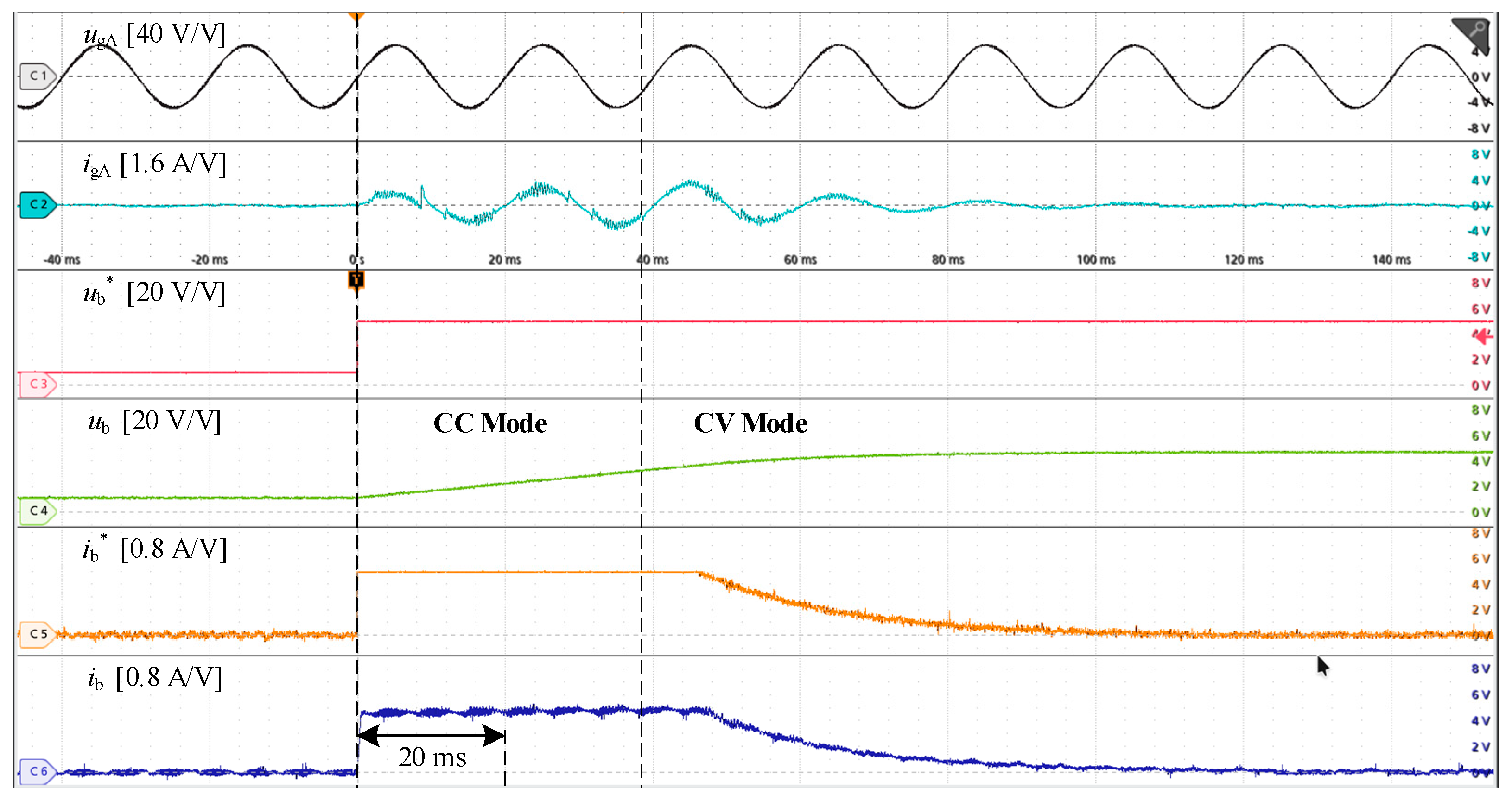
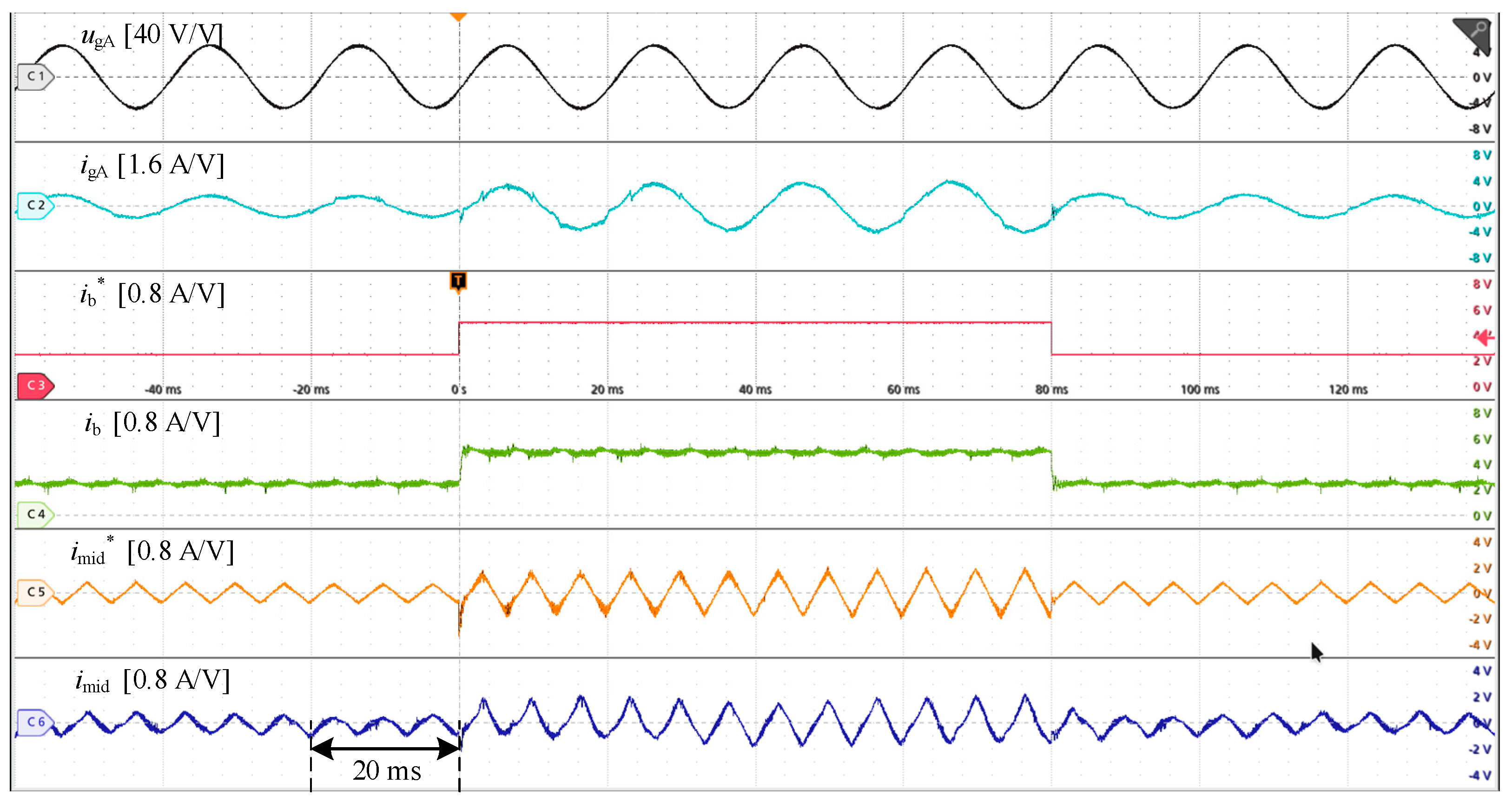
4.3. Experimental Results

In experiments, it was found that the overcurrent protection scheme of the prototype is easily triggered when the active damping function is disabled. Therefore, the active damping control is always included in the algorithm. The experimental results in CC mode and CV mode are shown in Figure 11. When the CC mode is activated, the reference battery current ib* is fixed at 4A. The actual battery current ib reaches ib* very quickly without overshoot. In the CV mode, the voltage control loop is activated, which generates ib*. Due to the saturation of the PI controller, ib* is maintained at 4A for a short time and then decreases gradually to zero. Waveforms in the experimental results are almost the same with those obtained in simulation, which is another evidence that the H3C-BESS with the proposed control strategy works correctly in CC mode and CV mode.
Experimental results in the CP mode are shown in Figure 12. In this mode, the reference battery current ib* is calculated from the grid current reference igd* in an open-loop way. ib* steps between 2 A and 4 A. It can be found that, in CP mode, both the battery current and the grid currents have a fast and relatively smooth dynamic response, proving that the proposed control strategy achieves good dynamic performance. Compared with the simulation results, more harmonics are contained in the grid currents. As presented in Part C Section 3, this is mainly because the reference value of the injected third harmonic current is calculated in an open-loop way. The inaccurate system parameters (especially the efficiency) result in the error of the reference harmonic current, which generates the distortion in grid currents. This is a common issue for this kind of converters. In previous publications [21,23], it can also be found that the grid currents are more or less distorted.
The measured efficiency of the prototype is about 92%, which can be improved by optimizing the selection of active and passive components. In summary, waveforms of the harmonic current are consistent with the theoretical analysis, demonstrating the operation principle of H3C-BESS.

5. Conclusions

This paper successfully applied the H3C to the BESS applications, forming a novel H3C-BESS. Compared with the commonly used two-stage VSC-BESS, the H3C-BESS has the capability to reduce the passive components and switching losses. The operating principle of H3C-BESS was analyzed in detail. The system control structure is proposed for the H3C-BESS. In particular, active damping control was realized through the grid current control, which could suppress the LC-filter resonance without the need of passive damping resistors. Simulation results proved that the proposed solution has a fast dynamic response with a setup time of less than 4 ms. In addition, the steady-state performance was also satisfactory with THDs of battery current and grid currents at 2.54% and 3.15%, respectively. The amplitude of the injected harmonic current is only half of the grid current, indicating that the corresponding circuit could generate low losses. Experimental results provided in this paper have also demonstrated the effectiveness of the H3C-BESS with the proposed system control strategy. It can be expected that the proposed H3C-BESS will be a promising solution in the BESS applications.
Closed-loop generation of the reference harmonic current is helpful to reduce the grid current distortions. In addition, the comprehensive comparison between H3C-BESS and the typical two-stage VSC-BESS is necessary to further demonstrate the advantages of H3C-BESS. These are all meaningful works in future studies.

Author Contributions

Conceptualization, Y.T. and J.L.; methodology, J.L. and Q.H.; software, X.F. and T.C.; validation, X.F. and J.L.; formal analysis, J.L.; investigation, Q.H.; resources, J.L. and W.C. data curation, J.L.; writing—original draft preparation, J.L.; writing—review and editing, Q.H.; visualization, X.F.; supervision, Y.T., W.C.; project administration, Y.T., J.L. and Q.H.; funding acquisition, J.L., Q.H., and W.C. All authors have read and agreed to the published version of the manuscript.

Funding

This work was supported in part by the National Key Research and Development Project of China under Grant 2020YFF0305800, in part by the Natural Science Foundation of Jiangsu Province of China under Grant BK20180396, and in part by the Zhishan Young Scholar Program of Southeast University.

Conflicts of Interest

The authors declare no conflict of interest.

References

  1. Wei, S.; Zhou, Y.; Huang, Y. Synchronous Motor-Generator Pair to Enhance Small Signal and Transient Stability of Power System with High Penetration of Renewable Energy. IEEE Access 2017, 5, 11505–11512. [Google Scholar] [CrossRef]
  2. Aliabadi, S.F.; Taher, S.A.; Shahidehpour, M. Smart Deregulated Grid Frequency Control in Presence of Renewable Energy Resources by EVs Charging Control. IEEE Trans. Smart Grid 2018, 9, 1073–1085. [Google Scholar] [CrossRef]
  3. Azizivahed, A.; Arefi, A.; Ghavidel, S.; Shafie-Khah, M.; Li, L.; Zhang, J.; Catalao, J.P.S. Energy Management Strategy in Dynamic Distribution Network Reconfiguration Considering Renewable Energy Resources and Storage. IEEE Trans. Sustain. Energy 2020, 11, 662–673. [Google Scholar] [CrossRef]
  4. Zhu, Y.; Liu, C.; Sun, K.; Shi, D.; Wang, Z. Optimization of Battery Energy Storage to Improve Power System Oscillation Damping. IEEE Trans. Sustain. Energy 2019, 10, 1015–1024. [Google Scholar] [CrossRef] [Green Version]
  5. Faisal, M.; Hannan, M.A.; Ker, P.J.; Hussain, A.; Bin Mansor, M.; Blaabjerg, F. Review of Energy Storage System Technologies in Microgrid Applications: Issues and Challenges. IEEE Access 2018, 6, 35143–35164. [Google Scholar] [CrossRef]
  6. Stecca, M.; Elizondo, L.R.; Soeiro, T.; Bauer, P.; Palensky, P. A Comprehensive Review of the Integration of Battery Energy Storage Systems into Distribution Networks. IEEE Open J. Ind. Electron. Soc. 2020, 1, 1. [Google Scholar] [CrossRef]
  7. Vazquez, S.; Lukic, S.M.; Galvan, E.; Franquelo, L.G.; Carrasco, J.M. Energy Storage Systems for Transport and Grid Ap-plications. IEEE Trans. Ind. Electron. 2010, 57, 3881–3895. [Google Scholar] [CrossRef] [Green Version]
  8. Tan, N.M.L.; Abe, T.; Akagi, H. Design and Performance of a Bidirectional Isolated DC–DC Converter for a Battery Energy Storage System. IEEE Trans. Power Electron. 2012, 27, 1237–1248. [Google Scholar] [CrossRef]
  9. Chub, A.; Vinnikov, D.; Kosenko, R.; Liivik, E.; Galkin, I. Bidirectional DC–DC Converter for Modular Residential Battery Energy Storage Systems. IEEE Trans. Ind. Electron. 2020, 67, 1944–1955. [Google Scholar] [CrossRef]
  10. Lo, K.-Y.; Chen, Y.-M.; Chang, Y.-R. Bidirectional Single-Stage Grid-Connected Inverter for a Battery Energy Storage System. IEEE Trans. Ind. Electron. 2017, 64, 4581–4590. [Google Scholar] [CrossRef]
  11. Jayasinghe SD, G.; Vilathgamuwa, D.M.; Madawala, U.K. Diode-Clamped Three-Level Inverter-Based Bat-tery/Supercapacitor Direct Integration Scheme for Renewable Energy Systems. IEEE Trans. Power Electron. 2011, 26, 3720–3729. [Google Scholar] [CrossRef]
  12. Maharjan, L.; Inoue, S.; Akagi, H.; Asakura, J. State-of-Charge (SOC)-Balancing Control of a Battery Energy Storage System Based on a Cascade PWM Converter. IEEE Trans. Power Electron. 2009, 24, 1628–1636. [Google Scholar] [CrossRef]
  13. Maharjan, L.; Yamagishi, T.; Akagi, H. Active-Power Control of Individual Converter Cells for a Battery Energy Storage System Based on a Multilevel Cascade PWM Converter. IEEE Trans. Power Electron. 2012, 27, 1099–1107. [Google Scholar] [CrossRef]
  14. Li, Z.; Lizana, R.; Lukic, S.M.; Peterchev, A.V.; Goetz, S.M. Current Injection Methods for Ripple-Current Suppression in Delta-Configured Split-Battery Energy Storage. IEEE Trans. Power Electron. 2018, 34, 7411–7421. [Google Scholar] [CrossRef]
  15. Chen, Q.; Li, R.; Cai, X. Analysis and Fault Control of Hybrid Modular Multilevel Converter with Integrated Battery Energy Storage System. IEEE J. Emerg. Sel. Top. Power Electron. 2017, 5, 64–78. [Google Scholar] [CrossRef]
  16. Li, N.; Gao, F.; Hao, T.; Ma, Z.; Zhang, C. SOH Balancing Control Method for the MMC Battery Energy Storage System. IEEE Trans. Ind. Electron. 2018, 65, 6581–6591. [Google Scholar] [CrossRef]
  17. Zeng, W.; Li, R.; Cai, X. A New Hybrid Modular Multilevel Converter with Integrated Energy Storage. IEEE Access 2019, 7, 172981–172993. [Google Scholar] [CrossRef]
  18. Judge, P.D.; Green, T.C. Modular Multilevel Converter with Partially Rated Integrated Energy Storage Suitable for Frequency Support and Ancillary Service Provision. IEEE Trans. Power Deliv. 2019, 34, 208–219. [Google Scholar] [CrossRef]
  19. Feng, B.; Lin, H.; Wang, X. Modulation and control of ac/dc matrix converter for battery energy storage application. IET Power Electron. 2015, 8, 1583–1594. [Google Scholar] [CrossRef]
  20. Varajao, D.; Araujo, R.E.; Miranda, L.M.; Lopes, J.A.P. Modulation Strategy for a Single-Stage Bidirectional and Isolated AC–DC Matrix Converter for Energy Storage Systems. IEEE Trans. Ind. Electron. 2018, 65, 3458–3468. [Google Scholar] [CrossRef]
  21. Soeiro, T.B.; Vancu, F.; Kolar, J.W. Hybrid Active Third-Harmonic Current Injection Mains Interface Concept for DC Dis-tribution Systems. IEEE Trans. Power Electron. 2013, 28, 7–13. [Google Scholar] [CrossRef]
  22. Schrittwieser, L.; Kolar, J.W.; Soeiro, T. 99% efficient three-phase buck-type SiC MOSFET PFC rectifier minimizing life cycle cost in DC data centers. CPSS Trans. Power Electron. Appl. 2016, 2, 1–8. [Google Scholar] [CrossRef]
  23. Wang, H.; Su, M.; Sun, Y.; Yang, J.; Zhang, G.; Gui, W.; Feng, J. Two-Stage Matrix Converter Based on Third-Harmonic In-jection Technique. IEEE Trans. Power Electron. 2016, 31, 533–547. [Google Scholar] [CrossRef]
  24. Wang, L.; Wang, H.; Su, M.; Sun, Y.; Yang, J.; Dong, M.; Li, X.; Gui, W.; Feng, J. A Three-Level T-Type Indirect Matrix Converter Based on the Third-Harmonic Injection Technique. IEEE J. Emerg. Sel. Top. Power Electron. 2017, 5, 841–853. [Google Scholar] [CrossRef]
  25. Wang, H.; Su, M.; Sun, Y.; Zhang, G.; Yang, J.; Gui, W.; Feng, J. Topology and Modulation Scheme of a Three-Level Third-Harmonic Injection Indirect Matrix Converter. IEEE Trans. Ind. Electron. 2017, 64, 7612–7622. [Google Scholar] [CrossRef]
  26. Zhang, G.; Wang, H.; Zhang, C. Modulated Model Predictive Control for 3TSMC. In Proceedings of the Energy Conversion Congress and Exposition (ECCE) 2020 IEEE, Detroit, MI, USA, 15–11 October 2020; pp. 4173–4177. [Google Scholar]
  27. Lei, J.; Zhou, B.; Qin, X.; Wei, J.; Bian, J. Active damping control strategy of matrix converter via modifying input reference currents. IEEE Trans. Power Electron. 2015, 30, 5260–5271. [Google Scholar] [CrossRef]
  28. Yagnik, U.P.; Solanki, M.D. Comparison of L, LC & LCL filter for grid connected converter. In Proceedings of the 2017 International Conference on Trends in Electronics and Informatics (ICEI), Tirunelveli, India, 11–12 May 2017; pp. 455–458. [Google Scholar]
  29. Jankovic, M.; Darijevic, M.; Pejovic, P.; Kolar, J.W.; Nishida, Y. Hybrid three-phase rectifier with switched current injection device. In Proceedings of the 2012 15th International Power Electronics and Motion Control Conference (EPE/PEMC), Novi Sad, Serbia, 4–6 September 2012; pp. LS3e.2-1–LS3e.2-7. [Google Scholar]
Figure 1. System topology of the conventional two-stage VSC-BESS.
Energies 14 03140 g001
Figure 2. System topology of the proposed H3C-BESS.
Energies 14 03140 g002
Figure 3. Key waveforms (in p.u.) of the GVS and the third harmonic injection circuit. The word “ave” in the subscript denotes the low-frequency component of the corresponding variable in each switching period. φuc is the phase angle of the capacitor voltage vector.
Energies 14 03140 g003
Figure 4. Control block diagram of the H3C-BESS.
Energies 14 03140 g004
Figure 5. (a): Closed-loop control structure of the injected harmonic current; and (b) frequency response of the closed-loop transfer function
Energies 14 03140 g005
Figure 6. Grid currents considering the inaccurate reference of injected harmonic current: (a) 0% inaccuracy; (b) −0.5% inaccuracy; and (c) 0.5% inaccuracy. Distortion is indicated with circles.
Energies 14 03140 g006
Figure 7. Frequency responses of the transfer function of the grid current control. The curve with Ka = 0 is for the GLC(s) without additional damping control. The other curves are for the HLC(s) with the proposed active damping control.
Energies 14 03140 g007
Figure 8. Closed-loop control structure of the d axis grid current. Q axis grid current has the same control structure. The dq axis coupling terms are ignored.
Energies 14 03140 g008
Figure 9. The H3C prototype used in the experiments.
Energies 14 03140 g009
Figure 10. Simulation results of H3C-BESS under different working modes with and without active damping function
Energies 14 03140 g010
Figure 11. Experimental results of H3C-BESS in CC and CV modes.
Energies 14 03140 g011
Figure 12. Experimental results of H3C-BESS in CP mode.
Energies 14 03140 g012
Table 1. Switching states of the GVS.
SectorOn SwitchesumaxumiduminihAihBihC
ISpASyBSnCucAucBucCimaximidimin
IISyASpBSnCucBucAucCimidimaximin
IIISnASpBSyCucBucCucAiminimaximid
IVSnASyBSpCucCucBucAiminimidimax
VSyASnBSpCucCucAucBimidiminimax
VISpASnBSyCucAucCucBimaximinimid
Table 2. System parameters.
VariablesDescriptionValues
UgmGrid Voltage Amplitude100 V
fgGrid Frequency50 Hz
LfGrid Filter Inductor0.5 mH
RfResistance of Lf35 mΩ
CfGrid Filter Capacitor6.9 μF
LmidFilter Inductor of Third Harmonic Circuit2.5 mH
RmidResistance of Lmid150 mΩ
LbBattery Filter Inductor4.9 mH
RbResistance of Lb135 mΩ
UbNormal Battery Voltage100 V
CbEquivalent Capacitance5 mF
KaGain of Active Damping Controller15 μ
TaTime Constant of Active Damping Controller10 μs
FsSwitching Frequency of Chopping Switches16 kHz
Publisher’s Note: MDPI stays neutral with regard to jurisdictional claims in published maps and institutional affiliations.

