
Experimental Studies of Dust Suction Irregularity from Multi-Cyclone Dust Collector of Two-Stage Air Filter


Faculty of Mechanical Engineering, Military University of Technology, 2 gen. Sylwestra Kaliskiego St., 00-908 Warsaw, Poland
Energies 2021, 14(12), 3577; https://0-doi-org.brum.beds.ac.uk/10.3390/en14123577
Submission received: 18 May 2021
/
Revised: 10 June 2021
/
Accepted: 11 June 2021
/
Published: 16 June 2021
Abstract
:The necessity of two-stage (multi-cyclone-baffle) inlet air filters used for motor vehicle engines operating under dusty conditions was demonstrated. The advantages of a set of several dozen cyclones (multi-cyclone) used for filtering inlet air in the engines were shown. The problem of dust accumulation separated by the cyclones in the multi-cyclone dust collector and the necessity of its removal on a current basis were analyzed. Methods of removing dust from the dust collector by means of the QS suction flow were described. It was demonstrated that the most rational method of forcing the suction flow is the use of the suction flow released from the engine. The study results are presented in this paper and show that the removal (by suction) of the accumulated dust from the dust collector additionally causes a noticeable increase in cyclone filtration efficiency. It was shown that the effective suction flow must not exceed 10–15% of the outlet flow value from the cyclone. It was evidenced that the suction of dust from the dust collector of the multi-cyclone, whose range covers several dozen cyclones, causes a differentiation in the value of the suction flows from the individual cyclones, which decreases the effect of suction and interferers with the proper operation of the cyclone. The use of a proprietary methodology, an experimental study of the irregularity of the suction from the cyclones of two multi-cyclones differing in construction, was performed. Suction flows from the cyclones, which were located at a significant distance from the main suction duct, showed 50% lower values. Possibilities of reducing the irregularity of the suction flows from the several dozen cyclones forming the multi-cyclone are presented.
1. Introduction
The use of trucks and special vehicles, including tracked military vehicles and working machinery, takes place mostly on unpaved, sandy, and desert terrain, where the concentration of air dust is considerable and often exceeds 1 g/m3. The main air pollutant sucked in by the engines of these vehicles is polydisperse mineral dust (often called road dust), which is lifted from the ground by the moving vehicles or by the wind. The primary constituents of the road dust are silica SiO2 and corundum Al2O3, whose proportion in dust reaches 95%, as well as Fe2O3, MgO, and CaO. In addition, the dust contains oxides: K2O, Na2O, and SO3 [1,2]. The chemical and polydisperse dust composition is influenced by many factors, mainly substrate composition and type, as well as location and height above the ground, climatic factors (winds, rains, snow, frost, droughts, etc.), as well as dust precipitation (industrial, from forest fires and volcanic ash precipitation) [3].
The polydisperse composition of dust determines the relative contribution of the individual size groups to the total dust mass.
The dust grains’ residence time in the air depends on their fall velocity, which is determined by their size and density, and is a result of the mutual relationship between the aerodynamic drag force and the gravity force. Falling speed increases significantly with grain diameter. For example, SiO2 silica grains with sizes of 10, 50, and 100 µm (density 2650 kg/m3) fall at the following speeds: 0.08, 0.19, and 0.7 m/s, respectively [4]. This means that only dust grains with a 1 µm diameter can remain in still air all the time (practically unlimited), but their share in the total dust amount is usually small.
Due to the low falling speed, dust grains with dimensions dp = 2–10 µm stay in the air for a long time and are, thus, sucked by the engines. Dust grains with dp = 10–50 µm in the air are sucked in by the engines when the vehicle is operated under high-dust-concentration conditions in the air. In agitated dust clouds, dust grains with diameters not exceeding dp = 50–80 µm constitute 80–100%. Dust grains larger than 50 µm are found in the air on training grounds, quarries, construction sites, and mines [5].
The dust concentration in the air around a moving vehicle is variable and depends mainly on ground type and condition, precipitation, wind direction, vehicle driving conditions (velocity, single vehicle, or column), and types of wheels and steering system (wheeled or tracked). Therefore, dust concentrations around a moving vehicle assume variable values (Table 1).
Considerable amounts of particulate matter come from the emission of dust from opencast mining and pose a serious threat to human health, especially dust with aerodynamic diameters <10 µm (PM10), which are inhaled through the respiratory tract. Particles <2.5 μm (PM 2.5) and fine particles up to 1 μm (PM1) are inhaled deeply into the lungs [13].
Dust settles by gravity on photovoltaic panels, reducing their efficiency [14]. The dust deposition phenomenon on solar mirrors significantly reduces energy production in solar power plants [15].
Mineral dust features strong abrasive properties. When it moves into the engine cylinders together with the air, it is the most frequent cause of accelerated wear in two frictionally mating parts, such as the P-PR-CW (piston—piston rings—cylinder wall) of the engine. On the ten-grade Mohs scale of hardness, where 10 is ranked as diamond hardness, silica has a hardness of 7 and corundum of 9. Furthermore, the dust grains are irregularly shaped lumps with sharp edges. Dust that is sucked in with the air moves above the piston, and this is what results in the most wear: the upper part of the cylinder, piston, and the upper piston rings. Abrasive wear of the engine components is caused mainly by particles of 1–40 µm, with the dust grains of 1–20 µm being the most dangerous [2,8,11,16]. The authors in [16] stated that circa 30% of the pollutants entering the engine may escape from the cylinders to the exhaust system in an unchanged form, together with the exhaust gases, thus increasing the emission of particulate matter (PM) from the engine. Only 10–20% of dust that enters the engine with the air through the intake system settles on the cylinder liner walls. This dust part settles on the cylinder liner, where it forms a kind of abrasive paste together with the oil, which causes abrasive wear when it comes into contact with the surfaces of engine mating parts, for example, the piston—piston rings—cylinder wall (P-PR-CW) mating parts.
By contrast, the mineral dust grains, with a melting point much lower than the peak temperature in the combustion chamber (2000–2500 °C), melt, and, together with the exhaust gases, then enter the exhaust system and deposit on the walls of the catalytic reactor, forming a glassy surface that impairs its performance [17].
The most dangerous for the two mating parts are dust particles whose diameter dp is equal to the oil film thickness hmin between the two surfaces at any given time. In an internal combustion engine, there are many mating parts lubricated with engine oil, in which the oil film thickness depends on the conditions and parameters of the engine operation and oil properties, and therefore assumes varied values within the range hmin = 0–10 µm [18].
The excessive wear of the P-PR-CW mating parts is the cause of an increase in blow-offs of fresh charge into the crankcase, which results in a decrease in compression pressure and engine power, an increase in the blow-off of exhaust gases into the crankcase, which accelerates oil ageing, and the increased wear of oil penetrating above the piston, which, in turn, increases the emission of particulate matter [19,20,21].
For the purpose of ensuring proper air cleanliness at the inlet to truck engines, for special vehicles (tanks, armored personnel carriers, and infantry fighting vehicles) and working machinery operating under the conditions of high dust concentrations in the air, two-stage filters are used [22,23,24,25]. The first (initial) stage of filtration is then the multi-cyclone, and the second is a porous baffle usually in the form of a cylindrical insert from pleated filter paper. Figure 1 shows the two-stage (multi-cyclone-porous baffle) air filter from a Leopard 2 tank.
The multi-cyclone is a set of individual cyclones arranged in parallel (side by side), fixed by their ends in the common bottom and top plates, which guarantee a common air inlet and outlet. Aerosol is fed to the cyclone by a collective duct or can be sucked directly from the environment to the individual cyclones. Dust separated by the cyclones is collected in a dust collector that is common for all cyclones. The multi-cyclones may be constructed from the reverse-flow cyclones with a tangential or axial inlet or from the cyclones (Figure 2). Due to their simple and robust design, a lack of moving parts, high operational safety, stable and low pressure drop, as well as comparatively low investment and operating costs, the cyclones have been a very efficient and popular device for separating solids from the air flow in the industry for 100 years. In addition, cyclones can operate under extreme conditions, including high-gas-flow volumes, as well as high solids concentrations, temperatures, and pressures, which are their advantages over other solid–gas separation technologies.
The tangential inlet return-flow cyclone, due to its significant advantages, is widely used in the aerosol filtration processes of many industries. Large, single cyclones with body diameters of up to several meters are used in sawmills [26], cement plants [27], oil refineries [28], coking plants, metallurgy plants, building materials plants, and cereal processing plants.
As the cyclone cylindrical part diameter D decreases, its separation efficiency increases. As the cyclone size decreases, the minimum particle size that can be separated by the cyclone decreases. Therefore, assemblies (several or a dozen) of smaller-diameter cyclones connected in parallel, instead of one large cyclone, are already widely used in industry.
For inlet air filtration in the internal combustion engines of the vehicles, agricultural and construction machinery use assemblies of several dozen or even several hundred cyclones with internal diameters not exceeding D = 40 mm.
Due to the principle of operation, the cyclones can be divided into reverse-flow cyclones, where the aerosol changes the direction of flow by 180° (Figure 2a,b)—clean gas and collected particles leave the device on the opposite sides; and pass-through cyclones, where the aerosol does not change the direction of flow, and then gas and particles pass through the cyclone in one direction only, being discharged from the same end of the device (Figure 2c).
Increasing the quantity of the parallel cyclones and reducing their size at the same time improves the multicyclone efficiency without changing the cross-section of the flow and without having an impact on its pressure drop, provided that the aerosol is distributed evenly to each one. This will avoid a bypass flow through the particulate outlets from one cyclone to another [29].
It is commonly accepted that the incoming stream is evenly distributed over several cyclones, which automatically causes each cyclone to work identically—with an equal gas and solids flow. As the cyclone efficiency increases with the gas volumetric flow rate, the design of the cyclone should be such as to ensure that each cyclone will operate under or near optimal operating conditions. Therefore, an uneven flow stream through adjacent cyclones causes one or more of the cyclones to operate above the optimal state and others below it, thereby reducing the overall cyclone efficiency. As a result, the operating parameters of the multi-cyclone, while maintaining the same flow characteristics on average, tend to be much worse than the operating parameters of individual cyclones, of which it is made. It is written [30] that the dust mass collected by three identical and parallel cyclones was in a ratio of 2:1.5:1, which was caused by uneven aerosol distribution for individual units. The same study reported that the parallel connection of 14 identical cyclones, each showing an efficiency of 96%, reduced the overall efficiency of this set to 92.2%. The likely cause of this efficiency decrease was that, when combined into the assembly, one or more cyclones operated below the optimal efficiency condition, and the rest operated above. It is stated [31] that if the gas–solid flow in parallel cyclones is uneven, it reduces the overall separation efficiency. The authors in [30,32,33,34,35,36,37] investigated the unevenness of gas flow and solid particles through a set of several cyclones.
The authors in [30] investigated, using an analytical model, the gas and solid flow distribution in two identical and parallel connected cyclones, each with a diameter of D = 101.6 mm. By comparing the experimental data, they confirmed the consistency of the proposed analytical model. They showed that the heterogeneous gas and solids flow occurs mainly with a high load of solids (over 0.01%). Gas contamination can significantly affect the improper distribution of gas and solids through identical cyclones.
The authors in [32] studied the gas and solids flow through six parallel cyclones with a tangential inlet located asymmetrically on the left and right walls of the common tank to which the cyclone inlets were connected. The outlets of three cyclones are also connected with a common collector. The research shows that the gas and solid stream flow distribution was uneven in three cyclones on one side. The middle cyclone on each side showed higher particle velocities. The authors in [33] performed numerical calculations of gas and solid flow hydrodynamics in a multicyclone with six parallel cyclones using the Euler–Lagrangian model and computational dynamics of solid particles (CPFD). The geometry of the six cyclones was either axially symmetric or point symmetric. The cyclones’ gas flow took place from a common chamber. It was shown that the solids concentrations in four cyclones located in the corners of the chamber were higher than those in others. It was found that the “axially symmetric” cyclones connection system is from the point of view of even solids distribution, more advantageous than the “symmetric-point” system. The authors in [34] investigated gases and solids hydrodynamics in six parallel-connected cyclones. The inlets of three cyclones are connected with the right, and the remaining ones with the left wall of the common chamber, creating the axial symmetry system and the central symmetry system of the cyclone arrangement. Central cyclones on both sides of the inlet chamber have been shown to have a higher solids velocity and higher efficiency than the corner cyclones. An uneven gas and solid flows distribution mainly occurs in three cyclones on one side. The authors in [35] also investigated the gas and solid flow behavior in six cyclones in parallel in a ring oven. They observed a flow irregularity between the six parallel cyclones in the ring oven.
One study [37] presented numerical tests of exhaust gas filtration, which is a product of fossil fuels combustion in a power plant, by a multicyclone consisting of four separate return cyclones with a tangential inlet with a diameter of D = 0.889 m and a height of H = 2.45 m. Cyclone inlets are connected circumferentially by a common cylindrical channel. Cyclone outlets are connected by a common cylindrical chamber. The model tests were carried out at a mass flow rate of 1 kg/s, which was approximately 30% of the total exhaust gas flow. The particles were modeled using the law of spherical resistance using the logarithmic function of Rosin Raimler. The particle density was 600 kg/m3 and the achieved separation efficiency was about 94.7%.
The multi-cyclone is characterized by the possibility of separating large masses of dust from the polluted air, without increasing the flow resistance, but with a much lower efficiency (87–95%) and accuracy (dp > 15–35 µm) than those of a paper filter. The remaining insignificant mass of dust is directed to a filter cartridge most frequently made of pleated paper having a low absorption (within the range of 200–250 g/m2), where the dust grains are retained with high accuracy above dp = 2–5 µm [8,38,39,40]. As a result, air of the required purity is supplied to the engine cylinders and the operation time of the filtration system is extended, and, thus, the service interval is extended, which is limited by the achievement of the specified value of the flow resistance—the permitted resistance Δpfdop.
The dust separated by the cyclones is collected in the dust collector that is common to all cyclones, from where it must be systematically removed. The mass of dust that is retained by the cyclones and stored in the dust collector depends on the size of the air stream, the concentration of dust in the air, and the efficiency of the cyclones. Therefore, depending on the filter type and vehicle operating conditions, the mass of dust separated by the cyclones varies. An engine of a truck tractor (articulated vehicle) with a displacement of Vss = 15.8 dm3 used at an average velocity of v = 60 km/h on public roads (s = 1 mg/m3) sucks, during 50,000 km of driving, approximately 1.5 kg of dust, out of which a multi-cyclone working with efficiency φ = 85% retains more than 1.2 kg of dust. A cartridge with a paper surface of 2 m2 is sufficient to stop the remaining mass of dust. This is particularly important in the case of trucks and special vehicles that are powered by the high-powered compression ignition engines and have a high (1000–6000 m3/h) volume demand of air. For example, the T-72M tank engine draws in 3400 m3/h from the environment, and the Leopard 2 tank engine—6000 m3/h of air [41]. Therefore, at a dust concentration of s = 1 g/m3, the air filter multi-cyclone in the T-72M tracked vehicle engine with a displacement capacity of Vss = 38,8 dm3 is able to separate about 170 kg of dust from the air sucked into the engine during 1000 km of run.
The storage of such a large dust mass in the dust collector of the multi-cyclone is not advisable, due to:
- The need to use a large-volume dust collector, which increases the dimensions of the filter and makes it difficult to place in the vehicle;
- Unnecessary loading of the filter structure with additional mass;
- dust re-suction during vehicle shocks and sudden air flow changes due to rapid engine velocity changes;
- entrainment (of already separated dust) and decrease in efficiency of the cyclones of the multicyclone in the case of complete filling of the dust collector.
Therefore, it is necessary to continuously remove dust from the dust collector in the multi-cyclones of the vehicle engine air filters. This operation is performed by the special devices: fans or blowers and ejectors, which are optional equipment of the engine.
Separated and collected dust removal (by suction) from the cyclone settling tank causes a noticeable separation efficiency increase. On the other hand, the analysis of available multi-cyclone design solutions and their dust extraction systems from the settling tank show that dust connection outlet openings of several dozen cyclones with a common sealed space (dust settler), from which the extraction takes place pointwise (with two or one stub pipe), result in a lower separation efficiency for the same cyclones, but working individually. Different suction streams and stream flowing values going through individual cyclones may then occur, which interferes with the multi-cyclone correct operation.
This phenomenon is explained by the air stream uneven distribution into individual cyclones, and even by possible reverse flows in the cyclones located on the multicyclone periphery, which causes different adjacent cyclones characteristics [42].
Even the air stream distribution problem into individual cyclones, especially in vehicle multi-cyclone air filters, where dust extraction is used, is not fully recognized and sufficiently described in the available literature. Although ejection suction is commonly used for the current dust removal from inertial filters, this problem is not accompanied by theory development that would fully explain the phenomena occurring during air flow through the dust collector. Therefore, it is advisable to work on improving the dust extraction system organization from the multi-cyclone settling tank, which will increase the multi-cyclone efficiency and, thus, reduce the flowing dust mass with the air to the second filtration stage. As a result, with a porous partition limited absorbency, the filter’s service life will be extended.
This study scientific objective was to experimentally evaluate the suction stream value effect on cyclone filtration characteristics and to experimentally identify changing internal dust collector structure possibilities with a limited height for a cyclone battery, ensuring the minimization of the filtration efficiency and differentiation of the accuracy characteristics in individual cyclones in the entire multicyclone. There are no theoretical analyses and experimental studies explaining this problem in the available literature.
2. The Problem of Dust Removal from a Multi-Cyclone Settler in the Literature
Dust removal from the multi-cyclone dust collector is an operation that, in older air filter solutions, is performed by the driver during each daily maintenance operation (Figure 3a). In currently used air filter solutions, dust is removed from the settling tanks automatically:
The dust suction is carried out by creating an air flow QS, which is part of the inlet (polluted) flow Q0 to the multi-cyclone (Figure 4):
where QG is the filter outlet (cleaned) air flow—inlet air flow to the engine.
Q0 = QG + QS,
The special fans or blowers are commonly used to create the suction flow. The disadvantage of this type of equipment is the necessity of being driven, usually by an electric motor or, more rarely, by a mechanical transmission, from the crankshaft of the engine. The mechanical drive makes the characteristics of the fan directly dependent on the engine velocity, which varies over a wide range from the idle to maximum power velocity. The fan should then be in proximity of the engine, where there is usually no space for an air filter. Furthermore, a required continuity of fan operation places high demands on the durability and reliability of the drive. The electric drive of the fan eliminates the disadvantages of the mechanical drive, but is a considerable burden to the alternator that generates the electric energy for the other equipment in the vehicle. The electrically driven fan is used to create an ejector flow for the dust suction from the dust collector of an air filter of the Leopard 2 tank and to suck dust from the dust collector of the air filter multi-cyclones of helicopters [43] (Figure 5).
For this reason, in the solutions of many air filters, the proper ejectors utilizing the energy of the compressed air flow [44,45,46] or the energy of exhaust gases flowing out of the engine exhaust system [47,48,49] are used to create the suction flow as a forcing device.
The suction flow QS, flowing through the dust collector, lifts the dust grains penetrating there, and then it is carried away by means of the ducts and directed outside the vehicle.
A characteristic feature of an ejector is the existence of two flows, between which momentum is transferred to each other. The flow called active has a larger value of the momentum vector and its return is strictly determined. The return of the momentum vector of the second (passive) flow is usually the same. Due to different manners of feeding the active and passive flows, there are various configurations of the ejectors (Figure 6). In each ejector, the following components are distinguished: active stream inlet duct, passive flow inlet duct, and mixing chamber. As can be noticed, significant differences occur not only in the mutual position of the flow inlet ducts, but also in their dimensional proportions.
The ejector forces or intensifies the flow of the suction flow between two spaces, which are usually the thermodynamic open systems. It must therefore be connected to these spaces by suitable ducts. The active flow is also fed to the ejector through a suitable duct from a pressurized space, which may be a closed system.
The duct of the active flow can take various forms determined by the design possibilities, but it always ends in a nozzle (convergent or convergent-divergent) or has a suitable narrowing. The shape of the passive flow duct depends mainly on the mutual positioning of the ejector and the device for which it is intended. The aim is to shape both ducts in such a manner as to minimize flow losses. The mixing chamber, or a significant part thereof, is usually in the form of a cylinder. The ejector, together with the ducts that connect it to the relevant spaces, forms the ejector system.
The authors of the paper [47] believe that the most rational method of forcing the suction flow is to eject it into the flow of exhaust gases flowing out of the engine. The ejector configurations shown in Figure 6B,C are then used in the engine exhaust system.
Forcing the suction flow through the flow of exhaust gases discharged from the engine is characterized by considerably easier technology of the ejective suction system and lower mass, which is significant in the case of the usually vibrating exhaust system. The ejection suction method is much more economical, both in terms of energy and manufacturing costs, and is characterized by high reliability.
The ejector system is characterized by a very simple construction, a low quantity of components and a lack of moving parts. It requires an inappreciable operational supervision, coming down to a periodical visual inspection of the ejector technical condition and tightness of the pipe connecting the ejector with the inertia filter of the dust collector, whereas the use of the ejector requires an increase in the energy devoted to the suction.
3. Experimental Studies of Dust Suction from a Settling Tank
3.1. Experimental Studies of the Influence of Dust Extraction from the Settling Tank on the Filtration Efficiency and Flow Resistance of Cyclones
The measure of the intensity of the dust suction from the dust collector of the multi-cyclone (cyclone) is the suction rate m0 usually defined as the quotient of the flow QS (m3/h) in the suction system to the size of the flow flowing from the multi-cyclone (cyclone), and in the event where the multi-cyclone is the first stage of air cleaning in a filter, to the size of the flow discharged from the air filter QG (m3/h)—entering the engine [47,48,51,52,53]:
The author of the study [54] defined the suction rate m0 as the quotient of the size of the suction flow QS to the size of the inlet flow Q0 into the cyclone.
The removal (by means of the suction) of the accumulated dust from the multi-cyclone dust collector causes a noticeable increase in its filtration efficiency, and thus an increase (even up to 160%) in the operating time of the two-stage air filter (multi-cyclone—porous baffle) limited by the determined value of the permitted resistance Δpfdop [55].
The multi-cyclone efficiency increase is a smaller dust mass directed to the second filtration stage, which is usually filter paper. This results in a lower intensity of the flow resistance increase, which, with a limited and established paper dust absorption, extends the filtration system operation time.
This is confirmed by the results of research (carried out by the author) on the characteristics of the flow resistances Δpw = f(mD) and the filtration efficiency φw = f(mD) of the paper filtration baffle operating in the “cyclone—filter cartridge” system as a function of dust mass mD sucked into the system (Figure 7).
The first stage of filtration was a through-flow cyclone with an axial inlet with an internal diameter of D = 36 mm, and the second was a cylindrical cartridge (Figure 8) positioned in series behind the cyclone, with a separation area of Aw = 0.1534 m2. The filter material was cellulose paper with parameters given in the Table 2.
The filter cartridge operating in the “cyclone—filter cartridge” system with an average efficiency φw = 99.95% reached the flow resistance Δpw = 6.52 kPa after being fed with the air into the system of mD = 108 g of dust. The same cartridge operating in the “cyclone—filter cartridge” system, but with suction, achieved a similar value of the flow resistance Δpw = 6.74 kPa after feeding mD = 196 g of dust into the “system” together with the air, i.e., nearly twice as much. The explanation of the phenomenon of the increase in the cyclone efficiency as a result of the occurrence of the suction is presented in Figure 9.
The creation of the suction flow QS in the cyclone causes the inlet air flow Q0, which, with a helical motion (external vortex), moves to the bottom of the conical part of the cyclone, fails to turn back fully toward the outlet of the cyclone as a return flow—the internal vortex. In the area of the bottom of the conical part of the cyclone, a radial vortex is created from the wall to the cyclone axis and then toward the inlet opening to the dust collector. As a result, a certain part of the air flow with a QS value (Figure 9b) separates and flows out of the area of the conical part of the cyclone through the outlet to the dust collector, entraining the separated dust grains of the larger sizes with it, which increases the efficiency of the cyclone.
An increase in the value of the suction flow QS (suction rate m0) causes the conventional limit separating the two vortices to be located at an increasingly greater distance from the outlet (Figure 9), and the area covered by the suction flow becomes increasingly larger. At the same time, there is an increase in the axial velocity of the flow in the area of the bottom of the conical part of the cyclone, which results in an increase in velocity (toward the dust collector) of the dust grains located in this zone. Thus, the numerical share of the larger dust grains in the outlet flow and their size systematically decreases, and the cyclone efficiency has an increasing value.
Figure 10 shows the stand where the characteristics of a through-flow cyclone with axial inlet were tested. The station was additionally equipped with a particle counter for recording dust grains in the air stream in the range of dp = 0.7–100 µm. PTC-D test dust has been used as a substitute for AC fine dust. The dust has been dosed into the dust chamber at such a flow rate as to ensure dust concentrations of 1 g/m3 at the cyclone inlet. The characteristics of the cyclone have been performed within the air flow range QGc = 5–35 m3/h resulting from the air demand of the engine within the rotational velocity range n = nmin–nmax.
For the purpose of determining the filtration efficiency φc of the pass-through cyclone, the mass method has been applied by measuring the mass of dust retained by the cyclone mZc and the mass of dust mDc delivered to the tested cyclone, as well as the mass of dust retained by the absolute filters mA1 and mZA2 within a specified time tp. The mass of dust delivered to the cyclone and the mass of dust retained by the absolute filters have been determined as a difference between the masses of the dust container and the filters prior to and upon the measurement. The measurements have been performed for a fixed value of the air flow entering the cyclone Q0. Seven values of the air flow have been determined within the range Q0 = 5–35 m3/h with the equal intervals. For each determined value of the air flow QG,j = 5, the measurement cycles have been carried out, during which the dust masses necessary to determine the cyclone filtration efficiency have been determined. For this purpose, an analytical balance with a measuring range of 220 g and an accuracy of 0.1 mg has been used.
Upon each measurement cycle j, the filtration efficiency has been determined using the following formula, and then an average of the measurements has been calculated:
The mass of dust retained by the cyclone mZcj has been calculated with the use of an indirect method from the following relationship:
The pressure drop has been determined after each measurement cycle in the tested pass-through cyclone Δpcj on the basis of the measured static pressure drop Δhmj in the outlet pipe behind the cyclone at a distance of 6dw from the end of the cyclone outlet pipe, where dw is the internal diameter of the cyclone outlet pipe. Δhmj has been read in mm H2O on a U-tube liquid manometer, and then the pressure drop value in Pa was determined.
On the basis of the measurements of the dust grain sizes in the air behind the cyclone, the filtration accuracy has been determined as the largest dust grain size dpj = dpmax. The percentage share of particular fractions of the dust grains in the air behind the cyclone for a given test cycle has been determined from the formula:
where: Nzi —number of the dust grains in the air flow behind the cyclone (passed through the cyclone) within the measurement intervals limited by the diameters (dpimin/dpimax); —total number of the dust grains passed through the filter (from all measurement intervals) in the research cycle.
Figure 11 shows the results of the studies related to the following characteristics: efficiency φc = f(QG) and filtration accuracy dpmax = f(QGc), as well as flow resistance Δpc = f(QG) of the pass-through cyclone, which is an element of the air filter multi-cyclone of the truck engine.
The characteristics-related tests have been performed with the rate of ejective suction from the dust collector of the cyclone m0 = 10% and without any suction.
With the increase in the rate of the air flow QG, the filtration efficiency increases, and after reaching the maximum value of φcmax = 81.8% for QG = 25 m3/h, it slightly decreases. Such a course of the cyclone characteristic φc = f(QG) is in conformity with the results of other studies presented in the literature [56,57,58,59,60,61]. An increase in the air flow QG causes, at the same time, a decrease in the maximum size of the dust grains dpmax (increase in the filtration accuracy of the cyclone), and upon determining the minimum value dpmax = 20 µm at QG = 20–25 m3/h, an increase in dpmax value takes place. From the course of these two characteristics, it can be noticed that the most favorable cyclone working conditions occur within the range of the air flow QG = 15–30 m3/h.
The ejective suction of dust at the rate of m0 = 10% gives a characteristic curve of the filtration efficiency φc = f(QG) of the cyclone to assume higher values in the whole range of the air flow QG and to differ slightly in its course. The use of the suction has resulted in an increase in the filtration efficiency of the cyclone to φcmax = 88.1%, i.e., by 11.6%. The dust suction from the dust collector has also increased the filtration accuracy of the cyclone—a decrease in the maximum size of dust grains dpmax, but mainly within the range of lower and higher values of the air flow QG. As the air flow QG increases, a parabolic increase in the flow resistances Δpc of the cyclone results from the increasing inlet velocity υ0.
The inlet velocity υ0, the average velocity, is defined as the quotient of the rate of the air flow entering the cyclone Q0 and the cross-sectional area A0 of the inlet element at its narrowest point.
The increase in the flow resistance of the cyclone with the suction is more intense. For the same rate of the air flow QG, an increase in the suction flow rate QS increases the inlet air flow rate Q0 according to the following formula. The inlet velocity υ0 thus assumes the larger values.
Figure 12 presents changes in the cyclone filtration efficiency and accuracy at a constant air flow QG as a function of the suction rate m0. An increase in the rate of suction to 12–16% resulted in an intensive increase in efficiency and a decrease in the maximum size of dust grains dpmax. With a further increase in m0, the increases in the filtration efficiency and the cyclone accuracy were not as intensive. An increase in the suction rate m0 = 18% resulted in a 10% increase in efficiency and a decrease in the value of the maximum size of the dust grains from 25 to 15.8 µm.
The phenomenon of the dust suction has a significant influence on the fractional composition of dust in the cyclone outlet air. It can be noticed in Figure 13 that at a constant value of the air flow QG in the cyclone, the higher the value of the suction flow (suction rate m0), the greater the share of the dust grains below 3 µm in the cleaned air. On the other hand, the proportion of grains above 3 µm decreases. This indicates that an increase in the suction rate results in increasingly smaller dust grains being removed from the air.
The results of similar experimental studies on the tangential inlet reverse-flow cyclone for the various rates of the ejective suction are shown in Figure 14 [62]. The characteristics of the filtration efficiency φc = f(QG) and flow resistance Δpc = f(QG) is shifted almost parallel to higher values with the increase in the suction rate m0. A significant (5%) increase in the filtration efficiency and an increase in the flow resistance (11%) of the tangential inlet return-flow cyclone occurs when changing the suction rate m0 within the range of 0–8% (Figure 14). An increase in the suction rate m0 by a further 8% results in a minor (1%) increase in the filtration efficiency of the cyclone, but a significant (13%) increase in the flow resistance.
Due to the high filtration efficiency and accuracy, the cyclones should operate within a certain range of air flows and at a rate of the ejective suction m0 not exceeding an optimum value. This is the value beyond which the increase in the filtration efficiency of the cyclone is no longer intensive, but there is a significant increase in the flow resistance. The optimum value of the suction rate m0opt must be determined experimentally for each type of the cyclone.
During the tests of the return-flow cyclone with a tangential inlet in for a constant outlet flow QG = 80 dm3/h and with the increasing suction rate within the range m0 = 4.8–20%, a decrease in the diameter of the limit grain from 1.74 to 1.05 µm and an increase in the flow resistance of the cyclone within the range between 522 and 821 Pa have been obtained [54].
3.2. Experimental Tests of Uneven Dust Suction from the Settling Tank
3.2.1. Research Problem
The analysis of available construction solutions related to the multi-cyclones and their dust suction systems from the dust collector indicates that if the dust collector covers several dozen of the cyclones and the dust suction from the dust collector is performed by two or one stub-pipes, then [29,42]:
- A differentiation of the value of the suction flows from the particular cyclones takes place;
- A mutual interaction of the swirled flows flowing from the cyclones and flowing to the common compartment of the dust collector occurs;
- There is a possibility of the return flow in the cyclones located on the periphery of the multi-cyclone.
The aforementioned phenomena may be the cause of the lower filtration efficiency of the multi-cyclone than what would result from the applied suction rate for the individual cyclones. Moreover, with the amount of the dust mass supplied with the air to the multi-cyclone and the occurrence of the said phenomena:
- (1)
- A permanent deposition of dust on the outlet elements of the cyclone, which blocks the outflow of the sucked dust. As the working time of the multi-cyclone expires, the mass of dust deposits increases, which results in an obstructed outflow of the suction flow from the cyclone and may cause it to be put out of operation.
- (2)
- A permanent settling of dust in the corners and around the edges of the dust collector, from where the suction is less effective than from the cyclones in close proximity to the suction duct. The accumulated and deposited dust at the bottom of the dust collector causes difficulties in the outflow of both sucked dust and cleaned air from the cyclone. As a result, the air flowing through these cyclones assumes increasingly lesser values, which results in a decrease in the efficiency. As the working time of the multi-cyclone expires, the mass of the deposited dust on the bottom of the dust collector and on its periphery is increasingly larger, which, in effect, causes blocking of the outlets from these cyclones and their putting out of operation.
Figure 15, Figure 16 and Figure 17 show the outlet slots of the cyclones before the multi-cyclone has started its operation, after 500 g of dust and 2150 g of dust have been fed to the multi-cyclone. It can be noticed that in spite of the use of the dust suction, dust accumulation occurs and the outlets of the cyclone dust suction slots are blocked. More information on this subject is provided by the author in [63].
In those cyclones where the suction rate m0 assumes a low value, the resulting increase in the efficiency is insignificant. On the other hand, the cyclones where the filtration is carried out at a much higher suction rate value m0 than the optimum value do not achieve proportionally higher efficiency values, and an increase in the flow resistance may occur. The quantity of the cyclones in which the filtration process takes place at the optimum value of the suction rate m0 is low. This causes the operating parameters of the multi-cyclone, while maintaining on average the same flow characteristics and the same value of the suction rate, to be significantly worse than the operating parameters of the individual cyclones of which it is composed. The reason for this unfavorable phenomenon is the irregularity of the value of the occurrence of the suction flow from the individual cyclones.
3.2.2. Purpose and Subject of Research
In order to recognize this phenomenon, the experimental study has been conducted. The study aimed to determine the impact of the construction of the multi-cyclone and its dust collector on the values of the sucked flows QSc from the individual cyclones comprising the multi-cyclone.
The subject of study has been two multi-cyclones of the air filters of the engines of two special vehicles with the conventional designations T and B. A schematic diagram of the system for supplying air to the engine of the T vehicle and the system for ejective suction of the pollutants from the dust collector of the multi-cyclone, which has been given the working name MT, is shown in Figure 18.
In this vehicle, air cleanliness is provided by a two-stage filter (Figure 19) operating in the “multi-cyclone—porous baffle” series system. The MT multi-cyclone is constructed of the vertically positioned tangential inlet return-flow cyclones D-40 with an inner diameter of the cylindrical part D = 40 mm, the quantity of which is 96 (Figure 20a). The dust suction from the multi-cyclone dust collector is performed by a special system, the basic element of which is an ejector positioned in the exhaust gas flow outlet pipe. The second stage of the filtration is an engine oil-moistened filtration bed in the form of three (bottom, middle, and top) serially arranged cassettes filled with an irregularly pressed steel wire bed of diameter ds = 0.25 mm.
In tracked vehicle B, air cleanness is ensured only by a single-stage filter. This is a multi-cyclone (working name: MB) built from 39 horizontally aligned return-flow cyclones with a tangential inlet having an internal diameter at its top of D = 35 mm.
The general construction of the multi-cyclones selected for testing is similar. On a rectangular plate, which is the upper wall of the dust collector, the cyclones are fixed, arranged in rows and columns (Figure 20).
The size of the mounting plate is determined by the diameter and quantity of the cyclones. The outlet pipes of the cyclones (cleaned air) are installed in a common upper plate, which is the base of the baffle filter cartridge. The multi-cyclones constructed in this manner are the sealed devices.
The dust collectors of the tested multi-cyclones are hollow inside ducts of a shape similar to a flat cuboid. The dust suction from the MT dust collector is realized by two stub-pipes, and from the MB dust collector by a single stub-pipe. The cyclones in relation to the outlet of the suction stub-pipe are placed at the different distances (Figure 20).
The cyclone furthest from the outlet of the suction stub-pipe is located at a distance of 5 to 8 times greater than the cyclone closest to the outlet. This undoubtedly has an impact on the value of the suction flow from the individual cyclones. Such design solutions of the dust collectors and dust discharge systems result from the limited space allocated for the installation of the air filter in the vehicle.
3.2.3. Methodology of Research on Suction Uniformity
The values of the sucked flows QSc from the individual cyclones of the air filter multi-cyclone have been determined by an indirect method consisting of a measurement of the value of the inlet flow Q0c to the cyclone, which, for the case where the cyclone outlets flow QGc = 0, assumes the value Q0c = QSc. Such an arrangement will occur when the outlet from all cyclones of the multi-cyclone is covered (Figure 21), and a flow QSF is sucked from the dust collector of the multi-cyclone, which is the sum of the sucked flows QSc from the individual cyclones according to the following formula.
where I, II, II, ...j....J is a cyclone sequence number in the column—the number of the rows; and 1, 2, 3, ...k ...K is a cyclone sequence number in the row—the number of the columns.
The scope of the study has covered the determination of the values of the sucked flows QSc only from the individual outermost cyclones of the MT and MB multi-cyclones, as access to the cyclones positioned in the middle is not possible. The multi-cyclones differ in design and size to what results from the quantity of the cyclones used.
The studies of the multi-cyclones have been carried out on a specially built test stand. The values of the flows QSc from the individual cyclones have been determined while applying an indirect method consisting of the measurement with a vane probe (generating minor flow resistance) of the air flow velocity υ0 in the inlet stub-pipe of the cyclone subjected to the study, the cross-sectional area of which, at its narrowest, equals Ap. The stand for the measurement of the suction flows from the dust collector of the MT multi-cyclone is presented in Figure 22. The role of the ejector, consisting of generating an appropriate suction flow QS, has been fulfilled by the suction fan.
The stand has been equipped with a special measuring system (Figure 23), where the Testo 400 vane probe for the measurements of the air flow velocity has been the basic element. The probe has been placed in cylindrical measuring duct 5 with a diameter dc, equal to the diameter of the vane of the probe. The inflow of air into the probe is carried out using a lemniscate. In the case of the measurement of the value of the sucked flows QSc from the cyclones of the MT multi-cyclone, the outlet stub-pipe of measuring duct 5 has been symmetrically installed in the inlet part of connecting duct 4 with the cross-section of a rectangle Ap—Figure 22. The outlet of the connecting duct has been shaped to match the rectangular cross-section A0 of an opening of inlet stub-pipet 3 of the cyclone.
The studies have been carried out for the conditions where the main suction flow QSF flows successively through the duct collector of the multi-cyclone, with the value resulting from the suction rate m0 = 4, 8 and 16% and the air demand by the engine QSilmax at the rotational velocity of the maximum power.
The values of the extraction flows QSF from the dust collector of the multi-cyclone, for the suction degrees m0 = 4, 8 and 16% assumed for the study, have been calculated from the formula:
where: QGF—the air flow flowing from the multi-cyclone (air filter) equal to the air demand by the engine QSilmax at the rotational velocity of the maximum power nN.
QSF = m0 QGF,
The maximum air demand by the engine QSilmax can be determined experimentally under the laboratory conditions. This is the most reliable method but is also an expensive and time-consuming one. For the comparative analyses conducted as a part of this paper, the maximum air demand by the engine QSilmax = QGF has been determined using the theoretical relation [64]:
where: Vss—engine displacement (dm3), nN—rotational velocity of maximum power (rpm), κ—stroke number coefficient (2—for four-stroke engines, 1—for two-stroke engines), ηυ—filling factor, the value of which depends on the engine type.
According to the data of the Donaldson Company, Inc., when calculating the air demand of the engine, the filling factor η of the engine cylinders can be assumed as follows [65]:
- 0.85—four-stroke naturally aspirated engines with compression ignition and spark ignition,
- 1.60—four-stroke turbocharged engines with compression ignition,
- 1.85—four-stroke turbocharged engines with compression ignition and intake air cooler.
Calculated according to the aforementioned dependence, the air demand of the engine QSilmax is equal to the air flow flowing out of the air filter—from the multicyclone. For MT and MB multi-cyclones, the air flow assumes the values: QGF = 3400 and 1250 m3/h, respectively. Then, the values of the suction flows QSF according to formula 4.2 for the ejective suction rates m0 = 4, 8 and 16% assume the values: QSF = 135, 270, and 540 m3/h (for MT multi-cyclone) and QSF = 50, 100, and 200 m3/h (for MB multi-cyclone), respectively.
For the determined values of the main suction flow QSF, the measuring system has been successively attached to the inlet stub-pipes of the tested cyclones. For each cyclone, at 10 s intervals, seven values of the air velocity υpjk have been recorded, from which an average has been determined. Assuming that the average air velocity in the Ap cross-sectional plane of the connecting duct 4 and at the outlet of the measuring stub-pipe 5 assumes the same value as the measured velocity υpjk in the cylindrical measuring duct, the value of the flow flowing through the stub-pipe has been determined from the formula:
where: Ap—cross-sectional surface area of the duct connecting the cyclone stub-pipe and measurement duct of the probe.
The developed research methodology enables the measurement of the sucked flows QSc from the cyclones of the MT multicyclone only for the cyclones located in the outer rows and columns, and for the MB multicyclone only from the upper column. This is due to the sealed construction of the multi-cyclone and the lack of access to the inlet stub-pipes of the other cyclones.
3.2.4. Analysis of Studies of Irregular Suction from Multi-Cyclone
The flows sucked QSc from the individual cyclones of the MT multi-cyclone assume diverse values (Figure 24, Figure 25 and Figure 26). The highest values of the sucked flows within the range QSc = 2.5–5.95 m3/h independently of the value of the main sucked flow QSF are assumed by the cyclones, whose outlets of the sucked flows are located near the stub-pipes from the dust collector of the multi-cyclone (Figure 25). The sucked flows QSc from the middle cyclones of the tested row of the multi-cyclone, located at a certain distance from the suction stub-pipes, assume values within the range QSc = 1.05–2.95 m3/h, over 50% lower.
In the last (VII) row of the cyclones, the sucked flows from the individual cyclones assume values lower than half (Figure 26) those in the first row (I) of the multi-cyclone. The differences between maximum and minimum values of the sucked flows QSc for the successive main sucked flows QSF = 540, 270, and 135 m3/h assume values of 11%, 14%, and 16%, respectively.
As the cyclones are positioned further from the front part of the dust collector (from the suction stub-pipe) toward the rear wall of the multi-cyclone, there is a systematic decrease in the value of the sucked flows QSc (Figure 27).
The highest values of the sucked flows QSc occur for the cyclones located closest to the stub-pipe for the dust suction from the dust collector. As the position of the subsequent cyclones moves farther from the dust suction stub-pipe, the values of the sucked flows QSc systematically decrease, and for the cyclones positioned the farthest, the sucked flows QSc assume values 35–50% lower. Therefore, the achieved filtration efficiency of the cyclones may be lower.
In the event of the studies of the value of the studied flows QSc from the cyclones of the MB multi-cyclone, the measurements have been made only for the cyclones located in the upper column of the multi-cyclone, as getting access to the inlet sub-pipes of the cyclones of the middle and lower columns of the multi-cyclone is impossible.
The highest values of the sucked flows QSc from the cyclones of the upper column of the MB multi-cyclone occur, independently of the value of the main sucked flow QSF, for the cyclones positioned closest to the outlet of the dust collector outlet of the multi-cyclone, and they are within the range QSc = 1.83–6.4 m3/h (Figure 27).
Along with the distance of the position of the cyclone from the suction stub-pipe, the values of the sucked flows QSc systematically decrease, and for the last cyclone no. XIII, they assume the values within the range QSc = 1.42–4.32 m3/h. This indubitably has an impact on the efficiency of the aerosol filtration in the cyclones.
3.2.5. Possibilities of Organizing Process of Suction from Multi-Cyclones of Air Filters of Motor Vehicles
As past experiences have proven, the main reason for the irregularity of the suction flows from the cyclones may be the variation in the flow resistance in respect of these flows in the dust collector of the multi-cyclone, at the suction cyclone—suction stub-pipe, for the individual cyclones. It results most of all from the nonuniform lengths of the said sections, determined by the location of the cyclone in relation to the suction stub-pipe and the impact of the dust collector walls on the flows sucked from the cyclones positioned in their vicinity, as well as the possible occurrence of the turbulence areas in the total aggregate flow sucked in the dust collector.
There are three basic methods leading to a relative stream uniformity sucked from individual cyclones [44,47,51]:
- Maintaining the symmetry of the position this manner consists of, making the construction of the dust collector so that the symmetry of the position of all cyclones in relation to the suction stub-pipe is maintained;
- Creating an equal flow resistance of the sucked flows by the purposeful, appropriately selected throttling from those cyclones for which the flow resistance is lower than for the remaining ones;
- A combined method—which is an appropriate constructional combination of the two aforementioned procedures.
The only possibility to achieve a symmetry of position is to place all cyclones along the circumference of the wheel. This leaves an unused area in the central part of the plate, with a greater number of cyclones in the multi-cyclone—Figure 28.
A consequence of the symmetrical construction of the dust collector with a large number of the cyclones is the disproportionately large dimensions of the plate of the dust collector on which the cyclones are installed. In the engine chambers of vehicles, there is usually no excess of free space, hence the minor practical usefulness of this type of construction of the multicyclone, except for the units with a low quantity, of the order of a dozen or so cyclones.
The equalization of the flow resistances of the value of the suction flows from the individual cyclones can be obtained by the method consisting of the change in the design of the dust collector of the multicyclone, by dividing the space of the dust collector with several vertical baffles into segments of width a, and the segments into independent, isolated-from-each-other suction ducts, which should be assigned to the specific groups of the individual cyclones—Figure 29. The heights of the ducts h1, h2, and h3, developed by the baffles in the dust collector, should be selected in terms of obtaining the equal flow resistances through the ducts.
Each of the individual suction ducts in the duct collector should include a group of the cyclones that is not too numerous. The cyclones may be positioned along the width a of the duct 3...4 and along the length l 1 ... 4, depending on the height of the duct in the location where the suction from the cyclones takes place. If there are more cyclones in the width of the multi-cyclone, the dust collector must be divided (Figure 29) by a tight vertical wall 4 so that the segments developed by the division of the width fit the required quantity of the cyclones. A separate suction stub-pipe should be assigned to each segment. This manner of shaping the dust collector is particularly suitable for modifying the dust collectors in the existing, operated filters, which do not provide the expected dedusting efficiency.
4. Conclusions
The paper presents an experimental evaluation of the influence of suction streams from a multi-cyclone settling tank on the separation efficiency and flow resistance characteristics of a single cyclone, as well as an experimental evaluation of the influence of various dust settling tank designs on the suction streams value. Based on conducted analyses and experimental tests results of a single and multi-cyclone, it was found that:
- (1)
- Dust suction from the cyclone settling tank causes a noticeable increase in its separation efficiency, but only up to a certain extraction degree value, called optimal, which, depending on cyclone type, is in the range m0 = 8–15%. Further increasing the suction rate is uneconomical due to a slight increase in efficiency and an increase in flow resistance caused by an increase in inlet velocity and a decrease in separation accuracy.
- (2)
- In a multi-cyclone consisting of a large number (several dozen) of cyclones and having a common dust trap, the use of only one or two dust extraction nozzles from the settling tank causes the distances of the outlet openings in individual cyclones sucked off from the extraction system stub to be significantly different, which makes natural differences between flow resistance values and the streams sucked off from individual cyclones. This may have a negative impact on the separation efficiency in individual cyclones, and, therefore, in the multi-cyclone.
- (3)
- If several dozen of the same cyclones, forming a multicyclone, have a common dust settling device, the multicyclone for the same aerosol flow conditions is less effective than the single cyclones is. The reason for this phenomenon may be the separation process disturbance in the cyclone due to the uneven aerosol distribution to all cyclones and the backflows occurrence between them. Theoretical analyses and experimental studies explaining this problem are not often found in the available literature.
- (4)
- The highest suction streams values QSc from individual cyclones occur, regardless of the main suction stream values from the QSF settling tank, for the cyclones located closest to the dust suction nozzle from the settling tank. As the subsequent cyclones position moves away from the suction stub pipe, the QSc values sucked off streams systematically decrease (Figure 24, Figure 25, Figure 26 and Figure 27) and, for the furthest cyclones, they have values 35–50% lower.
- (5)
- The developed suction streams QSc measuring methodology of suction streams from individual return cyclones with a tangential inlet of the air filter multi-cyclone, which is the author’s original achievement, has been verified only in relation to the rectangular dust settling tank chamber. It can also be used to test uneven suction from circular multi-cyclone settling tanks.
- (6)
- Uniformed suction streams value from multi-cyclone individual cyclones made of several dozen cyclones can be ensured by making an appropriate design and changing dust settler spatial structure. For this purpose, maintaining symmetry method of all cyclones position in relation to the suction stub pipe (Figure 28) or stream resistances method can be used by dividing the settling tank space into independent segments and channels covering a specific number of cyclones (Figure 29). Specific method application depends on the number and cyclones type that make up multi-cyclone, space limitations in multi-cyclone installation place, and possibility of carrying out appropriate tests range.
Funding
The article was written as part of the implementation of the university research grant No. UGB 881/2021.
Institutional Review Board Statement
Not applicable.
Informed Consent Statement
Not applicable.
Data Availability Statement
Data are contained within the article.
Conflicts of Interest
The author declares no conflict of interest.
References
- Bojdo, N.; Filippone, A. Effect of desert particulate composition on helicopter engine degradation rate. In Proceedings of the 40th European Rotorcraft Forum, Southampton, Conference Paper, September 2014. [Google Scholar] [CrossRef]
- Smialek, J.L.; Archer, F.A.; Garlick, R.G. Turbine Airfoil Degradation in the Persian Gulf War. J. Miner. Metals Mater. Soc. 1994, 46, 39–41. [Google Scholar] [CrossRef]
- Vogel, A.; Durant, A.J.; Cassiani, M.; Clarkson, R.J.; Slaby, M.; Diplas, S.; Krüger, K.; Stohl, A. Simulation of Volcanic Ash Ingestion into a Large Aero Engine: Particle–Fan Interactions. ASME J. Turbomach. 2019, 141, 11010. [Google Scholar] [CrossRef] [Green Version]
- Dzierżanowski, P.; Kordziński, W.; Otyś, J.; Szczeciński, S.; Wiatrek, R. Napędy Lotnicze. In Turbinowe Silniki Smigłowe i Smigłowcowe; WKŁ: Warszawa, Poland, 1985. (In Polish) [Google Scholar]
- Dziubak, T. Intake Air Filtration for Internal Combustion Engines of Motor Vehicles; Military University of Technology: Warsaw, Poland, 2012. [Google Scholar]
- Barris, M.A. Total FiltrationTM: The Influence of Filter Selection on Engine Wear, Emissions, and Performance; SAE Technical Paper 952557, SAE: Warrendale, PA, USA, 1995. [Google Scholar] [CrossRef]
- Schaeffer, J.W.; Olson, L.M. Air Filtration Media for Transportation Applications. Filtr. Sep. 1998, 35, 124–129. [Google Scholar]
- Jaroszczyk, T.; Pardue, B.A.; Heckel, S.P.; Kallsen, K.J. Engine air cleaner filtration performance—Theoretical and experimental background of testing. In Proceedings of the AFS Fourteenth Annual Technical Conference and Exposition, Tampa, FL, USA, 1 May 2001. Included in the Conference Proceedings (Session 16). [Google Scholar]
- Pinnick, R.G.; Fernandez, G.; Hinds, B.D.; Bruce, C.W.; Schaefer, K.W.; Pendelton, J.D. Dust Generated by Vehicular Traffic on Unpaved Roadways: Sizes and Infrared Extinction Characteristics. Aerosol Sci. Technol. 1985, 4, 99–121. [Google Scholar] [CrossRef]
- Barbolini, M.; Di Pauli, F.; Traina, M. Simulation der luftfiltration zur auslegung von filterelementen. MTZ Mot. Z. 2014, 75, 52–57. [Google Scholar] [CrossRef]
- Bojdo, N. Rotorcraft Engine Air Particle Separation. Doctoral Thesis, Faculty of Engineering and Physical Sciences, University of Manchester, Manchester, UK, 2012. Available online: https://www.escholar.manchester.ac.uk/uk-ac-man-scw:183545 (accessed on 16 May 2021).
- Szczepankowski, A.; Szymczak, J.; Przysowa, R. The Effect of a Dusty Environment Upon Performance and Operating Parameters of Aircraft Gas Turbine Engines. In Proceedings of the Specialists’ Meeting—Impact of Volcanic Ash Clouds on Military Operations NATO AVT-272-RSM-047, Vilnius, Lithuania, May 2017. [Google Scholar] [CrossRef]
- Luo, H.; Zhou, W.; Jiskani, I.M.; Wang, Z. Analyzing Characteristics of Particulate Matter Pollution in Open-Pit Coal Mines: Implications for Green Mining. Energies 2021, 14, 2680. [Google Scholar] [CrossRef]
- Farahmand, M.Z.; Nazari, M.E.; Shamlou, S.; Shafie-khah, M. The Simultaneous Impacts of SeasonalWeather and Solar Conditions on PV Panels Electrical Characteristics. Energies 2021, 14, 845. [Google Scholar] [CrossRef]
- Liu, X.; Yue, S.; Lu, L.; Li, J. Study on Dust Deposition Mechanics on Solar Mirrors in a Solar Power Plant. Energies 2019, 12, 4550. [Google Scholar] [CrossRef] [Green Version]
- Long, J.; Tang, M.; Sun, Z.; Liang, Y.; Hu, J. Dust Loading Performance of a Novel Submicro-Fiber Composite Filter Medium for Engine. Materials 2018, 11, 2038. [Google Scholar] [CrossRef] [Green Version]
- Bojdo, N.; Filippone, A. A Simple Model to Assess the Role of Dust Composition and Size on Deposition in Rotorcraft Engines. Aerospace 2019, 6, 44. [Google Scholar] [CrossRef] [Green Version]
- Wróblewski, P. Technology for Obtaining Asymmetries of Stereometric Shapes of the Sealing Rings Sliding Surfaces for Selected Anti-Wear Coatings. SAE Tech. 2020. [Google Scholar] [CrossRef]
- Bastuck, T.; Böhnke, F.; Hoppe, S.; Mittler, R. Systemische Kolbenringauslegung zur Reduzierung von Partikelrohemissionen. MTZ Mot. Z. 2020, 81, 50–55. [Google Scholar] [CrossRef]
- Gunkel, M.; Frensch, M.; Robota, A.; Gelhausen, R. Innermotorische Emissionsreduzierung Zusammenhang zwischen Partikelemissionen und Ölverbrauch. MTZ Mot. Z. 2018, 79, 46–51. [Google Scholar] [CrossRef]
- Lensch-Franzen, C.; Gohl, M.; Scholl, P.; Paoloni, F. Einfluss der Flüchtigkeit von Schmierölen auf die Öl- und Partikelemissionen. MTZ Mot. Z. 2019, 80, 46–55. [Google Scholar] [CrossRef]
- Rieger, M.; Hettkamp, P.; Löhl, T.; Madeira, P.M.P. Efficient Engine Air Filter for Tight Installation Spaces. ATZ Heavy Duty Worldw. 2019, 12, 56–59. [Google Scholar] [CrossRef]
- Thorat, S.S.; Kamble, D.N. Design Optimization of Complete Air Intake Filtration System for Truck Application. Int. J. Sci. Eng. Res. 2014, 5, 842–848. [Google Scholar]
- Jaroszczyk, T.; Pardue, B.A.; Holm, C.E. Recent Advances in Engine Air Cleaners Design and Evaluation. J. KONES Intern. Combust. Engines 2004, 11, 259–275. [Google Scholar]
- Jaroszczyk, T.; Petrik, S.; Donahue, K. Recent Development in Heavy Duty Engine Air Filtration and the Role of Nanofiber Filter Media. J. KONES Powertrain Transp. 2009, 16, 207–216. [Google Scholar]
- Abrahamson, J.; Jones, R.; Lau, A.; Reveley, S. Influence of entry duct bends on the performance of return-flow cyclone dust collectors. Powder Technol. 2002, 123, 126–137. [Google Scholar] [CrossRef]
- Kashani, E.; Mohebbi, A.; Heidari, M.G. CFD simulation of the preheater cyclone of a cement plant and the optimization of its performance using a combination of the design of experiment and multi-gene genetic programming. Powder Technol. 2018, 327, 430–441. [Google Scholar] [CrossRef]
- Boerefijn, N.J.; Gudde, M.; Ghadiri, A. Review of attrition of fluid cracking catalyst particles. Adv. Powder Technol. 2000, 11, 145–174. [Google Scholar] [CrossRef]
- Muschelknautz, U. Design criteria for multicyclones in a limited space. Powder Technol. 2019, 357, 2–20. [Google Scholar] [CrossRef]
- Masnadi, M.S.; Grace, J.R.; Elyasi, S.; Bi, X. Distribution of multi-phase gas–solid flow across identical parallel cyclones: Modeling and experimental study. Sep. Purif. Technol. 2010, 72, 48–55. [Google Scholar] [CrossRef]
- Zhang, C.; Wang, Q.; Jia, Z.; Muhammad, U.; Qian, W.; Wei, F. Design of parallel cyclones based on stability analysis. AIChE J. 2016, 62, 4251–4258. [Google Scholar] [CrossRef]
- Zhou, X.; Cheng, L.; Wang, Q.; Luo, Z.; Cen, K. Non-uniform distribution of gas–solid flow through six parallel cyclones in a CFB system: An experimental study. Particuology 2012, 10, 170–175. [Google Scholar] [CrossRef]
- Jiang, Y.; Qiu, G.; Wang, H. Modelling and experimental investigation of the full-loop gas–solid flow in a circulating fluidized bed with six cyclone separators. Chem. Eng. Sci. 2014, 109, 85–97. [Google Scholar] [CrossRef]
- Wang, S.; Luo, K.; Hu, C.; Fan, J. CFD-DEM study of the effect of cyclone arrangements on the gas-solid flow dynamics in the full-loop circulating fluidized bed. Chem. Eng. Sci. 2017, 172, 199–215. [Google Scholar] [CrossRef]
- Shuai, D.; Wang, X.; Lyu, Q. Hydrodynamics in a circulating fluidized bed with annular furnace and six parallel cyclones. J. Therm. Sci. 2017, 26, 273–281. [Google Scholar] [CrossRef]
- Fushimi, C.; Yato, K.; Sakai, M.; Kawano, T.; Kita, T. Recent Progress in Efficient Gas–Solid Cyclone Separators with a High Solids Loading for Large-scale Fluidized Beds. KONA Powder Part. J. 2021, 38, 94–109. [Google Scholar] [CrossRef] [Green Version]
- Reddy, G.C.; Kuppuraj, U. Numerical Study of Flue Gas Flow in A Multi Cyclone Separator. J. Eng. Res. Appl. 2015, 5, 48–53. Available online: www.ijera.com (accessed on 24 April 2021).
- Jaroszczyk, T.; Fallon, S.L.; Liu, Z.G.; Heckel, S.P. Development of a Method to Measure Engine Air Cleaner Fractional Efficiency. SAE Technical Paper Series 1999-01-0002. In Proceedings of the International Congress and Exposition, Detroit, MI, USA, 1–4 March 1999. [Google Scholar] [CrossRef]
- Jaroszczyk, T.; Wake, J.; Fallon, S.L.; Connor, M.J. Development of Motor Vehicle Ventilation System Particulate Air Filters; SAE Technical Paper Series 962241; SAE: Warrendale, PA, USA, 1996. [Google Scholar] [CrossRef]
- Schulze, M.; Taufkirch, G. Papierluftfilter Nutzfahrzeugen. Rechnerische zur bestimmung spezifischer kennwerte und standzeit-Vorausberechnungen. MTZ Mot. Z. 1991, 52, 598–607. [Google Scholar]
- Dziubak, T. Material Properties Analysis with Addition of Nanofibres for Air Intake Filtration in Internal Combustion Engines. Intern. J. Automot. Mech. Eng. 2021, 18, 8621–8636. [Google Scholar] [CrossRef]
- Warych, J. Oczyszczanie Gazów—Procesy i Aparatura; WNT: Warsaw, Poland, 1998. [Google Scholar]
- PALL Corporation. Pall PURE Air System. Available online: www.pall.com/pdfs/Aerospace-Defense-Marine/AEMI17SRU.pdf. (accessed on 30 April 2021).
- Dzierżanowski, P. A limiting operational state of sucking in ejection system. Bull. Mil. Univ. Technol. 1993, 10, 93–99. (In Polish) [Google Scholar]
- Donaldson. Engine Air Filtration for Light, Medium & Heavy Dust Conditions. Components for Scavenged Air Systems—Exhaust Ejectors and Check Valves. Available online: https://www.donaldson.com/content/dam/donaldson/engine-hydraulics-bulk/catalogs/air-intake/north-america/F110027-ENG/Air-Intake-Systems-Product-Guide.pdf. (accessed on 14 June 2021).
- Cenrtisep Air Cleaner. Information Materials Published by PALL Corporation; Pall Corporation: New York, NY, USA, 2004. [Google Scholar]
- Dzierżanowski, P.; Dziubak, T. Possibilities of using a stream of exhaust burnt gases in a piston enginefor sucking ejection systems in intertial dedusters of inlet airflow. In Proceedings of the 22nd International Scientific Conference on Combustions Engines KONES ’96, Zakopane, Poland, 11–14 September 1996. [Google Scholar]
- Dziubak, T. The dust sucking-off from the air filter multicyclone of the vehicle engine exploited in high pollution concentration conditions. Exploitation Problems of Machines. Pol. Acad. Sci. 2001, Z1, 158–178. [Google Scholar]
- Dziubak, T. Improvement possibility of efficiency of dust sucking-off from multicyclone dust chamber of Caterpillar-wheel vehicle engine. Bull. Mil. Univ. Technol. 2000, 7, 137–151. [Google Scholar]
- PALL Corporation. Available online: Scavenge Systems. file:///C:/Users/Tadeusz/Downloads/Pall%20PUREair%20Introduction%20Presentation%20(2).pdf (accessed on 30 April 2021).
- Dziubak, T. The model of the dust settler of air filter multicyclone of the off-road vehicle engine exploited in high pollution concentration conditions. Exploitation Problems of Machines. Pol. Acad. Sci. 2002, Z.2, 155–170. [Google Scholar]
- Jo, Y.; Tien, Ch.; Ray, M.B. Development of a post cyclone to improve the efficiency of reverse flow cyclones. Powder Technol. 2000, 113, 97–108. [Google Scholar] [CrossRef]
- Greenfield, R.R. The Use of Cyclones for Control of Solids Emission from Fluidised Bed Boilers. Filtr. Sep. 1986, 22, 39. [Google Scholar]
- Kim, H.T.; Zhu, Y.; Hinds, W.C.; Lee, K.W. Experimental study of small virtual cyclones as particle concentrators. J. Aerosol Sci. 2002, 33, 721–733. [Google Scholar] [CrossRef]
- Mann+Hummel Air Cleaners. Exhaust Ejectors. Maintenance-Free Dust Scavenging with Two-Stage Air Cleaners. Available online: https://www.interempresas.net/FeriaVirtual/Catalogos_y_documentos/4618/LuFi_Katalog_Hauptdruck_GB_ohne_Register_web-1-.pdf (accessed on 13 June 2021).
- Baltrėnas, P.; Platova, D. Experimental analysis of the six-channel cyclone with spiral shell. Environ. Technol. 2015, 37, 652–661. [Google Scholar] [CrossRef]
- Dziubak, T.; Bąkała, L. Computational and Experimental Analysis of Axial Flow Cyclone Used for Intake Air Filtration in Internal Combustion Engines. Energies 2021, 14, 2285. [Google Scholar] [CrossRef]
- Jaroszczyk, T. Air Filtration in Heavy-Duty Motor Vehicle Applications. In Proceedings of the III Dust Symposium, Vicksburg, MS, USA, 15–17 September 1987. [Google Scholar]
- Sun, X.; Kim, S.; Yang, S.D.; Kim, H.S.; Yoon, J.Y. Multi-objective optimization of a Stairmand cyclone separator using response surface methodology and computational fluid dynamics. Powder Technol. 2017, 320, 51–65. [Google Scholar] [CrossRef]
- Zhou, F.; Sun, G.; Zhang, Y.; Ci, H.; Wei, Q. Experimental and CFD study on the effects of surface roughness on cyclone performance. Separation and Purification. Technology 2018, 193, 175–183. [Google Scholar] [CrossRef]
- Zhang, W.; Niu, F.; Wang, S.; Wang, H.; Guo, Z. Study on Performance of Mesoscopic Impactor Filters for Aerosol Removal. Sci. Technol. Nucl. Install. 2019, 1–10. [Google Scholar] [CrossRef]
- Dziubak, T. The problems of dust extraction from air intake cyclonic dedusters of special vehicle engines. Combust. Engines 2009, 4, 34–44. [Google Scholar]
- Dziubak, T. The effects of dust extraction on multi-cyclone and non-woven fabric panel filter performance in the air filters used in special vehicles. Eksploat. Niezawodn. Maint. Reliab. 2016, 18, 348–357. [Google Scholar] [CrossRef]
- PN-S-34040. Filtry Powietrza. Wymagania i Badania; PKN: Warsaw, Poland, 1996. [Google Scholar]
- Engine Air Cleaners. Service Parts and Accessories. Available online: https://www.donaldson.com/content/dam/donaldson/engine-hydraulics-bulk/catalogs/air-intake/emea/f116005/Air-Intake-Product-Guide.pdf. (accessed on 11 May 2021).
Figure 1.
Two-stage (multi-cyclone-porous partition) air filter in Leopard 2 tank: (a) filter view, (b) multi-cyclone—cyclone inlets, (c) filter cartridges.
Figure 1.
Two-stage (multi-cyclone-porous partition) air filter in Leopard 2 tank: (a) filter view, (b) multi-cyclone—cyclone inlets, (c) filter cartridges.

Figure 2.
Cyclone types used for filtering the intake air in the motor vehicles: (a) reverse-flow cyclone, (b) reverse-flow with axial inlet, and (c) axial flow cyclone (vortex tube separators).
Figure 2.
Cyclone types used for filtering the intake air in the motor vehicles: (a) reverse-flow cyclone, (b) reverse-flow with axial inlet, and (c) axial flow cyclone (vortex tube separators).

Figure 3.
The manners of dust removal from the multi-cyclones: (a) manually (filter of combine harvester engine), (b) with a rubber drain cone (Mann + Hummel filter), (c) ejectively (filter of military tracked vehicle).
Figure 3.
The manners of dust removal from the multi-cyclones: (a) manually (filter of combine harvester engine), (b) with a rubber drain cone (Mann + Hummel filter), (c) ejectively (filter of military tracked vehicle).

Figure 4.
The division of the inlet air flow in the filter with the ejective dust suction from the dust collector: 1—filtration baffle, 2—multicyclone, 3—dust collector.
Figure 4.
The division of the inlet air flow in the filter with the ejective dust suction from the dust collector: 1—filtration baffle, 2—multicyclone, 3—dust collector.

Figure 5.
The system for ejective pollution suction from the air filter multi-cyclone in helicopter by means of a fan: 1—fan, 2—ejector, 3—dust collector, 4—multicyclone, 5—multicyclone housing.
Figure 5.
The system for ejective pollution suction from the air filter multi-cyclone in helicopter by means of a fan: 1—fan, 2—ejector, 3—dust collector, 4—multicyclone, 5—multicyclone housing.

Figure 6.
Ejector configurations used in suction systems to force an ejection stream: (A)—compressed air [50], (B,C)—exhaust gases: 1—active stream inlet duct, 2—passive stream inlet duct, 3—mixing chamber.
Figure 6.
Ejector configurations used in suction systems to force an ejection stream: (A)—compressed air [50], (B,C)—exhaust gases: 1—active stream inlet duct, 2—passive stream inlet duct, 3—mixing chamber.

Figure 7.
The change in the flow resistances Δpw = f(mD) and filtration efficiency φw = f(mD) of the paper filter cartridge operating while positioned in series behind the pass-through cyclone with the ejective dust removal and without any dust removal.
Figure 7.
The change in the flow resistances Δpw = f(mD) and filtration efficiency φw = f(mD) of the paper filter cartridge operating while positioned in series behind the pass-through cyclone with the ejective dust removal and without any dust removal.

Figure 8.
“Filter set” elements: (a) through cyclone, (b) cellulose cartridge.

Figure 9.
The flow of the air through a reverse-flow cyclone with a tangential inlet: (a) without suction and (b,c) with suction of different intensities.
Figure 9.
The flow of the air through a reverse-flow cyclone with a tangential inlet: (a) without suction and (b,c) with suction of different intensities.

Figure 10.
The functional diagram of the test stand for axial-flow cyclones: 1—tested axial flow cyclone, 2—dust collector, 3—dust chamber, 4—dust container, 5—compressed air measuring rotameter, 6—computation unit, 7—outlet pipe from cyclone, 8—particle counter, 9—measuring absolute filter A1 of main stream, 10—U-tube liquid manometer, 11—measuring absolute filter A2 of the main stream, 12—analytical balance, 13—filter securing suction flow rotameter, 14—set for measuring humidity, ambient air temperature, and pressure, 15—rotameters for measurement of main air flow QG and suction QS, 16—fans forcing air flow.

Figure 11.
The characteristic of the filtration efficiency φc = f(QG) and the flow resistances Δpc = f(QG) of the pass-through cyclone filter of the Volvo truck with dust suction (m0 = 10%) and without any dust suction.
Figure 11.
The characteristic of the filtration efficiency φc = f(QG) and the flow resistances Δpc = f(QG) of the pass-through cyclone filter of the Volvo truck with dust suction (m0 = 10%) and without any dust suction.

Figure 12.
The impact of the suction rate m0 on the filtration efficiency and accuracy of the pass-through cyclone.
Figure 12.
The impact of the suction rate m0 on the filtration efficiency and accuracy of the pass-through cyclone.

Figure 13.
The impact of the suction rate m0 on the numerical share Up of the dust grains in the outlet air from the pass-through cyclone before.
Figure 13.
The impact of the suction rate m0 on the numerical share Up of the dust grains in the outlet air from the pass-through cyclone before.

Figure 14.
The impact of the suction rate m0 on the efficiency characteristics φc = f(QGc) and the flow resistance. Δpc = f(QGc) of the reverse-flow cyclone with the tangential inlet D-40.
Figure 14.
The impact of the suction rate m0 on the efficiency characteristics φc = f(QGc) and the flow resistance. Δpc = f(QGc) of the reverse-flow cyclone with the tangential inlet D-40.

Figure 15.
The view of the multi-cyclone from the dust suction collector. Visible outlet slots of the cyclones before starting operation by the multi-cyclone (I, II, III, ... VI—cyclone serial number in the column).
Figure 15.
The view of the multi-cyclone from the dust suction collector. Visible outlet slots of the cyclones before starting operation by the multi-cyclone (I, II, III, ... VI—cyclone serial number in the column).

Figure 16.
The cyclone outlets of the multi-cyclone after a supply of 500 g of dust into the multicyclone.
Figure 16.
The cyclone outlets of the multi-cyclone after a supply of 500 g of dust into the multicyclone.

Figure 17.
The cyclone outlets of the multi-cyclone after a supply of 2150 g of dust into the multicyclone.
Figure 17.
The cyclone outlets of the multi-cyclone after a supply of 2150 g of dust into the multicyclone.

Figure 18.
The system of ejective dust suction using the suction flow from the air filter multicyclone of the T-72 tracked vehicle: 1—multicyclone, 2—dust collector, 3—suction ducts, 4—ejectors, 5—exhaust gas pipe.
Figure 18.
The system of ejective dust suction using the suction flow from the air filter multicyclone of the T-72 tracked vehicle: 1—multicyclone, 2—dust collector, 3—suction ducts, 4—ejectors, 5—exhaust gas pipe.

Figure 19.
The elements of the air filter of the tracked vehicle T: (a) air filter, (b) dust collector, (c) return-flow cyclone with tangential inlet, 1—multicyclone, 2—dust collector, 3—filter cartridge (cassettes), 4—dust suction ducts, 5—upper fixing plate of cyclones, 6—lower fixing plate (collector upper wall) of collectors, 7—cyclone.

Figure 20.
The construction of the dust collectors: (a) M72 multicyclone, (b) MB multicyclone, 1—dust collector chamber, 2—cyclone mounting plate, 3—cyclone, 4—suction stub-pipes.
Figure 20.
The construction of the dust collectors: (a) M72 multicyclone, (b) MB multicyclone, 1—dust collector chamber, 2—cyclone mounting plate, 3—cyclone, 4—suction stub-pipes.

Figure 21.
The flow QSc in the cyclone: (a) during a measurement (I, II, III, ...j....J is a cyclone serial number in the column—the number of the rows; 1, 2, 3, ...k ...K is the cyclone serial number in the row—the number of the columns, (b) during operation, (c) a view of the multicyclone with the blocked cyclone outlets.

Figure 22.
The stand for measurement of the sucked flows from the individual cyclones of the MT multicyclone: 1—multicyclone, 2—dust collector, 3—flow closing plugs, 4—measurement kit, 5—suction fan, 6—sucked flow flowmeter QSF.
Figure 22.
The stand for measurement of the sucked flows from the individual cyclones of the MT multicyclone: 1—multicyclone, 2—dust collector, 3—flow closing plugs, 4—measurement kit, 5—suction fan, 6—sucked flow flowmeter QSF.

Figure 23.
The system for measurement of the sucked flows QSc from the individual cyclones of the MT multicyclone: (a) functional diagram (1—cylindrical part of cyclone body, 2—plug closing cyclone outlet pipe, 3—cyclone inlet stub-pipe, 4—connecting duct, 5—measuring duct, 6—vane probe, 7—readout panel of velocity value, 8—inlet lemniscate), (b) view of vane probe in measuring duct, (c) vane probe, and (d) reading panel of measured parameters.

Figure 24.
The values of the sucked flows QSc from the individual cyclones of the first (I) row of the MT multicyclone.
Figure 24.
The values of the sucked flows QSc from the individual cyclones of the first (I) row of the MT multicyclone.

Figure 25.
The values of the sucked flows QSc from the cyclones of the seventh (VII) row of the MT multicyclone.
Figure 25.
The values of the sucked flows QSc from the cyclones of the seventh (VII) row of the MT multicyclone.

Figure 26.
The values of the sucked flows QSc from the cyclones of the MT multi-cyclone: (a) columns no. 1, (b) columns no. 15.
Figure 26.
The values of the sucked flows QSc from the cyclones of the MT multi-cyclone: (a) columns no. 1, (b) columns no. 15.

Figure 27.
The values of the sucked flows QSc from the individual cyclones of the upper column of the MT multi-cyclone.
Figure 27.
The values of the sucked flows QSc from the individual cyclones of the upper column of the MT multi-cyclone.

Figure 28.
The diagram of dust collector with symmetrical position of all cyclones in relation to the suction stub-pipe: 1—cyclone, 2—dust collector, 3—sub-pipe of suction duct.
Figure 28.
The diagram of dust collector with symmetrical position of all cyclones in relation to the suction stub-pipe: 1—cyclone, 2—dust collector, 3—sub-pipe of suction duct.

Figure 29.
The schematic diagram of a division of the dust collector into the independent segments and ducts: a—width of segment (duct), l1, l2, and l3—length of ducts, 1—segments, 2—bottom of dust collector, 3—horizontal baffles, 4—vertical baffle, 5—through-pass duct of segment, 6—suction stub-pipe of segment.


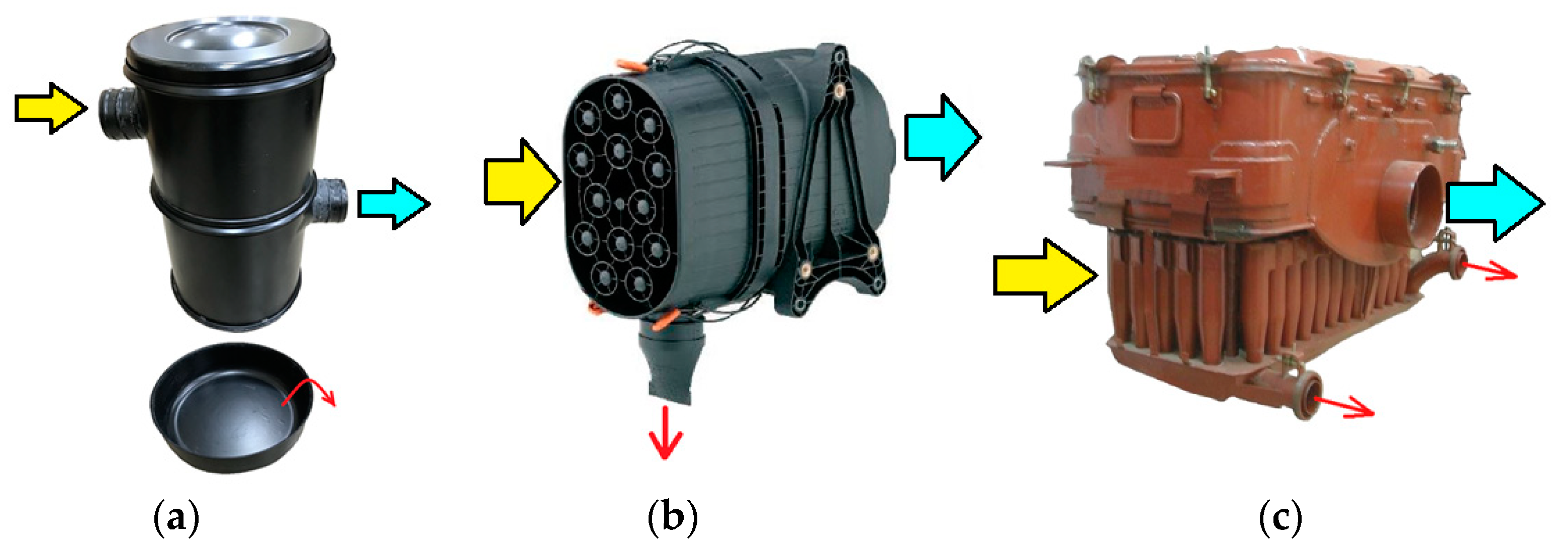
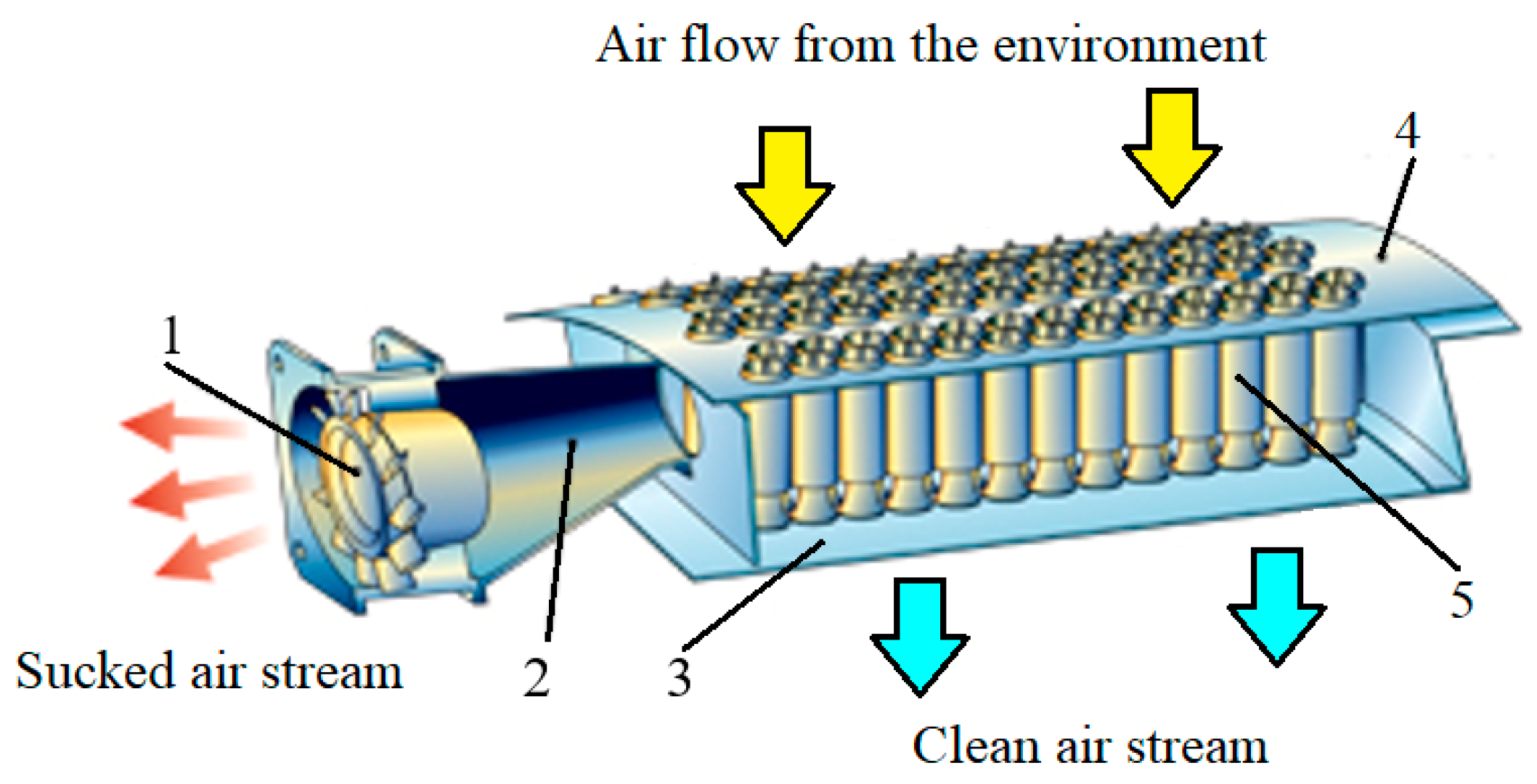
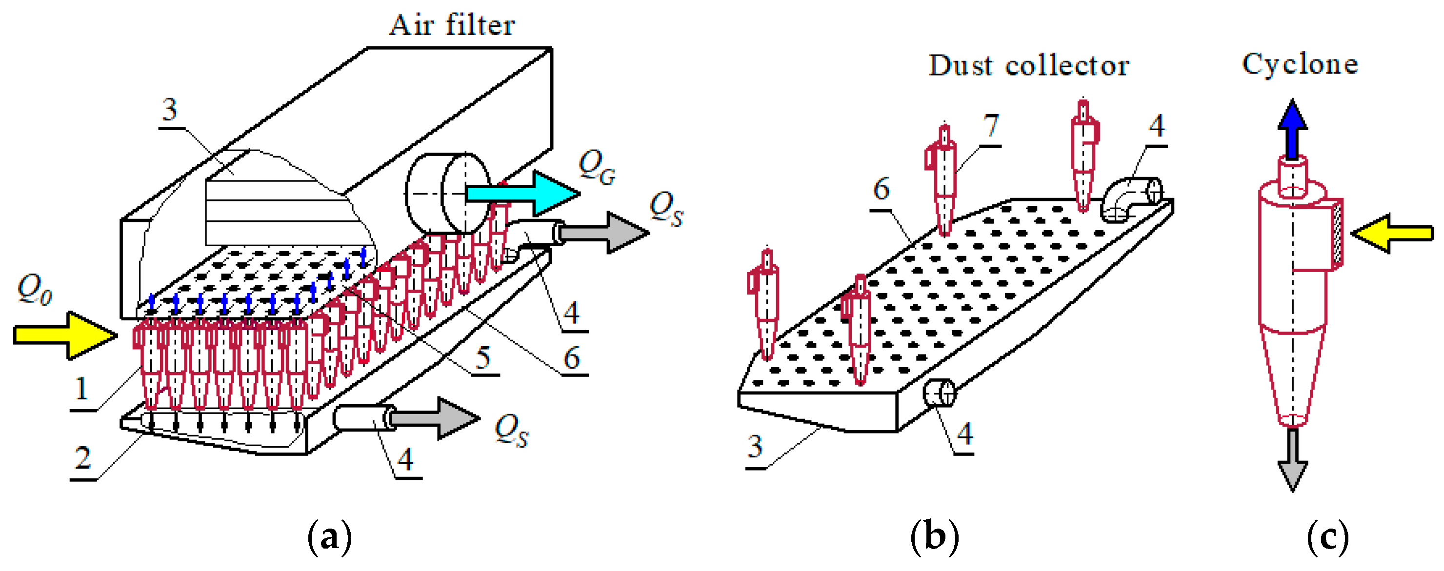
Table 1.
Dust concentrations under various air conditions.
| Author | Environmental Conditions | Value [g/m3] |
|---|---|---|
| [6,7] | Clean village environments | from 0.00001 |
| Tracked vehicles’ column movement under desert conditions | about 20 | |
| [8] | Dusty environments | 0.001–10 |
| [9] | A few meters from the sandy road on which all-terrain vehicles were moving | 0.05–10 |
| [10] | On highways | 0.0004–0.1 |
| [10] | Driving vehicles’ columns on sandy terrain | 0.03–8 |
| [11] | During helicopter take-off or landing on an accidental landing site at the height of the helicopter’s propeller end—0.5 m above the ground | 3.33 |
| [6,8,9] | At the inlet to the intake system of vehicle internal combustion engine | no more than 2.5 |
| [12] | Limited visibility | 0.6–0.7 |
| Zero visibility | about 1.5 |
Table 2.
Cellulose filter medium parameters.
| Parameters | Value |
|---|---|
| Permeability qp (m3/m2/h) at 200 Pa | 3015 |
| Basis weight gm (g/m2) | 121 |
| Thickness gt (µm) | 610 |
| Por average diameter (µm) | 76 |
Publisher’s Note: MDPI stays neutral with regard to jurisdictional claims in published maps and institutional affiliations. |
© 2021 by the author. Licensee MDPI, Basel, Switzerland. This article is an open access article distributed under the terms and conditions of the Creative Commons Attribution (CC BY) license (https://creativecommons.org/licenses/by/4.0/).
Share and Cite
MDPI and ACS Style
Dziubak, T. Experimental Studies of Dust Suction Irregularity from Multi-Cyclone Dust Collector of Two-Stage Air Filter. Energies 2021, 14, 3577. https://0-doi-org.brum.beds.ac.uk/10.3390/en14123577
AMA Style
Dziubak T. Experimental Studies of Dust Suction Irregularity from Multi-Cyclone Dust Collector of Two-Stage Air Filter. Energies. 2021; 14(12):3577. https://0-doi-org.brum.beds.ac.uk/10.3390/en14123577
Chicago/Turabian StyleDziubak, Tadeusz. 2021. "Experimental Studies of Dust Suction Irregularity from Multi-Cyclone Dust Collector of Two-Stage Air Filter" Energies 14, no. 12: 3577. https://0-doi-org.brum.beds.ac.uk/10.3390/en14123577
Note that from the first issue of 2016, this journal uses article numbers instead of page numbers. See further details here.