
A Comprehensive Review on the Recent Development of Ammonia as a Renewable Energy Carrier

 , , ,
, , ,  ,
,
Abstract
:1. Introduction
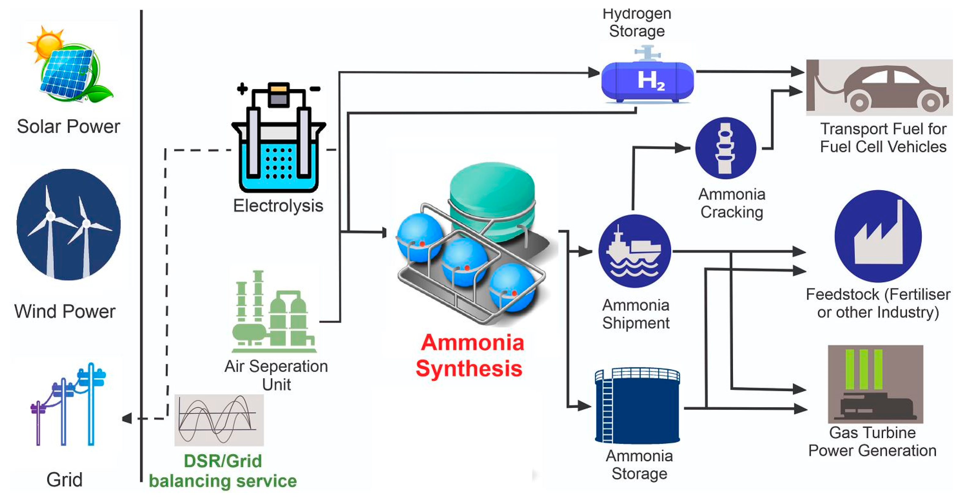
2. Key-Driver of Ammonia Economy
3. Ammonia-Based Energy Storage
3.1. Characteristics
3.2. Ammonia production Using Haber–Bosch Method
3.3. Electrically-Driven Haber–Bosch Process
4. Innovative Approaches for Ammonia Synthesis
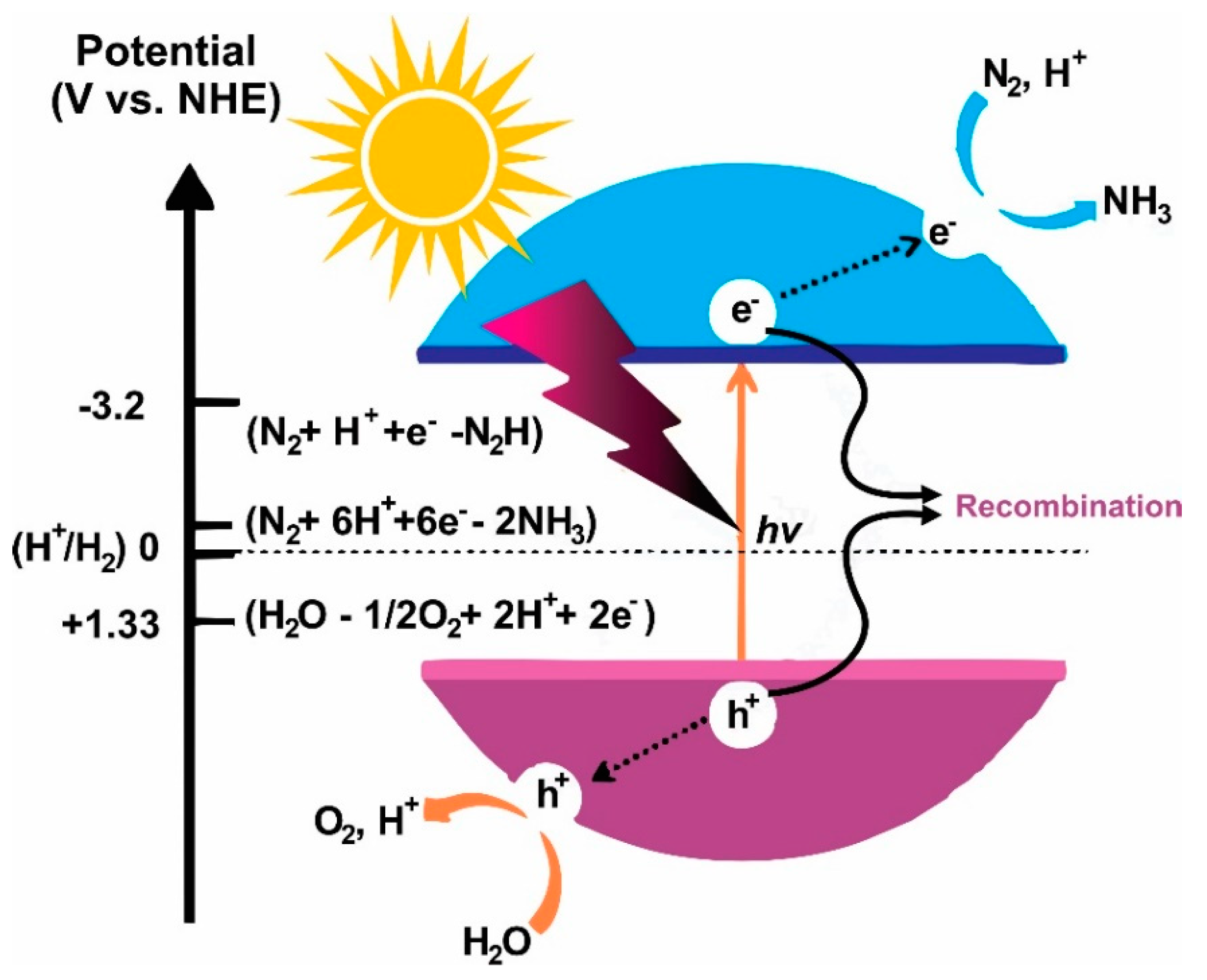
4.1. Photocatalysis
4.2. Electrocatalysis
4.3. Plasmacatalysis
5. Ammonia as a Renewable Fuel
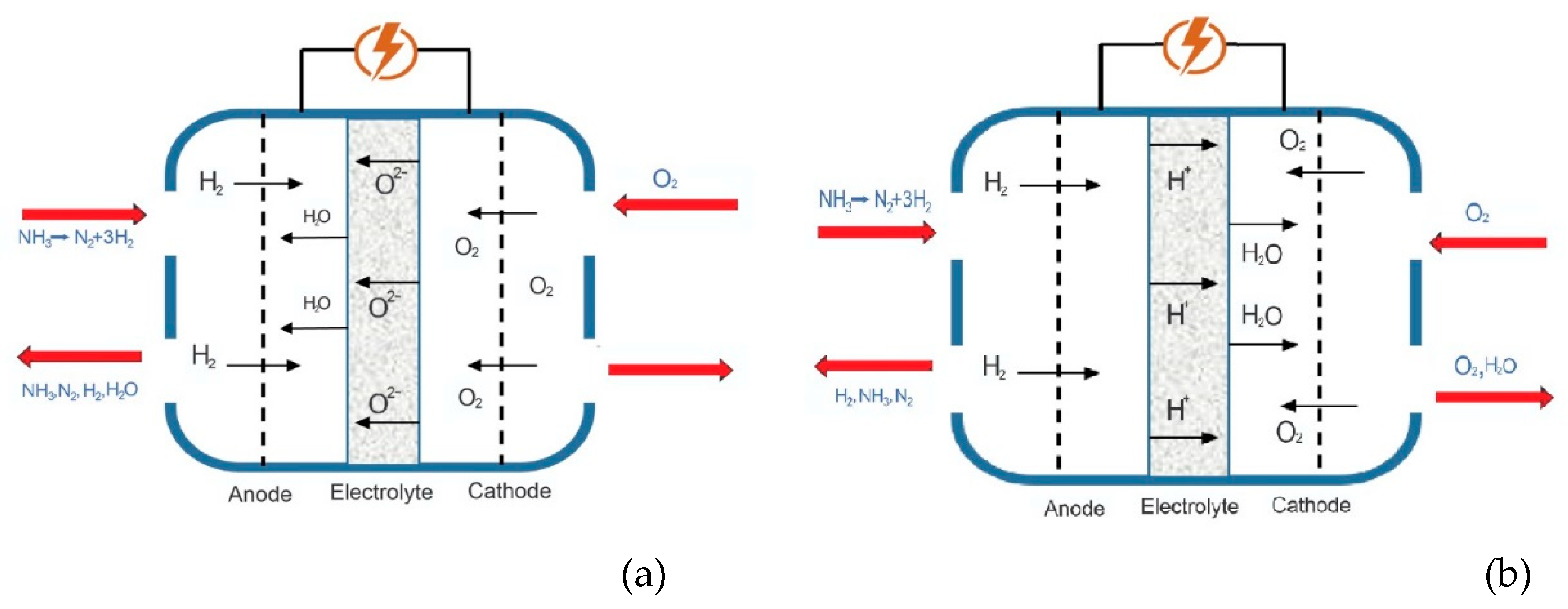
5.1. Direct Fuel Cell
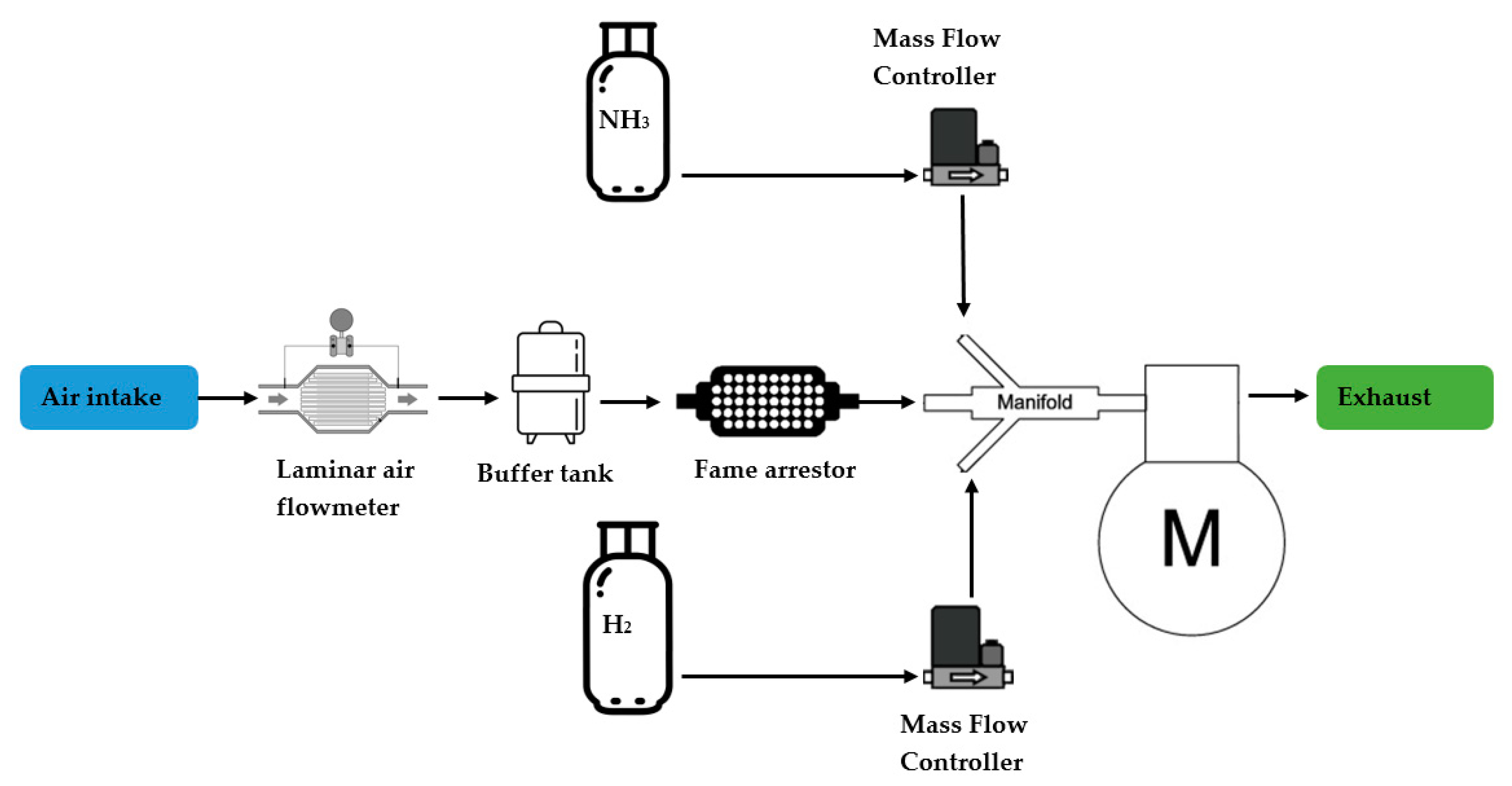
5.2. IC Engine
5.3. Gas Turbine
6. Conclusions
Author Contributions
Funding
Acknowledgments
Conflicts of Interest
References
- Cavicchioli, R.; Ripple, W.J.; Timmis, K.N.; Azam, F.; Bakken, L.R.; Baylis, M.; Behrenfeld, M.J.; Boetius, A.; Boyd, P.W.; Classen, A.T. Scientists’ warning to humanity: Microorganisms and climate change. Nat. Rev. Microbiol. 2019, 17, 569–586. [Google Scholar] [CrossRef] [PubMed] [Green Version]
- Edenhofer, O. Climate Change 2014: Mitigation of Climate Change; Cambridge University Press: Cambridge, UK, 2015; Volume 3. [Google Scholar]
- Lüthi, D.; Le Floch, M.; Bereiter, B.; Blunier, T.; Barnola, J.-M.; Siegenthaler, U.; Raynaud, D.; Jouzel, J.; Fischer, H.; Kawamura, K. High-resolution carbon dioxide concentration record 650,000–800,000 years before present. Nature 2008, 453, 379–382. [Google Scholar] [CrossRef] [PubMed]
- Pachauri, R.K.; Allen, M.R.; Barros, V.R.; Broome, J.; Cramer, W.; Christ, R.; Church, J.A.; Clarke, L.; Dahe, Q.; Dasgupta, P. Climate Change 2014: Synthesis Report. Contribution of Working Groups I, II and III to the Fifth Assessment Report of the Intergovernmental Panel on Climate Change; IPCC: Geneva, Switzerland, 2014. [Google Scholar]
- United Nations Framework Convention on Climate Change. 1992. Available online: https://unfccc.int/files/essential_background/background_publications_htmlpdf/application/pdf/conveng.pdf (accessed on 13 January 2021).
- Olivier, G.J.; Peters, J.A. Trends In Global CO2 and Total Greenhouse Gas Emissions: 2017 Report; PBL Netherlands Environmental Assessment Agency: The Hague, The Netherland, 2017. [Google Scholar]
- Jiang, X.; Guan, D. The global CO2 emissions growth after international crisis and the role of international trade. Energy Policy 2017, 109, 734–746. [Google Scholar] [CrossRef] [Green Version]
- Protocol, K. United Nations framework convention on climate change. Kyoto Protoc. 1997, 19. Available online: https://unfccc.int/kyoto_protocol (accessed on 18 January 2021).
- International Cooperation on Climate Change; United Nations Framework Convention on Climate Change (UNFCCC). Available online: https://www.dfat.gov.au/international-relations/themes/climate-change/Pages/international-cooperation-on-climate-change (accessed on 19 May 2020).
- Appl, M. The Haber-Bosch heritage: The ammonia production technology. In Proceedings of the 50th Anniversary of the IFA Technical Conference, Seville, Spain, 25–26 September 1997. [Google Scholar]
- Klein, D.; Carazo, M.P.; Doelle, M.; Bulmer, J.; Higham, A. The Paris Agreement on Climate Change: Analysis and Commentary; Oxford University Press: Oxford, UK, 2017. [Google Scholar]
- Myllyvirta, L. Analysis: Coronavirus Temporarily Reduced China’s CO2 Emissions by a Quarter; Carbon Brief. 2020. Available online: https://www.carbonbrief.org/analysis-coronavirus-has-temporarily-reduced-chinas-co2-emissions-by-a-quarter (accessed on 8 January 2021).
- Zhang, R.; Zhang, Y.; Lin, H.; Feng, X.; Fu, T.-M.; Wang, Y. NOx Emission Reduction and Recovery during COVID-19 in East China. Atmosphere 2020, 11, 433. [Google Scholar] [CrossRef] [Green Version]
- Viswanathan, B. Chapter 9—Hydrogen as an Energy Carrier. In Energy Sources; Viswanathan, B., Ed.; Elsevier: Amsterdam, The Netherlands, 2017; pp. 161–183. [Google Scholar]
- Edwards, P.; Kuznetsov, V.; David, W. Hydrogen energy. Philos. Trans. R. Soc. A Math. Phys. Eng. Sci. 2007, 365, 1043–1056. [Google Scholar] [CrossRef]
- Valera-Medina, A.; Xiao, H.; Owen-Jones, M.; David, W.I.; Bowen, P.J. Ammonia for power. Prog. Energy Combust. Sci. 2018, 69, 63–102. [Google Scholar] [CrossRef]
- Paris 2015: Tracking Country Climate Pledges. 2017. Available online: https://www.carbonbrief.org/paris-2015-tracking-country-climate-pledges (accessed on 24 June 2020).
- Innovation Promotion Program Energy Carriers. SIP 2016. Available online: https://www8.cao.go.jp/cstp/panhu/sip_english/20-23.pdf (accessed on 8 January 2021).
- Crolius, S.H. Ammonia Included in Japan’s International Resource Strategy. 2020. Available online: https://www.ammoniaenergy.org/articles/ammonia-included-in-japans-international-resource-strategy/ (accessed on 18 May 2020).
- Brown, T. Green Ammonia Plants Win Financing in Australia and New Zealand. 2020. Available online: https://www.ammoniaenergy.org/articles/green-ammonia-plants-win-financing-in-australia-and-new-zealand/ (accessed on 19 May 2020).
- Service, R.F. Ammonia—A Renewable Fuel Made From Sun, Air, and Water—Could Power the Globe Without Carbon. 2018. Available online: https://www.sciencemag.org/news/2018/07/ammonia-renewable-fuel-made-sun-air-and-water-could-power-globe-without-carbon# (accessed on 17 May 2020).
- Pattabathula, V.; Richardson, J. Introduction to Ammonia Production. 2016. Available online: https://www.aiche.org/resources/publications/cep/2016/september/introduction-ammonia-production (accessed on 15 May 2020).
- Nitrogen Statistics and Information. 2020. Available online: https://www.usgs.gov/centers/nmic/nitrogen-statistics-and-information (accessed on 20 May 2021).
- Mineral. Commodity Summaries. 2020. Available online: https://pubs.usgs.gov/periodicals/mcs2020/mcs2020,pdf (accessed on 18 June 2020).
- Egenhofer, C.; Schrefler, L.; Rizos, V.; Marcu, A.; Genoese, F.; Renda, A.; Wieczorkiewicz, J.; Roth, S.; Infelise, F.; Luchetta, G. The Composition and Drivers of Energy Prices and Costs in Energy-Intensive Industries: The Case of Ceramics, Glass and Chemicals. 2014. Available online: http://aei.pitt.edu/50255/1/CEPS_Energy_Prices_Study_Consolidated_version.pdf (accessed on 14 January 2021).
- Patil, B.; Wang, Q.; Hessel, V.; Lang, J. Plasma N2-fixation: 1900–2014. Catal. Today 2015, 256, 49–66. [Google Scholar] [CrossRef]
- Afif, A.; Radenahmad, N.; Cheok, Q.; Shams, S.; Kim, J.H.; Azad, A.K. Ammonia-fed fuel cells: A comprehensive review. Renew. Sustain. Energy Rev. 2016, 60, 822–835. [Google Scholar] [CrossRef]
- Davis, B.L.; Dixon, D.A.; Garner, E.B.; Gordon, J.C.; Matus, M.H.; Scott, B.; Stephens, F.H. Efficient regeneration of partially spent ammonia borane fuel. Angew. Chem. Int. Ed. 2009, 48, 6812–6816. [Google Scholar] [CrossRef]
- Leigh, G. Haber-Bosch and Other Industrial Processes. In Catalysts for Nitrogen Fixation; Springer: Dordrecht, The Netherlands, 2004; pp. 33–54. [Google Scholar] [CrossRef]
- Boerner, L.K. Industrial ammonia production emits more CO2 than any other chemical-making reaction. Chem. Eng. News 2019, 97. Available online: https://0-cen-acs-org.brum.beds.ac.uk/environment/green-chemistry/Industrial-ammonia-production-emits-CO2/97/i24#:~:text=It%20belched%20up%20to%20about,reaction%20(see%20page%2023) (accessed on 12 February 2021).
- Snoeckx, R.; Bogaerts, A. Plasma technology–a novel solution for CO 2 conversion? Chem. Soc. Rev. 2017, 46, 5805–5863. [Google Scholar] [CrossRef] [Green Version]
- MacFarlane, D.R.; Choi, J.; Suryanto, B.H.; Jalili, R.; Chatti, M.; Azofra, L.M.; Simonov, A.N. Liquefied sunshine: Transforming renewables into fertilizers and energy carriers with electromaterials. Adv. Mater. 2020, 32, 1904804. [Google Scholar] [CrossRef]
- Yan, Z.; Ji, M.; Xia, J.; Zhu, H. Recent Advanced Materials for Electrochemical and Photoelectrochemical Synthesis of Ammonia from Dinitrogen: One Step Closer to a Sustainable Energy Future. Adv. Energy Mater. 2020, 10, 1902020. [Google Scholar] [CrossRef]
- Xu, H.; Ithisuphalap, K.; Li, Y.; Mukherjee, S.; Lattimer, J.; Soloveichik, G.; Wu, G. Electrochemical Ammonia Synthesis through N2 and H2O under Ambient Conditions: Theory, Practices, and Challenges for Catalysts and Electrolytes. Nano Energy 2020, 69, 104469. [Google Scholar] [CrossRef]
- MacFarlane, D.R.; Cherepanov, P.V.; Choi, J.; Suryanto, B.H.R.; Hodgetts, R.Y.; Bakker, J.M.; Vallana, F.M.F.; Simonov, A.N. A Roadmap to the Ammonia Economy. Joule 2020, 4, 1186–1205. [Google Scholar] [CrossRef]
- Wang, L.; Xia, M.; Wang, H.; Huang, K.; Qian, C.; Maravelias, C.T.; Ozin, G.A. Greening ammonia toward the solar ammonia refinery. Joule 2018, 2, 1055–1074. [Google Scholar] [CrossRef] [Green Version]
- Lan, R.; Irvine, J.T.; Tao, S. Ammonia and related chemicals as potential indirect hydrogen storage materials. Int. J. Hydrog. Energy 2012, 37, 1482–1494. [Google Scholar] [CrossRef]
- Kojima, Y. High Purity Hydrogen Generation from Ammonia. 2017. Available online: https://ep70.eventpilotadmin.com/web/page.php?page=IntHtml&project=ACS17FALL&id=2747276 (accessed on 22 January 2021).
- Makepeace, J.W.; He, T.; Weidenthaler, C.; Jensen, T.R.; Chang, F.; Vegge, T.; Ngene, P.; Kojima, Y.; de Jongh, P.E.; Chen, P. Reversible ammonia-based and liquid organic hydrogen carriers for high-density hydrogen storage: Recent progress. Int. J. Hydrog. Energy 2019, 44, 7746–7767. [Google Scholar] [CrossRef]
- Bartels, R.J.; Pate, M.B.; Olson, N.K. An economic survey of hydrogen production from conventional and alternative energy sources. Int. J. Hydrog. Energy 2010, 35, 8371–8384. [Google Scholar] [CrossRef]
- Schultz, K.R. Use of the Modular Helium Reactor for Hydrogen Production; General Atomics (US): San Diego, CA, USA, 2003. Available online: https://www.osti.gov/biblio/821808-use-modular-helium-reactor-hydrogen-production (accessed on 3 February 2021).
- Orhan, M.F.; Dincer, I.; Naterer, G.F. Cost analysis of a thermochemical Cu–Cl pilot plant for nuclear-based hydrogen production. Int. J. Hydrog. Energy 2008, 33, 6006–6020. [Google Scholar] [CrossRef]
- Charvin, P.; Stéphane, A.; Florent, L.; Gilles, F. Analysis of solar chemical processes for hydrogen production from water splitting thermochemical cycles. Energy Convers. Manag. 2008, 49, 1547–1556. [Google Scholar] [CrossRef]
- Bartels, J.R. A Feasibility Study of Implementing an Ammonia Economy. Master’s Theses, Iowa State University, Iowa, IA, USA, 2008. [Google Scholar]
- Andersson, J.; Grönkvist, S. Large-scale storage of hydrogen. Int. J. Hydrog. Energy 2019, 44, 11901–11919. [Google Scholar] [CrossRef]
- Anhydrous Ammonia Transportation Information. 2007. Available online: http://www.mda.state.mn.us/chemicals/spills/ammoniaspills/transportation.htm (accessed on 15 June 2020).
- Paster, M. Hydrogen Deliver Options and Issues. Available online: http://www1.eere.energy.gov/hydrogenandfuelcells/analysis/pdfs/paster_h2_delivery.pdf (accessed on 15 June 2020).
- Appl, M. Ammonia: Principles and Industrial Practice; Vch Verlagsgesellschaft Mbh: Weinheim, Germany, 1999. Available online: https://trove.nla.gov.au/work/32581098 (accessed on 15 June 2020).
- Christensen, C.H.; Johannessen, T.; Sørensen, R.Z.; Nørskov, J.K. Towards an ammonia-mediated hydrogen economy? Catal. Today 2006, 111, 140–144. [Google Scholar] [CrossRef]
- Christensen, C.H.; Sørensen, R.Z.; Johannessen, T.; Quaade, U.J.; Honkala, K.; Elmøe, T.D.; Køhler, R.; Nørskov, J.K. Metal ammine complexes for hydrogen storage. J. Mater. Chem. 2005, 15, 4106–4108. [Google Scholar] [CrossRef]
- Haynes, W.M. CRC Handbook of Chemistry and Physics; CRC Press: Boca Raton, FL, USA, 2014. [Google Scholar]
- Karabeyoglu, A.; Evans, B. Fuel conditioning system for ammonia fired power plants. In Proceedings of the NH3 Congress, Ames, IA, USA, 1 October 2012; Available online: https://www.ammoniaenergy.org/wp-content/uploads/2021/01/evans-brian.pdf (accessed on 23 January 2021).
- Cole-Parmer Instrument Company. Chemical Compatibility Database, Ammonia, Anhydrous. 2017. Available online: https://www.coleparmer.co.uk/chemical-resistance (accessed on 10 June 2021).
- Pincha, M.E.; Heizer, B.L.; McHale, M.P. Material Compatibility Problems for Ammonia Systems; SAE Technical Paper: Washington, DC, USA, 1988. [Google Scholar]
- Graco, Chemical Compatibility Guide. 2013. Available online: https://www.graco.com/content/dam/graco/ipd/literature/misc/chemical-compatibility-guide/Graco_ChemCompGuideEN-B.pdf (accessed on 9 June 2021).
- CDC. Ammonia. Available online: https://www.cdc.gov/niosh/idlh/7664417 (accessed on 26 May 2020).
- Ravishankara, A.; Daniel, J.S.; Portmann, R.W. Nitrous oxide (N2O): The dominant ozone-depleting substance emitted in the 21st century. Science 2009, 326, 123–125. [Google Scholar] [CrossRef] [Green Version]
- Klerke, A.; Christensen, C.H.; Nørskov, J.K.; Vegge, T. Ammonia for hydrogen storage: Challenges and opportunities. J. Mater. Chem. 2008, 18, 2304–2310. [Google Scholar] [CrossRef]
- Organization, W.H. Ammonia Health and Safety Guide-Health and Safety Guide 37; International Programme on Chemical Safety: Geneva, Switzerland, 1990. [Google Scholar]
- Ryer-Powder, J.E. Health effects of ammonia. Plant/Oper. Prog. 1991, 10, 228–232. [Google Scholar] [CrossRef]
- Smith, C.; Hill, A.K.; Torrente-Murciano, L. Current and future role of Haber-Bosch ammonia in a carbon-free energy landscape. Energy Environ. Sci. 2020, 13, 331–344. [Google Scholar] [CrossRef]
- Wilkinson, I. Green Ammonia. 2017. Available online: Siemens.com (accessed on 23 January 2021).
- Schmuecker, J. Schmuecker Pinehurst Farm, l.L.C. Available online: http://solarhydrogensystem.com/ (accessed on 16 June 2020).
- Cholteeva, Y. Sable Chemicals and Tatanga Energy to Construct Solar Energy Plant in Zimbabwe. Available online: https://www.power-technology.com/news/sable-chemicals-and-tatanga-energy-to-construct-solar-energy-plant-in-zimbabwe/ (accessed on 18 June 2020).
- Solar Ammonia. 2017. Available online: https://www.yara.com/ (accessed on 13 June 2020).
- Brown, T. Renewable Ammonia Demonstration Plant Announced in South Australia. 2018. Available online: https://ammoniaindustry.com/renewable-ammonia-demonstration-plant-announced-in-south-australia/ (accessed on 14 June 2020).
- Rusanov, V.D.; Fridman, A.A.; Sholin, G.V. The physics of a chemically active plasma with nonequilibrium vibrational excitation of molecules. Sov. Phys. Uspekhi 1981, 24, 447. [Google Scholar] [CrossRef]
- Chen, X.; Li, N.; Kong, Z.; Ong, W.-J.; Zhao, X. Photocatalytic fixation of nitrogen to ammonia: State-of-the-art advancements and future prospects. Mater. Horiz. 2018, 5, 9–27. [Google Scholar] [CrossRef]
- Schrauzer, G.; Guth, T. Photolysis of water and photoreduction of nitrogen on titanium dioxide. J. Am. Chem. Soc. 2002, 99, 7189–7193. [Google Scholar] [CrossRef]
- Bourgeois, S.; Diakite, D.; Perdereau, M. A study of TiO2 powders as a support for the photochemical synthesis of ammonia. React. Solids 1988, 6, 95–104. [Google Scholar] [CrossRef]
- Hirakawa, H.; Hashimoto, M.; Shiraishi, Y.; Hirai, T. Photocatalytic conversion of nitrogen to ammonia with water on surface oxygen vacancies of titanium dioxide. J. Am. Chem. Soc. 2017, 139, 10929–10936. [Google Scholar] [CrossRef] [PubMed]
- Ranjit, K.T.; Varadarajan, T.K.; Viswanathan, B. Photocatalytic reduction of dinitrogen to ammonia over noble-metal-loaded TiO2. J. Photochem. Photobiol. A Chem. 1996, 96, 181–185. [Google Scholar] [CrossRef]
- Lashgari, M.; Zeinalkhani, P. Photocatalytic N2 conversion to ammonia using efficient nanostructured solar-energy-materials in aqueous media: A novel hydrogenation strategy and basic understanding of the phenomenon. Appl. Catal. A Gen. 2017, 529, 91–97. [Google Scholar] [CrossRef]
- Sun, S.; An, Q.; Wang, W.; Zhang, L.; Liu, J.; Goddard, W.A., III. Efficient photocatalytic reduction of dinitrogen to ammonia on bismuth monoxide quantum dots. J. Mater. Chem. A 2017, 5, 201–209. [Google Scholar] [CrossRef] [Green Version]
- Hu, S.; Chen, X.; Li, Q.; Zhao, Y.; Mao, W. Effect of sulfur vacancies on the nitrogen photofixation performance of ternary metal sulfide photocatalysts. Catal. Sci. Technol. 2016, 6, 5884–5890. [Google Scholar] [CrossRef]
- Ye, L.; Han, C.; Ma, Z.; Leng, Y.; Li, J.; Ji, X.; Bi, D.; Xie, H.; Huang, Z. Ni2P loading on Cd0.5Zn0.5S solid solution for exceptional photocatalytic nitrogen fixation under visible light. Chem. Eng. J. 2017, 307, 311–318. [Google Scholar] [CrossRef]
- Wei, P.; Yang, Q.; Guo, L. Bismuth oxyhalide compounds as photocatalysts. Prog. Chem. 2009, 21, 1734–1741. [Google Scholar]
- Dong, G.; Ho, W.; Wang, C. Selective photocatalytic N2 fixation dependent on gC3N4 induced by nitrogen vacancies. J. Mater. Chem. A 2015, 3, 23435–23441. [Google Scholar] [CrossRef]
- Hu, S.; Chen, X.; Li, Q.; Li, F.; Fan, Z.; Wang, H.; Wang, Y.; Zheng, B.; Wu, G. Fe3+ doping promoted N2 photofixation ability of honeycombed graphitic carbon nitride: The experimental and density functional theory simulation analysis. Appl. Catal. B Environ. 2017, 201, 58–69. [Google Scholar] [CrossRef]
- Ileperuma, O.A.; Tennakone, K.; Dissanayake, W.D.D.P. Photocatalytic behaviour of metal doped titanium dioxide: Studies on the photochemical synthesis of ammonia on Mg/TiO2 catalyst systems. Appl. Catal. 1990, 62, L1–L5. [Google Scholar] [CrossRef]
- Soria, J.; Conesa, J.; Augugliaro, V.; Palmisano, L.; Schiavello, M.; Sclafani, A. Dinitrogen photoreduction to ammonia over titanium dioxide powders doped with ferric ions. J. Phys. Chem. 1991, 95, 274–282. [Google Scholar] [CrossRef]
- Ileperuma, O.A.; Thaminimulla, C.T.K.; Kiridena, W.C.B. Photoreduction of N2 to NH3 and H2O to H2 on metal doped TiO2 catalysts (M = Ce, V). Sol. Eergy Mater. Sol. Cells 1993, 28, 335–343. [Google Scholar] [CrossRef]
- Zhao, W.; Zhang, J.; Zhu, X.; Zhang, M.; Tang, J.; Tan, M.; Wang, Y. Enhanced nitrogen photofixation on Fe-doped TiO2 with highly exposed (1, 0 1) facets in the presence of ethanol as scavenger. Appl. Catal. B Environ. 2014, 144, 468–477. [Google Scholar] [CrossRef]
- Janet, C.; Navaladian, S.; Viswanathan, B.; Varadarajan, T.; Viswanath, R. Heterogeneous wet chemical synthesis of superlattice-type hierarchical ZnO architectures for concurrent H2 production and N2 reduction. J. Phys. Chem. C 2010, 114, 2622–2632. [Google Scholar] [CrossRef]
- Khader, M.M.; Lichtin, N.N.; Vurens, G.H.; Salmeron, M.; Somorjai, G.A. Photoassisted catalytic dissociation of water and reduction of nitrogen to ammonia on partially reduced ferric oxide. Langmuir 1987, 3, 303–304. [Google Scholar] [CrossRef]
- Hao, Y.; Dong, X.; Zhai, S.; Ma, H.; Wang, X.; Zhang, X. Hydrogenated bismuth molybdate nanoframe for efficient sunlight-driven nitrogen fixation from air. Chem.–A Eur. J. 2016, 22, 18722–18728. [Google Scholar] [CrossRef]
- Miyama, H.; Fujii, N.; Nagae, Y. Heterogeneous photocatalytic synthesis of ammonia from water and nitrogen. Chem. Phys. Lett. 1980, 74, 523–524. [Google Scholar] [CrossRef]
- Khan, T.M.M.; Bhardwaj, R.C.; Bhardwaj, C. Catalytic Fixation of Nitrogen by the Photocatalytic CdS/Pt/RuO2 Particulate System in the Presence of Aqueous [Ru (Hedta) N2]⊖ Complex. Angew. Chem. Int. Ed. Engl. 1988, 27, 923–925. [Google Scholar] [CrossRef]
- Sun, S.; Li, X.; Wang, W.; Zhang, L.; Sun, X. Photocatalytic robust solar energy reduction of dinitrogen to ammonia on ultrathin MoS2. Appl. Catal. B Environ. 2017, 200, 323–329. [Google Scholar] [CrossRef] [Green Version]
- Cao, Y.; Hu, S.; Li, F.; Fan, Z.; Bai, J.; Lu, G.; Wang, Q. Photofixation of atmospheric nitrogen to ammonia with a novel ternary metal sulfide catalyst under visible light. RSC Adv. 2016, 6, 49862–49867. [Google Scholar] [CrossRef]
- Zhang, Q.; Hu, S.; Fan, Z.; Liu, D.; Zhao, Y.; Ma, H.; Li, F. Preparation of gC3N4/ZnMoCdS hybrid heterojunction catalyst with outstanding nitrogen photofixation performance under visible light via hydrothermal post-treatment. Dalton Trans. 2016, 45, 3497–3505. [Google Scholar] [CrossRef] [PubMed]
- Hu, S.; Li, Y.; Li, F.; Fan, Z.; Ma, H.; Li, W.; Kang, X. Construction of g-C3N4/Zn0.11Sn0.12Cd0.88S1.12 hybrid heterojunction catalyst with outstanding nitrogen photofixation performance induced by sulfur vacancies. ACS Sustain. Chem. Eng. 2016, 4, 2269–2278. [Google Scholar] [CrossRef]
- Bai, Y.; Ye, L.; Chen, T.; Wang, L.; Shi, X.; Zhang, X.; Chen, D. Facet-dependent photocatalytic N2 fixation of bismuth-rich Bi5O7I nanosheets. ACS Appl. Mater. Interfaces 2016, 8, 27661–27668. [Google Scholar] [CrossRef]
- Li, H.; Shang, J.; Shi, J.; Zhao, K.; Zhang, L. Facet-dependent solar ammonia synthesis of BiOCl nanosheets via a proton-assisted electron transfer pathway. Nanoscale 2016, 8, 1986–1993. [Google Scholar] [CrossRef]
- Li, H.; Shang, J.; Ai, Z.; Zhang, L. Efficient visible light nitrogen fixation with BiOBr nanosheets of oxygen vacancies on the exposed facets. J. Am. Chem. Soc. 2015, 137, 6393–6399. [Google Scholar] [CrossRef]
- Wang, S.; Hai, X.; Ding, X.; Chang, K.; Xiang, Y.; Meng, X.; Yang, Z.; Chen, H.; Ye, J. Light-Switchable Oxygen Vacancies in Ultrafine Bi5O7Br Nanotubes for Boosting Solar-Driven Nitrogen Fixation in Pure Water. Adv. Mater. 2017, 29, 1701774. [Google Scholar] [CrossRef]
- Wang, Y.; Wei, W.; Li, M.; Hu, S.; Zhang, J.; Feng, R. In situ construction of Z-scheme gC3N4/Mg 1.1Al0.3Fe 0.2O1.7 nanorod heterostructures with high N2 photofixation ability under visible light. RSC Adv. 2017, 7, 18099–18107. [Google Scholar] [CrossRef] [Green Version]
- Hu, S.; Zhang, W.; Bai, J.; Lu, G.; Zhang, L.; Wu, G. Construction of a 2D/2D gC3N4/rGO hybrid heterojunction catalyst with outstanding charge separation ability and nitrogen photofixation performance via a surface protonation process. RSC Adv. 2016, 6, 25695–25702. [Google Scholar] [CrossRef]
- Cao, S.; Zhou, N.; Gao, F.; Chen, H.; Jiang, F. All-solid-state Z-scheme 3, 4-dihydroxybenzaldehyde-functionalized Ga2O3/graphitic carbon nitride photocatalyst with aromatic rings as electron mediators for visible-light photocatalytic nitrogen fixation. Appl. Catal. B Environ. 2017, 218, 600–610. [Google Scholar] [CrossRef]
- Liang, H.; Zou, H.; Hu, S. Preparation of the W 18 O49/gC3N4 heterojunction catalyst with full-spectrum-driven photocatalytic N 2 photofixation ability from the UV to near infrared region. New J. Chem. 2017, 41, 8920–8926. [Google Scholar] [CrossRef]
- Cong, L.; Yu, Z.; Liu, F.; Huang, W. Electrochemical synthesis of ammonia from N2 and H2O using a typical non-noble metal carbon-based catalyst under ambient conditions. Catal. Sci. Technol. 2019, 9, 1208–1214. [Google Scholar] [CrossRef]
- Kyriakou, V.; Garagounis, I.; Vasileiou, E.; Vourros, A.; Stoukides, M. Progress in the electrochemical synthesis of ammonia. Catal. Today 2017, 286, 2–13. [Google Scholar] [CrossRef]
- Garagounis, I.; Vourros, A.; Stoukides, D.; Dasopoulos, D.; Stoukides, M. Electrochemical Synthesis of Ammonia: Recent Efforts and Future Outlook. Membranes 2019, 9, 112. [Google Scholar] [CrossRef] [Green Version]
- Wang, B.H.; de Wang, J.; Liu, R.; Xie, Y.H.; Li, Z.J. Synthesis of ammonia from natural gas at atmospheric pressure with doped ceria–Ca3(PO 4)2–K3 PO4 composite electrolyte and its proton conductivity at intermediate temperature. J. Solid State Electrochem. 2007, 11, 27–31. [Google Scholar] [CrossRef]
- Wang, B.; Liu, R.; Wang, J.; Li, Z.; Xie, Y. Doped ceria-Ca-3 (PO4) 2-K3PO4 composite electrolyte: Proton conductivity at intermediate temperature and application in atmospheric pressure ammonia synthesis. Chin. J. Inorg. Chem. 2005, 21, 1551–1555. [Google Scholar]
- Skodra, A.; Stoukides, M. Electrocatalytic synthesis of ammonia from steam and nitrogen at atmospheric pressure. Solid State Ion. 2009, 180, 1332–1336. [Google Scholar] [CrossRef]
- Jeoung, H.; Kim, J.N.; Yoo, C.-Y.; Joo, J.H.; Yu, J.H.; Song, K.C.; Sharma, M.; Yoon, H.C. Electrochemical synthesis of ammonia from water and nitrogen using a Pt/GDC/Pt cell. Korean Chem. Eng. Res. 2014, 52, 58–62. [Google Scholar] [CrossRef] [Green Version]
- Murakami, T.; Nishikiori, T.; Nohira, T.; Ito, Y. Electrolytic synthesis of ammonia in molten salts under atmospheric pressure. J. Am. Chem. Soc. 2003, 125, 334–335. [Google Scholar] [CrossRef]
- Murakami, T.; Nohira, T.; Goto, T.; Ogata, Y.H.; Ito, Y. Electrolytic ammonia synthesis from water and nitrogen gas in molten salt under atmospheric pressure. Electrochim. Acta 2005, 50, 5423–5426. [Google Scholar] [CrossRef]
- Murakami, T.; Nohira, T.; Araki, Y.; Goto, T.; Hagiwara, R.; Ogata, Y.H. Electrolytic Synthesis of Ammonia from Water and Nitrogen under Atmospheric Pressure Using a Boron-Doped Diamond Electrode as a Nonconsumable Anode. Electrochem. Solid State Lett. 2007, 10, E4. [Google Scholar] [CrossRef]
- Murakami, T.; Nishikiori, T.; Nohira, T.; Ito, Y. Electrolytic ammonia synthesis from hydrogen chloride and nitrogen gases with simultaneous recovery of chlorine under atmospheric pressure. Electrochem. Solid-State Lett. 2005, 8, D19–D21. [Google Scholar] [CrossRef]
- Murakami, T.; Nohira, T.; Ogata, Y.H.; Ito, Y. Electrolytic ammonia synthesis in molten salts under atmospheric pressure using methane as a hydrogen source. Electrochem. Solid-State Lett. 2005, 8, D12–D14. [Google Scholar] [CrossRef]
- Murakami, T.; Nohira, T.; Ogata, Y.H.; Ito, Y. Electrochemical synthesis of ammonia and coproduction of metal sulfides from hydrogen sulfide and nitrogen under atmospheric pressure. J. Electrochem. Soc. 2005, 152, D109–D112. [Google Scholar] [CrossRef]
- Licht, S.; Cui, B.; Wang, B.; Li, F.-F.; Lau, J.; Liu, S. Ammonia synthesis by N2 and steam electrolysis in molten hydroxide suspensions of nanoscale Fe2O3. Science 2014, 345, 637–640. [Google Scholar] [CrossRef]
- Kordali, V.; Kyriacou, G.; Lambrou, C. Electrochemical synthesis of ammonia at atmospheric pressure and low temperature in a solid polymer electrolyte cell. Chem. Commun. 2000, 17, 1673–1674. [Google Scholar] [CrossRef]
- Marnellos, G.; Stoukides, M. Ammonia synthesis at atmospheric pressure. Science 1998, 282, 98–100. [Google Scholar] [CrossRef]
- Li, Z.; Liu, R.; Xie, Y.; Feng, S.; Wang, J. A novel method for preparation of doped Ba3(Ca1.18Nb1.82)O9−δ: Application to ammonia synthesis at atmospheric pressure. Solid State Ion. 2005, 176, 1063–1066. [Google Scholar] [CrossRef]
- Li, Z.; Liu, R.; Wang, J.; Xu, Z.; Xie, Y.; Wang, B. Preparation of double-doped BaCeO3 and its application in the synthesis of ammonia at atmospheric pressure. Sci. Technol. Adv. Mater. 2007, 8, 566. [Google Scholar] [CrossRef]
- Vasileiou, E.; Kyriakou, V.; Garagounis, I.; Vourros, A.; Stoukides, M. Ammonia synthesis at atmospheric pressure in a BaCe0.2Zr0.7Y0.1O2.9 solid electrolyte cell. Solid State Ion. 2015, 275, 110–116. [Google Scholar] [CrossRef]
- Zhang, F.; Yang, Q.; Pan, B.; Xu, R.; Wang, H.; Ma, G. Proton conduction in La0.9Sr0.1Ga0.8Mg0.2O3−α ceramic prepared via microemulsion method and its application in ammonia synthesis at atmospheric pressure. Mater. Lett. 2007, 61, 4144–4148. [Google Scholar] [CrossRef]
- Wang, J.-D.; Xie, Y.-H.; Zhang, Z.-F.; Liu, R.-Q.; Li, Z.-J. Protonic conduction in Ca2+-doped La2M2O7 (M= Ce, Zr) with its application to ammonia synthesis electrochemically. Mater. Res. Bull. 2005, 40, 1294–1302. [Google Scholar] [CrossRef]
- Xie, Y.-H.; Wang, J.-D.; Liu, R.-Q.; Su, X.-T.; Sun, Z.-P.; Li, Z.-J. Preparation of La1.9Ca0.Zr2O6.95 with pyrochlore structure and its application in synthesis of ammonia at atmospheric pressure. Solid State Ion. 2004, 168, 117–121. [Google Scholar] [CrossRef]
- Li, Z.-J.; Liu, R.-Q.; Wang, J.-D.; Xie, Y.-H.; Yue, F. Preparation of BaCe0.8Gd0.2O3−δ by the citrate method and its application in the synthesis of ammonia at atmospheric pressure. J. Solid State Electrochem. 2005, 9, 201–204. [Google Scholar] [CrossRef]
- Guo, Y.; Liu, B.; Yang, Q.; Chen, C.; Wang, W.; Ma, G. Preparation via microemulsion method and proton conduction at intermediate-temperature of BaCe1−xYxO3−α. Electrochem. Commun. 2009, 11, 153–156. [Google Scholar] [CrossRef]
- Vasileiou, E.; Kyriakou, V.; Garagounis, I.; Vourros, A.; Manerbino, A.; Coors, W.; Stoukides, M. Electrochemical enhancement of ammonia synthesis in a BaZr0. 7Ce0. 2Y0. 1O2. 9 solid electrolyte cell. Solid State Ion. 2016, 288, 357–362. [Google Scholar] [CrossRef]
- Zhang, M.; Xu, J.; Ma, G. Proton conduction in BaxCe0.8Y0.2O3− α + 0.04ZnO at intermediate temperatures and its application in ammonia synthesis at atmospheric pressure. J. Mater. Sci. 2011, 46, 4690–4694. [Google Scholar] [CrossRef]
- Liu, R.-Q.; Xie, Y.-H.; Wang, J.-D.; Li, Z.-J.; Wang, B.-H. Synthesis of ammonia at atmospheric pressure with Ce0.8M0.2O2− δ (M= La, Y, Gd, Sm) and their proton conduction at intermediate temperature. Solid State Ion. 2006, 177, 73–76. [Google Scholar] [CrossRef]
- Chen, C.; Wang, W.; Ma, G. Proton conduction in La0.9M0.1cGa0.8Mg0.2O3-α at intermediate temperature and its application to synthesis of ammonia at atmospheric pressure. Acta Chim. Sin. 2009, 67, 623–628. [Google Scholar]
- Chen, C.; Ma, G. Preparation, proton conduction, and application in ammonia synthesis at atmospheric pressure of La0.9Ba0.1Ga1–xMgxO3–α. J. Mater. Sci. 2008, 43, 5109–5114. [Google Scholar] [CrossRef]
- Chen, C.; Ma, G. Proton conduction in BaCe1−xGdxO3−α at intermediate temperature and its application to synthesis of ammonia at atmospheric pressure. J. Alloy. Compd. 2009, 485, 69–72. [Google Scholar] [CrossRef]
- Wang, X.; Yin, J.; Xu, J.; Wang, H.; Ma, G. Chemical stability, ionic conductivity of BaCe0.9−xZrxSm0.10O3−α and its application to ammonia synthesis at atmospheric pressure. Chin. J. Chem. 2011, 29, 1114–1118. [Google Scholar] [CrossRef]
- Liu, J.; Li, Y.; Wang, W.; Wang, H.; Zhang, F.; Ma, G. Proton conduction at intermediate temperature and its application in ammonia synthesis at atmospheric pressure of BaCe 1−xCaxO3−α. J. Mater. Sci. 2010, 45, 5860–5864. [Google Scholar] [CrossRef]
- Amar, I.A.; Petit, C.T.; Zhang, L.; Lan, R.; Skabara, P.J.; Tao, S. Electrochemical synthesis of ammonia based on doped-ceria-carbonate composite electrolyte and perovskite cathode. Solid State Ion. 2011, 201, 94–100. [Google Scholar] [CrossRef]
- Murakami, T.; Nishikiori, T.; Nohira, T.; Ito, Y. Investigation of anodic reaction of electrolytic ammonia synthesis in molten salts under atmospheric pressure. J. Electrochem. Soc. 2005, 152, D75–D78. [Google Scholar] [CrossRef]
- Li, F.-F.; Licht, S. Advances in understanding the mechanism and improved stability of the synthesis of ammonia from air and water in hydroxide suspensions of nanoscale Fe2O3. Inorg. Chem. 2014, 53, 10042–10044. [Google Scholar] [CrossRef]
- Cui, B.; Zhang, J.; Liu, S.; Liu, X.; Xiang, W.; Liu, L.; Xin, H.; Lefler, M.J.; Licht, S. Electrochemical synthesis of ammonia directly from N2 and water over iron-based catalysts supported on activated carbon. Green Chem. 2017, 19, 298–304. [Google Scholar] [CrossRef]
- Zhang, Z.; Zhong, Z.; Ruiquan, L. Cathode catalysis performance of SmBaCuMO5+δ (M= Fe, Co, Ni) in ammonia synthesis. J. Rare Earths 2010, 28, 556–559. [Google Scholar] [CrossRef]
- Lan, R.; Irvine, J.T.; Tao, S. Synthesis of ammonia directly from air and water at ambient temperature and pressure. Sci. Rep. 2013, 3, 1–7. [Google Scholar] [CrossRef] [Green Version]
- Wang, J.; Liu, R.-Q. Property research of SDC and SSC in ammonia synthesis at atmospheric pressure and low temperature. Acta Chim. Sin 2008, 66, 717–721. [Google Scholar]
- Liu, R.; Xu, G. Comparison of electrochemical synthesis of ammonia by using sulfonated polysulfone and nafion membrane with Sm1.5 Sr0.5 NiO4. Chin. J. Chem. 2010, 28, 139–142. [Google Scholar] [CrossRef]
- Xu, G.; Liu, R.; Wang, J. Electrochemical synthesis of ammonia using a cell with a Nafion membrane and SmFe0.7Cu0.3−xNixO3 (x= 0−0.3) cathode at atmospheric pressure and lower temperature. Sci. China Ser. B Chem. 2009, 52, 1171–1175. [Google Scholar] [CrossRef]
- Zhao, X.; Yin, F.; Liu, N.; Li, G.; Fan, T.; Chen, B. Highly efficient metal–organic-framework catalysts for electrochemical synthesis of ammonia from N 2 (air) and water at low temperature and ambient pressure. J. Mater. Sci. 2017, 52, 10175–10185. [Google Scholar] [CrossRef]
- Liu, H.-M.; Han, S.-H.; Zhao, Y.; Zhu, Y.-Y.; Tian, X.-L.; Zeng, J.-H.; Jiang, J.-X.; Xia, B.Y.; Chen, Y. Surfactant-free atomically ultrathin rhodium nanosheet nanoassemblies for efficient nitrogen electroreduction. J. Mater. Chem. A 2018, 6, 3211–3217. [Google Scholar] [CrossRef]
- Song, Y.; Johnson, D.; Peng, R.; Hensley, D.K.; Bonnesen, P.V.; Liang, L.; Huang, J.; Yang, F.; Zhang, F.; Qiao, R. A physical catalyst for the electrolysis of nitrogen to ammonia. Sci. Adv. 2018, 4, e1700336. [Google Scholar] [CrossRef] [PubMed] [Green Version]
- Carreon, M.L. Plasma catalytic ammonia synthesis: State of the art and future directions. J. Phys. D Appl. Phys. 2019, 52, 483001. [Google Scholar] [CrossRef]
- Chen, G.; Wang, L.; Godfroid, T.; Snyders, R. Progress in Plasma-Assisted Catalysis for Carbon Dioxide Reduction, In Plasma Chemistry and Gas Conversion; IntechOpen: London, UK, 2018. [Google Scholar]
- Fridman, A. Plasma Chemistry; Cambridge University Press: Cambridge, UK, 2008. [Google Scholar]
- Bruggeman, P.; Sadeghi, N.; Schram, D.; Linss, V. Gas temperature determination from rotational lines in non-equilibrium plasmas: A review. Plasma Sources Sci. Technol. 2014, 23, 023001. [Google Scholar] [CrossRef] [Green Version]
- Brewer, K.A.; Westhaver, J.W. The Synthesis of Ammonia in the Glow Discharge. J. Phys. Chem. 1928, 33, 883–895. [Google Scholar] [CrossRef]
- Maltsev, A.; Churina, L.; Eremin, E. Activity of heterogeneous catalysts in synthesis of ammonia in glow discharge. Russ. J. Phys. Chem. USSR 1968, 42, 1235. [Google Scholar]
- Eremin, E.N.; Maltsev, A.N.; Belova, V.M. Behaviour of a Catalyst in a Glow-discharge Plasma. Russ. J. Phys. Chem. 1969, 43, 443. [Google Scholar]
- Yin, S.K.; Venugopalan, M. Plasma chemical synthesis. I. Effect of electrode material on the synthesis of ammonia. Plasma Chem. Plasma Process. 1983, 3, 343–350. [Google Scholar] [CrossRef]
- Sugiyama, K.; Akazawa, K.; Oshima, M.; Miura, H.; Matsuda, T.; Nomura, O. Ammonia synthesis by means of plasma over MgO catalyst. Plasma Chem. Plasma Process. 1986, 6, 179–193. [Google Scholar] [CrossRef]
- Touvelle, M.; Licea, J.M.; Venugopalan, M. Plasma chemical synthesis. II. Effect of wall surface on the synthesis of ammonia. Plasma Chem. Plasma Process. 1987, 7, 101–108. [Google Scholar] [CrossRef]
- Uyama, H.; Uchikura, T.; Niijima, H.; Matsumoto, O. Synthesis of ammonia with RF discharge. Adsorption of products on zeolite. Chem. Lett. 1987, 16, 555–558. [Google Scholar] [CrossRef]
- Uyama, H.; Matsumoto, O. Synthesis of ammonia in high-frequency discharges. Plasma Chem. Plasma Process. 1989, 9, 13–24. [Google Scholar] [CrossRef]
- Shah, J.; Wang, W.; Bogaerts, A.; Carreon, M.L. Ammonia synthesis by radio frequency plasma catalysis: Revealing the underlying mechanisms. ACS Appl. Energy Mater. 2018, 1, 4824–4839. [Google Scholar] [CrossRef]
- Shah, R.J.; Harrison, J.M.; Carreon, M.L. Ammonia plasma-catalytic synthesis using low melting point alloys. Catalysts 2018, 8, 437. [Google Scholar] [CrossRef] [Green Version]
- Shah, J.; Wu, T.; Lucero, J.; Carreon, M.A.; Carreon, M.L. Nonthermal Plasma Synthesis of Ammonia over Ni-MOF-74. ACS Sustain. Chem. Eng. 2018, 7, 377–383. [Google Scholar] [CrossRef]
- Siemsen, L.G. The Synthesis of Ammonia from Hydrogen and Atomic Nitrogen on the Rh Surfac. 1990. Available online: https://lib.dr.iastate.edu/cgi/viewcontent.cgi?article=12220&context=rtd (accessed on 9 January 2021).
- Nakajima, J.; Sekiguchi, H. Synthesis of ammonia using microwave discharge at atmospheric pressure. Thin Solid Film. 2008, 516, 4446–4451. [Google Scholar] [CrossRef]
- Bai, X.; Tiwari, S.; Robinson, B.; Killmer, C.; Li, L.; Hu, J. Microwave catalytic synthesis of ammonia from methane and nitrogen. Catal. Sci. Technol. 2018, 8, 6302–6305. [Google Scholar] [CrossRef]
- Eremin, E.; Maltsev, A.; Syaduk, V. Catalytic synthesis of ammonia in a barrier discharge. Russ. J. Phys. Chem. USSR 1971, 45, 635. [Google Scholar]
- Mingdong, B.; Xiyao, B.; Zhitao, Z.; Mindi, B. Synthesis of ammonia in a strong electric field discharge at ambient pressure. Plasma Chem. Plasma Process. 2000, 20, 511–520. [Google Scholar] [CrossRef]
- Bai, M.; Zhang, Z.; Bai, X.; Bai, M.; Ning, W. Plasma synthesis of ammonia with a microgap dielectric barrier discharge at ambient pressure. IEEE Trans. Plasma Sci. 2003, 31, 1285–1291. [Google Scholar]
- Mizushima, T.; Matsumoto, K.; Sugoh, J.-I.; Ohkita, H.; Kakuta, N. Tubular membrane-like catalyst for reactor with dielectric-barrier-discharge plasma and its performance in ammonia synthesis. Appl. Catal. A Gen. 2004, 265, 53–59. [Google Scholar] [CrossRef]
- Mizushima, T.; Matsumoto, K.; Ohkita, H.; Kakuta, N. Catalytic effects of metal-loaded membrane-like alumina tubes on ammonia synthesis in atmospheric pressure plasma by dielectric barrier discharge. Plasma Chem. Plasma Process. 2007, 27, 1–11. [Google Scholar] [CrossRef]
- Bai, M.; Zhang, Z.; Bai, M.; Bai, X.; Gao, H. Synthesis of ammonia using CH4/N2 plasmas based on micro-gap discharge under environmentally friendly condition. Plasma Chem. Plasma Process. 2008, 28, 405–414. [Google Scholar] [CrossRef]
- Bai, M.; Zhang, Z.; Bai, M.; Bai, X.; Gao, H. Conversion of methane to liquid products, hydrogen, and ammonia with environmentally friendly condition-based microgap discharge. J. Air Waste Manag. Assoc. 2008, 58, 1616–1621. [Google Scholar] [CrossRef] [Green Version]
- Hong, J.; Aramesh, M.; Shimoni, O.; Seo, D.H.; Yick, S.; Greig, A.; Charles, C.; Prawer, S.; Murphy, A.B. Plasma catalytic synthesis of ammonia using functionalized-carbon coatings in an atmospheric-pressure non-equilibrium discharge. Plasma Chem. Plasma Process. 2016, 36, 917–940. [Google Scholar] [CrossRef]
- Peng, P.; Li, Y.; Cheng, Y.; Deng, S.; Chen, P.; Ruan, R. Atmospheric pressure ammonia synthesis using non-thermal plasma assisted catalysis. Plasma Chem. Plasma Process. 2016, 36, 1201–1210. [Google Scholar] [CrossRef]
- Gómez-Ramírez, A.; Montoro-Damas, A.M.; Cotrino, J.; Lambert, R.M.; González-Elipe, A.R. About the enhancement of chemical yield during the atmospheric plasma synthesis of ammonia in a ferroelectric packed bed reactor. Plasma Process. Polym. 2017, 14, 1600081. [Google Scholar] [CrossRef]
- Kim, H.H.; Teramoto, Y.; Ogata, A.; Takagi, H.; Nanba, T. Atmospheric-pressure nonthermal plasma synthesis of ammonia over ruthenium catalysts. Plasma Process. Polym. 2017, 14, 1600157. [Google Scholar] [CrossRef]
- Aihara, K.; Akiyama, M.; Deguchi, T.; Tanaka, M.; Hagiwara, R.; Iwamoto, M. Remarkable catalysis of a wool-like copper electrode for NH 3 synthesis from N 2 and H 2 in non-thermal atmospheric plasma. Chem. Commun. 2016, 52, 13560–13563. [Google Scholar] [CrossRef]
- Xie, D.; Sun, Y.; Zhu, T.; Fan, X.; Hong, X.; Yang, W. Ammonia synthesis and by-product formation from H2O, H2 and N2 by dielectric barrier discharge combined with an Ru/Al2 O3 catalyst. RSC Adv. 2016, 6, 105338–105346. [Google Scholar] [CrossRef]
- Patil, B. Plasma (Catalyst)-Assisted Nitrogen Fixation: Reactor Development for Nitric Oxide and Ammonia Production; Micro Flow Chemistry and Synthetic Methodology: Eindhoven, The Netherlands, 2017. [Google Scholar]
- Peng, P.; Cheng, Y.; Hatzenbeller, R.; Addy, M.; Zhou, N.; Schiappacasse, C.; Chen, D.; Zhang, Y.; Anderson, E.; Liu, Y. Ru-based multifunctional mesoporous catalyst for low-pressure and non-thermal plasma synthesis of ammonia. Int. J. Hydrog. Energy 2017, 42, 19056–19066. [Google Scholar] [CrossRef]
- Mehta, P.; Barboun, P.; Herrera, F.A.; Kim, J.; Rumbach, P.; Go, D.B.; Hicks, J.C.; Schneider, W.F. Overcoming ammonia synthesis scaling relations with plasma-enabled catalysis. Nat. Catal. 2018, 1, 269–275. [Google Scholar] [CrossRef]
- Peng, P.; Chen, P.; Addy, M.; Cheng, Y.; Anderson, E.; Zhou, N.; Schiappacasse, C.; Zhang, Y.; Chen, D.; Hatzenbeller, R. Atmospheric plasma-assisted ammonia synthesis enhanced via synergistic catalytic absorption. ACS Sustain. Chem. Eng. 2018, 7, 100–104. [Google Scholar] [CrossRef]
- Uyama, H.; Nakamura, T.; Tanaka, S.; Matsumoto, O. Catalytic effect of iron wires on the syntheses of ammonia and hydrazine in a radio-frequency discharge. Plasma Chem. Plasma Process. 1993, 13, 117–131. [Google Scholar] [CrossRef]
- Akay, G.; Zhang, K. Process intensification in ammonia synthesis using novel coassembled supported microporous catalysts promoted by nonthermal plasma. Ind. Eng. Chem. Res. 2017, 56, 457–468. [Google Scholar] [CrossRef] [Green Version]
- Hawtof, R.; Ghosh, S.; Guarr, E.; Xu, C.; Sankaran, R.M.; Renner, J.N. Catalyst-free, highly selective synthesis of ammonia from nitrogen and water by a plasma electrolytic system. Sci. Adv. 2019, 5, eaat5778. [Google Scholar] [CrossRef] [Green Version]
- Cheddie, D. Ammonia as a Hydrogen Source for Fuel Cells: A Review; InTechOpen: London, UK, 2012. [Google Scholar]
- Yu, X.; Ye, S. Recent advances in activity and durability enhancement of Pt/C catalytic cathode in PEMFC: Part, I. Physico-chemical and electronic interaction between Pt and carbon support, and activity enhancement of Pt/C catalyst. J. Power Sources 2007, 172, 133–144. [Google Scholar] [CrossRef]
- Lan, R.; Tao, S. Direct ammonia alkaline anion-exchange membrane fuel cells. Electrochem. Solid-State Lett. 2010, 13, B83–B86. [Google Scholar] [CrossRef]
- Hejze, T.; Besenhard, J.; Kordesch, K.; Cifrain, M.; Aronsson, R. Current status of combined systems using alkaline fuel cells and ammonia as a hydrogen carrier. J. Power Sources 2008, 176, 490–493. [Google Scholar] [CrossRef]
- Unlu, M.; Zhou, J.; Kohl, P.A. Anion exchange membrane fuel cells: Experimental comparison of hydroxide and carbonate conductive ions. Electrochem. Solid-State Lett. 2009, 12, B27–B30. [Google Scholar] [CrossRef]
- Suzuki, S.; Muroyama, H.; Matsui, T.; Eguchi, K. Fundamental studies on direct ammonia fuel cell employing anion exchange membrane. J. Power Sources 2012, 208, 257–262. [Google Scholar] [CrossRef]
- Carrette, L.; Friedrich, K.A.; Stimming, U. Fuel cells: Principles, types, fuels, and applications. ChemPhysChem 2000, 1, 162–193. [Google Scholar] [CrossRef]
- Meng, G.; Ma, G.; Ma, Q.; Peng, R.; Liu, X. Ceramic membrane fuel cells based on solid proton electrolytes. Solid State Ion. 2007, 178, 697–703. [Google Scholar] [CrossRef]
- Li, T.; Rabuni, M.; Kleiminger, L.; Wang, B.; Kelsall, G.; Hartley, U.; Li, K. A highly-robust solid oxide fuel cell (SOFC): Simultaneous greenhouse gas treatment and clean energy generation. Energy Environ. Sci. 2016, 9, 3682–3686. [Google Scholar] [CrossRef] [Green Version]
- Siddiqui, O.; Dincer, I. A review and comparative assessment of direct ammonia fuel cells. Therm. Sci. Eng. Prog. 2018, 5, 568–578. [Google Scholar] [CrossRef]
- Lan, R.; Tao, S. Ammonia as a suitable fuel for fuel cells. Front. Energy Res. 2014, 2, 35. [Google Scholar] [CrossRef] [Green Version]
- Ishak, F.; Dincer, I.; Zamfirescu, C. Thermodynamic analysis of ammonia-fed solid oxide fuel cells. J. Power Sources 2012, 202, 157–165. [Google Scholar] [CrossRef]
- Vayenas, C.; Farr, R. Cogeneration of electric energy and nitric oxide. Science 1980, 208, 593–594. [Google Scholar] [CrossRef]
- Fournier, G.; Cumming, I.; Hellgardt, K. High performance direct ammonia solid oxide fuel cell. J. Power Sources 2006, 162, 198–206. [Google Scholar] [CrossRef]
- Hossain, S.; Abdalla, A.M.; Jamain, S.N.B.; Zaini, J.H.; Azad, A.K. A review on proton conducting electrolytes for clean energy and intermediate temperature-solid oxide fuel cells. Renew. Sustain. Energy Rev. 2017, 79, 750–764. [Google Scholar] [CrossRef]
- Jeerh, G.; Zhang, G.M.; Tao, S. Recent progress in ammonia fuel cells and their potential applications. J. Mater. Chem. A 2021. [Google Scholar]
- Wojcik, A.; Middleton, H.; Damopoulos, I. Ammonia as a fuel in solid oxide fuel cells. J. Power Sources 2003, 118, 342–348. [Google Scholar] [CrossRef]
- Choudhary, V.T.; Goodman, D. CO-free fuel processing for fuel cell applications. Catal. Today 2002, 77, 65–78. [Google Scholar] [CrossRef]
- Ma, Q.; Ma, J.; Zhou, S.; Yan, R.; Gao, J.; Meng, G. A high-performance ammonia-fueled SOFC based on a YSZ thin-film electrolyte. J. Power Sources 2007, 164, 86–89. [Google Scholar] [CrossRef]
- Zhang, L.; You, C.; Weishen, Y.; Liwu, L. A direct ammonia tubular solid oxide fuel cell. Chin. J. Catal. 2007, 28, 749–751. [Google Scholar] [CrossRef]
- Liu, M.; Peng, R.; Dong, D.; Gao, J.; Liu, X.; Meng, G. Direct liquid methanol-fueled solid oxide fuel cell. J. Power Sources 2008, 185, 188–192. [Google Scholar] [CrossRef]
- Meng, G.; Jiang, C.; Ma, J.; Ma, Q.; Liu, X. Comparative study on the performance of a SDC-based SOFC fueled by ammonia and hydrogen. J. Power Sources 2007, 173, 189–193. [Google Scholar] [CrossRef]
- Pelletier, L.; McFarlan, A.; Maffei, N. Ammonia fuel cell using doped barium cerate proton conducting solid electrolytes. J. Power Sources 2005, 145, 262–265. [Google Scholar] [CrossRef]
- Maffei, N.; Pelletier, L.; Charland, J.; McFarlan, A. An intermediate temperature direct ammonia fuel cell using a proton conducting electrolyte. J. Power Sources 2005, 140, 264–267. [Google Scholar] [CrossRef]
- Maffei, N.; Pelletier, L.; Charland, J.; McFarlan, A. An ammonia fuel cell using a mixed ionic and electronic conducting electrolyte. J. Power Sources 2006, 162, 165–167. [Google Scholar] [CrossRef]
- Maffei, N.; Pelletier, L.; McFarlan, A. A high performance direct ammonia fuel cell using a mixed ionic and electronic conducting anode. J. Power Sources 2008, 175, 221–225. [Google Scholar] [CrossRef]
- Ma, Q.; Peng, R.; Lin, Y.; Gao, J.; Meng, G. A high-performance ammonia-fueled solid oxide fuel cell. J. Power Sources 2006, 161, 95–98. [Google Scholar] [CrossRef]
- Lin, Y.; Ran, R.; Guo, Y.; Zhou, W.; Cai, R.; Wang, J.; Shao, Z. Proton-conducting fuel cells operating on hydrogen, ammonia and hydrazine at intermediate temperatures. Int. J. Hydrog. Energy 2010, 35, 2637–2642. [Google Scholar] [CrossRef]
- Zhang, L.; Yang, W. Direct ammonia solid oxide fuel cell based on thin proton-conducting electrolyte. J. Power Sources 2008, 179, 92–95. [Google Scholar] [CrossRef]
- Xie, K.; Ma, Q.; Lin, B.; Jiang, Y.; Gao, J.; Liu, X.; Meng, G. An ammonia fuelled SOFC with a BaCe0.9Nd0.1O3−δ thin electrolyte prepared with a suspension spray. J. Power Sources 2007, 170, 38–41. [Google Scholar] [CrossRef]
- Khan, M.R.; Amin, M.; Rahman, M.; Akbar, F.; Ferdaus, K. Factors affecting the performance of double chamber microbial fuel cell for simultaneous wastewater treatment and power generation. Pol. J. Chem. Technol. 2013, 15, 7–11. [Google Scholar] [CrossRef] [Green Version]
- Li, W.-W.; Yu, H.-Q.; He, Z. Towards sustainable wastewater treatment by using microbial fuel cells-centered technologies. Energy Environ. Sci. 2014, 7, 911–924. [Google Scholar] [CrossRef] [Green Version]
- Yan, C.; Liu, L. Sn-doped V2O5 nanoparticles as catalyst for fast removal of ammonia in air via PEC and PEC-MFC. Chem. Eng. J. 2020, 392, 123738. [Google Scholar] [CrossRef]
- Zacharakis-Jutz, G. Performance Characteristics of Ammonia Engines Using Direct Injection Strategies. 2013, p. 13032. Available online: https://lib.dr.iastate.edu/etd/13032 (accessed on 15 February 2021).
- Gross, W.C.; Kong, S.-C. Performance characteristics of a compression-ignition engine using direct-injection ammonia–DME mixtures. Fuel 2013, 103, 1069–1079. [Google Scholar] [CrossRef]
- Zamfirescu, C.; Dincer, I. Ammonia as a green fuel and hydrogen source for vehicular applications. Fuel Process. Technol. 2009, 90, 729–737. [Google Scholar] [CrossRef]
- Mørch, C.S.; Bjerre, A.; Gøttrup, M.P.; Sorenson, S.C.; Schramm, J. Ammonia/hydrogen mixtures in an SI-engine: Engine performance and analysis of a proposed fuel system. Fuel 2011, 90, 854–864. [Google Scholar] [CrossRef]
- Zamfirescu, C.; Dincer, I. Using ammonia as a sustainable fuel. J. Power Sources 2008, 185, 459–465. [Google Scholar] [CrossRef]
- Brohi, E. Ammonia as Fuel for Internal Combustion Engines? 2014. Available online: https://publications.lib.chalmers.se/records/fulltext/207145/207145.pdf (accessed on 23 December 2020).
- Reiter, J.A.; Kong, S.-C. Diesel engine operation using ammonia as a carbon-free fuel. In ASME 2010 Internal Combustion Engine Division Fall Technical Conference; American Society of Mechanical Engineers Digital Collection: San Antonio, TX, USA, 2010. [Google Scholar]
- Pearsall, J.T.; Garabedian, C.G. Combustion of anhydrous ammonia in diesel engines. SAE Trans. 1968, 3213–3221. [Google Scholar]
- Garabedian, G.C.; Johnson, J.H. The Theory of Operation of an Ammonia Burning Internal Combustion Engine; Army Tank-Automotive Center: Warren, MI, USA, 1966; pp. 333–348. [Google Scholar]
- Cooper, J.; Crookes, R.; Mozafari, A.; Rose, J. Ammonia as a Fuel for the IC Engine. In Proceedings of the International Conference on Environmental Pollution, Zurich, Switzerland, 31 December 1991. [Google Scholar]
- Reiter, J.A.; Kong, S.-C. Demonstration of compression-ignition engine combustion using ammonia in reducing greenhouse gas emissions. Energy Fuels 2008, 22, 2963–2971. [Google Scholar] [CrossRef]
- Kong, S.-C. A study of natural gas/DME combustion in HCCI engines using CFD with detailed chemical kinetics. Fuel 2007, 86, 1483–1489. [Google Scholar] [CrossRef]
- Ryu, K.; Zacharakis-Jutz, G.E.; Kong, S.-C. Effects of gaseous ammonia direct injection on performance characteristics of a spark-ignition engine. Appl. Energy 2014, 116, 206–215. [Google Scholar] [CrossRef]
- Grannell, S.M.; Assanis, D.N.; Bohac, S.V.; Gillespie, D.E. The operating features of a stoichiometric, ammonia and gasoline dual fueled spark ignition engine. In ASME 2006 International Mechanical Engineering Congress and Exposition; American Society of Mechanical Engineers Digital Collection: New York, NY, USA, 2006; Available online: https://nh3fuelassociation.org/wp-content/uploads/2012/05/grannell_nh3.pdf (accessed on 18 January 2021).
- Duynslaegher, C. Experimental and Numerical Study of Ammonia Combustion; University of Leuven: Leuven, Belgium, 2011; pp. 1–314. Available online: https://dial.uclouvain.be/pr/boreal/object/boreal:89103 (accessed on 12 January 2021).
- Ezzat, M.; Dincer, I. Comparative assessments of two integrated systems with/without fuel cells utilizing liquefied ammonia as a fuel for vehicular applications. Int. J. Hydrog. Energy 2018, 43, 4597–4608. [Google Scholar] [CrossRef]
- Hansson, J.; Fridell, E.; Brynolf, S. On the Potential of Ammonia as Fuel for Shipping: A Synthesis of Knowledge; Lighthouse Swedish Maritime Competence Centre: Göteborg, Sweden, 2020. [Google Scholar]
- De Vries, N. Safe and Effective Application of Ammonia as a Marine Fuel; Delft University of Technology: Delft, The Netherland, 2019. [Google Scholar]
- Laursen, R.S. Ship operation using LPG and ammonia as fuel on MAN B&W dual fuel ME-LGIP engines. In Proceedings of the 15th Annual NH3 Fuel Conference, Pittsburgh, PA, USA, 31 October–1 November 2018. [Google Scholar]
- Shrestha, K.P.; Seidel, L.; Zeuch, T.; Mauss, F. Detailed kinetic mechanism for the oxidation of ammonia including the formation and reduction of nitrogen oxides. Energy Fuels 2018, 32, 10202–10217. [Google Scholar] [CrossRef]
- Jojka, J.; Ślefarski, R. Dimensionally reduced modeling of nitric oxide formation for premixed methane-air flames with ammonia content. Fuel 2018, 217, 98–105. [Google Scholar] [CrossRef]
- Nakamura, H.; Shindo, M. Effects of radiation heat loss on laminar premixed ammonia/air flames. Proc. Combust. Inst. 2019, 37, 1741–1748. [Google Scholar] [CrossRef]
- Kobayashi, H.; Hayakawa, A.; Somarathne, K.K.A.; Okafor, E.C. Science and technology of ammonia combustion. Proc. Combust. Inst. 2019, 37, 109–133. [Google Scholar] [CrossRef]
- Karabeyoglu, A.; Evans, B.; Stevens, J.; Cantwell, B.; Micheletti, D. Development of ammonia based fuels for environmentally friendly power generation. In Proceedings of the 10th International Energy Conversion Engineering Conference, Atlanta, GA, USA, 30 July–1 August 2012. [Google Scholar]
- Iki, N.; Kurata, O.; Matsunuma, T.; Inoue, T.; Suzuki, M.; Tsujimura, T.; Furutani, H. Micro gas turbine operation with kerosene and ammonia. In Proceedings of the 11th annual NH3 Fuel Conference, Iowa, IA, USA, 21–24 September 2014. [Google Scholar]
- Iki, N.; Kurata, O.; Matsunuma, T.; Inoue, T.; Suzuki, M.; Tsujimura, T.; Furutani, H. Micro gas turbine firing kerosene and ammonia. In ASME Turbo Expo 2015: Turbine Technical Conference and Exposition; American Society of Mechanical Engineers Digital Collection: Montreal, QC, Canada, 2015. [Google Scholar]
- Hayakawa, A.; Goto, T.; Mimoto, R.; Arakawa, Y.; Kudo, T.; Kobayashi, H. Laminar burning velocity and Markstein length of ammonia/air premixed flames at various pressures. Fuel 2015, 159, 98–106. [Google Scholar] [CrossRef] [Green Version]
- Okafor, E.C.; Naito, Y.; Colson, S.; Ichikawa, A.; Kudo, T.; Hayakawa, A.; Kobayashi, H. Experimental and numerical study of the laminar burning velocity of CH4–NH3–air premixed flames. Combust. Flame 2018, 187, 185–198. [Google Scholar] [CrossRef]
- Ito, S.; Kato, S.; Saito, T.; Fujimori, T.; Kobayashi, H. Development of ammonia/natural gas dual fuel gas turbine combustor. In Proceedings of the NH3 Fuel Conference, Los Angeles, CA, USA, 18–21 September 2016. [Google Scholar]
- Onishi, S.; Ito, S.; Uchida, M.; Kato, S.; Saito, T.; Fujimori, T.; Kobayashi, H. Methods for Low NOx Combustion in Ammonia/Natural Gas Dual Fuel Gas Turbine Combustor. In Proceedings of the 2017 AIChE Annual Meeting, AIChE, Minneapolis Convention Center, Minneapolis, MN, USA, 29 October–3 November 2017. [Google Scholar]
- Ito, S.; Uchida, M.; Onishi, S.; Fujimor, T.; Kobayashi, T. Performance of Ammonia–Natural Gas Co-fired Gas Turbine for Power Generation. In Proceedings of the 15th Annu. NH3 Fuel Conference, Pittsburgh, PA, USA, 31 October–1 November 2018. [Google Scholar]


| Category | [16] | [32] | [33] | [34] | [35] | [36] | [37] | This Work |
|---|---|---|---|---|---|---|---|---|
| Ammonia economy | √ | - | - | - | √ | - | √ | √ |
| Photocatalysis | - | - | - | - | - | - | - | √ |
| Electrocatalysis | - | √ | √ | √ | - | √ | - | √ |
| Plasmacatalysis | - | - | √ | - | - | √ | - | √ |
| Fuel cell | √ | - | - | - | √ | - | √ | √ |
| IC engine | √ | - | - | - | √ | - | - | √ |
| Gas turbine | √ | - | - | - | √ | - | - | √ |
| Method | Electricity Source | Hydrogen Production (kg/day) | Hydrogen Cost ($/kg) |
|---|---|---|---|
| Water electrolysis | Wind | 1400–62,950 | 5.10–23.37 |
| Solar PV | 1356 | 10.49 | |
| Solar Thermal | 1000 | 7.00 | |
| Nuclear | 1000 | 4.15 | |
| Thermochemical water splitting | Solar | 6000 | 7.98–8.40 |
| Nuclear | 7000–800,000 | 2.17–2.63 | |
| Natural Gas steam reforming | With carbon capture storage | - | 2.27 |
| Without carbon capture storage | - | 2.08 | |
| Coal gasification | With carbon capture storage | - | 1.63 |
| Without carbon capture storage | - | 1.34 | |
| Biomass gasification | - | - | 1.77–2.05 |
| Parameter | Ammonia | Hydrogen | Hydrogen |
|---|---|---|---|
| Storage method | Liquid | Compressed | Liquid |
| Storage pressure (MPa) | 1.1 | 70 | - |
| Liquefy temperature (°C) | −33 | - | −252.87 |
| Fuel density (kg m−3) | 600 | 39.1 | 70.99 |
| Storage cost over 182 days ($/kg-H2) | 0.54 | - | 14.95 |
| Transporting over 1610 km pipeline (kJ/kg-H2) | 1119 | 14,814 | - |
| Parameter | Ammonia | Hydrogen | |||
|---|---|---|---|---|---|
| Truck | Rail | Ship | Truck | Truck | |
| Storage method | Liquid | Liquid | Liquid | Compressed | Liquid |
| Storage pressure (MPa) | 2.07 | 1.55 | - | 17.91 | - |
| Capacity (tonnes) | 26 | 77.5 | 55,000 | 0.34 | 3.9 |
| Energy capacity (GJ-HHV) | 600 | 1746 | 1,240,000 | 48 | 553 |
| Materials | Ammonium Hydroxide (Ammonia in Water) | Ammonia Anhydrous |
|---|---|---|
| ABS plastic | - | D |
| Acetal (Delrin ®) | D | D |
| Aluminium | C | A |
| Brass | - | D |
| Bronze | - | D |
| Buna N (Nitrile) | D | B |
| Carbon graphite | - | A |
| Carbon steel | D | B |
| Carpenter 20 | - | A |
| Cast iron | D | A |
| ChemRaz (FFKM) | - | B |
| Cooper | - | D |
| CPVC | - | A |
| EPDM | A | A |
| Epoxy | - | A |
| Fluorocarbon (FKM) | B | D |
| Hastelloy-C ® | B | B |
| Hypalon ® | A | D |
| Hytrel ® | - | D |
| Kalrez | - | A |
| Kel-F ® | - | A |
| LDPE | - | B |
| Leather | D | |
| Natural rubber | - | D |
| Neoprene | B | A |
| NORYL ® | - | B |
| Nylon | C | A |
| Polycarbonate | - | D |
| PEEK | - | A |
| Polypropylene | A | A |
| Polyurethane | - | D |
| PPS (Ryton ®) | - | A |
| PTFE | A | A |
| PVC | - | A |
| PVDF (Kynar ®) | A | A |
| Santropene | A | A |
| Silicone | - | C |
| Stainless Steel 304 | B | A |
| Stainless Steel 316 | A | A |
| Titanium | - | C |
| Tygon ® | - | A |
| Viton ® | - | D |
| Carriers | VP at 20 °C (Bar) | IDLH (ppm) | AT 20 °C (IDLH−1) |
|---|---|---|---|
| 35 wt.% NH3 solution | 1.24 | - | ~4133 |
| NH3 (liquid) | 8 | 300 | ~27,000 |
| Mg(NH3)6Cl2 | 1.4 × 10⁻³ | - | 4.65 |
| Groups | Catalyst | T (K) | Scavenger | Catalyst Loading (g L−1) | NH3 Yield (μmolgcat−1h−1) | Ref |
|---|---|---|---|---|---|---|
| Metal oxides | TiO2 | 500 | - | - | 0.83 | [70] |
| 0.4 wt.% Co-doped TiO2 | 313 | - | - | 6.3 | [69] | |
| 0.4 wt% Cr-doped TiO2 | 313 | - | - | 0.37 | [69] | |
| 0.4 wt% Mo-doped TiO2 | 313 | - | - | 6.7 | [69] | |
| 2 wt% Mg-doped TiO2 | - | - | 0.67 | 6.9 µM h−1 | [80] | |
| 0.5 wt% Fe-doped TiO2 | 353 | - | - | 6 | [81] | |
| 10 wt% Ce-doped TiO2 | - | - | 0.8 | 3.4 µM h−1 | [82] | |
| 10 wt% V-doped TiO2 | - | - | 0.8 | 4.9 µM h−1 | [82] | |
| 0.24 wt% Ru-loaded TiO2 | - | - | - | 17.3 | [72] | |
| 0.8 wt% Pt-loaded TiO2 | - | - | - | 4.8 | [72] | |
| 0.69 wt% Pd-loaded TiO2 | - | - | - | 11.8 | [72] | |
| 0.2 wt% Rh-loaded TiO2 | - | - | - | 12.6 | [72] | |
| 0.2 wt% Fe-doped TiO2 | 313 | - | - | 10 | [69] | |
| Fe-doped TiO2 | 298 | Ethanol | 1 | 400 µM h−1 | [83] | |
| JRC-TIO-6 (rutile) | 313 | 2-PrOH | 1 | 2.5 µM h−1 | [71] | |
| Pt-loaded ZnO | - | Na-EDTA | - | 860 | [84] | |
| Fe2O3 | 298 | Ethanol | 0.5 | 1362.5 µM h−1 | [73] | |
| Partially reduced Fe2O3 | 303 | - | - | 10 | [85] | |
| BiO quantum dots | 298 | - | - | 1226 | [74] | |
| H-Bi2MoO6 | - | - | - | 10 | [86] | |
| Metal sulphides | Zn0.1Sn0.1Cd0.8S | 303 | Ethanol | 0.4 | 105.2 µM h−1 | [75] |
| CdS/Pt | 311 | - | - | 3.26 | [87] | |
| CdS/Pt/RuO2 | - | 4 | 620 µM h−1 | [88] | ||
| MoS2 | 298 | - | - | 325 | [89] | |
| Mo0.1Ni0.1Cd0.8S | 303 | Ethanol | 0.4 | 71.2 µM h−1 | [90] | |
| g-C3N4/ZnMoCdS | 298 | Ethanol | 0.4 | 77.6 µM h−1 | [91] | |
| g-C3N4/ZnSnCdS | 303 | Ethanol | 0.4 | 167.6 µM h−1 | [92] | |
| Ni2P/Cd0.5Zn0.5S | 293 | - | - | 253.8 | [76] | |
| Oxyhalides | Bi5O7I | 293 | Methanol | 0.5 | 111.5 µM h−1 | [93] |
| BiOCl | 298 | Methanol | 0.67 | 46.2 µM h−1 | [94] | |
| BiOBr | 298 | - | 0.5 | 1042 µM h−1 | [95] | |
| Bi5O7Br nanotubes | - | - | - | 1380 | [96] | |
| Graphitic nitride carbon | Fe-doped g-C3N4 | 303 | Ethanol | 0.4 | 120 µM h−1 | [79] |
| g-C3N4 | - | Methanol | 1 | 160 µM h−1 | [78] | |
| g-C3N4/MgAlFeO | 303 | Ethanol | 0.4 | 166.8 µM h−1 | [97] | |
| g-C3N4/rGO | 303 | Na-EDTA | 0.4 | 206 µM h−1 | [98] | |
| Ga2O3-DBD/g-C3N4 | - | Ethanol | 0.4 | 112.5 µM h−1 | [99] | |
| W18O49/g-C3N4 | - | Ethanol | 0.4 | 57.8 µM h−1 | [100] |
| Temperature | Electrolyte | Cathode/Anode | NH3 Yield (×10−9 mol/s.cm2) | FE (%) | Ref |
|---|---|---|---|---|---|
| High (T > 500 °C) | SCY | Pd | 4.50 | 78 | [116] |
| BCN | Ag-Pd | 1.42 | - | [117] | |
| BCZN | Ag-Pd | 1.82 | - | [117] | |
| BCNN | Ag-Pd | 2.16 | - | [117] | |
| BCS | Ag-Pd | 5.23 | - | [118] | |
| BCGS | Ag-Pd | 5.82 | - | [118] | |
| BZCY | Ni- BZCY/Rh | 2.86 | 6.2 | [119] | |
| LSGM | Ag-Pd | 2.37 | 70 | [120] | |
| LCZ | Ag-Pd | 2.00 | - | [121] | |
| LCC | Ag-Pd | 1.30 | - | [121] | |
| LCZ | Ag-Pd | 1.76 | 80 | [122] | |
| BCG | Ag-Pd | 3.09 | - | [123] | |
| BCY1 | Ag-Pd | 2.10 | 60 | [124] | |
| BZCY | Ni- BZCY/Cu | 1.70 | 2.7 | [125] | |
| BZCY | Ni- BZCY/Cu | 4.10 | 10 | [125] | |
| BCY2 − ZnO | Ag-Pd | 2.60 | 45 | [126] | |
| CYO − Ca3(PO4)2/K3PO4 | Ag-Pd | 9.50 | - | [105] | |
| CYO − Ca3(PO4)2/K3PO4 | Ag-Pd | 6.95 | - | [104] | |
| CSO | Ag-Pd | 7.20 | - | [127] | |
| CGO | Ag-Pd | 7.50 | - | [127] | |
| CYO | Ag-Pd | 7.70 | - | [127] | |
| CLO | Ag-Pd | 8.20 | - | [127] | |
| LCGM | Ag-Pd | 1.63 | 47 | [128] | |
| LSGM | Ag-Pd | 2.53 | 73 | [128] | |
| LBGM | Ag-Pd | 2.04 | 60 | [128] | |
| LBGM | Ag-Pd | 1.89 | 60 | [129] | |
| BCG2 | Ag-Pd/Ni- BCG | 5.00 | 70 | [130] | |
| BCZS | Ag-Pd | 2.67 | 50 | [131] | |
| BCC | Ag-Pd | 2.69 | 50 | [132] | |
| Intermediate (100 °C < T < 500 °C) | (Li, Na, K)2CO3-CSO | LSFC/Ni- CSO | 5.39 | 7.5 | [133] |
| LiCl-KCl-CsCl | Porous Ni Plate | 3.33 | 72 | [108] | |
| LiCl-KCl-CsCl | Al/Porous Ni Plate | 33.3 | 72 | [134] | |
| LiCl-KCl-CsCl | Porous Ni Plate/Baron-doped diamond | 5.80 | 80 | [111] | |
| LiCl-KCl-CsCl | Porous Ni Plate/Glassy carbon rod | 20 | 23 | [109] | |
| NaOH/KOH/Nano-Fe2O3 | Ni | 10 | 35 | [114] | |
| Na0.5K0.5OH/Nano-Fe2O3 | Monel/Ni | 16.2 | 76 | [135] | |
| NaOH-KOH molten salt | (Fe2O3/AC)/Ni | 8.27 | 13.7 | [136] | |
| Low (T < 100 °C) | Nafion | SBCF/Ni-CSO | 6.90 | - | [137] |
| Nafion | SBCF/Ni-CSO | 7.20 | - | [137] | |
| Nafion | SBCC/Ni-CSO | 8.70 | - | [137] | |
| Nafion | Pt | 3.13 | 2.2 | [138] | |
| Nafion | Pt | 3.50 | 0.7 | [138] | |
| Nafion | Pt | 1.14 | 0.55 | [138] | |
| SPSF | SSC/NiO−CSO | 6.50 | - | [139] | |
| SPSF | NiO−CSO | 2.40 | - | [139] | |
| Nafion | SSN/NiO−CSO | 10.5 | - | [140] | |
| SPSF | SSN/NiO−CSO | 10.3 | - | [141] | |
| Nafion | SFCN/NiO−CSO | 11.3 | 90.4 | [141] | |
| Nafion | MOF (Fe)/Pt | 2.12 | 1.43 | [142] | |
| Nafion | MOF (Co)/Pt | 1.64 | 1.06 | [142] | |
| Nafion | MOF (Cu)/Pt | 1.24 | 0.96 | [142] | |
| Nafion | MOF (Fe)/Pt | 1.52 | 0.88 | [142] | |
| Nafion | Rh NNs/Carbon rod | 6.24 | 0.7 | [143] | |
| Nafion | Carbon nanospikes/Pt | 1.59 | 11.56 | [144] |
| Groups | Catalyst | Pressure (Torr) | H2/N2 | Flow Rate (mL/min) | NH3 Yield (%) | Energy Yield (g-NH3/kWh) | Ref |
|---|---|---|---|---|---|---|---|
| GD | - | 3 | 3 | - | - | 3.5 | [149] |
| Pt | 50 | 3 | 833.3 | 2 | - | [150] | |
| Pt | 50 | 3 | 833.3 | 7.9 | - | [151] | |
| Pt | 7 | 2.5 | - | 8.1 | 0.12 | [152] | |
| MgCl2 | 10 | 3 | - | - | - | [153] | |
| Ag | 5 | 0.6 | 78 | 80.8 | - | [154] | |
| RF | - | 4.97 | 4 | 20 | 0.27 | - | [155] |
| Fe | 4.97 | 4 | 20 | 0.35 | 0.01 | [156] | |
| Au | 0.26 | 4 | 20 | 0.2 | 0.1 | [157] | |
| Ga-In | 0.26 | 4 | 20 | 0.3 | 0.3 | [158] | |
| Ni-MOF-74 | 0.26 | 4 | 20 | 0.23 | 0.23 | [159] | |
| MW | Rh | 2.25 | 0.56 | 7.5 | 11.25 | 0.01 | [160] |
| - | 760 | 0.11 | 15,000 | 3.1 | 0.04 | [161] | |
| Co/Al2O3 | 760 | 1.167 | 120 | 0.112 | 0.01 | [162] | |
| DBD | Pd | 760 | 3 | - | 3.13 | - | [163] |
| MgO | 760 | 0.8 | 2266.7 | 0.33 | - | [164] | |
| - | 760 | 3.56 | 730 | 1.36 | 1.83 | [165] | |
| Ru/alumina | 760 | 3 | 40 | 4.36 | 0.37 | [166] | |
| Ru/alumina | 760 | 3 | 30 | 4.62 | 0.40 | [167] | |
| - | 760 | 6 | 500 | 0.74 | 0.69 | [168] | |
| PZT | 760 | 1 | 11.5 | 5.9 | 0.7 | [169] | |
| Alumina | 760 | 3 | 60 | 0.67 | 0.18 | [170] | |
| Cs-Ru/MgO | 760 | 3 | 4000 | 2.41 | 2.3 | [171] | |
| PZT | 760 | 3 | 11.5 | 0.5 | 0.75 | [172] | |
| Ru-Mg/alumina | 760 | 4 | 2000 | 2.55 | 35.7 | [173] | |
| Cu | 760 | 1 | 100 | 3.5 | 3.3 | [174] | |
| Ru/alumina | 760 | 1.5 | - | - | 0.64 | [175] | |
| Ni/silica with BaTiO3 | 760 | 3 | 25 | 12 | 0.75 | [176] | |
| Ru/alumina | 760 | 3 | 1000 | 0.05 | 1.9 | [176] | |
| Ru/Si-MCM-41 | 760 | 1 | - | - | 1.7 | [177] | |
| Ni/alumina | 760 | 2 | 100 | 2 | 0.89 | [178] | |
| MgCl2 | 760 | 1 | 4000 | - | 20.5 | [179] |
| Groups | Electrolyte | Thickness (µm) | Cathode | Anode | T(°C) | Power Density (mW/cm2) | Ref |
|---|---|---|---|---|---|---|---|
| SOFC-O | YSZ | 200 | Ag | Pt-YSZ | 800–1000 | 50–125 | [199] |
| YSZ | 400 | Ag planar | Ni-YSZ | 800 | 75 | [200] | |
| YSZ | 1000 | Ag tubular | Ni-YSZ | 800 | 10 | [200] | |
| YSZ | 400 | Ag | NiO-YSZ | 800 | 60 | [196] | |
| YSZ | 150 | LSM | NiO-YSZ | 700 | 55 | [201] | |
| YSZ | 30 | YSZ -LSM | Ni-YSZ | 750–850 | 299 | [201] | |
| YSZ | 15 | YSZ -LSM | Ni-YSZ | 800 | 526 | [202] | |
| SDC | 24 | SSC-SDC | NiO-SDC | 650 | 467 | [203] | |
| SDC | 10 | BSCF | Ni-SDC | 700 | 1190 | [204] | |
| SOFC-H | BCGP | 1300 | Pt | Pt | 700 | 35 | [205] |
| BCG | 1300 | Pt | Pt | 700 | 25 | [206] | |
| BCE | 1000 | Pt | Pt | 700 | 32 | [207] | |
| BCGP | 1000 | Pt | Ni-BCE | 600 | 23 | [208] | |
| BCG | 50 | LSC | Ni-BCG | 700 | 355 | [209] | |
| BZCY | 35 | BSCF | Ni- BZCY | 450–700 | 135–420 | [210] | |
| BCG | 30 | BSCF | Ni-CGO | 600 | 147 | [211] | |
| BCN | 20 | LSC | NiO-BCN | 700 | 315 | [212] |
| NH3 | H2 | MeOH | DME | Gasoline | Diesel | |
|---|---|---|---|---|---|---|
| Storage | L | C | L | L | L | L |
| Storage pressure (MPa) | 1.1 | 70 | 0.1 | 0.5 | 0.1 | 0.1 |
| Density (kg m−3) | 600 | 39.1 | 784.6 | 668 | 740 | 820 |
| Laminar burning velocity (m s−1) | 0.07 | 3.51 | 0.36 | 0.54 | 0.58 | 1.28 |
| Low heating value (MJ/kg) | 18.8 | 120 | 19.92 | 28.43 | 42.9 | 44.41 |
| Latent heat of vaporization (kJ/kg) | 1369 | 0 | 1100 | 467 | 71.78 | 47.86 |
| Minimum ignition energy (MJ) | 8 | 0.011 | 0.14 | 0.29 | 0.24 | 0.24 |
| Auto-ignition temperature (K) | 930 | 773–850 | 712 | 598–623 | 530.37 | 588.7 |
| Octane/cetane number | 130 | >100 | 119 | 55–65 | 90–98 | 40–55 |
| AFT (K) | 1850 | 2483 | 1910 | - | 2138 | - |
| HCR | 1.32 | 1.41 | 1.20 | - | 1.28 | - |
| Explosion limit in air (% vol) | 15–28 | 4.7–75 | 6.7–36 | 3.2–18.6 | 0.6–8 | 0.6–5.5 |
| Gravimetric hydrogen density (%) | 17.8 | 100 | 12.5 | 13 | 13 | 12.75 |
Publisher’s Note: MDPI stays neutral with regard to jurisdictional claims in published maps and institutional affiliations. |
© 2021 by the authors. Licensee MDPI, Basel, Switzerland. This article is an open access article distributed under the terms and conditions of the Creative Commons Attribution (CC BY) license (https://creativecommons.org/licenses/by/4.0/).
Share and Cite
Hasan, M.H.; Mahlia, T.M.I.; Mofijur, M.; Rizwanul Fattah, I.M.; Handayani, F.; Ong, H.C.; Silitonga, A.S. A Comprehensive Review on the Recent Development of Ammonia as a Renewable Energy Carrier. Energies 2021, 14, 3732. https://0-doi-org.brum.beds.ac.uk/10.3390/en14133732
Hasan MH, Mahlia TMI, Mofijur M, Rizwanul Fattah IM, Handayani F, Ong HC, Silitonga AS. A Comprehensive Review on the Recent Development of Ammonia as a Renewable Energy Carrier. Energies. 2021; 14(13):3732. https://0-doi-org.brum.beds.ac.uk/10.3390/en14133732
Chicago/Turabian StyleHasan, Muhammad Heikal, Teuku Meurah Indra Mahlia, M. Mofijur, I.M. Rizwanul Fattah, Fitri Handayani, Hwai Chyuan Ong, and A. S. Silitonga. 2021. "A Comprehensive Review on the Recent Development of Ammonia as a Renewable Energy Carrier" Energies 14, no. 13: 3732. https://0-doi-org.brum.beds.ac.uk/10.3390/en14133732