
The Use of 3D Numerical Modeling in Conceptual Design: A Case Study


Faculty of Architecture, Warsaw University of Technology, ul. Koszykowa 55, 00-659 Warsaw, Poland
*
Author to whom correspondence should be addressed.
Energies 2021, 14(16), 5003; https://0-doi-org.brum.beds.ac.uk/10.3390/en14165003
Submission received: 10 June 2021
/
Revised: 6 August 2021
/
Accepted: 13 August 2021
/
Published: 15 August 2021
(This article belongs to the Special Issue Construction Project Management 2021)
Abstract
:This article describes the construction of a building with four aboveground floors and one underground floor as part of the ongoing development of Warsaw’s city center. A 3D numerical model was developed to reflect the spatial and structural solutions of the new building based on the design documentation with regard to the outcomes of geotechnical tests, the actual phases of work completed, the results of the geodetic measurements carried out in individual phases of the building implementation, and the characteristics of the existing adjacent buildings. The 3D numerical model was calibrated taking into account the results of the geodetic measurements of the benchmarks stabilized on the adjacent buildings. The numerical models of the building were used to analyze a number of multiple-step variants, taking into account the increase in the number of aboveground floors (from 1 to 4) and underground floors (by 1), as well as the increase in the projected area of the underground part compared to the area of the site designated for development. The paper presents the conclusions of our analyses, which may be helpful to others designing buildings in intensively urbanized areas and guide them in selecting the best solution.
1. Introduction
1.1. Background
Due to the shortage and high costs of construction land, urban center zones of cities usually seek to fully utilize the parcel area for development—i.e., to construct supplementary infill buildings directly adjacent to the existing development [1,2,3,4,5].
In view of the impact of the construction of new buildings on the displacement of subsoil in the vicinity and the facilities located there [6,7,8,9], it is necessary to determine the impact range of this investment [10,11,12,13,14,15,16,17,18,19,20,21] and then subject the buildings located in the affected area to diagnostics [22,23].
In order to evaluate the technical state of buildings located in the zone of impact and determine the permissible ground subsoil displacements for this development, decisions need to be made. These decisions concern factors such as the selection of a design solution for the construction of a new building and the technology to be used in the underground section, as well as whether it is necessary to strengthen the structures of buildings existing in the zone of impact. In buildings with high cultural and historic value, this type of work is challenging, and it requires, among other things, conservation conditioning [24,25]. These buildings require the analysis of various different structural design concepts, as well as the analysis of options relating to the spatial arrangement of the underground section, the foundation depth, etc., of the new building. The solution that best satisfies the conditions of a particular investment must be selected, while the impact of this investment on the existing buildings in the area must be reduced. In addition, the necessity of strengthening these existing structures must be evaluated.
The zone of impact of the construction of a new building on the displacement of subsoil in the vicinity and on the structures already located there depends on a number of factors, including the depth of the foundation of the new building (depth of the underground excavation), the hydrogeological conditions, the strength and deformation properties of the soil, the type of excavation support structure needed, the method of excavation support used at height, the technology used for constructing the underground part of the new building, and the necessity of groundwater lowering. Many papers [4,10,11,13,14,15,16,26,27,28,29,30,31] have sought to analyze such elements as the determination of empirical relationships to enable a preliminary estimation of the zone of impact, taking into account, as core values, the depth of the underground excavation needed for the new building and the characteristics of the foundation soil. The construction process of a new building involves changes in the state of loading over time and, consequently, changes in the state of subsoil deformation resulting from various phases of construction, including the construction of systems for excavation support and excavation support at height, carrying out earthworks, the erection of an underground structure, the construction of the aboveground part, and the operation of the building. For these reasons, the zone of impact also depends on the stage of the investment. This issue has been the subject of inter alia publications [4,5].
Projecting the zone of impact of the construction of a deeply set building in a compact urban setting and the vertical displacements of the land surface is usually simplified to allow it to be analyzed by 2D numerical models—e.g., [1,4,12,25]. Nevertheless, it is also important to mention that the location of the existing development and the projected building—i.e., the location of the load on the subsoil and its characterization over time in a manner that reflects its actual existence—has a major impact on the prediction of the value and nature (subsidence, uplift) of displacements of the subsoil. Two-dimensional models usually concern one cross-section, often located in the central (middle) part of the building; thus, they do not take into account all the conditions resulting from, i.e., the load of the existing buildings within the entire scope of construction.
In the case of construction works carried out in dense urban developments, it is advantageous to develop a 3D numerical model with the use of dedicated numerical software based on the finite element method [32,33,34,35]. The model should include the modeling of the designed building across all basic phases of construction in accordance with the actual schedule and consider the actual hydrogeological conditions and strength and deformation parameters of the soil, as obtained from geotechnical tests [36,37,38,39,40,41,42], as well as the existing development. The numerical model should be calibrated. This calibration is usually performed using backward analysis and consists of a multi-stage modeling of the subsoil parameters [43,44,45,46,47]. The modification of the subsoil parameters in the zone below the foundation slab level is carried out until the displacement values from the numerical model are consistent with the actual values of vertical displacements obtained from geodetic measurements [4,32]. The main factor with the greatest impact on the approximation of the actual soil deformation is the primary soil deformation module E0 below the level of the object’s foundation slab [4,32]. Due to the strengthening (increase) of the primary deformation modulus E0 along with the depth of the soil, the assumption of the incremental change in this parameter is usually adopted as the basis for calibrating numerical models [1,4,24,25,32].
The spatial shaping of the underground and aboveground parts of such investments requires the analysis of various design concepts to determine the best spatial solution, in which—apart from satisfying the conditions of applicable legal acts or requirements of current standards, etc.—it is important to obtain the largest possible usable area of the aboveground and underground parts of the new building [48,49]. For these reasons, it is advantageous to develop a numerical model that enables the computational simulation of various options for a building’s spatial solution. This constitutes the basis for selecting the best spatial concept for a new building that satisfies the abovementioned conditions.
1.2. Goals and Scope
The presentation of the investment case at 1A Ludna Street in Warsaw results mainly from the conclusions of the authors of this article, who participated in various stages of the preparation and implementation of this investment. It was found that having the results of analyses of various solutions during the development of the concept for the spatial solution of the underground part of the designed building (taking into account the consequences in terms of soil displacement and the impact on existing buildings) would substantially improve the design process. This would help designers to obtain a larger usable area for this part of the building.
Due to the close proximity of existing buildings, such investment projects additionally require the adoption of appropriate construction solutions and technology for the implementation of the underground section of new buildings to reduce the impact of the new construction on the existing buildings. The aim of this article is to present various possible solutions for the shaping of the underground part of a building that can be implemented in the given design conditions, including:
- The foundation depth of the new building, including the number of underground floors;
- The layout of the underground part projection at the levels of individual floors;
- The arrangement of the projection of the underground part of the new building in relation to the external walls of existing buildings—e.g., in close proximity or at a given distance (this is usually carried out when existing buildings are identified as being in poor technical condition) from the external walls of the existing development;
- The construction and technology used for the implementation of the underground part.
This article describes the construction of a building with four aboveground floors and one underground floor in the development of Warsaw’s city center. A numerical model was developed for this investment, reflecting the spatial and structural solutions of the new building from the design documentation, the results of geotechnical tests constituting the basis for the design study, the actual phases of implementation, the results of geodetic surveys carried out at individual stages of the investment, and the characteristics of the neighboring buildings based on technical expertise. The numerical model was calibrated taking into account the actual outcomes of geodetic measurements of vertical displacements of the stabilized benchmarks on the adjacent buildings [4,24,25,32].
This numerical model of the building was used to carry out a number of analyses taking into account an increase in the number of aboveground floors (from 1 to 4), an increase in the number of underground floors (by one), and an increase in the area of the underground plan that partially or fully covered the ground floor plan. This paper sets out our conclusions following these analyses, confirming the possibility of using 3D numerical modeling as a tool to facilitate decision making to shape the underground parts of new buildings erected in highly urbanized areas.
2. Materials and Methods
2.1. Materials—General Characteristics of the Investment
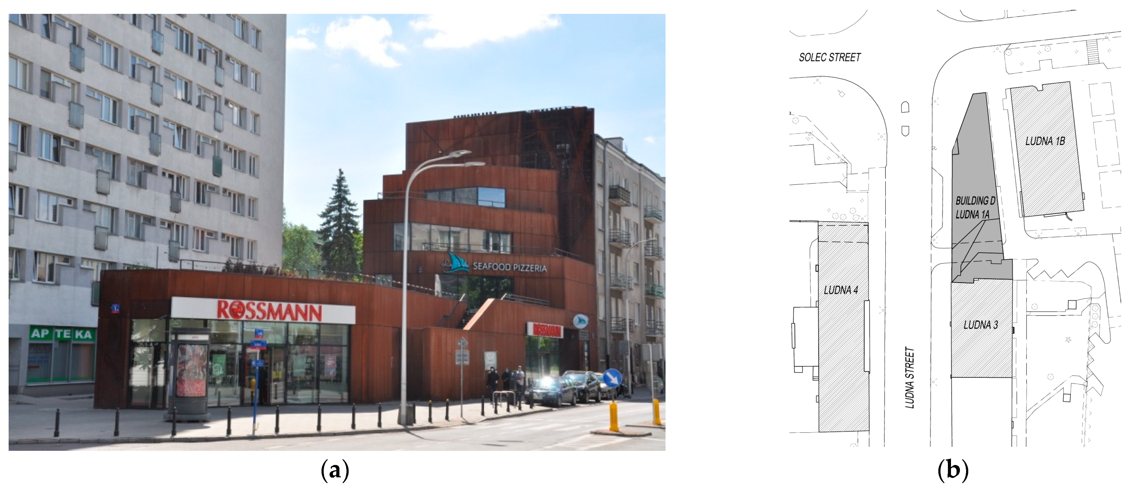
The subject of our research is the commercial, service, and office building D located at 1A Ludna Street in Warsaw (Figure 1) [50].
In the vicinity of this building, there is (Figure 1b):
- a historic, modernist tenement house with 5 overground floors dating from 1935 at 3 Ludna Street;
- a multi-family residential building with 17 aboveground floors at 1B Ludna Street;
- a residential and service building with 4 overground floors at 4 Ludna Street.
2.1.1. Building D
The aboveground structure is made of reinforced concrete with a monolithic, column-wall-slab skeleton. The building has four overground floors and one underground floor which is below the part of the building intended for technical and storage rooms [Domurad, J., Kościuch, P., Domurad, J., Karwan, R. Structural design of diaphragm walls, temporary strutting, and Solec/Ludna/Wilanowska piles. Warszawa 2016].
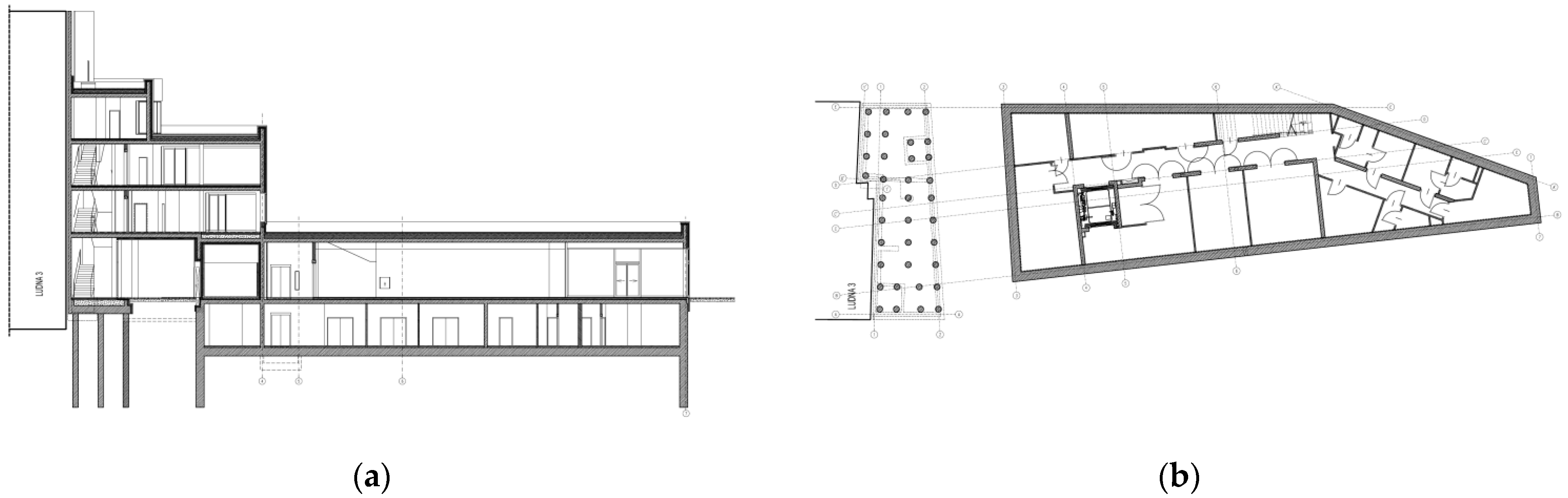
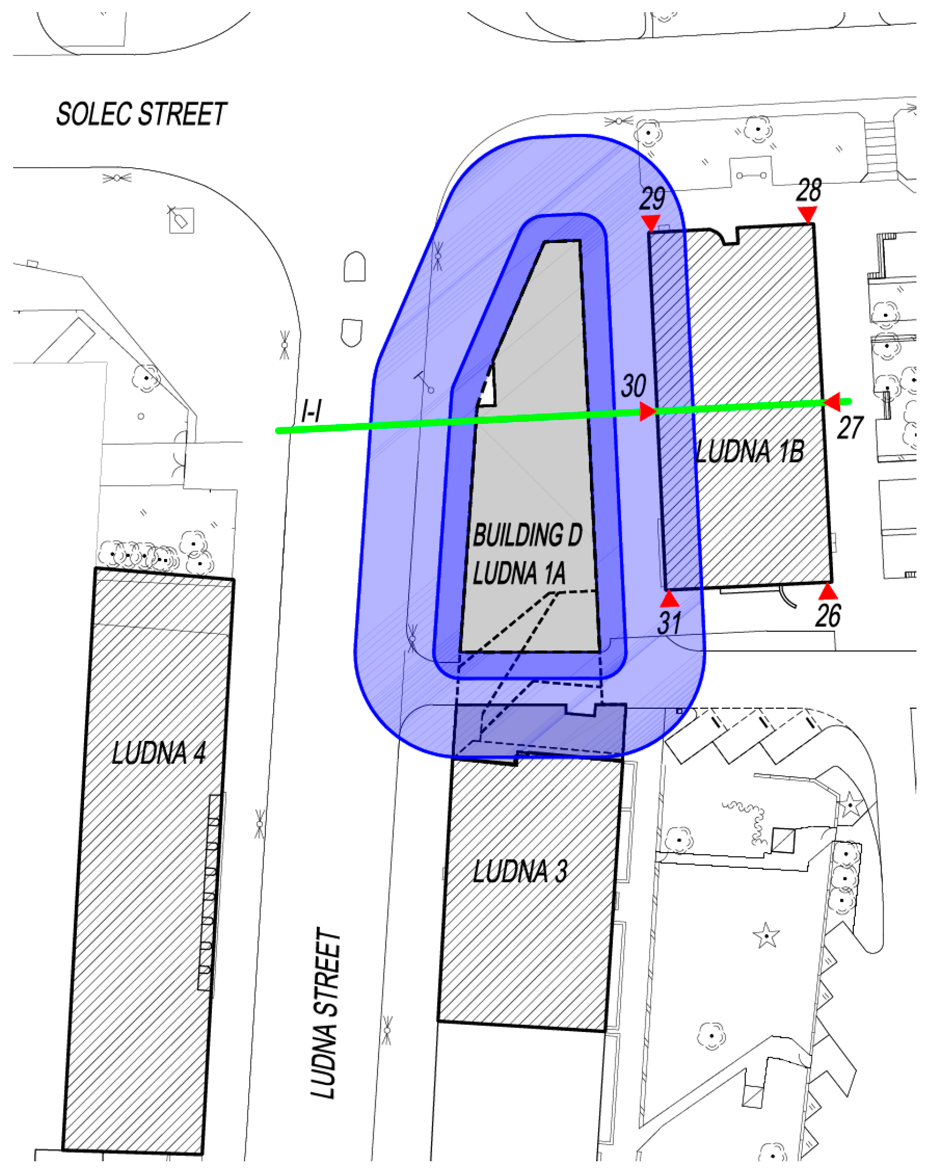
The overground part of the building is directly adjacent to the one at 3 Ludna Street, while the underground part is separated from the outer walls of the basement in the building at 3 Ludna Street by a distance of around 9.3 m (Figure 2).
The foundation slab with slopes towards the channel drainage was designed and made from waterproof concrete.
2.1.2. Adjacent Development
The investment preparation phase involved an assessment of the technical condition of the buildings situated in the vicinity of the target building. Below are listed some relevant design factors (Szulborski, K., Majewska, A., Michalak, H., Paziewski, T., Pęski, S., Przybysz, P., Pyrak, S.). Technical expertise of the adjacent development and assessment of the impact of the SBM TORWAR residential complex at Solec/Ludna/Wilanowska Streets in Warsaw, Warsaw 2010.
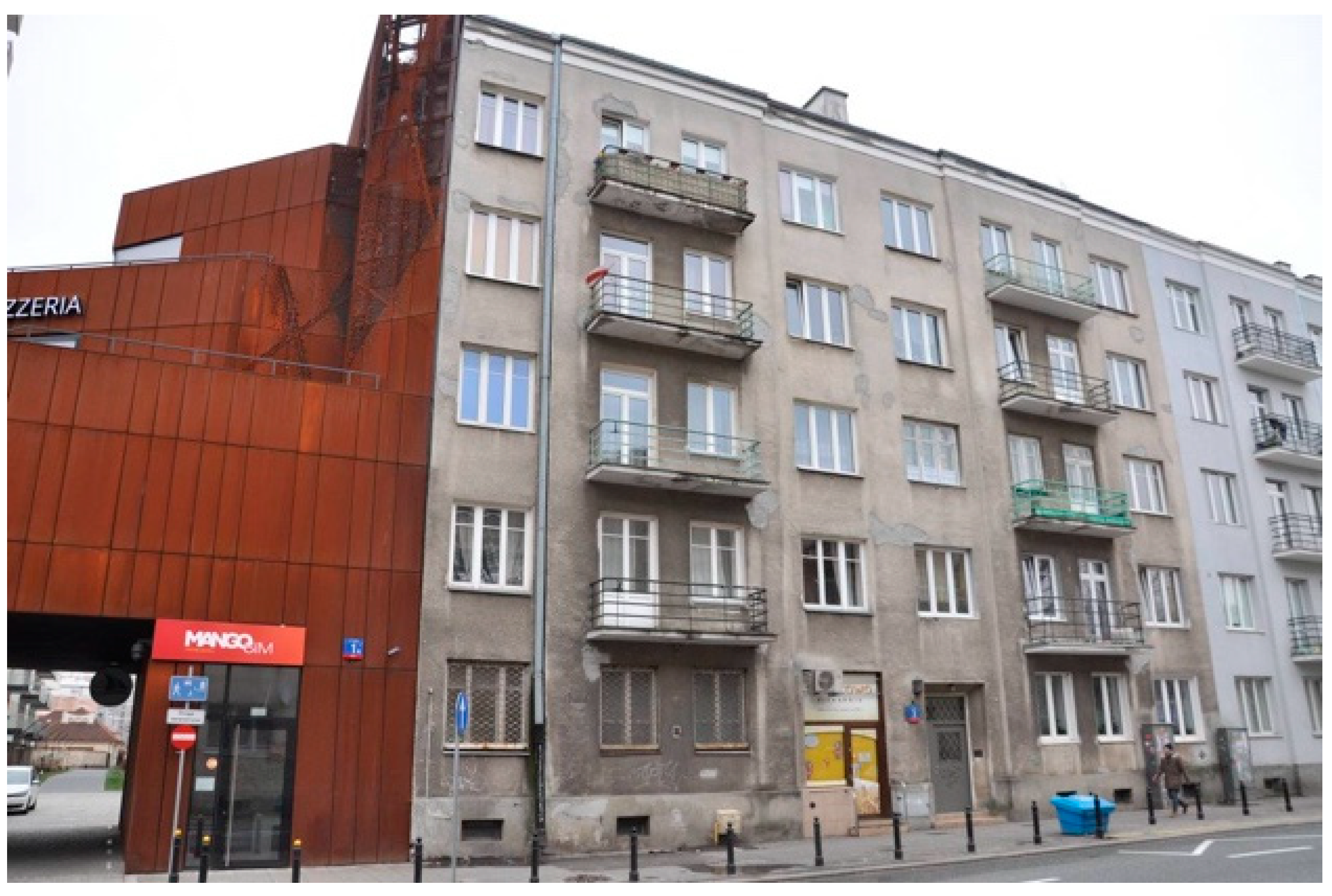
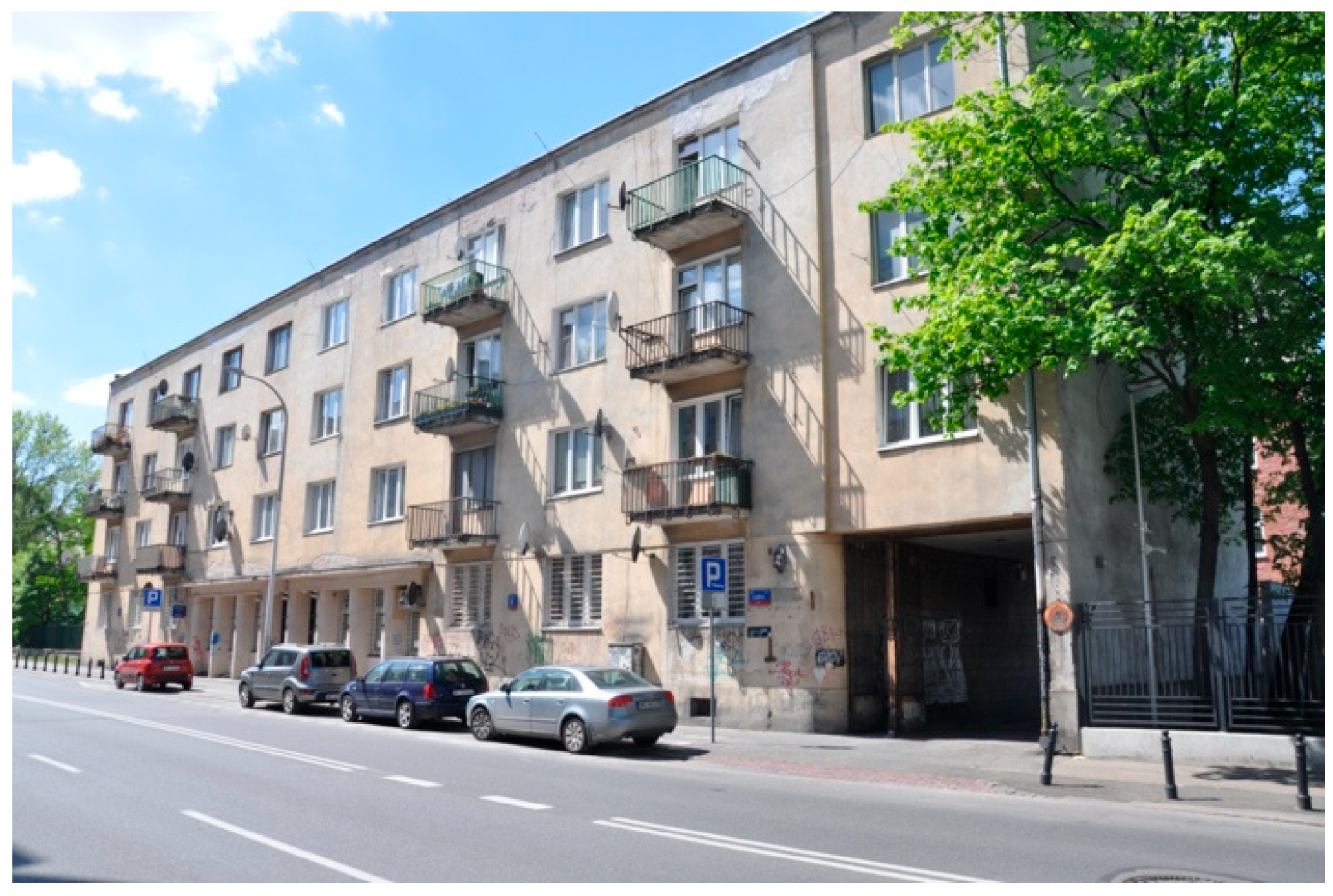
Tenement house, 3 Ludna Street: The modernist tenement house dating from 1935 at 3 Ludna Street (Figure 3) is listed in the municipal monuments’ register. The tenement house has a basement and five overground floors. It has a structure made from solid ceramic bricks, a longitudinal load-bearing wall system, Klein ceilings supported by steel beams (above the basement and attic), and “Polonia” monolithic closely ribbed ceilings. The ceilings are filled with hollow brick.
The shape of the building resembles a rectangle with the following dimensions: length—25.80 m (dimension parallel to the axis of Ludna Street, see Figure 1); width—14.32 m. The height of the building, measured from the ground level to the ridgepole, is 19 m. The external structural walls are made of ceramic brick, full thickness, with 2 bricks used on the basement and ground floor levels and 1 brick used on the fourth floor and attic levels.
The building is set directly on the foundation footings, which are probably made from brick. The foundation level has been estimated to be 3.7 m below the level of the surrounding area at the entrance.
The building has one circulation path located in the middle and a refractory structure. There is a gable roof and a wooden rafter-purlin framework.
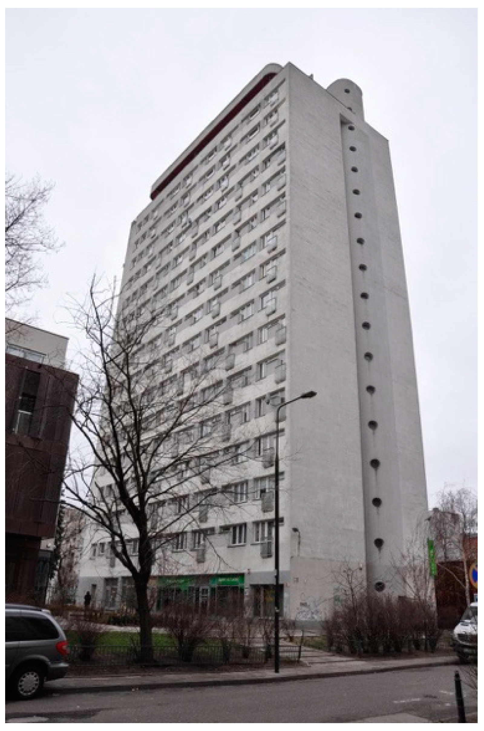
Residential building at 1B Ludna Street: The building is over 50 m high, as measured from the ground surface, and is one of the highest in this part of Śródmieście (city center) (Figure 4). The structure is made of reinforced monolithic concrete, wall-type, with a transverse arrangement of load-bearing walls and inter-story multi-rib ceilings. It is stiffened with rims situated at the ceiling level, lintels, downstand beams, and wind walls.
The foundation level is 3.91 m below the level of the surrounding area. It is made of 30 cm-thick reinforced concrete slabs with ribs with a section height of 140 cm.
The load-bearing walls are made from reinforced concrete monolithic structures with a thickness of 35 cm that are spaced transversely every 3.60 m and at the staircase every 5.40 m. The load-bearing walls in the basement and ground floor are 35 cm thick, the outer walls of the underground floor are 30 cm-thick reinforced concrete monolithic structures, and the load-bearing walls on other floors and in the lift shafts are 20 cm thick.
The basement, ground floor, and 16th floor are covered with DZ-3 ceilings, while the remaining parts are covered with 18 + 3 cm-thick Ackerman ceilings. The structure of the flat roof consists of prefabricated hollow core-reinforced concrete plates.
Residential building at 4 Ludna Street: This building was erected after 1935 as a residential building for employees of the Ministry of Post and Telegraphs. A post office is situated on the ground floor. It has 4 overground floors and a basement. The building is made of traditional brick (Figure 5).
2.1.3. Ground
The Solec/Ludna/Wilanowska building complex is located approximately 150 m from the Vistula riverbed. Geotechnical studies have revealed that the first level of groundwater occurs at a depth of 3.5 to 5.5 m below sea level.
The ground in the area of this development is composed of the following geotechnical layers (from the top):
- rubble stone embankments with an admixture of sand and clays with a thickness of 1.0 to 3.8 m;
- a discontinuous layer of clay and sandy loam with an admixture of organic parts in both hard and plastic states (IL = 0.1 ÷ 0.2; angle of internal friction φ = 15°; volume density γ = 21.5 kN/m3; Poisson’s constant ν = 0.32; cohesion cu = 17 kPa, primary deformation modulus E = 10,500 kPa) and locally in a plastic state (IL = 0.3), with a thickness of up to 2.0 m;
- medium and coarse sands in a medium compacted state, with a thickness of 2.5 to 5.5 m; locally, there are fine sands and medium-compacted dusty sands as well as semi-compact dusty formations (ID = 0.4 ÷ 0.6; φ = 34°; γ = 19.0 kN/m3; ν = 0.25; E = 91 700 kPa);
- Pliocene clays in both hard-plastic and semi-compact states, occurring from a depth of 5.0 to 8.0 m below sea level (φ = 13°; γ = 21.0 kN/m3; ν = 0.37; cohesion cu = 60 kPa, primary deformation modulus E = 17,000 kPa).
Building D is situated in a layer of medium-compacted sands, about 2.0 m below the maximum level of the groundwater table.
2.1.4. General Characteristics of the Design Concept of the Underground Part of Building D at 1A Ludna Street
The development of this building was preceded by the gathering of expertise regarding the technical condition of the neighboring buildings. The above, paired with the results of geotechnical research, was used to gain technical insight regarding the potential impacts of the construction of the underground part of a new building on the adjacent developments (Szulborski, K., Majewska, A., Michalak, H., Paziewski, T., Pęski, S., Przybysz, P., Pyrak, S. Technical expertise of the adjacent development and assessment of the impact of the SBM TORWAR residential complex at Solec/Ludna/Wilanowska Streets in Warsaw, Warsaw 2010). The soil-water conditions, the excavation of the diaphragm walls, and the depth of excavation for the underground part of building D (amounting to about 4.15 m below ground level) were considered to determine the ranges of the excavation’s possible zones of impact [4,10,15]. In the case of zone I, i.e., the direct impact of the excavation, this range was determined to be 2.30 m from the face of the diaphragm wall, while in the case of zone II, i.e., the indirect impact, this range was determined to be 9.20 m (Figure 6).
The building at 1B Ludna Street is situated in zone II. The maximum vertical displacements of subsoil which would not require the structures of the existing buildings to be reinforced were determined to be 12 mm in zone I and 8 mm in zone II.
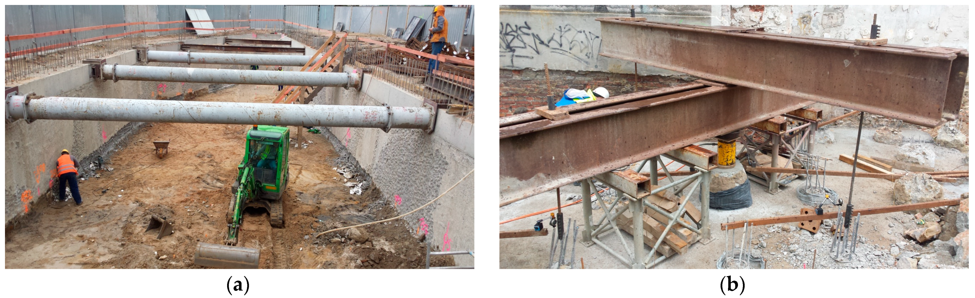
With respect to the construction of the discussed complex in a dense downtown development, the historic character of a major part of this development, and the soil-water conditions in the area, 60 cm-thick diaphragm walls were used for excavation support as well as for the external walls of the underground section (Figure 7). The depth of the diaphragm walls of building D varied from 8.0 to 9.5 m below the ground; the walls were adapted to the ground conditions, loads, and the geometry of the foundation slab. The diaphragm walls were sunk into cohesive soil in order to prevent the inflow of groundwater to the interior of the excavation. In order to ensure the safety of the buildings closest to the excavation, the diaphragm wall was constructed in 2.8 m-long sections.
No underground part was built on the side facing the tenement house at 3 Ludna Street (see Figure 2); instead, this part of the building without a cellar was placed on CFA piles with a diameter of 40 cm (see Figure 7b) and length of 8.0 to 9.0 m.
The stability of the diaphragm wall during the sinking of the excavation to the bottom of the foundation slab was ensured by using support struts made of 502/12.5 mm steel pipes and HEB 300 I-sections. After the foundation slab was constructed and the concrete had achieved the designed strength, the struts were dismantled, and the diaphragm walls were used as cantilevers until the ceiling was constructed above the level of −1.
2.1.5. Geodetic Monitoring
During the construction works, we carried out geodetic and visual observations of the neighboring buildings located in the 2nd zone of impact, as well as observations of the diaphragm walls. The vertical displacements of benchmarks located on adjacent buildings, the horizontal displacements of stabilized benchmarks on selected buildings, and the horizontal displacements of diaphragm walls and scratches with respect to the buildings were measured. The frequency of measurements depended on the stage the construction work was in.
2.2. Methods—3D Numerical Model of the System “Subsoil—New Building—Adjacent Development”
2.2.1. Basic Assumptions
For the numerical modeling of the “subsoil—new building D—adjacent development” system, we structured the phases of work according to the actual stage the building construction was in. The values of the loads of the buildings and the method and placement of their application were determined on the basis of the analysis of the design documentation and our own experience.
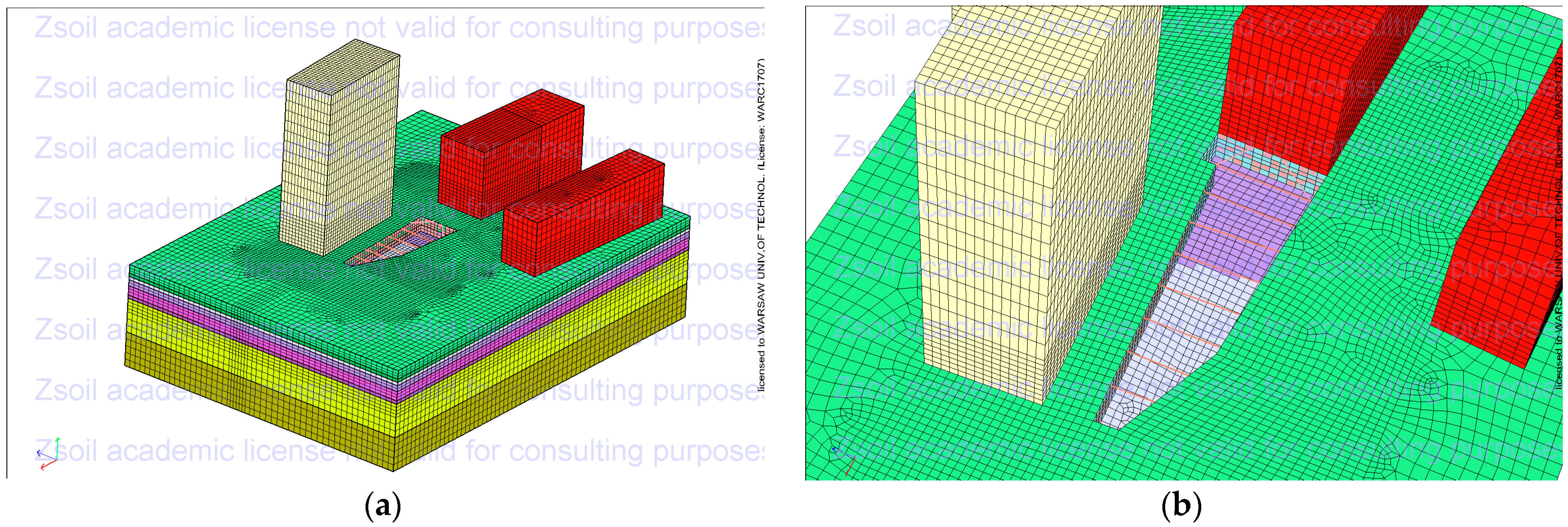
The spatial numerical models of the “subsoil—new building D—adjacent development” system, including building D and the adjacent development, were built in the ZSoil 2016 program by ZACE Services Ltd. [51,52,53].
The numerical model mapped a total area of 120 × 90 m, including the new building D and the adjacent developments—tenement houses at 3 Ludna Street (see Figure 3) and 4 Ludna Street (see Figure 5) and the building at 1B Ludna Street (cf. Figure 4). The subsoil was modeled to a depth of 30 m.
One calculation file contains a model of all the construction phases of building D. This model was created using two-dimensional surface and bar finite elements, which were used to recreate the diaphragm walls, diaphragm wall strutting, internal walls, foundation slab, and ceiling above level −1. The elements were given thicknesses and material characteristics consistent with the design assumptions.
The aboveground part was mapped as three-dimensional finite elements [32,33,34], which were given the value of the reduced modulus of elasticity, taking into account the stiffness of the buildings’ aboveground parts resulting from the construction materials and material data used, including the Poisson’s ratio. The method used for modeling the aboveground parts of the buildings resulted in a simplification of the model and a reduction in the number of finite elements involved, calculating this model producible for the computational capabilities of the equipment used.
The dimensions used for the finite elements of the underground part of this building were 1.0 × 1.0 × 1.0 and 2.0 × 2.0 × 1.0 m, while the dimensions of the finite elements of the aboveground part were 1.0 × 1.0 × 1.0 m.
The building load was calculated taking into account the actual dead loads of the structures and the finishing elements, as well as useful loads.
This load, relating to the individual phases of works, was modeled as a variable in time and included in the calculations according to their actual application based on the building’s construction schedule. These loads in the model were applied on the level of the “roof” surfaces.
The neighboring buildings were fully modeled (together with the underground parts) using three-dimensional finite elements. As in the case of the aboveground part of the building in question, these elements were given the value of the reduced modulus of elasticity, taking into account the stiffness of the buildings. The adopted dimensions of the finite elements were up to 1.0 × 1.0 × 3.0 m.
The spaces between the individual buildings of the modeled area were filled with dilatation elements according to the location of their actual occurrence, enabling the independent deformation of these buildings in this respect [32].
The subsoil under the buildings was modeled to a depth of 30 m below ground level. For the analysis, we used the Mohr–Coulomb substrate nonlinear model. The spatial arrangement of the soil layers was modeled on the basis of the results of soil tests from exploratory wells. The strength parameters of the soil layers below the exploration level were extrapolated. The numerical model of the subsoil was calibrated on the basis of the results of geodetic measurements [4,32,33,34].
2.2.2. Shape Variants of the Underground Part of Building D at 1A Ludna Street
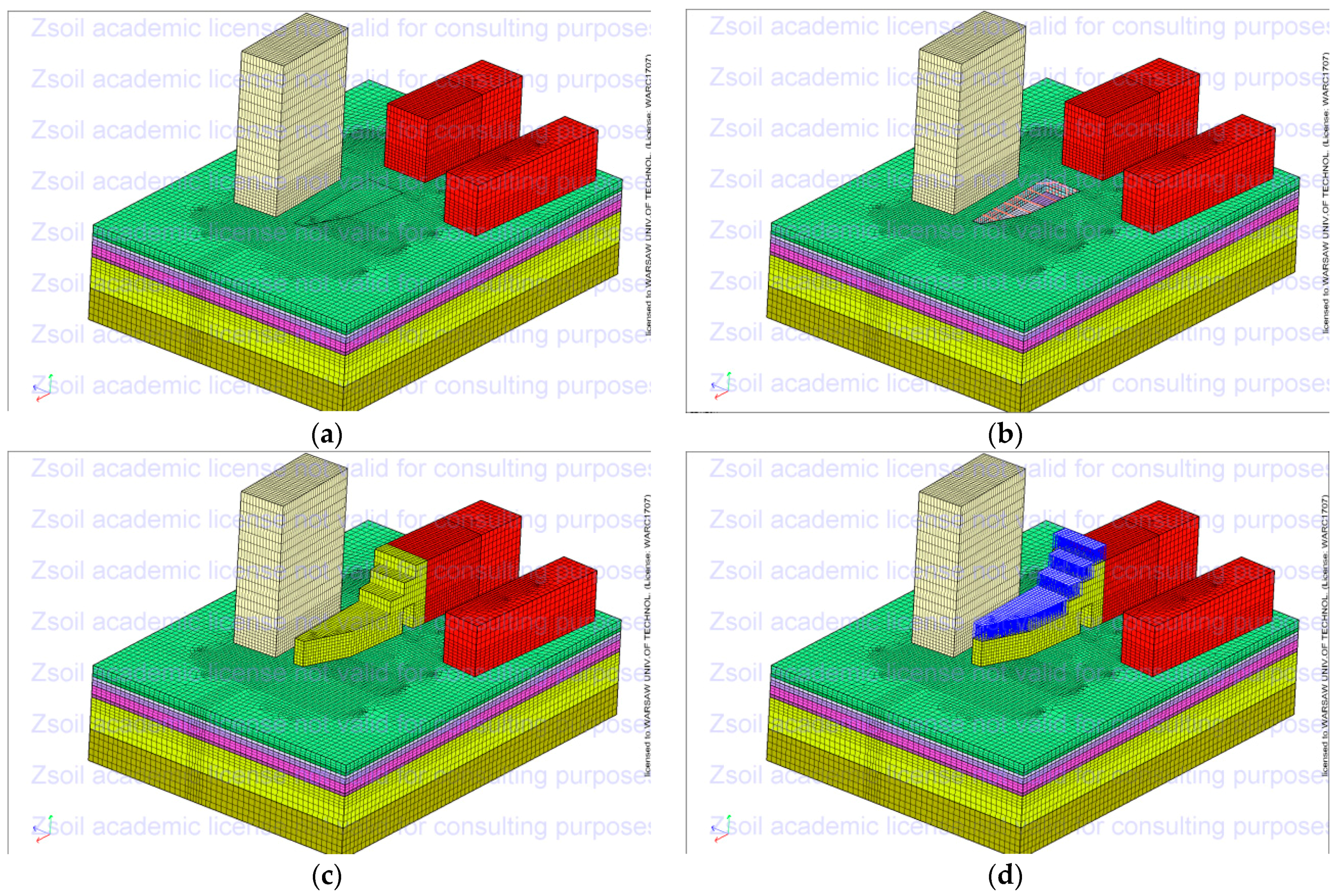
Modeling was carried out in 4 shape variants of the underground part of building D (Figure 8).
- Variant A
The first variant A (see Figure 8a) reflects the completed investment. It was assumed that one underground floor was built under part of the building at a distance of about 9.3 m from the outer underground walls of the tenement house at 3 Ludna Street (cf. Figure 3). The underground part of the building would have a 60 cm-thick diaphragm wall based on a 60 cm-thick reinforced concrete slab. During excavation, the stability of the diaphragm walls would be ensured by the use of steel struts. In the part constructed without a cellar, we assumed that the foundation of the new building would be based on drilled CFA piles with a diameter of 40 cm.
- Variant B
This theoretical variant assumed that one underground floor would be built underneath the entire building (cf. Figure 8b). It was presumed that the underground part would be constructed with the support of diaphragm walls with a thickness of 60 cm and that the foundation would rest on a reinforced concrete foundation slab with a thickness of 60 cm. During excavation, the stability of the diaphragm walls would be provided by steel struts.
- Variant C
This theoretical variant assumes the construction of two underground floors under the main part of the building and no underground section on the side facing the tenement house at 3 Ludna Street (cf. Figure 8c). The underground part would be designed with a 60 cm-thick diaphragm wall and set on a 60 cm-thick reinforced concrete slab. Due to the foundation being below the groundwater level, drainage was assumed to occur from the area surrounded by diaphragm walls anchored in the layer of impermeable clay. During excavation, the stability of the diaphragm walls would be ensured by the use of steel struts at level 0 and above the ceiling of level −2. In the part without cellars, the foundation of the new building was assumed to be based on drilled CFA piles with a diameter of 40 cm.
- Variant D
This theoretical variant assumes that two underground floors would be built underneath the entire building (see Figure 8d). The underground part of the building would be designed with a 60 cm-thick diaphragm wall and set on a 60 cm-thick reinforced concrete slab. As it has a foundation below the groundwater level, it was assumed that water would be pumped from the area enclosed by diaphragm walls anchored in the layer of impermeable clay. During excavation, the stability of the diaphragm walls would be ensured by the use of steel struts at level 0 and above the ceiling of level −2.
3. Results
3.1. Results of Numerical Analyses of Four Shape Variants of the Underground Part
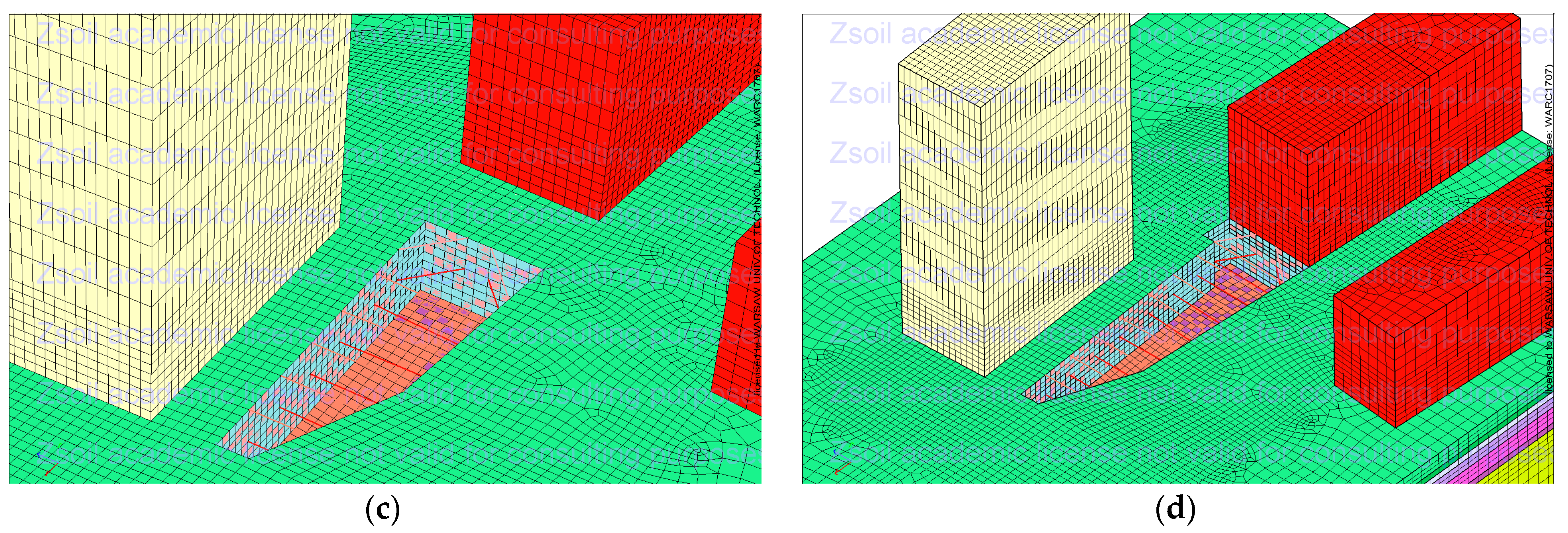
Three-dimensional numerical analyses of the model reproducing the actual phases of the work implementation were carried out (Figure 9). Variant A and the values of vertical displacements obtained from the geodetic measurement of benchmarks on neighboring buildings were compared. Due to the accuracy of the measurements of vertical displacements being ±0.3 mm, the results of the measured values of vertical displacements and the displacements calculated in the numerical analyses, which differed by no more than 0.6 mm, were considered convergent [4].
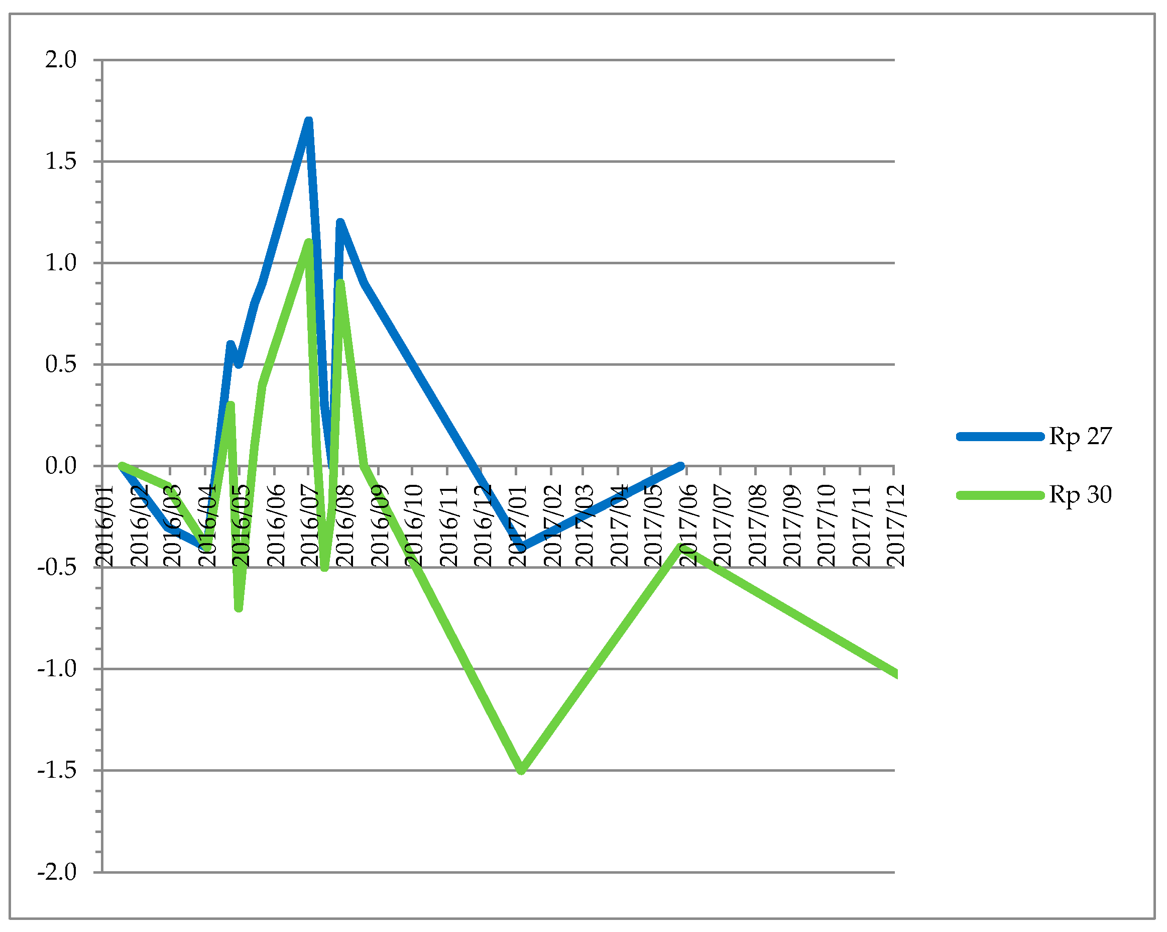
Detailed comparative analyses were carried out for the part with an underground floor made with one technology (i.e., in an excavation pit protected by diaphragm walls stretched at a certain height) in the vicinity of a high-rise building at 1B Ludna Street. Comparative analyses of the measured vertical displacements (Figure 10) and those obtained from numerical analyses in variant A (Table 1 and Table 2) revealed the conformity of the results.
The measurement results for the implementation of the aboveground part and the application of the full payload are characterized by a greater difference in value than the assumed value of −0.6 mm. There is a direct link with the lack of a geodetic measurement corresponding to the stabilization of vertical displacements applied to the inhomogeneous subsoil, which occurs in the period 1–3 years from the application of the full load [4]. The geodetic measurement was performed immediately after the application of this load (see Figure 10).
It follows from the comparative analysis of the geodetic results for the measurements of vertical displacements of the Rp30 benchmark located 6.1 m from the edge of the excavation with the values of these displacements obtained from the actual implementation of the numerical model in variant A that (cf. Table 1) the noticeable subsidence (measured value −0.4 mm) occurred in the phase related to the construction of the diaphragm walls. Then, during the phases related to the execution of the excavation 4.15 m below the ground level, there were vertical displacements in the opposite direction upwards—i.e., uplift (measured value 0.4 mm). The subsequent phases of works related to the construction of the underground and aboveground parts and the application of the operational load resulted in the subsidence of the subsoil (measured value: −1.1 mm).
In a comparative analysis of the results of geodetic measurements of vertical displacements of the Rp27 benchmark situated at a distance 20.6 m from the edge of the excavation with the values of these displacements obtained from the actual implementation of the numerical model in variant A, it follows (cf. Table 2) that noticeable subsidence (measured value −0.4 mm) occurred in the phase related to the execution of the diaphragm walls. Then, the phases related to the execution of the excavation at a depth of 4.15 m below ground level were followed by vertical displacements in the opposite direction (upwards)—i.e., uplift (measured value 0.9 mm). The subsequent phases of works related to the construction of the underground and aboveground parts and after the application of operational load resulted in the slight subsidence of the soil subbase and, consequently, the balancing of the previously existing upheavals. It is recalled that the eastern part of the building (benchmark Rp27)—classified as situated outside zone II—showed slight displacements in the phase of the greatest impacts related to the deepening of the excavation. In the remaining phases, these displacements did not exceed the twofold error of geodetic measurements.
Taking into account the reservations and remarks presented above regarding the scope of compliance of the results obtained from the numerical model in variant A and geodetic measurements during the investment implementation, it was found that this may constitute the basis for the further analysis of various suggestions for shaping the underground part of the new building, including the diversification of the number of underground floors.
3.2. Variants of the Aboveground Part of Building D at 1A Ludna Street
We carried out 3D numerical analyses of the shape of the aboveground part of the analyzed building D, which presented an increase in the number of aboveground floors by one, two, three, and four floors in relation to the implemented case (Figure 11). These analyses were carried out in all shape variants of the underground part—i.e., variants A, B, C, and D. The essential purpose of these theoretical analyses was to determine (in the case of the legal conditions of the investment area in question, the construction of a building with a greater height that is more favorable in terms of the usable area will also be achieved) the impact of the investment on the existing development and the possibility of implementation without the need to strengthen its structure.
3.3. Variants Results of Numerical Analyses of Four Shape Variants of the Aboveground Part
A tabular listing of the vertical displacements of the new building D on Ludna Street can be seen in Table 1. From the results obtained from the numerical model, it can be concluded that the vertical displacements at this point in each of the analyzed shape variants of the underground and aboveground parts of the building D have a subsidence character.
These subsidence values obtained from numerical models in the case of the actual variant of the underground part—i.e., variant A—are −3.0 mm; in theoretical cases of increasing the number of aboveground floors, they are from −3.8 mm (one additional aboveground floor) to −5.9 mm (four additional overground floors).
In the subsequent analyzed theoretical cases of the shape of the underground part (variants B, C, and D) and the aboveground part of new building D, the building subsidence in the analyzed point of the nearest wall of the adjacent high building at 1B Ludna Street for the aboveground part is, respectively (Table 3):
- Realized with the actual height from −3.1 (variant B) to −5.3 mm (variant D);
- With an additional floor from −3.8 (variant B) to −5.9 mm (variant D);
- With two additional floors from −4.5 (variant B) to −6.4 mm (variant D);
- With three additional floors from −5.3 (variant B) to −7.0 mm (variant D);
- With additional four floors from −6.0 (variant B) to −7.4 mm (variant D).
The vertical displacements of the building at 1B Ludna Street at the site of benchmark 27 (see Figure 6) located 20.6 m from new building D have small values ranging from +0.8 to −0.5 mm and have the nature of uplifts in variants A and B as well as subsidence in the case of variants C and D.
These vertical displacements in the variant have values of:
- A: +0.4 mm (actual height of the new building D); +0.4 mm (additional 1 floor) to +0.8 mm (additional 4 aboveground floors);
- B: +0.2 mm (actual height of the new building D); +0.4 mm (additional 1 floor) to +0.8 mm (additional 4 aboveground floors);
- C: −0.3 mm (actual height of the new building D); −0.2 mm (additional 1 floor) to 0.0 mm (additional 4 aboveground floors);
- D: −0.5 mm (actual height of the new building D); −0.4 mm (additional 1 floor) to −0.1 mm (additional 4 aboveground floors).
4. Discussion
Comparing variants A and B of the investment, taking into account the differentiation of the outline of the underground part, it can be concluded that the construction of the underground floor beneath the entire site of the building using one technology (in the vicinity of the high-rise building at 1B Ludna Street) causes no noticeable changes in the values of the vertical displacements of the subsoil, which do not exceed the value of twofold error of geodetic measurement. It can therefore be concluded that it is possible to build the underground part beneath the entire plan of the building and, Consequently, increase the cubature of its underground part in variant B in relation to the realized (actual) variant A.
A comparative analysis of the results obtained from the numerical models for variants A and C—i.e., increasing the number of underground floors in the same part of the building from 1, in the case of implemented variant A, to 2 floors (as in variant C)—revealed, among other things:
- An increase in the depth of the excavation from 4.15 to 8.0 m and, consequently, an increase in the range of the impact of zone I of the excavation to about 4.4 m on the face of the diaphragm wall and of zone II to about 17.7 m;
- An increase in the height of diaphragm walls from 8.0–9.5 m (variant A) to 14 m (variant C);
- In the case of the western wall of the building, there was a significant increase in the vertical displacements in the phases (cf. Table 1): the execution of the diaphragm walls—from −0.9 mm (variant A) to −1.8 mm (variant C); the execution of the excavation to the designed depth from 0.2 mm (variant A, one underground floor) to −2.4 mm (variant C, two underground floors); the erection of the aboveground part of the new building from −2.5 mm (variant A) to −3.9 mm (variant C); the application of the payload from −3.0 mm (variant A) to −4.3 mm (variant C);
- In the case of the eastern wall of the building, there were slight increases/changes in vertical displacements in the phases (cf. Table 2): the execution of the excavation to the designed depth from −0.4 mm (variant A, one underground floor) to −1.1 mm (variant C, two underground levels); the erection of the aboveground part of the new building from 0.3 mm (variant A) to −0.4 mm (variant C); the application of the live load from 0.4 mm (variant A) to −0.3 mm (variant C).
Comparing variants A and D of the investment, taking into account the differentiation of the outline of the plan of the underground part and the depth of the foundation, it can be concluded that:
- The increase in the depth of the excavation and the zone of impact of the new implementation (within the part of the analyzed investment with the underground part implemented using one technology—diaphragm walls) is identical in variants D and C (as presented above);
- In the case of the western wall of the building, there was a significant increase in vertical displacements in the phases (cf. Table 1): the execution of the diaphragm walls from −0.9 mm (variant A) to −1.5 mm (variant D); the execution of the excavation to the designed depth from 0.2 mm (variant A, one underground floor) to the value of −3.6 mm (variant D, two underground levels); the erection of the aboveground part of the new building from −2.5 mm (variant A) to −4.8 mm (variant D); the application of a live load from −3.0 mm (variant A) to −5.3 mm (variant D);
- In the case of the eastern wall of the building, there were slight increases/changes in vertical displacements in the phases (cf. Table 2): the execution of the excavation to the designed depth from −0.4 mm (variant A, one underground floor) to −1.4 mm (variant D, two underground floors); the erection of the aboveground part of the new building from 0.3 mm (variant A) to −0.5 mm (variant D); the application of the payload from 0.4 mm (variant A) to −0.5 mm (variant D).
By conducting a comparative analysis of the variability range of vertical displacements concerning the western wall of the building (located 6.1 m from the new building at 1A Ludna Street), it can be concluded that the results were:
- Actual geodetic measurements (benchmark Rp30)—from 0.4 to −1.1 mm;
- Numerical model variant A—from 0.2 to −3.0 mm;
- Numerical model variant B—from 0.1 to −3.1 mm;
- Numerical model variant C—from 0.0 to −4.3 mm;
- Numerical model variant D—from 0.0 to −5.3 mm.
The investment preparation phase involved the performance of diagnostics of buildings situated within the range of impact (in zones I and II). The result enabled us to establish the permissible vertical displacements of these buildings—i.e., when located in zone I (building at 3 Ludna Street), 12 mm, and when located in zone II (building at 1B Ludna Street), 8 mm. During the design and static calculation of the excavation support for the underground part of the new building, the horizontal displacements of the lining were determined and the possible vertical displacement of the subsoil in the immediate vicinity was estimated. The basis for this was the results of the research and observations included in [4,10,18]. The values of the predicted displacements did not exceed the permissible values of vertical displacements specified for the building in question (Szulborski, K., Majewska, A., Michalak, H., Paziewski, T., Pęski, S., Przybysz, P., Pyrak S.). Technical expertise of the neighboring buildings and assessment of the impact of the complex SBM TORWAR housing at Solec/Ludna/Wilanowska Streets in Warsaw. Warsaw 2010. For these reasons, during the implementation of the investment it was only recommended that we conduct geodetic and visual monitoring to control the displacement of the excavation support as well as for the buildings located within the zones of impact.
The vertical displacements of the subsoil and the neighboring buildings determined in all analyzed variants A–D of the 3D numerical models showed values lower than those considered acceptable due for the safety of use of this building. For these reasons, the analyses could form the basis for the selection of the best solution, taking into account the criterion adopted by the investor.
Based on the obtained results for the vertical displacements of the existing building at 1B Ludna Street, it can be concluded that, in the case of all shape variants of the underground part and the body of the aboveground part of the new building, The displacements obtained were within the permissible range (up to 8 mm) specified in the technical requirements of the existing buildings.
Due to the aforementioned factors and in the absence of legal conditions, including legal restrictions on the possible expansion of the body of the new building in the design concept phase, the presented variants could constitute the basis for selecting the most favorable development—e.g., due to the criterion of obtaining the largest usable area for the underground and aboveground parts of the new building.
5. Conclusions
In this paper, the authors presented the results of their research concerning the use of 3D numerical models and verified them taking into account the actual results of geodetic measurements for shaping the underground parts of the designed buildings in a dense urban development.
Appropriately designed 3D numerical models make it possible to forecast the impacts within the newly designed buildings and adjacent development, and, after their appropriate calibration, reflect the displacements of the subsoil in the area of the planned investment. Knowledge of the anticipated displacements of the subsoil related to the new development is necessary in the investment design and implementation phases due to the need to ensure the safety of erection and use of a new building, as well as the use of facilities located in the zones of impact.
Three-dimensional numerical models enriched with a number of variants for shaping the underground and aboveground parts of the new building in a compact urban allow for a more complete reflection of the impact of a new development and help to determine the technical conditions required for its implementation.
For these reasons, after analyzing the existing technical conditions the basis for choosing the most advantageous solution may be criteria important for the investor—e.g., the biggest usable area of the underground and aboveground parts of the new building.
The proposed topic is based on the need to outline the necessity and appropriateness of the extension of studies and analyses relating to construction projects involving the development of a new building in a compact urban area.
This type of study allows the developer and designer to make the most favorable decisions concerning the proper design of the underground part of the building. At the same time, it helps to point out the consequences of such a development, including the risks involved, the limitations, and the possible claims of the owners of existing buildings in the neighborhood resulting from damage caused by the new structure. It identifies the factors that are necessary to consider when preparing the construction of a structure with a deep foundation in a compact urban area, helping ensure that the implementation of the project can be appropriately completed.
The authors consider it advisable to continue and extend this research to include analyses—within the scope presented in the article—of new cases of constructions carried out in dense urban developments with different foundation depths corresponding to 1 to 5 underground stories.
Author Contributions
Conceptualization, methodology, formal analysis, investigation, writing—original draft preparation, writing—review and editing, H.M. and P.P.; supervision, H.M. All authors have read and agreed to the published version of the manuscript.
Funding
The work was carried out as part of the authors’ employment and statutory activity at the Faculty of Architecture of the Warsaw University of Technology. Statutory work no. 504/04190/1010.
Institutional Review Board Statement
Not applicable.
Informed Consent Statement
Not applicable.
Data Availability Statement
Not applicable.
Acknowledgments
The authors would like to thank the Torwar Construction and Housing Cooperative (Spółdzielnia Budowlano-Mieszkaniowa Torwar) in Warsaw for providing the starting and reference materials for this research.
Conflicts of Interest
The authors declare no conflict of interest. The funders had no role in the design of the study; in the collection, analysis, or interpretation of data; in the writing of the manuscript; or in the decision to publish the results.
References
- Michalak, H. Selected problems of designing and constructing underground garages in intensively urbanized areas. In Underground Infrastructure of Urban Areas; Madryas, C., Przybyła, B., Szot, A., Eds.; CRC Press/Balkema Taylor & Francis Group A Balkema Book: London, UK, 2009; pp. 193–201. [Google Scholar]
- Xie, H.; Zhang, Y.; Chen, Y.; Peng, Q.; Liao, Z.; Zhu, J. A case study of development and utilization of urban underground space in Shenzhen and the Guangdong-Hong Kong-Macao Greater Bay Area. Tunn. Undergr. Space Technol. 2021, 107, 103651. [Google Scholar] [CrossRef]
- Bobylev, N. Underground space as an urban indicator: Measuring use of subsurface. Tunn. Undergr. Space Technol. 2016, 55, 40–51. [Google Scholar] [CrossRef] [Green Version]
- Michalak, H. Spatial and Structural Planning of Underground Garages on Highly Urbanized Areas, 1st ed.; Architecture Series; Publishing House of Warsaw University of Technology: Warsaw, Poland, 2006; pp. 25–51. (In Polish) [Google Scholar]
- Jiang, S.; Wang, Y. Long-Term Ground Settlements over Mined-Out Region Induced by Railway Construction and Operation. Sustainability 2019, 11, 875. [Google Scholar] [CrossRef] [Green Version]
- Agnella, D.; Giannotti, W.J.; Rosatti Filho, M.A.; Oliveira Pires, T. PAT TBM improving—A case study to Metro Sao Paulo. In Geotechnical Aspects of Underground Construction in Soft Ground, Proceedings of the 9th International Symposium on Geotechnical Aspects of Underground Construction in Soft Ground, Sao Paulo, Brazil, 4–6 April 2017; Negro, A., Cecílio, M.O., Jr., Eds.; Taylor & Francis Group: London, UK, 2018. [Google Scholar]
- Ramadan, E.H.; Ramadan, M.; Khashila, M.M.; Kenawi, M.A. Analysis of Piles Supporting Excavation Adjacent to Existing Buildings. In Proceedings of the 18th International Conference on Soil Mechanics and Geotechnical Engineering, Paris, France, 2–6 September 2013; pp. 2835–2838. Available online: https://www.researchgate.net/publication/272507779 (accessed on 2 December 2020).
- Liu, H. Effect on Existing Building by Foundation Pit Excavation. EJGE 2014, 19, 6735–6746. Available online: http://www.ejge.com/2014/Ppr2014.610ma.pdf (accessed on 2 December 2020).
- Liu, H. Existing Building Stability Evaluation by Deep Foundation Pit Construction of Subway Station. EJGE 2015, 20, 1857–1868. Available online: http://www.ejge.com/2015/Ppr2015.0256xg.pdf (accessed on 2 December 2020).
- Breymann, H.; Freiseder, M.; Schweiger, H.F. Deep excavations in soft ground in-situ measurements and numerical predictions. In Proceedings of the XIV International Conference on Soil Mechanics and Foundation Engineering, Hamburg, Germany, 6–12 September 1997. [Google Scholar]
- Michalak, H.; Pęski, S.; Pyrak, S.; Szulborski, K. On the impact of deep excavations on neighbouring buildings. Inż. Bud. 1998, 1, 12–15. (In Polish) [Google Scholar]
- Lei, G.H.; Sun, H.S.; Ng, C.W.W. An approximate analytical solution for calculating ground surface settlements due to diaphragm walling. Comput. Geotech. 2014, 61, 108–115. [Google Scholar] [CrossRef]
- Bin-Chen, B.H.; Sy-Dan, D. Prediction of ground surface settlements caused by deep excavations in sands. Geotech. Eng. J. SEAGS AGSSEA 2007, 46, 2779–2782. Available online: https://www.researchgate.net/publication/282951671 (accessed on 2 December 2020).
- Burland, J.B.; Simpson, B.; St John, H.D. Movements around excavations in London Clay. In Proceedings of the VII European Conference on Soil Mechanics and Foundation Engineering, Brighton, UK, September 1979; pp. 13–29. [Google Scholar]
- Symons, I.F.; Carder, D.R. Field measurements on embedded retaining walls. Geotechnique 1992, 1, 117–126. [Google Scholar] [CrossRef]
- Long, M. Database for retaining wall and ground movements due to deep excavations. J. Geotech. Geoenviron. Eng. 2001, 3, 203–224. [Google Scholar] [CrossRef]
- Shamloo, S.; Imani, M. Upper bound solution for the bearing capacity of two adjacent footings on rock masses. Comput. Geotech. 2021, 129, 103855. [Google Scholar] [CrossRef]
- Clough, G.W.; O’Rourke, T.D. Construction induced movements of in-situ walls. In Design and Performance of Earth Retaining Structures; ASCE Special Publication: Reston, USA, 1990; Volume 25, pp. 439–470. [Google Scholar]
- Hu, B.; Wang, C. Ground surface settlement analysis of shield tunneling under spatial variability of multiple geotechnical parameters. Heliyon 2019, 5, e02495. [Google Scholar] [CrossRef] [PubMed] [Green Version]
- Lu, H.; Shi, J.; Wang, Y.; Wang, R. Centrifuge modeling of tunneling-induced ground surface settlement in sand. Undergr. Space 2019, 4, 302–309. [Google Scholar] [CrossRef]
- Wei, Z.; Zhu, Y. A Theoretical Calculation Method of Ground Settlement Based on a Groundwater Seepage and Drainage Model in Tunnel Engineering. Sustainability 2021, 13, 2733. [Google Scholar] [CrossRef]
- Wysokiński, L.; Kotlicki, W. Protection of Buildings Adjacent to Deep Excavations; Recommendation 376; Building Research Institute: Warsaw, Poland, 2002. (In Polish) [Google Scholar]
- Michalak, H.; Pęski, S.; Pyrak, S.; Szulborski, K. O diagnostyce zabudowy usytuowanej w sąsiedztwie wykopów głębokich. Inż. Bud. 1998, 6, 303–306. (In Polish) [Google Scholar]
- Michalak, H.; Kościńska-Grabowska, K.; Przybysz, P. 3D numerical modelling as a tool supporting the design of underground part extension in historic buildings. Inż. Bud. 2018, 12, 637–641. (In Polish) [Google Scholar]
- Michalak, H.; Kościńska-Grabowska, K. On designing underground extensions in existing heritage–listed buildings. In Underground Infrastructure of Urban Areas 4; Madryas, C., Kolonko, A., Nienartowicz, B., Szot, A., Eds.; CRC Press/Balkema Publisher Taylor & Francis Group A Balkema Book: London, UK, 2018; pp. 149–160. [Google Scholar]
- Korff, M.; Mair, R.J. Ground displacements related to deep excavation in Amsterdam. In Proceedings of the 18th International Conference on Soil Mechanics and Geotechnical Engineering, Paris, France, 2–6 September 2013; pp. 2779–2782. Available online: http://www.cfms-sols.org/sites/default/files/Actes/2779-2782.pdf (accessed on 26 February 2021).
- Korff, M.; Kaalberg, F.J. Monitoring dataset of deformations related to deep excavations for North-South Line in Amsterdam. In Proceedings of the 8th International Symposium on Geotechnical Aspects of Underground Construction in Soft Ground-TC-204 ISSMGE, Seoul, Korea, 25–27 August 2014; Geotechnical Aspects of Underground Construction in Soft Ground. Korean Geotechnical Society: Seoul, Korea, 2014; pp. 321–326. Available online: https://www.issmge.org/publications/online-library (accessed on 2 December 2020).
- Korff, M. Case Studies and Monitoring of Deep Excavations. In Geotechnical Aspects of Underground Construction in Soft Ground: Proceedings of the 9th International Symposium on Geotechnical Aspects of Underground Construction in Soft Ground—TC-204 ISSMGE, Sao Paulo, Brazil, 4–5 April 2017; Negro, A., Cecílio, M.O., Jr., Eds.; Taylor & Francis Group: London, UK, 2017; Available online: http://resolver.tudelft.nl/uuid:fe0af6c8-5588-4a06-8e8b-1c75af49ef28 (accessed on 2 December 2020).
- Masuda, T. A study of empirical correlation for lateral deflections of diaphragm walls in deep excavations. In Proceedings of the International Symposium on Geotechnical Aspects of Underground Construction in Soft Ground, Balkema, Rotterdam, 19–21 July 1996; pp. 167–172. Available online: https://www.issmge.org/uploads/publications/6/8/1996_024.pdf (accessed on 2 December 2020).
- Ou, C.-Y.; Teng, F.; Li, C.-W. A simplified estimation of excavation-induced ground movements for adjacent building damage potential assessment. Tunn. Undergr. Space Technol. 2020, 106, 103561. [Google Scholar] [CrossRef]
- Smoltczyk, U. (Ed.) Geotechnical Engineering Handbook; Vol. 2—Procedures (2003); Vol. 3—Elements and Structures; Ernst & Sohn A Wiley Company: Berlin, Germany, 2003. [Google Scholar]
- Michalak, H.; Przybysz, P. Subsoil movements forecasting using 3d numerical modeling. Arch. Civ. Eng. 2021, 67, 367–385. Available online: https://journals.pan.pl/Content/119586/21.ACE-00138_B5.pdf (accessed on 28 May 2021). [CrossRef]
- Siwik, D.; Miedziałowski, C. Static analysis of building structures located in the zone of impact of deep foundation. Inż. Bud. 2014, 11, 612–615. [Google Scholar]
- Siwik, D.; Miedziałowski, C. Strength analysis of the construction of buildings located in the zone of impact of deep foundation. Inż. Bud. 2014, 12, 662–664. [Google Scholar]
- Obrzud, R.; Preisig, M. Large scale 3D numerical simulations of deep excavations in urban areas—Constitutive aspects and optimization. Geotech. Suisse 2013, 167, 57–68. [Google Scholar]
- Zhang, H.; Chen, L.; Chen, S.; Sun, J.; Yang, J. The Spatiotemporal Distribution Law of Microseismic Events and Rockburst Characteristics of the Deeply Buried Tunnel Group. Energies 2018, 11, 3257. [Google Scholar] [CrossRef] [Green Version]
- Naji, A.M.; Rehman, H.; Emad, M.Z.; Ahmad, S.; Kim, J.-J.; Yoo, H. Static and Dynamic Influence of the Shear Zone onRockburst Occurrence in the Headrace Tunnel of the Neelum Jhelum Hydropower Project. Pakistan. Energies 2019, 12, 2124. [Google Scholar] [CrossRef] [Green Version]
- Kong, P.; Jiang, L.; Jiang, J.; Wu, Y.; Chen, L.; Ning, J. Numerical Analysis of Roadway Rock-Burst Hazard under Superposed Dynamic and Static Loads. Energies 2019, 12, 3761. [Google Scholar] [CrossRef] [Green Version]
- Shafagh, I.; Rees, S.; Mardaras, I.U.; Jano, M.C.; Carbayo, M.P. A Model of a Diaphragm Wall Ground Heat Exchanger. Energies 2020, 13, 300. [Google Scholar] [CrossRef] [Green Version]
- Zhang, Z.; Luo Ch Zhang, H.; Gong, R. Rockburst Identification Method Based on Energy Storage Limit of Surrounding Rock. Energies 2020, 13, 343. [Google Scholar] [CrossRef] [Green Version]
- Wang, E.; Chen, G.; Yang, X.; Zhang, G.; Guo, W. Study on the Failure Mechanism for Coal Roadway Stability in Jointed Rock Mass Due to the Excavation Unloading Effect. Energies 2020, 13, 2515. [Google Scholar] [CrossRef]
- Jendryś, M.; Duży, S.; Dyduch, G. Analysis of Stress-Strain States in the Vicinity of Mining Excavations in a Rock Mass with Variable Mechanical Properties. Energies 2020, 13, 5567. [Google Scholar] [CrossRef]
- Józefiak, K.; Zbiciak, A. Numerical Analysis of Diaphragm Wall Model Executed in Poznań Clay Formation Applying Selected FEM Codes. Arch. Civ. Eng. 2016, 62, 207–222. [Google Scholar] [CrossRef]
- Khoiri, M.; Ou, C.-Y. Evaluation of deformation parameter for deep excavation in sand through case histories. Comput. Geotech. 2013, 47, 57–67. [Google Scholar] [CrossRef]
- Godlewski, T. Evaluation of stiffness degradation curves from in situ tests in various soil types. Arch. Civ. Eng. 2018, 64, 285–305. [Google Scholar] [CrossRef] [Green Version]
- Józefiak, K.; Zbiciak, A. Secondary consolidation modelling by using rheological schemes. MATEC Web Conf. 2017, 117, 00069. [Google Scholar] [CrossRef] [Green Version]
- Ng, C.W.W.; Lings, M.L. Effects of modeling soil nonlinearity and wall installation on back-analysis of deep excavation in stiff clay. J. Geotech. Eng. ASCE 1995, 121, 687695. [Google Scholar] [CrossRef]
- Li, C.H.; Song, Y.; Kaza, N. Urban form and household electricity consumption: A multilevel study. Energy Build. 2018, 158, 181–193. [Google Scholar] [CrossRef]
- Li, C.H.; Song, Y.; Kaza, N.; Burghardt, R. Explaining spatial variations in residential energy usage intensity in Chicago: The role of urban form and geomorphometry. J. Plan. Educ. Res. 2019. [Google Scholar] [CrossRef]
- Przybysz, P. About the design and implementation of the building complex in Warsaw’s Powiśle in the immediate vicinity of historic buildings. Inż. Bud. 2018, 11, 587–591. (In Polish) [Google Scholar]
- Large Scale Modeling and Simulations with ZSOIL. ZACE Services Ltd. 2017. Available online: http://www.zsoil.com/zsoil_course_notes/large-scale-modeling/large-scale-modeling-2017.pdf (accessed on 28 May 2021).
- Commend, S.; Kivell, S.; Obrzud, R.; Podleś, K.; Truty, A.; Zimmermann, T. Computational Geomechanics on PC; Rossolis Editions: Lausanne, Switzerland, 2016. [Google Scholar]
- Obrzud, R.; Podleś, K. Examples of Large–Scale Simulations of Soil-Structure Interaction with Zsoil; Rossolis Editions & Zace Services Ltd.: Lausanne, Switzerland, 2016. [Google Scholar]
Figure 1.
Building D with adjacent buildings (a) and location sketch (b).

Figure 2.
Longitudinal section of building D (a) and level −1 (b) projection (own drawing based on—Kuryłowicz, S., Kuryłowicz, E., Gientka, T., Krześniak, M., Miklaszewska, K., Pianko, M., Tęskny, M., Kuczyński, P. Architectural and construction design of residential buildings with an underground garage and commercial premises Solec/Ludna/Wilanowska Streets. Warszawa 2010–2017).

Figure 3.
Building at 3 Ludna Street; on the left, part of the directly adjacent building D is visible.
Figure 3.
Building at 3 Ludna Street; on the left, part of the directly adjacent building D is visible.

Figure 4.
Building at 1B Ludna Street.

Figure 5.
Building at 4 Ludna Street.

Figure 6.
Scheme of the building design indicating the ranges of the zones of impact of the excavation on the adjacent developments.
Figure 6.
Scheme of the building design indicating the ranges of the zones of impact of the excavation on the adjacent developments.

Figure 7.
Realization of the underground part of building D in a support made from diaphragm walls supported by struts at a certain height (a) and setting part of building D on CFA piles for pile load testing (b).
Figure 7.
Realization of the underground part of building D in a support made from diaphragm walls supported by struts at a certain height (a) and setting part of building D on CFA piles for pile load testing (b).

Figure 8.
Three-dimensional numerical model of the building at 1A Ludna Street with the adjacent buildings and subsoil made using the ZSoil 2016 program: variant A (a), variant B (b), variant C (c), variant D (d).
Figure 8.
Three-dimensional numerical model of the building at 1A Ludna Street with the adjacent buildings and subsoil made using the ZSoil 2016 program: variant A (a), variant B (b), variant C (c), variant D (d).


Figure 9.
Numerical model of variant A in the selected implementation phase: initial state (a), excavation to full depth (b), execution of the aboveground part (c,d).
Figure 9.
Numerical model of variant A in the selected implementation phase: initial state (a), excavation to full depth (b), execution of the aboveground part (c,d).

Figure 10.
Results of geodetic measurements of vertical displacements (in mm) for benchmarks located on a high-rise building at 1B Ludna Street; benchmark Rp30 was stabilized on the western wall of the building at a distance 6.1 m from the wall of new building D; benchmark Rp27 was located at a distance 20.6 m away (see Figure 6). Source: own study based on (Korczak, P. Documentation of surveying Solec/Ludna/Wilanowska. Displacement measurements. Warszawa 2016–2018).

Figure 11.
Graph of vertical displacements (in mm) obtained from numerical models of variants A, B, C, and D on the wall of the building at 1B Ludna Street at a distance of 6.1 m from the edge of the new building D (this point corresponds to the location of benchmark Rp30) with additional overground floors from 0 to 4.


Table 1.
Comparison of the results of geodetic measurements of vertical displacements of benchmark Rp30 situated on the western wall of the high-rise building at 1B Ludna Street in individual phases of investment implementation with the values of vertical displacements obtained from numerical analyses.
| Phase | Description of Construction Phase | Distance of Benchmark from the Outer Edge of the Excavation—Variant A, B, C, D | Rp30 | Variant A | Variant B | Variant C | Variant D |
|---|---|---|---|---|---|---|---|
| [m] | [mm] | [mm] | [mm] | [mm] | [mm] | ||
| 0 | Initial state | 6.1 | 0.0 | 0.0 | 0.0 | 0.0 | 0.0 |
| 1 | Guide walls | −0.1 | 0.0 | 0.0 | 0.0 | 0.0 | |
| 2 | Diaphragm walls | −0.4 | −0.9 | −1.0 | −1.8 | −1.5 | |
| 3 | Initial excavation | 0.3 | −0.4 | −0.4 | −2.5 | −2.4 | |
| 4 | Assembly of strutting in level 0 | 0.3 | −0.4 | −0.5 | −2.5 | −2.4 | |
| 5 | Excavation to level −1 | 0.4 | 0.2 | 0.1 | −2.5 | −3.1 | |
| 6 | Assembly of strutting in level −1 (1) | not applicable | not applicable | not applicable | −2.6 | −3.1 | |
| 7 | Excavation to level −2 (1) | not applicable | not applicable | not applicable | −2.4 | −3.6 | |
| 8 | Formation of foundation slab | 0.1 | −0.5 | −0.6 | −2.9 | −4.2 | |
| 9 | Walls of level −2 (1) | not applicable | not applicable | not applicable | −3.0 | −4.3 | |
| 10 | Ceiling over −2 (1) | not applicable | not applicable | not applicable | −3.2 | −4.5 | |
| 11 | Disassembly of struts in level –1 (1) | not applicable | not applicable | not applicable | −3.2 | −4.4 | |
| 12 | Walls of level; −1 and disassembly of struts in level 0 | −0.2 | −0.6 | −0.7 | −3.3 | −4.5 | |
| 13 | Ceiling slab in level 0 | 0.0 | −1.3 | −1.3 | −3.5 | −4.8 | |
| 14 | Execution of the aboveground part | −0.4 | −2.5 | −2.6 | −3.9 | −4.8 | |
| 15 | Loads | −1.1 | −3.0 | −3.1 | −4.3 | −5.3 |
(1)—work phases which occur only in variants C and D.
Table 2.
Comparison of the results of geodetic measurements of vertical displacements of benchmark Rp27 situated on the eastern wall of the high-rise building at 1B Ludna Street in individual phases of investment implementation with the values of vertical displacements obtained from numerical analyses.
| Phase | Description of Construction Phase | Distance of the Benchmark from the Outer Edge of the Excavation—Variant A, B, C, D | Rp27 | Variant A | Variant B | Variant C | Variant D |
|---|---|---|---|---|---|---|---|
| [m] | [mm] | [mm] | [mm] | [mm] | [mm] | ||
| 0 | Initial state | 20.6 | 0.0 | 0.0 | 0.0 | 0.0 | 0.0 |
| 1 | Guide walls | −0.3 | 0.0 | 0.0 | 0.0 | 0.0 | |
| 2 | Diaphragm walls | −0.4 | 0.2 | 0.1 | 0.0 | −0.1 | |
| 3 | Initial excavation | 0.6 | 0.0 | −0.1 | −0.4 | −0.7 | |
| 4 | Assembly of strutting in level 0 | 0.6 | 0.0 | −0.1 | -0.4 | −0.7 | |
| 5 | Excavation to level −1 | 0.9 | −0.4 | −0.6 | −0.7 | −0.9 | |
| 6 | Assembly of struts in level −1 (1) | not applicable | not applicable | not applicable | −0.7 | −0.9 | |
| 7 | Excavation to level −2 (1) | not applicable | not applicable | not applicable | −1.1 | −1.4 | |
| 8 | Formation of foundation slab | 1.1 | −0.2 | −0.4 | −1.0 | −1.3 | |
| 9 | Walls of level −2 (1) | not applicable | not applicable | not applicable | −1.0 | −1.2 | |
| 10 | Ceiling over −2 (1) | not applicable | not applicable | not applicable | −0.9 | −1.2 | |
| 11 | Disassembly of struts in level −1 (1) | not applicable | not applicable | not applicable | −0.9 | −1.2 | |
| 12 | Walls of level; −1 and disassembly of struts in level 0 | 0.0 | −0.1 | −0.3 | −0.9 | −1.1 | |
| 13 | Ceiling slab in level 0 | 0.9 | 0.0 | −0.2 | −0.9 | −1.1 | |
| 14 | Execution of the aboveground part | 0.0 | 0.3 | 0.1 | −0.4 | −0.5 | |
| 15 | Loads | – | 0.4 | 0.2 | −0.3 | −0.5 |
(1)—work phases which occur only in variants C and D.
Table 3.
The results for the final vertical displacements of the building at 1B Ludna Street at the site of benchmark Rp30 in the case of actual variant A of the underground part in the cases of virtual variants B, C, and D and increasing the number of additional overground floors from 0 to 4.
Table 3.
The results for the final vertical displacements of the building at 1B Ludna Street at the site of benchmark Rp30 in the case of actual variant A of the underground part in the cases of virtual variants B, C, and D and increasing the number of additional overground floors from 0 to 4.
| Variant | Number of Additional Overground Floors | ||||
|---|---|---|---|---|---|
| +0 | +1 | +2 | +3 | +4 | |
| [mm] | [mm] | [mm] | [mm] | [mm] | |
| Variant A | −3.0 | −3.8 | −4.5 | −5.2 | −5.9 |
| Variant B | −3.1 | −3.8 | −4.5 | −5.3 | −6.0 |
| Variant C | −4.3 | −4.9 | −5.5 | −6.1 | −6.6 |
| Variant D | −5.3 | −5.9 | −6.4 | −7.0 | −7.4 |
Publisher’s Note: MDPI stays neutral with regard to jurisdictional claims in published maps and institutional affiliations. |
© 2021 by the authors. Licensee MDPI, Basel, Switzerland. This article is an open access article distributed under the terms and conditions of the Creative Commons Attribution (CC BY) license (https://creativecommons.org/licenses/by/4.0/).
Share and Cite
MDPI and ACS Style
Michalak, H.; Przybysz, P. The Use of 3D Numerical Modeling in Conceptual Design: A Case Study. Energies 2021, 14, 5003. https://0-doi-org.brum.beds.ac.uk/10.3390/en14165003
AMA Style
Michalak H, Przybysz P. The Use of 3D Numerical Modeling in Conceptual Design: A Case Study. Energies. 2021; 14(16):5003. https://0-doi-org.brum.beds.ac.uk/10.3390/en14165003
Chicago/Turabian StyleMichalak, Hanna, and Paweł Przybysz. 2021. "The Use of 3D Numerical Modeling in Conceptual Design: A Case Study" Energies 14, no. 16: 5003. https://0-doi-org.brum.beds.ac.uk/10.3390/en14165003
Note that from the first issue of 2016, this journal uses article numbers instead of page numbers. See further details here.