Article

Influence of Air Vents Management on Trombe Wall Temperature Fluctuations: An Experimental Analysis under Real Climate Conditions

by
Ana Briga-Sá
1,*,
Anabela Paiva
2,
João-Carlos Lanzinha
2,
José Boaventura-Cunha
3 and
Luís Fernandes
4
1
CQ—VR and ECT—School of Science and Technology, University of Trás-os-Montes e Alto Douro, 5000-801 Vila Real, Portugal
2
C—MADE—Centre of Materials and Building Technologies, University of Beira Interior, 6201-001 Covilhã, Portugal
3
INESC TEC—INESC Technology and Science (Formerly INESC Porto) and ECT—School of Science and Technology, University of Trás-os-Montes e Alto Douro, 5000-801 Vila Real, Portugal
4
ECT—School of Science and Technology, University of Trás-os-Montes e Alto Douro UTAD, Quinta de Prados, 5000-801 Vila Real, Portugal
*
Author to whom correspondence should be addressed.
Submission received: 10 July 2021 / Revised: 11 August 2021 / Accepted: 16 August 2021 / Published: 17 August 2021
(This article belongs to the Special Issue Thermal Energy Storage in Building Integrated Thermal Systems)

Abstract

:
The Trombe wall is a passive solar system that can improve buildings energy efficiency. Despite the studies already developed in this field, more research is needed to assess the possibility of its integration in buildings avoiding user intervention. In this study, the influence of air vent management and materials’ heat storage capacity upon its thermal performance, particularly in the temperature fluctuation and indoor conditions, was discussed. Comparing two days with similar solar radiation (SR) for non-ventilated (NVTW) and ventilated (VTW) Trombe walls, a differential of 43 °C between the external surface temperature and the one in the middle of the massive wall was verified for NVTW, while for VTW this value was 27 °C, reflecting the heat transfer by air convection, which reduced greenhouse effect, solar absorption and heat storage. A cooling capacity greater than 50% was verified for VTW compared to NVTW during night periods. An algorithm for the Trombe wall’s automation and control was proposed considering SR as variable. Air vents and external shading devices should be open when SR exceeds 100 W/m2 and closed for 50 W/m2 to obtain at least 20 °C inside the room. Closing for 50 W/m2 and opening for values lower that 20 W/m2 is suggested for summer periods.

1. Introduction

The buildings sector is one of the sectors with the greatest contribution to high energy consumption, being responsible for 40% of energy consumption and 36% of greenhouse gas (GHG) emissions related to construction, usage, renovation and demolition. In the European Union (EU), about 35% of the buildings are over 50 years old, almost 75% are energy inefficient and 40% of all energy is used for buildings’ heating and cooling [1]. In this context, building sector is undeniably a key pillar of the global energy strategy, becoming priority target for energy policies. At the European level, different directives have emerged to promote changes in the design and retrofitting solutions as a transition to the building sector’s decarbonization and the so-called Nearly Zero Energy Building (NZEB). In order to improve the energy performance of buildings, the EU established, in 2010, the Energy Performance of Buildings Directive 2010/31/EU (EPBD) [2] with a recast in 2012, the Energy Efficiency Directive 2012/27/EU (EED) [3] and a new one in 2018, the EPBD 2018/844/EU [4], aiming at more ambitious targets based on the previous goals. It demonstrates the EU’s commitment to long-term strategies of buildings’ energy refurbishment and the achievement of NZEB levels. In this sense, from 1 January 2021, all new buildings must use very low or almost zero amounts of energy for heating and cooling, as well as for hot water heating. The main objective is that, by 2050, energy consumption in buildings is practically zero [1]. Furthermore, renewable energy has also been headlining targets in European directives. A 20% cut in GHG emissions regarding 1990 levels, 20% of EU energy from renewables and 20% improvement in energy efficiency were the main goals of the 2020 Climate and Energy Package [5], also included in the Europe 2020 strategy for smart, sustainable and inclusive growth. These goals are also emphasized in the European Green Deal [6], which provides an action plan to raise the 2030 GHG emissions reduction and increase energy efficiency and renewable energy. A cut of at least 40% in GHC compared to 1990 levels, 32% share for renewable energy and 32.5% improvement in energy efficiency are targets that can only be achieved with actions in different sectors of the economy, namely at the construction industry, adopting more environmentally-friendly technologies, decarbonizing the energy sector and ensuring more efficient buildings.
Compliance with European guidelines in this field requires measures to reduce energy consumption and improve energy performance of new and existing buildings. Optimizing buildings’ envelope solutions using renewable energies can contribute in a significant way to obtaining more energy efficient and, consequently, more sustainable buildings. The use of solar energy can be implemented through the integration of passive solar systems in the building envelope [6,7,8,9]. Thick walls made of materials with high thermal mass to store heat obtained from the sun, during the day, and release it gradually, during the night, are an ancient construction solution that can be introduced nowadays in new buildings or in the thermal refurbishment of existing ones [10,11,12]. With the appearance of new materials and the development of new construction technologies, these solutions have fallen into disuse. Therefore, considering the need to adopt more sustainable building solutions to address current concerns about climate change and resource scarcity, it is important to increase the knowledge in this field and encourage its use by the stakeholders.
Passive solar systems of indirect gains, such as Trombe walls, are technologies that enhance materials’ thermal storage capacity and improve heat transfer phenomena. Countries with high values of sun exposure have excellent opportunities to use solar energy as a renewable energy in building solutions. In the particular case of passive solar systems, the integration of a Trombe wall in the building envelope can contribute to maximizing solar gains and reducing a building’s energy consumption. Thus, the application of passive solar systems in a building’s envelope, enhancing the use of energy storage materials, will allow the increasing use of solar energy as an alternative energy source to improve energy efficiency in a sustainable way. In this context, the aim of this research work is to analyze the influence of air vent management and materials’ heat storage capacity in the Trombe wall’s thermal performance, evaluating with particular detail the temperature fluctuation and its impact on the indoor conditions. In order to achieve this goal, this work will be structured as follows: firstly, a literature review focusing on the Trombe wall’s operating modes and the research work already developed in this field will be carried out; secondly, the experimental methodology, describing the experimental device and the Trombe wall’s constructive details, will be presented; thirdly, the obtained results will be presented and discussed in detail; and finally, the main conclusions and future work perspectives will be drawn.

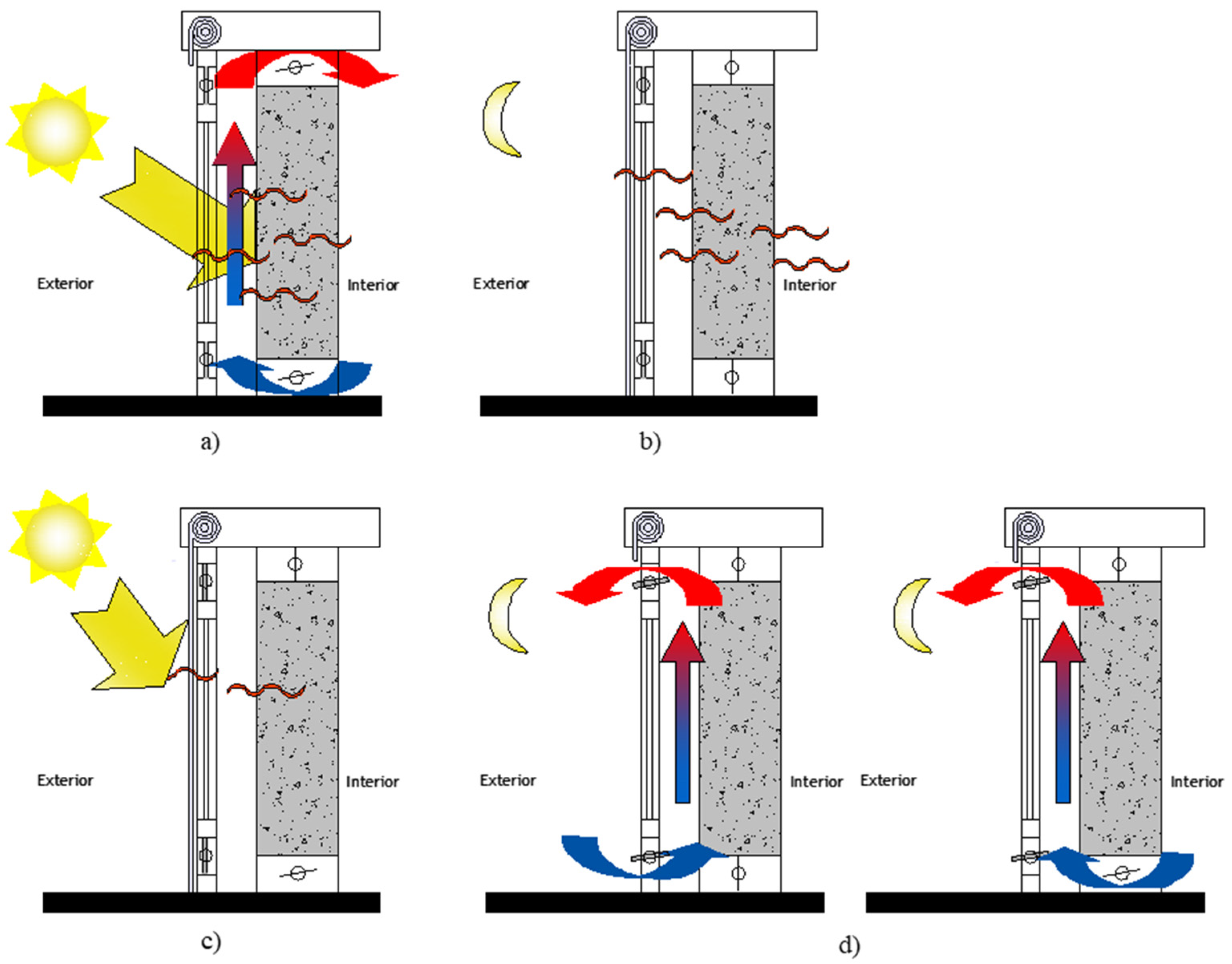
2. An Overview of the Trombe Wall Concept

The Trombe wall system is south-oriented to maximize its sun exposure, and is basically composed of a single massive wall, an air layer and a glazing outside. It is characterized by heat storage capacity that can be gradually released to the internal spaces by conduction, convection and radiation through the massive wall. In this case, the system can be defined as a Non-Ventilated Trombe Wall (NVTW) and constitutes the simplest solution of passive solar walls, characterized by a heat delay on heat transfer. A proper sizing of the NVTW can provide an amount of heat capable of heating the internal space throughout the night. Part of the heat generated in the air layer caused by the greenhouse effect is also lost to the outside through the glazing, depending on the thermal gradient. Thus, the higher the temperatures in the air space, the greater the heat losses. An external shading device should also be considered to minimize heat losses to the outside environment during winter night periods when outside temperatures decrease, and also eliminate overheating during summer.
The classical Trombe wall model, whose concept was patented by Morse in 1881 and developed and popularized in 1957 by Félix Trombe and Jacques Michel, features a massive wall with air vents, allowing the improvement of heat transfer by air convection, being defined as the Ventilated Trombe Wall (VTW). Air vents located at the bottom and at the top of the massive wall contribute to reducing heat losses to the outside environment. Heat transfer from the air layer to the internal space will also occur through the upper openings, while the cooler air will leave the internal space to the air layer by the lower openings, establishing an air movement by thermocirculation and eliminating the need for mechanical ventilation. Since air layer temperatures reach high values in the NVTW case, heat losses through the glazing tend to be higher. If ventilation is allowed, the amount of heat stored in the massive wall decreases, given the addition of heat transfer by air convection. Thus, the air vent management should be performed considering the local weather conditions and the required temperatures inside the building. Taking into consideration that the Trombe wall was initially designed to perform as a passive heating system, it is necessary to avoid overheating during summer periods. Besides the activation of an external shading or occlusion device, including air vents simultaneously in the massive wall and in the glazed surface, the Double Ventilated Trombe-Wall (DVTW), as in Figure 1, will facilitate the air layer’s cooling. An optimization of the Trombe wall design, as well as appropriate management of the air vents and shading devices, is crucial to improve the thermal performance and obtain the required comfortable temperature inside buildings. During winter day-time periods with high solar radiation intensity, air vents at the glazing surface and massive wall should be closed to create the air layer greenhouse effect and increase temperature values. Shading devices should not be considered, in order to maximize solar gains. The massive wall’s ventilation system should only be open when the temperature in the air layer is higher than the temperature inside the room and space heating is required (Figure 1a). During the night, air vents and shading devices should be closed to avoid heat losses from inside to the outside environment (Figure 1b). In summer, during the day, the ventilation system must remain closed and a shading device should be provided, taking into consideration that the more opaque the device is, the smaller the solar gains will be and the lighter its color, the greater the reflection of the incident solar radiation (Figure 1c). During the night, air vents at the glazing surface and shading devices should be open to promote the air layer cooling. In this case, a DVTW can also contribute to a building’s cross ventilation. The air vents at the bottom of the massive wall and the ones at the top of the glazing should be open, allowing the circulation of the hot air inside the building. Openings at the opposite north-oriented façade will allow the cross ventilation and the cooling of the internal spaces will be achieved (Figure 1d). In this case, the Trombe wall’s operation can be optimized for heating and cooling seasons [13,14,15], showing the crucial role of the ventilation system in the Trombe wall’s thermal performance.
Several studies, using experimental setups and simulation models, have been developed to analyze different configurations of Trombe walls and to optimize their thermal behavior. New concepts emerged in regard to the massive wall’s materials [16,17,18,19,20], the glazing type [14,21,22,23], the ventilation system [14,19,20,21,22,23,24,25,26] and the shading/occlusion devices [27,28]. Thermal insulation materials [29,30], phase change materials [31,32,33] and photovoltaic cells [15,34,35,36,37,38] have also been considered as components for the system’s improvement.
As mentioned before, the inclusion of air vents in the system plays an extremely important role in its thermal performance, given the additional heat flow by air convection that occurs in the air layer. Studies conducted in this field are essentially related to Trombe walls with air vents in the massive wall (VTW). A classical Trombe wall was analyzed under a high range of climate conditions, allowing researchers to establish a preliminary intercorrelation between the system’s thermal performance and the ventilation openings and shading devices’ operation modes. The results showed that opening or closing the air vents will influence the air layer and the massive wall temperature variation, and consequently, the temperature inside the room [39]. An optimization on the Trombe wall’s opening and closing models was also carried out using experimental research and numerical calculation [40]. It was concluded that the system should be opened 2–3 h after sunrise and closed 1 h before sunset. Another research work led to the conclusion that air velocity changes depending on the air vent’s location [41]. As mentioned above, when there are air vents, simultaneously, in the massive wall and in the glazing surface (DVTW), a Trombe wall’s performance can be optimized for heating and cooling seasons. In this context, a study was developed to increase the possibility of using Trombe walls in hot climates. Different ventilation system operating modes were proposed to reduce heat gains by conduction through the massive wall and to increase heat losses by ventilation processes [13].
Regarding the shading/occlusion devices, the effect of air gap occlusion on the Trombe wall’s thermal performance was analyzed for winter periods. A shading device was introduced in the air layer, with research concluding that using an occlusion device will minimize the convective heat losses in the air gap and prevent heat transfer by radiation to the outside environment [25]. The analysis of external shading devices is also required when more efficient solutions are needed to minimize the risk of overheating during the summer in climates with high solar radiation intensity. The Trombe wall’s thermal performance was analyzed during summer for Mediterranean climate conditions. The effect of screening devices, ventilation and occupancy was studied. The results showed that these factors significantly affect the Trombe wall’s thermal parameters during summer periods, namely the surface temperatures. A reduction of 1.4 °C in the surface temperatures is achieved when roller shutters are activated. It was also observed that the air velocity in the cavity is influenced by the temperature values in the air gap [42].
Concerning the massive wall, materials with high heat storage capacity should be applied and a surface that is dark in color will improve solar radiation absorption [17]. Thermal mass and thermal resistance of the storage wall are also decisive variables in the Trombe wall’s thermal behavior. It was also observed that indoor comfort is extremely linked to the type of storage wall material [21]. Furthermore, a research work on the analysis of the temperature fluctuation inside a room considering different massive wall materials and thicknesses allowed researchers to conclude that the thickness is important to the temperature fluctuation reduction. The solar energy heat gains obtained using a Trombe wall located in Turkey were analyzed for different materials in the massive wall [16]. Reinforced concrete, brick and autoclaved aerated concrete with different surface colors were taken into consideration. It was observed that annual heat gains varied between 26.9% and 9.7% for concrete, 20.5% and 7.1% for brick and 13.0% and 4.3% for aerated concrete, showing the influence of the massive wall’s thermal properties in heat transfer phenomena.
Given the specificities of this system and the need to be adjusted to different climatic conditions, building use and interior comfort requirements, among other factors, more research work should be performed to increase the knowledge of its thermal behavior facing different requests. The Trombe wall’s thermal behavior optimization without user intervention should also be considered as a way to encourage the integration of this passive solar system in building envelopes. In this context, a detailed analysis of the interconnection between the different parameters influencing the Trombe wall’s performance is still required.

3. Experimental Methodology

The Trombe wall’s thermal performance analysis was performed based on experimental work that has been developed by Briga-Sá et al. [20,39,42]. A test cell with a classical Trombe wall was subjected to the real climate conditions of the Portuguese city of Vila Real, characterized by high temperature variation and high solar radiation intensity, showing similarities with other Southern European countries. January and July are considered the coldest and the warmest months for this region. Solar radiation can achieve values around 950 MJ/m2 during July [42]. A detailed description of the exterior temperature and solar radiation intensity values for the measurement period considered in this research work can be found in previous study developed by Briga-Sá et al. [42].
The experimental device was designed, built, instrumented and monitored. The Trombe wall’s southern orientation and the minimization of the external obstacle’s effects were ensured in order to maximize the solar radiation’s contribution to heat gains.
The instrumentation and monitoring allowed the measurement of different parameters representative of the Trombe wall’s thermal behavior under dynamic conditions. Temperature values were registered at different points of the Trombe wall’s layers. Indoor and outdoor temperatures and solar radiation intensity were also acquired during the measurement period occurred between August and November [39,42] covering the cooling season and the transition to the heating season. The NVTW configuration was considered for a first period of 14 consecutive days from 20th September to 4th October while the VTW configuration was analyzed for a period of 35 consecutive days from 12th August to 15th September. In the research work here presented, some periods of this experimental measurement were chosen so a more detailed analysis about the temperature fluctuations could be performed. Data acquisition was made at time intervals of five minutes. The aspects taken into consideration during the different stages of the experimental work related to the test cell design, construction, instrumentation and monitoring will be described in more detail in the following sections. The Trombe wall’s construction details, such as geometry, materials, layer thicknesses and air vent configuration will be presented.
The acquired temperature values were analyzed in detail considering the influence of the air convection flow, depending on the air vent management and the thermal storage specificities of this passive solar system.
The obtained results constitute an important database for further defining an automation and control system of the Trombe wall avoiding user intervention. A detailed analysis will allow the establishment of an interconnecting relationship between the influencing factors of the Trombe wall’s thermal performance, such as outdoor climate conditions, materials’ storage capacity and system operating modes. Taking this into account, a first approach to define the automation and control algorithms of the Trombe wall’s operation can be carried out in order to achieve the required interior temperature of the test cell.

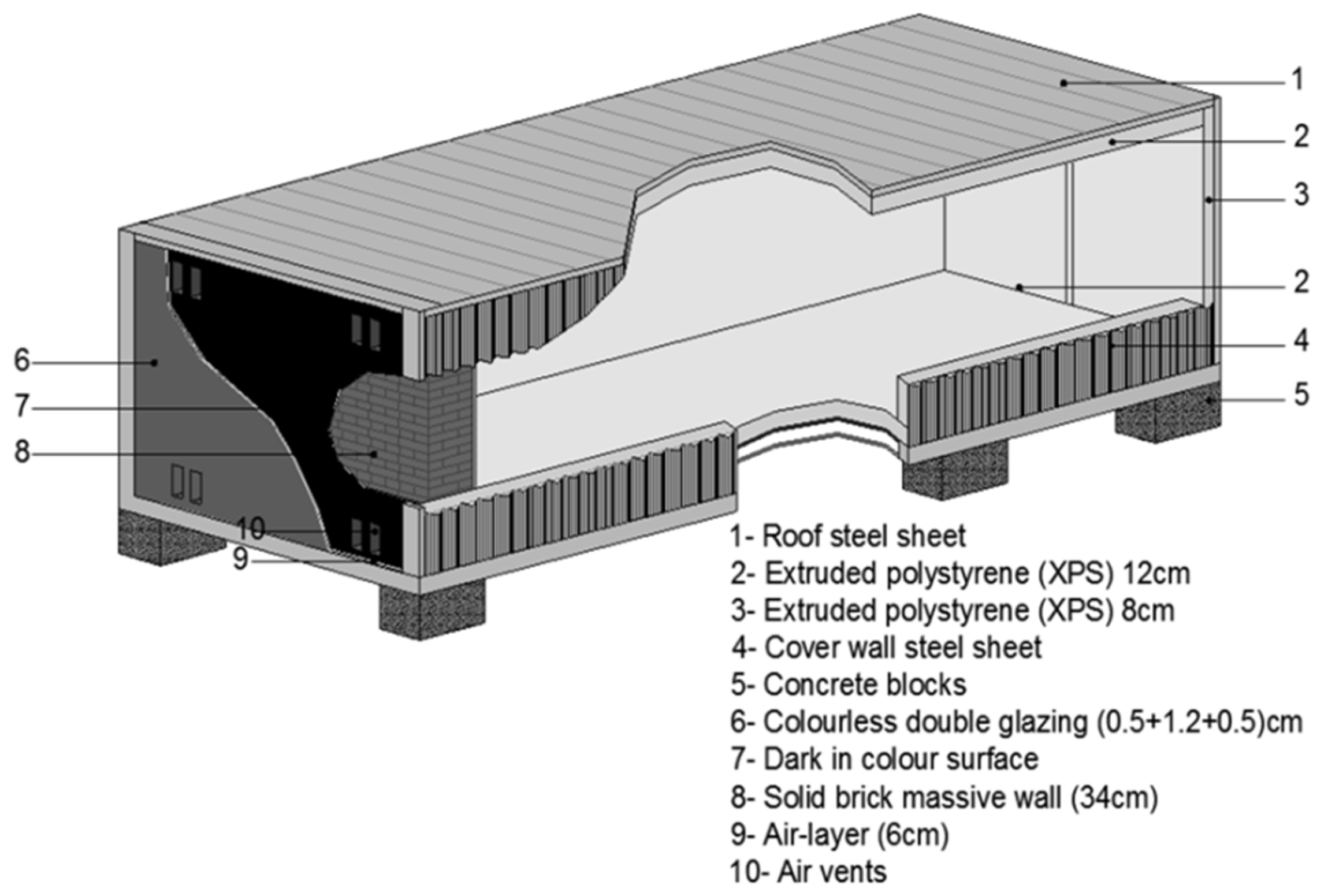
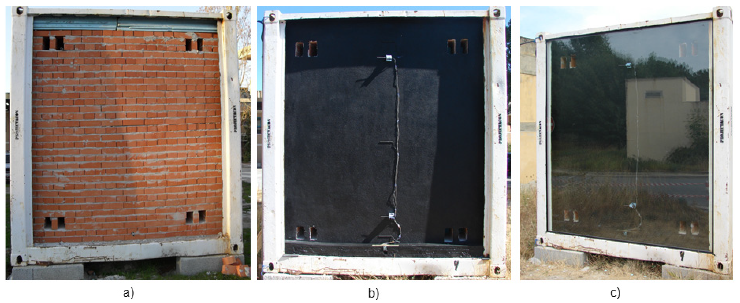
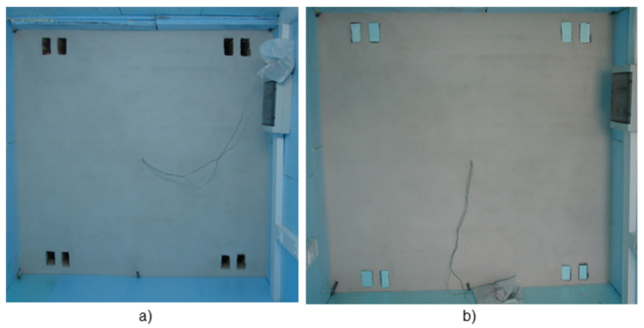
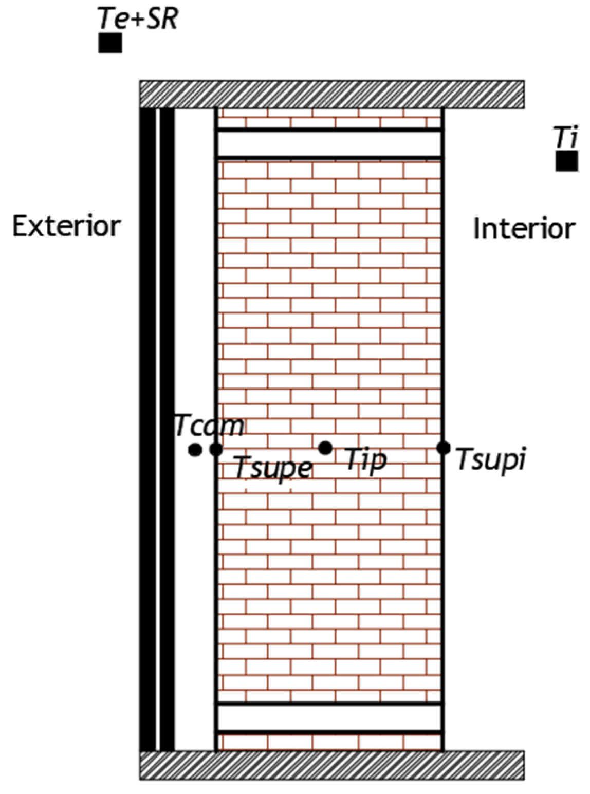
3.1. Test Cell and Trombe Wall Construction Details

A metallic container insulated with extruded polystyrene (XPS) was used to build the test cell (Figure 2). The container’s south façade was removed to allow the construction of the Trombe wall system, as shown in Figure 3. Thermal losses between the test cell and the soil were avoided by placing concrete blocks to support the structure and create a ventilated space. Heat gains and losses through the test cell were minimized according to the Portuguese thermal regulation requirements by applying thermal insulation in the inner surfaces of the remaining walls, floor and roof. XPS boards with 12 cm of thickness were placed on the floor and ceiling and 8 cm insulation boards were used for walls, achieving thermal transmission coefficient values of 0.43 W/m2 °C and 0.30 W/m2 °C, respectively. A test cell with 6 m (length) × 2.4 m (width) × 2.3 m (height), resulting in approximately 14 m2 of useful area and 33 m3 of volume was obtained [39,42]. The construction details of the experimental device used to the Trombe wall’s performance evaluation are similar to those required in PASSYS test cells used for the analysis of building components’ thermal behavior [43].
A classical Trombe wall system with an area of approximately 6 m2 was analyzed. The Trombe wall area is in accordance with the values reported in the literature, considering the average temperature of the heating season for the climate zone under study [44]. Therefore, the Trombe wall area is suitable for the room area, in this case simulated by a test cell. It was composed by a solid brick massive wall with 34 cm of thickness (Figure 3a), covered by mortar in both surfaces, an air layer with around 6 cm of thickness and a colorless double-glazed surface outside (Figure 3c). The massive wall external surface was colored black to enhance solar radiation intensity absorption (Figure 3b).
The ventilation system was guaranteed by four air vents at the top and four at the bottom of the massive wall, corresponding to approximately 2% of the Trombe wall’s area [40]. A maximum distance between the lower and upper air vents allowed increasing the heat flow by air convection. Covers made of XPS boards were used to close the air vents, as shown in Figure 4, defining two different operating modes of the system: the Non-ventilated Trombe wall (NVTW) when the covers were placed on, and the Ventilated Trombe wall (VTW) with no covers. The Trombe wall system also included an external white shutter outside to avoid thermal losses during winter night periods and overheating during summer. However, given that the aim of this research work is to analyze the influence of air vent management on the temperature fluctuation, no shading device was considered at this stage.

3.2. Instrumentation and Monitoring

The instrumentation and monitoring of the experimental device allowed a continuous acquisition of different parameters representative of the Trombe wall’s thermal performance under real weather conditions. Data was registered for periods of 5 min resulting from the average values collected every 30 s. Temperature sensors were placed in different points of the Trombe wall layers to measure the temperature fluctuation in the air layer (Tcam), in the massive wall external and internal surfaces (Tsupe and Tsupi, respectively) and also inside the massive wall (Tip). Solar radiation intensity (SR) and temperature (Te) were measured to register the outdoor conditions (Figure 5). Test cell interior temperature (Ti) was also acquired during the measurement period. A more detailed description of the used sensors is presented in Table 1. Given that the temperature sensors used during this experimental study only registered values up to 60 °C, an adjustment of the oscillation curves was performed using MATLAB whenever higher values were reached, as can be seen in Section 4.

3.3. Trombe Wall Operating Modes

The variables referred to previously were measured for the ventilated (VTW) and non-ventilated (NVTW) Trombe wall configurations to identify how these operating modes influence the heat transfer by conduction, convection and radiation through the massive wall and also by air convection through the air vents and, consequently, the temperature fluctuation in different points of the wall. The ventilation system was closed using covers made of XPS boards with 34 cm of thickness, Figure 4.
The air vents’ opening and closing was performed randomly as a preliminary analysis of the effect of different operating modes on the temperature values and no optimization was performed. As referred to previously, it was also considered that an external shutter was always open during the analyzed periods and no influence of its activation was considered. Table 2 presents a detailed description of the Trombe wall’s operating modes and the measurement periods selected to perform the detailed analysis.

4. Results and Discussion

In this section, the experimental results are analyzed and discussed in detail. Firstly, the analysis regarding the outdoor climate conditions will be presented. Then, the impact of solar radiation intensity and exterior temperature on the temperature inside the test cell is discussed and interconnected with the Trombe wall’s operating modes. The influence of the air vent management in the temperature fluctuation is analyzed for the VTW and NVTW cases.

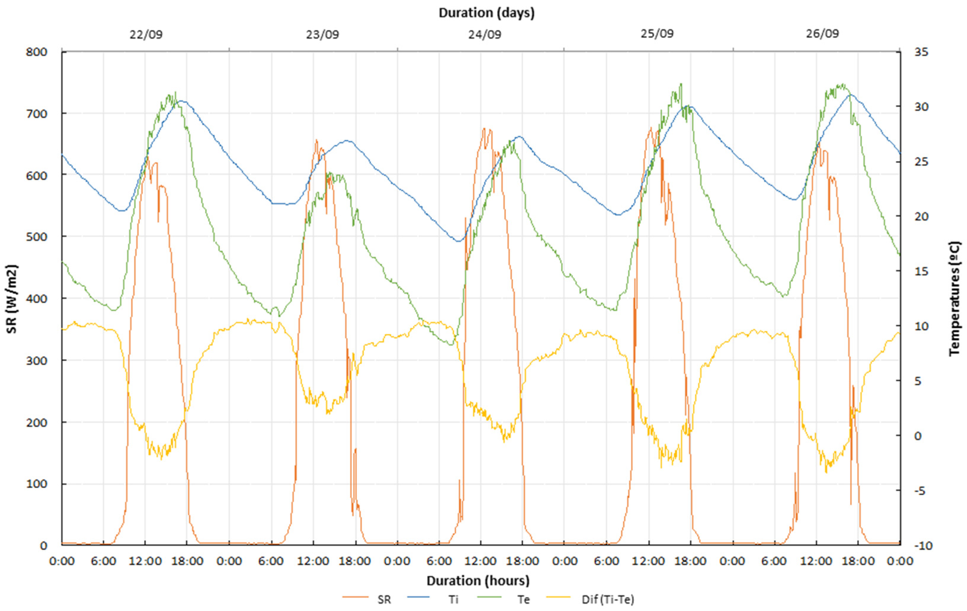
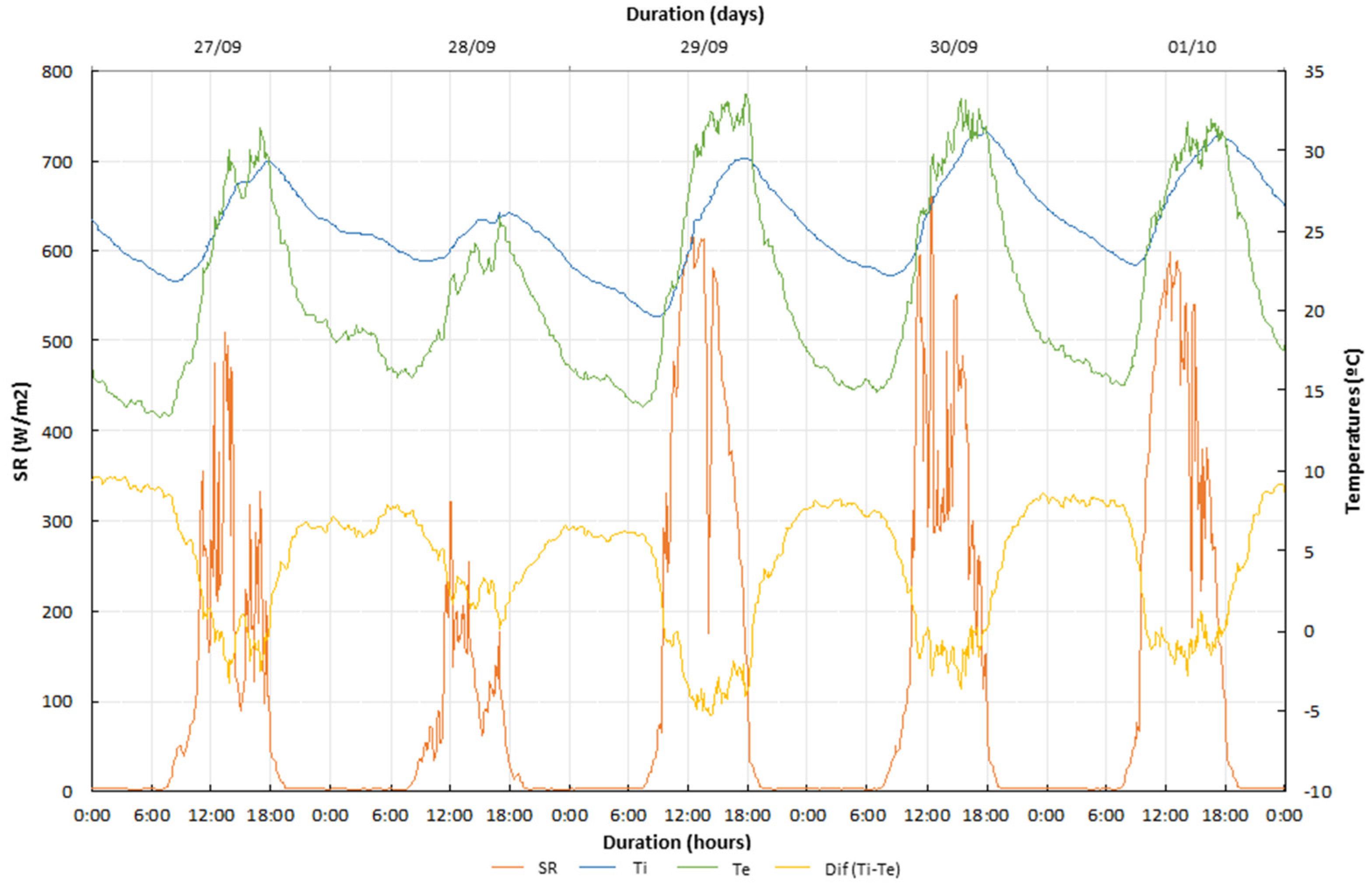
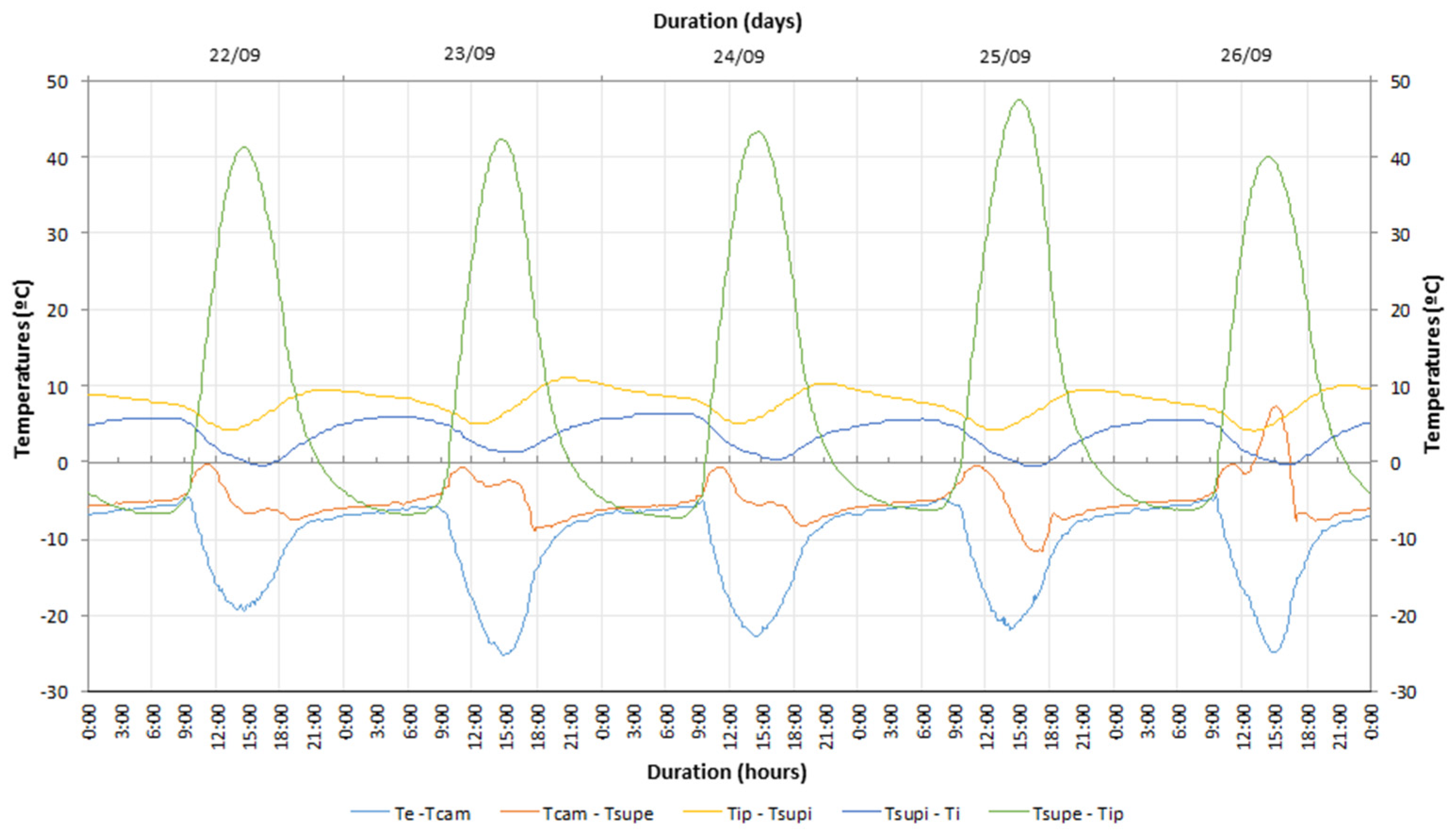
4.1. Non-Ventilated Trombe Wall (NVTW)

The NVTW configuration was considered for a first period of 14 consecutive days from 20th September to 4th October. For a better understanding of the system’s performance, two shorter periods of time were selected so a more detailed analysis could be performed. Periods with similar values of solar radiation intensity (SR) and exterior temperature (Te) were chosen. Although this selection is hampered by the variability and irregularity of the exterior climatic conditions, periods of more regular values and similar magnitude orders of SR and Te were chosen. Thus, in the NVTW case, the following was defined: a first period of 5 consecutive days, from 22nd September until 26th September, and a second period of 5 consecutive days, from 27th September until 1st October.

4.1.1. Indoor and Outdoor Climate Conditions

As referred to above, two measurement periods were selected to analyze the temperature fluctuations in the case of the NVTW configuration for different outdoor climate conditions. A preliminary analysis was carried out considering the direct impact of SR and Te variation in the temperature fluctuations inside the test cell.
During the first measurement period (Period 1), shown in Figure 6, solar radiation intensity presented a lower oscillation pattern compared to that observed during the second period (Period 2), shown in Figure 7, which is close to the heating season, usually characterized by a greater variability of SR values. Given that SR is a climate parameter that decisively influences the solar gains through the wall, its relation with Te and with the differential between indoor and outdoor environments temperatures, Dif (Ti-Te), requires special attention, justifying the detailed analysis performed in this study.
It can also be observed that that for similar SR oscillation curves, different Te values can be achieved, influencing Ti values, as can be seen when the 24th and the 25th September are compared (Figure 6). Although these days present similar SR oscillation patterns, lower Te values are verified on the 24th September, leading to a decrease in the test cell interior temperature. It can also be concluded that, for similar values of SR, a decrease of 62% in Te values correspond, on average, to a decrease of 30% in Ti values. Another observable aspect is that, on some days, when Te exceeds 30 °C, Ti presents lower values, while on days when Te presents values below 30 °C, the maximum temperature inside the test cell is always higher than the maximum value of Te. This situation may be due to the progressive storage capacity of the system that occurs over the days, influenced by the solar radiation and exterior temperature values’ variation, verified previously. It is also important to note that no external shading device was considered, which influences the heat transfer through the system. The storage capacity of the NVTW is verified during night periods based on the temperatures inside the test cell, which are always higher than the exterior temperatures. Considering that no ventilation is allowed through the air vents given that the XPS boards are placed on, the greenhouse effect created in the air layer during the day will lead to the massive wall’s heat storage and a heat delay to the test cell will occur. The heat transfer phenomena and the materials’ heat storage capacity can result in higher temperature values inside the test cell when compared with the ones obtained outside. Furthermore, given that no shading device is activated, an increase of heat losses from inside to outside environments is observed, which means that higher values of Ti can be achieved if the external shutter is closed. Analyzing Dif (Ti-Te) curves for the night periods, a reduction of 30% is obtained in Ti values compared to the maximum values achieved during the day. However, given that this measurement period corresponded to the cooling season, it can be considered that Ti values are acceptable as comfortable temperatures for this time of the year, establishing 25 °C as the reference temperature. Values above 20 °C are obtained during the night, which is satisfactory in the case of night occupancy buildings, such as residential buildings.
Figure 7 presents the results for Period 2 that correspond, as referred previously, to the transition between the cooling and the heating seasons and whose selection was based in the fact that, during this period of the year, greater oscillation occurs in the exterior climate conditions, which decisively influences the system’s performance, namely in regard to the temperature fluctuation. It is clear that the SR curve presents high oscillations and a response by the system to this instability is visible in the variation of Ti values, contrary to what occurs when a variation in Te values is verified.
Comparing the results for the two periods, it can be concluded that higher SR values during a long time led to higher solar gains through the Trombe wall and also to an increase of the interior temperature. For example, the lowest SR and Te values were measured on 28th September, leading to a less pronounced increase in the interior temperature than in the other days of the measurement periods. At 16:00, solar radiation decreases to values around 50 W/m2 and, consequently, a decrease in the interior temperature is observed. This situation may indicate that for radiation values with this magnitude order, the system contribution for the space heating is reduced. Although this behavior will be an advantage for the cooling season, it will not be for the heating one.
For both measurement periods, it can also be seen that Ti variation is less significant than Te and during the night Ti values always exceed Te values. This situation can be explained by the system ability to store and release heat gradually to the interior of the test cell. In the NVTW, heat transfer only occurs by the massive wall with no heat transfer by air convection through the ventilation openings, leading to a heat delay and to Ti values higher than Te. It is also important to refer that no occlusion device is used during this period, which is favorable for this time of the year, given that it will increase the heat losses to the external environment and reduce the interior temperatures.
These results allow us to conclude that, if this Trombe wall was introduced in the building envelope of a residential building, the interior temperature values would fulfil the comfort values required in the Portuguese thermal regulations. In the case of a building with daytime use, Ti values are not acceptable, revealing the need for using shading device during the day, as expected for this time of the year.

4.1.2. Temperature Fluctuation

An analysis of the temperature differential verified between the different layers allowed conclusions to be drawn about the influence of the exterior environment’s climate conditions and the Trombe wall’s design characteristics on the system’s thermal performance and its contribution to the indoor conditions. Temperature fluctuation also represents the greenhouse effect created in the air layer, the system heat storage capacity and the heat delay to the internal space. In Figure 8 and Figure 9, the temperature differential variation is presented for Period 1 and Period 2, respectively, and the effect of different outdoor conditions is reflected in the obtained results. The interconnection between the temperatures Te, Tcam, Tsupe, Tiw, Tsupi and Ti was established and the differentials (Te-Tcam), (Tcam-Tsupe), (Tsupe-Tip), (Tip-Tsupi) and (Tsupi-Ti) were calculated.
Figure 8 shows that the air layer temperature, Tcam, is higher than the exterior temperature, Te, achieving a differential that ranged between 20 °C and 25 °C during the day, due to the air layer heat storage and air vents closing. An outer surface that is painted dark in color increases the solar absorption and contributes to the achievement of higher Tcam values. In the night period, this differential decreased for 5 °C, independently of the maximum value reached during the day, proving the system’s heat storage capacity. Thus, and considering 5 °C as the minimum differential temperature, a temperature decrease between 60% and 80% can be estimated from day to night periods. Given the considered period of the year and the cooling demands, these are advantageous values to achieve indoor temperature comfort. However, if no XPS boards were placed on to close the ventilation system, air flow through the opening air vents will lead to higher heat losses from inside to outside the test cell and a decrease in temperature values will be obtained. These results also demonstrate the need to use an occlusion device during the heating season’s night periods in order to avoid heat losses.
Regarding the temperature differential (Tcam-Tsupe), it can be observed that the oscillation curve is less pronounced given that Tcam and Tsupe values are measured in the air layer characterized by the greenhouse effect occurrence. The negative sign of the differential reveals that higher values are obtained for the outer surface of the massive wall, whose black coating increases heat absorption and superficial temperatures. Tsupe presented values near Tcam around 12:00, which could be a result of the higher solar radiation intensity measured at this time of the day, as it possible to observe in Figure 8. The 26th September is the only day when this differential is positive. The analysis of Figure 8 shows that, during this period, besides the higher SR values, the exterior temperature achieved higher values when compared with the remaining days. These means that higher values of solar radiation, combined with higher values of exterior temperature, can contribute to the air layer’s temperature increase, leading to higher values that the ones obtained in the massive wall’s external surface.
During the night periods, similar values of the differentials (Te-Tcam) and (Tcam-Tsupe) are verified, leading to the conclusion that the differential (Te-Tcam) is almost double when compared to the differential (Tcam-Tsupe). It is, therefore, estimated heat losses between the air layer and the outside environment increase by 50% compared to the massive wall’s external surface, which is due to the heat storage capacity guaranteed by the massive wall’s material being painted black.
The curve of the temperature differential between the massive wall’s external surface and the interior of the massive wall (Tsupe-Tip) presents the highest positive values (Figure 8) reaching a differential of 47 °C during the day, given that Tsupe values are much higher that Tip values. This is due to the air layer’s greenhouse effect, the increasing heat absorption resulting from the massive wall’s black covering and the heat storage capacity of the solid brick masonry. Moreover, high SR values enhance solar gains and heat storage. At night, an inversion in the temperature range is visible. It can be estimated that Tip is 5 °C higher than Tsupe and 15 °C higher than Te, showing the material’s storage capacity and the gradual heat release by conduction through the massive wall. This delay is greater in the case of the NVTW given that no heat flow through the air vents is allowed.
The heat transfer can also be evaluated by the differential curves (Tip-Tsupi) and (Tsupi-Ti) development. In the first case, during the day, the temperature values inside the massive wall (Tip) are always higher than the ones reached at the massive wall’s internal surface (Tsupi). At night, the test cell cooling causes a differential increase of 50%, when compared to the day periods.
Analyzing the temperature differential between the interior of the test cell and the massive wall internal surface (Tsupi-Ti), similar values are registered during the day. The heat absorption, storage and release occurring during the day allow obtaining Tsupi values higher that Ti by 6–7 °C.
A similar analysis was carried out for the second period, Figure 9, corroborating the conclusions presented previously. More regular solar radiation intensity values increase the solar gains through the glazing surface, leading to the air layer and massive wall’s heating, resulting in a lower differential (Tcam-Tsupe). On the 30th September, the Trombe wall’s energy storage capacity is also noted. Despite the high oscillation of solar radiation, Tcam presented higher values than Tsupe, which can be explained by the high SR values during long periods and also by the achievement of high Te values that led to the massive wall’s heat storage increase. In the remaining days, this situation did not occur, since outdoor conditions became less favorable, characterized by a reduction and a greater oscillations of SR values. Regarding the remaining differential curves, a similar behavior is observed, although with lower values and higher oscillation patterns than the ones verified for Period 1, given the outdoor climate conditions’ instability.

4.2. Ventilated Trombe Wall (VTW)

The VTW configuration was considered for a period of 35 consecutive days from 12th August to 15th September and two smaller periods were selected for a more detailed analysis: a first period of 5 consecutive days, from the 19th August until the 23th August, and a second period of 5 consecutive days, from the 5th September until the 9th September.

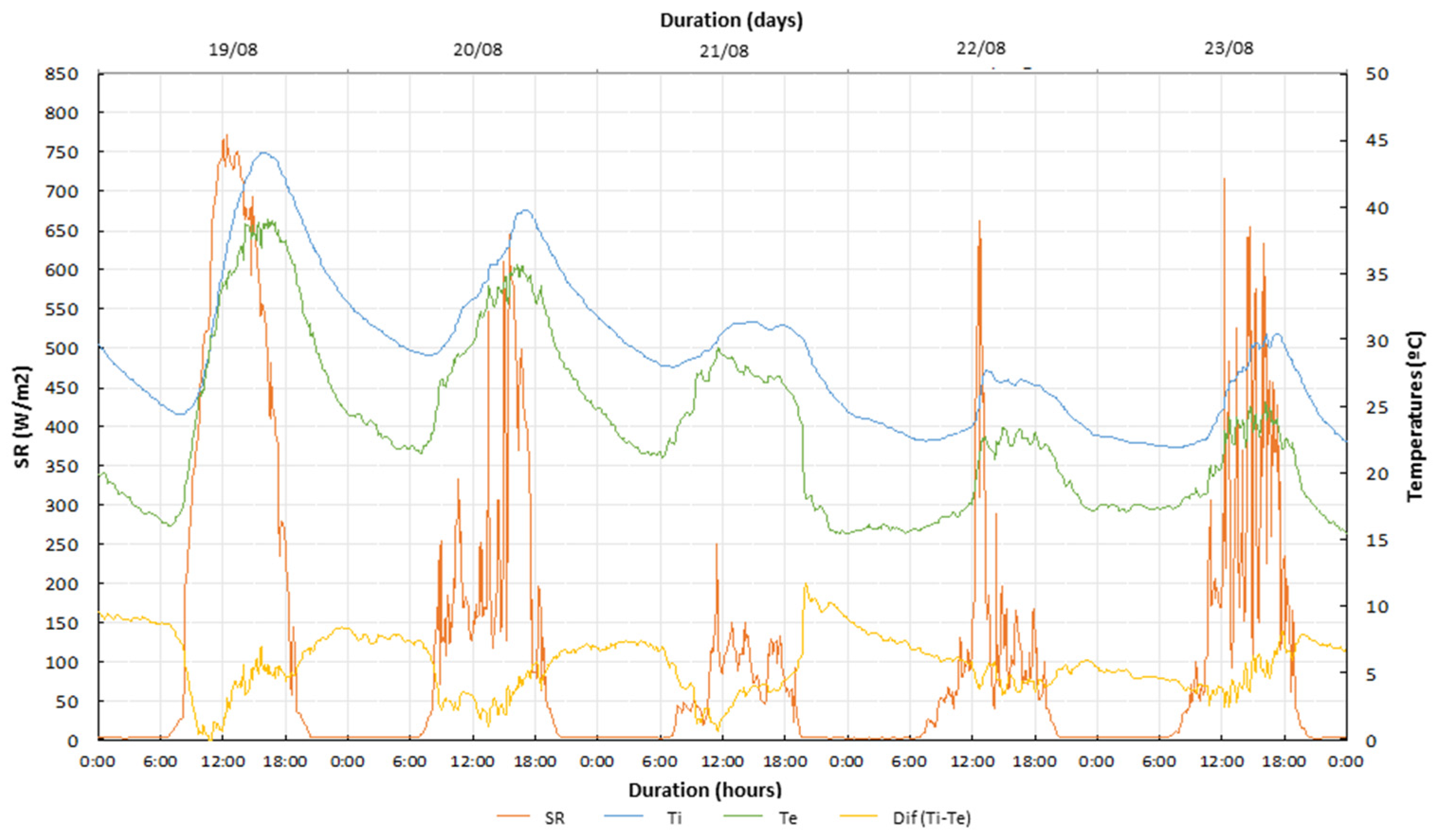
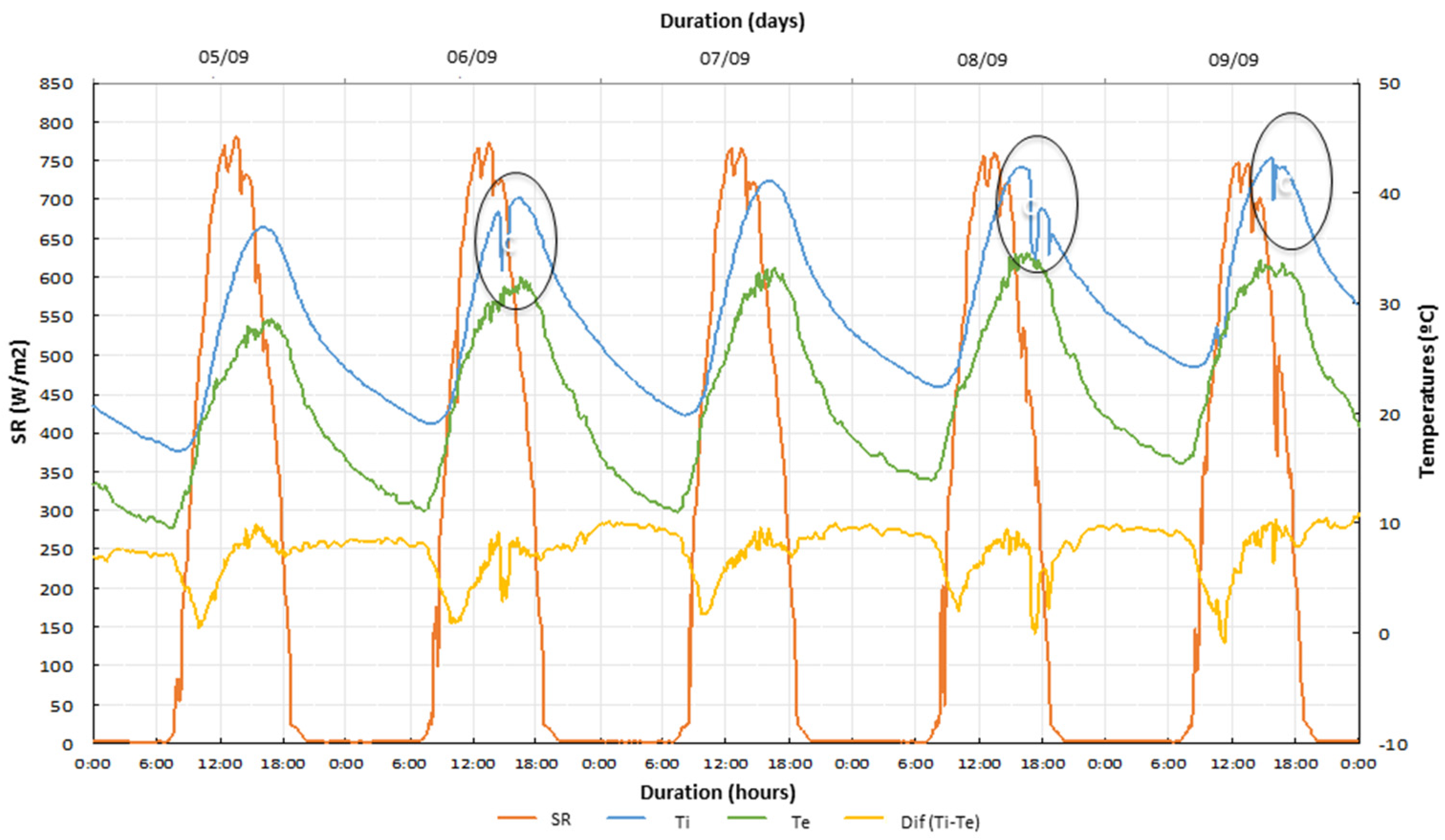
4.2.1. Indoor and Outdoor Climate Conditions

Figure 10 and Figure 11 represent the acquired values of solar radiation, exterior and interior temperatures and also the differential between those, for the measurement periods referred to above. Comparing both periods, more unstable conditions are verified in Period 1 for SR and Te values. Once again, it is noticeable that the longer the maximum solar radiation values last, the better the Trombe wall’s thermal performance, which can be confirmed by comparing the 19th August with the remaining days, regarding the temperature variation curves inside the test cell, Ti. A more irregular variation of SR values leads to the Ti decrease.
As an example, analyzing the 21st and the 22nd of August, it can be concluded that, although similar values of SR are registered, an increase of 12.5% is verified for Ti values on the 21st, while an increase of 22% was verified on the 22nd. In the case of a ventilated system 24 h a day, heat losses to the outside environment are accentuated when the outside temperatures decrease, as is visible during night periods. Furthermore, heat storage capacity is minimized when heat transfer by air convection through the air vents is allowed, meaning that changes in the outdoor conditions are reflected more quickly in the interior temperatures. During Period 1, the variability of solar radiation intensity leads to a decrease of 42% in Te values during the day-night transition, corresponding to a decrease of 33% in Ti values. Given the instability of SR and Te values, higher oscillations are verified in (Ti-Te) differential curves during the night, varying between 6 °C and 11 °C.
As referred before, Period 2 (Figure 11) is characterized by more stability in the outdoor conditions compared to Period 1, allowing a better understanding of the VTW.
During the night, a Te reduction around 56–65% corresponds to a decrease of Ti in 42–52% in the case of VTW.
These results lead to the conclusion that the VTW operation allows, during the night, a reduction of around 50% in Ti values compared to the maximum reached during the day, considering that the temperature outside, Te, reached day-time and night-time values of 35 °C and 12 °C, respectively. Regarding (Ti-Te) curve, it reached smaller differential values during the morning and the highest ones during the night. It is also important to mention that the variations identified with an oval mark in Figure 11 correspond to instants when the test cell door was opened to check the test conditions, not influencing the results analysis.

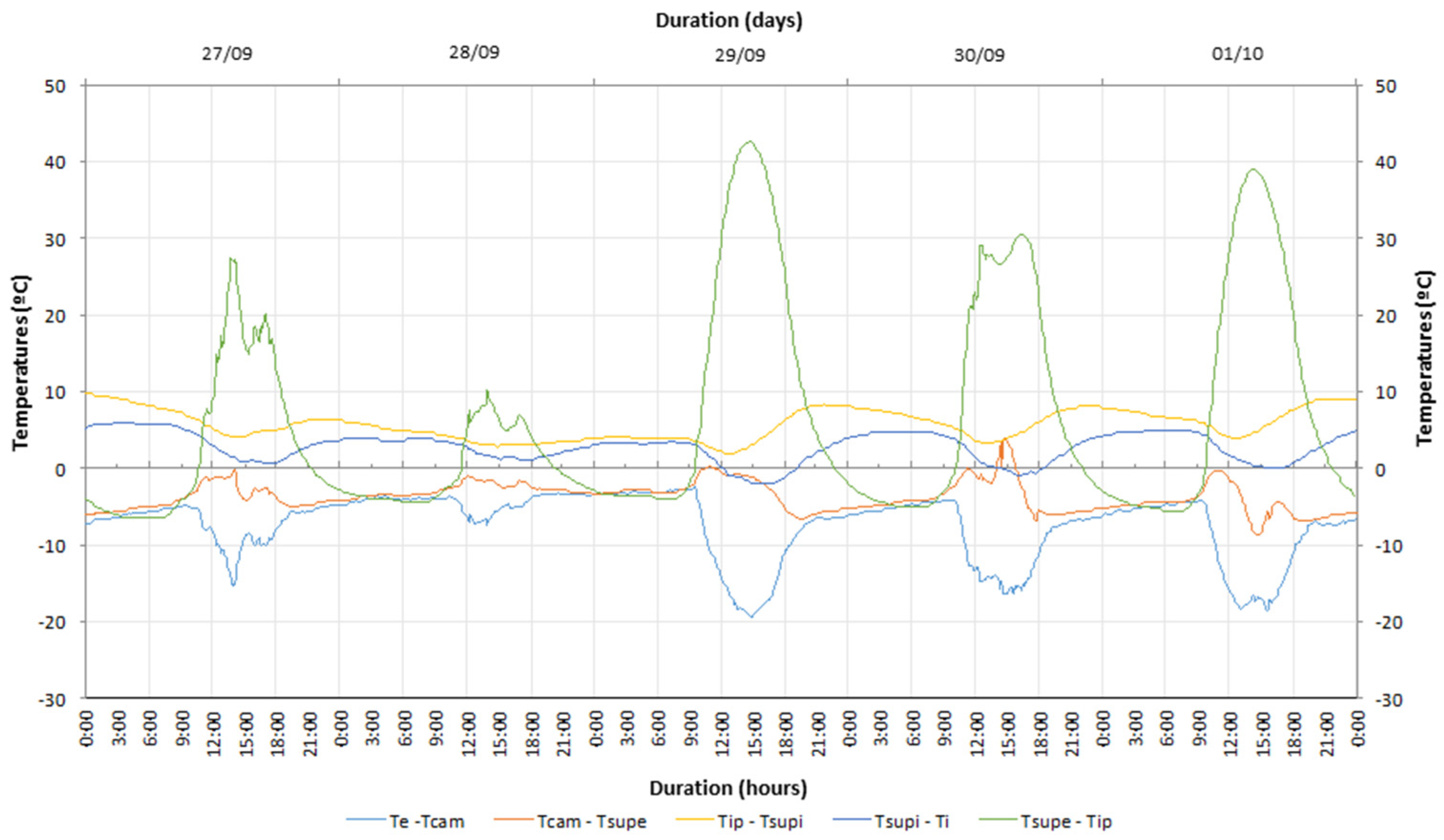
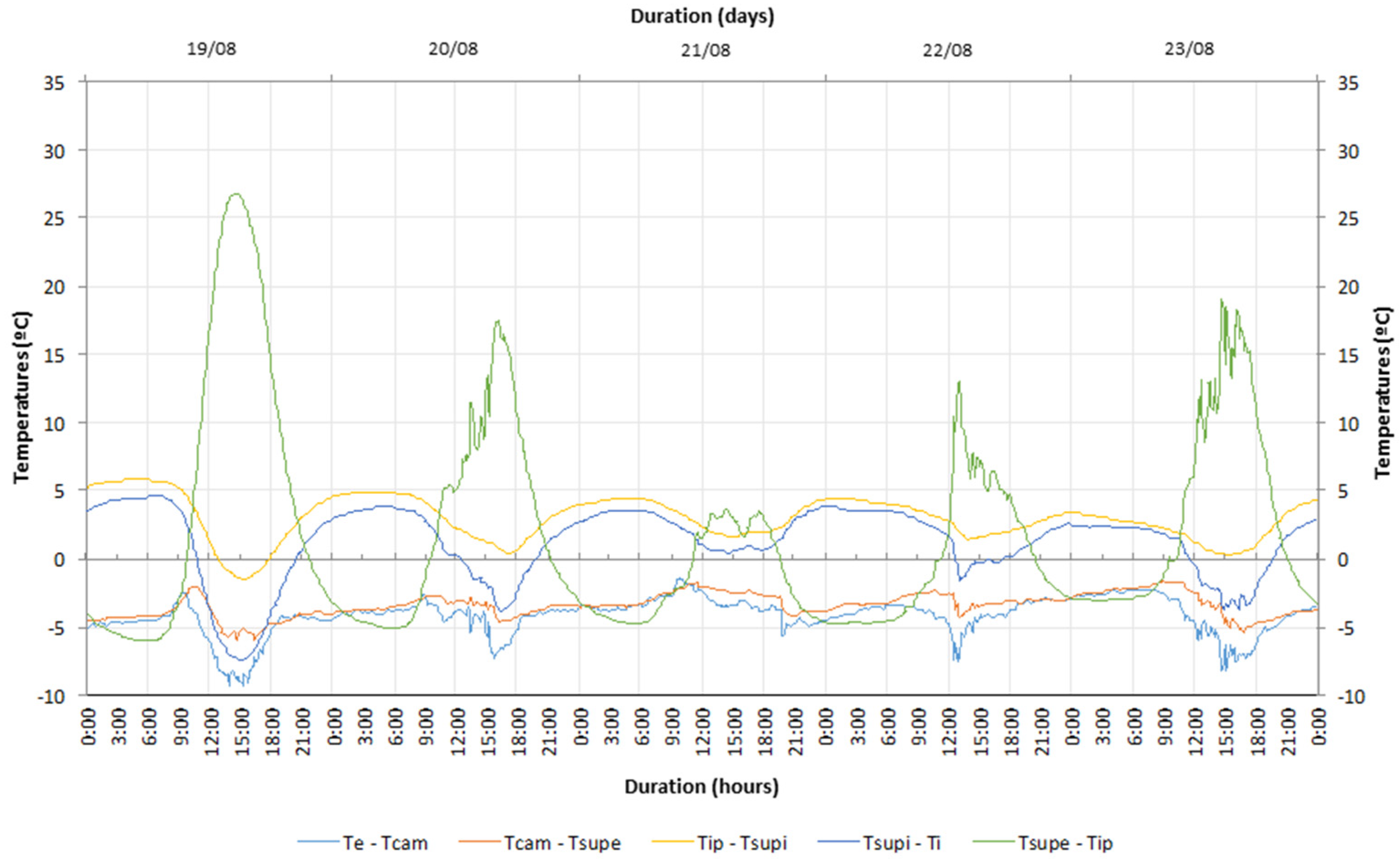
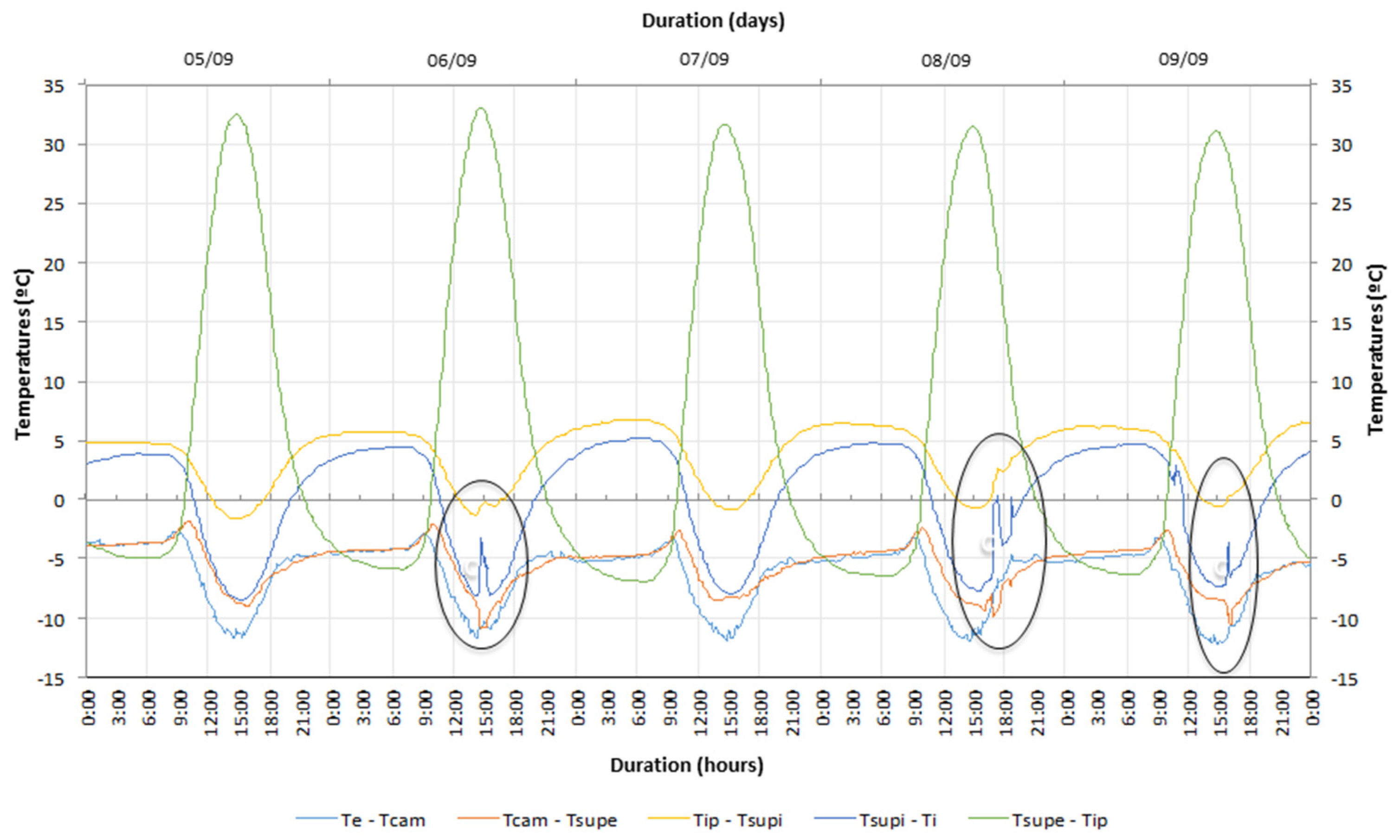
4.2.2. Temperature Fluctuation

Performing the analysis of the differential curve (Te-Tcam) (Figure 12), negative values are observed, as shown in Figure 8 and Figure 9 referring to NVTW. This is an expected situation because, although air circulation through the openings is allowed 24 h a day, the temperature in the air layer tends to present higher values given the heat storage phenomenon occurring in the space between the glazing surface and the brick masonry wall. During the day, it is well known that solar radiation intensity causes an increasing differential, as proved by the negative peaks presented by the (Te-Tcam) curve. In the night period, the negative differential varies between 3 and 4 °C, indicating an air layer cooling capacity greater than that verified for the NVTW.
Regarding the (Tcam-Tsupe) curve, a negative differential is also observed due to the higher values obtained in the outer massive wall surface. Both (Te-Tcam) and (Tcam-Tsupe) differentials present almost coincident curves during the night period, tending to zero in the absence of solar radiation during the day. However, when comparing these results with the ones for the NVTW configuration, placing the XPS boards leads to a greater distance between those curves given that air convection movement by air vents is prevented.
Comparing two days of the NVTW and the VTW periods, with similar solar radiation conditions (24th September and 19th August), it can be concluded that the NVTW system obtains a differential of around 43 °C between the massive wall outer surface and the interior of the wall (Tsupe-Tip), while the VTW system only allows a differential of 27 °C. These results reflect the occurrence of heat transfer by air convection through the air vents, reducing greenhouse effect, solar absorption and heat storage in the massive wall.
Although the differential curves (Tip-Tsupi) and (Tsupi-Ti) present identical behavior, there is a positive differential at night, indicating that the massive wall presents higher temperatures than the air temperature inside the test cell. The curves’ development obtained during the day is influenced by the air flow through the massive wall ventilation system, allowing faster heating of the indoor environment than that verified in the NVTW case.
Figure 13 presents the obtained values for Period 2. As mentioned before, an oval mark corresponds to an instant when the test cell door was opened to check the test conditions, not influencing the results analysis. Concerning the temperature differential between the exterior and the air layer, (Te-Tcam), negative values are obtained, as was already verified in previous periods. During the day, Tcam can be higher by 12 °C than Te when air vents are open.
A fact that has been verified throughout the analysis carried out is that, during the night, the differential (Te-Tcam) is similar to the differential (Tcam-Tsupe), indicating that the glazing delays the heat transfer from the air layer to the outside. If this situation had not occurred, the difference between Te and Tcam would be lower than the difference between Tcam and Tsupe.
The curve (Tsupi-Ti) presents a behavior totally different from that verified in the NVTW case, presenting negative values during the entire measurement period, showing that, during the night, higher values are obtained inside the massive wall than the ones verified at the inner surface, and so heat transfer will take place from inside to outside of the wall, due to the heat delay that occurs during the day. During the day, Tip and Ti present similar values while during the night a delay of 6/7 °C is observed, thus reflecting a cooling capacity greater than 50% when compared to NVTW.
The analysis carried for (Tsupi-Ti) curve shows that the interior of the test cell also undergoes significant heating conditions during the day, being able to equal the differential between (Tcam-Tsupe). During the night, this is converted into a positive 6 °C differential due to heat losses occurring to the outside and heat irradiation from the massive wall.
Comparing the ventilated and non-ventilated systems, the differential (Tip-Tsupi) is around 5 °C during the night and 0 °C during the day for the NVTW, being 5 °C and −7 °C, respectively, for the VTW case. These results clearly show the impact of air ventilation in the Trombe wall’s thermal behavior. In the first situation, heat transfer only occurs through the massive wall while in the second one air circulation by convention decisively influences a faster heating of the indoor environment. Thus, the impact of heat solar gains is felt more quickly in the values of Ti in the VTW, while in the case of NVTW, the temperature fluctuations are dependent on the massive wall’s heat storage capacity and the consequent heat delay transfer to inside the test cell.

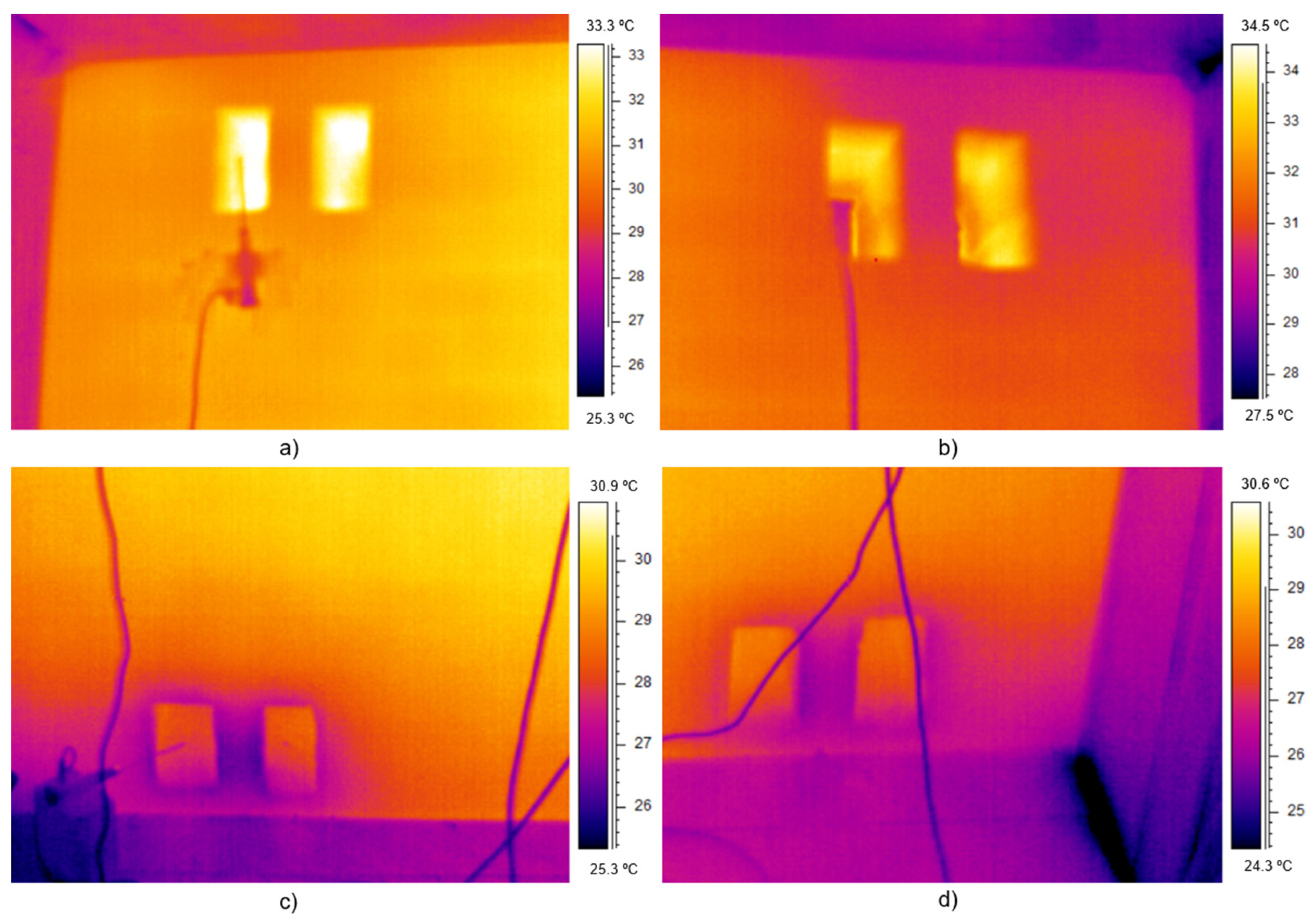
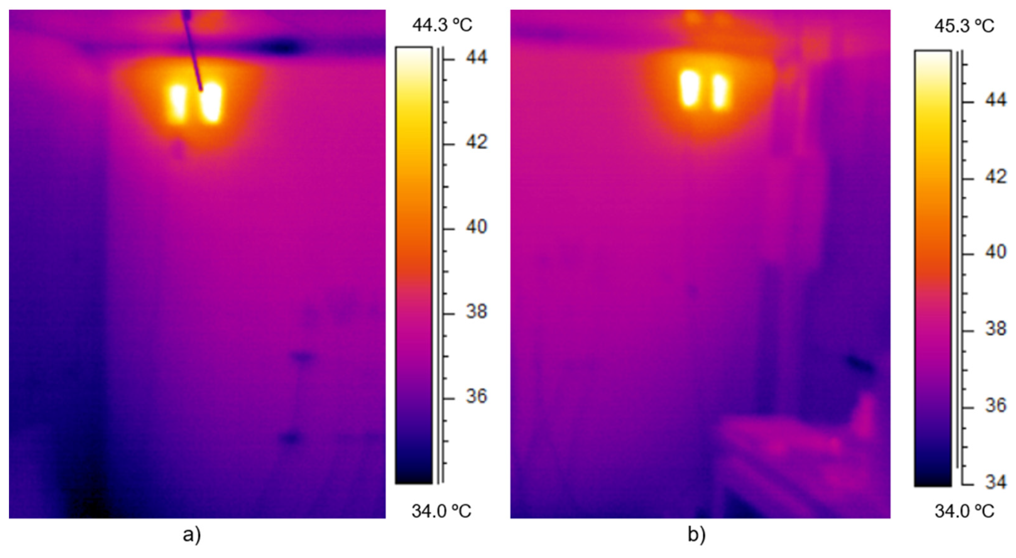
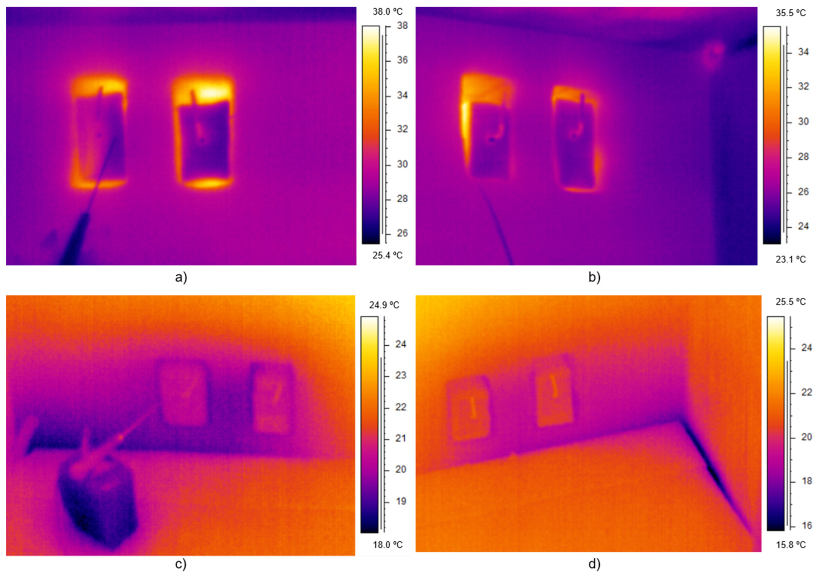
4.3. Thermographic Analysis

A thermographic analysis was also added to discuss temperature fluctuation near the air vents. Various thermograms were registered for the VTW and NVTW operating systems allowing identification of the influence of the air vent management on the inner surface temperature variation for different periods of the day. It is observed that the temperatures ranged between the upper and lower air vents and decreased when the XPS boards were placed on. Thermograms registered at 9:30 a.m. on 14th September, presented in Figure 14, show the temperature variation in the surrounding areas of the lower and upper air vents when they are open (VTW). Similar values are obtained for the four air vents at the top of the massive wall, achieving a maximum value of 34 °C at the air vents and a decrease to the minimum value of 27 °C in the surrounding areas registered by the thermographic images (Figure 14a,b). A decrease of 3 °C is verified at the bottom air vents and 4 °C at the surrounding areas (Figure 14c,d). In this case, heat transfer by air convection through the ventilation system is highlighted and prevailing, allowing faster heating of the test cell and uniformizing the inner surface temperature values, Tsupi, which justifies the reduced temperature range between the air vents at the top and at the bottom. In addition, this measurement was carried out during the morning, characterized by lower values of SR, demonstrating that the high values obtained are due to the system’s heat absorption and retention capacity over time when subject to days of favorable solar radiation intensity conditions.
At the same day, around 7:30 p.m., two more images were taken to characterize Tsupe fluctuation, covering the upper air vents and also the base of the massive wall, Figure 15a,b. Maximum values of 45 °C and 44 °C were registered at the right and left upper air vents, respectively, showing an increase of more than 10 °C compared to the morning period. At the base of the massive wall, minimum values around 34 °C are achieved, which can be considered high temperature values besides the decrease of around 10 °C from the top of the wall.
The influence of placing the XPS boards to cover the air vents was analyzed for the 19th September of the NVTW period, Figure 16. Thermograms registered at 11:00 a.m. showed maximum values of 38 °C and 35.5 °C at the upper air vents, at the left and at the right side, respectively. As can be observed by the images, the boards do not cover all the air vents, allowing air infiltration which corresponds to the maximum values previously referred and causes this temperature differential at the air vents. However, it can also be noted that when XPS boards cover the air vents, similar values are obtained at those areas and at the surrounding ones, achieving a decrease of around 27 °C, which are lower values that the ones obtained for the VTW, as expected. Regarding the lower air vents, temperatures decrease for values around 19 °C for the air vents at the left side and around 21 °C for the ones located at the right side of the massive wall, being much lower values compared to the ones obtained for the VTW situation.
This comparative thermographic analysis clearly identifies the increase of the inner surface temperatures when the massive wall is ventilated. Furthermore, these values increase throughout the day due to the gradual heat storage, with greater significance for days with higher values of solar radiation and higher prevalence. The surface temperature values significantly decrease in the NVTW case since heat transfer through the air vents is avoided, occurring only through the brick masonry wall and being dependent on the greater or lesser storage capacity of the massive wall’s materials.

4.4. An Approach for Defining an Automation and Control Algorithm

The results presented above can be used for a first approach to define the automation and control algorithm to guarantee that no user intervention is needed for the Trombe wall’s operation. As shown above, the Trombe wall’s efficiency is directly related to the air vent management and also to the shading device activation when heat losses and overheating periods are unwanted. The results corroborated that SR is a decisive variable on this passive solar system behavior. As such, solar radiation intensity was a preliminary influencing parameter to be considered in the algorithm’s definition. Taking this into account, two scenarios can be proposed (Table 3), one for the heating season (Scenario 1) and one for the cooling season (Scenario 2). The SR values selected for the algorithm definition are based on the temperature fluctuations obtained for the NVTW and VTW configurations, with particular attention to the air layer temperatures and the temperature inside the test cell. It is intended with the proposed operating intervals to present a first approach to predict the solar radiation influence in obtaining the required interior comfort temperatures.
Analyzing the NVTW configuration, a code for opening/closing the ventilation system can be proposed. During the heating season, the air vents should be open when the solar radiation values exceed 100 W/m2. The external shutter should also be open in order to maximize solar heat gains. For values of SR lower that 50 W/m2 the XPS boards should be placed on to avoid heat losses by air convection flow and the shading device should be also activated. Thus, the massive wall’s heat storage can be improved and a gradual heat release can contribute to indoor heating during day periods and to achieving thermal comfort during the night. If a SR sensor is included in the monitoring and control of the system behavior, maximizing solar gains will lead to higher indoor temperature values.
Considering the results previously analyzed for the VTW configuration, XPS covers should be placed on during winter day periods to avoid overheating and should be removed during the night to allow air flow through the air vents, leading to the cooling of the air layer and the possibility of cross ventilation. An external shading device should be closed during day periods and open during the night to allow heat transfer from the inside to the outside environments. Therefore, it is proposed to close the system when SR equals or exceeds 50 W/m2 and a system opening is suggested when SR falls below 20 W/m2.

5. Conclusions

The Trombe wall is a passive solar system of indirect gain that uses a renewable source to improve a building’s energy efficiency by reducing heating demands. Its integration in a building envelope in an autonomous way, without the user’s intervention, requires prior knowledge of its performance under different outdoor climate conditions and for different operating modes. This work consisted of a detailed analysis on the temperature fluctuation in the Trombe wall’s layers and its influence on the interior temperature for the NVTW and VTW cases under real climate conditions. It was thus possible to observe the influence of the air convection flow through the massive wall’s air vents and the system’s heat storage capacity, as well as the need to provide a shading/occlusion device.
Regarding to the NVTW, it was concluded that for similar values of SR, a decrease of 62% in Te values corresponds, on average, to a decrease of 30% in Ti values. It was also estimated that heat losses between the air layer and the outside environment increase 50% compared to the massive wall’s external surface, which is due to the heat storage capacity guaranteed by the massive wall material covered with a black painting mortar. It was also concluded that higher SR values during a long time led to higher solar gains through the Trombe wall and to an increase of Ti values. Thus, a progressive heat storage capacity is observed when regular values of solar radiation intensity are achieved during long periods of time. Values of Ti above 20 °C were verified during night periods, which can be considered satisfactory in the case of night occupancy buildings, such as residential ones. In the case of a building with daytime use, Ti values are not acceptable, revealing the need for using a shading device during the day, as expected for cooling season periods.
Regarding the VTW, it is noticeable that the longer the maximum solar radiation values last, the better the Trombe wall’s thermal performance. Furthermore, heat storage capacity is minimized when heat transfer by air convection through the air vents is allowed, meaning that changes in the outdoor conditions are reflected more quickly in the interior temperatures. During the night, a Te reduction around 56–65% corresponds to a decrease of Ti in 42–52%. When the air vents are open, the system allows a reduction of around 50% in Ti values compared to the maximum reached during the day.
Comparing two days with similar SR conditions for NVTW and VTW configurations, it was verified that the NVTW system obtains a differential of around 43 °C between Tsupe and Tip, while the VTW system only allows a differential of 27 °C. These results reflect the occurrence of heat transfer by air convection through the air vents, reducing the greenhouse effect, solar absorption and heat storage in the massive wall. An air layer cooling of about 50% can be achieved in the VTW case compared to NVTW operation.
These results allowed a first approach to define the functioning algorithm of the Trombe wall’s automation system, considering as decisive variable the solar radiation. Through the detailed analysis carried out, it was concluded that air vents and external shading device should be open when SR exceeds values of 100 W/m2 and closed for values of 50 W/m2 to obtain at least 20 °C inside the room. For the cooling season, Trombe wall heat gains have to be avoided and so, during the day, the air vents should be closed and the external shutter activated. At night, both systems should be open in order to dissipate the energy stored during the day and contribute to the cross ventilation. This cooling strategy will guarantee summer temperatures around 25 °C inside the building. According to the results, for this time of the year, closing the system for SR equal or higher than 50 W/m2 was proposed, while for values lower than 20 W/m2 the system’s opening was suggested.
More studies are currently under development by the research team in order to verify the real impact of this and other algorithms on the Trombe wall’s thermal performance optimization regarding its automation and control as a way to encourage the effective application of this passive solar system as an eco-efficient solution in buildings envelope.

Author Contributions

Conceptualization, A.B.-S.; methodology, A.B.-S., A.P., J.-C.L. and J.B.-C.; results analysis and discussion, A.B.-S., J.B.-C. and L.F.; writing—original draft preparation, A.B.-S.; writing—review and editing, A.B.-S. All authors have read and agreed to the published version of the manuscript.

Funding

This research received no external funding.

Data Availability Statement

Not applicable.

Conflicts of Interest

The authors declare no conflict of interest.

References

  1. European Commission. Energy Efficiency: New EU Rules for Buildings and Homes. 2018. Available online: https://www.europarl.europa.eu/news/en/headlines/economy/20180328STO00750/energy-efficiency-new-eu-rules-for-buildings-and-homes. (accessed on June 2021).
  2. Official Journal of The European Union. Directive 2010/31/EU of the European Parliament and of the Council of 19 May 2010 on the Energy Performance of Buildings. 2010. Available online: https://eur-lex.europa.eu/eli/dir/2010/31/oj (accessed on June 2021).
  3. Official Journal of The European Union. Directive 2012/27/EU of the European Parliament and of the Council of 25 October 2012 on Energy Efficiency, Amending Directives 2009/125/EC and 2010/30/EU and repealing Directives 2004/8/EC and 2006/32/EC Text with EEA Relevance. 2012. Available online: http://data.europa.eu/eli/dir/2012/27/oj (accessed on June 2021).
  4. Official Journal of The European Union. Directive (EU) 2018/844 of the European Parliament and of the Council of 30 May 2018 amending Directive 2010/31/EU on the Energy Performance of Buildings and Directive 2012/27/EU on Energy Efficiency (Text with EEA Relevance). 2018. Available online: http://data.europa.eu/eli/dir/2018/844/oj (accessed on June 2021).
  5. European Commission. 2020 Climate & Energy Package. 2020. Available online: https://ec.europa.eu/clima/policies/strategies/2020_en#tab-0-0 (accessed on June 2021).
  6. European Commission. The European Green Deal, Brussels, 11 December 2019. Available online: https://ec.europa.eu/info/sites/info/files/european-green-deal-communication_en.pdf (accessed on June 2021).
  7. Fernández-González, A. Analysis of the Thermal Performance and Comfort Conditions Produced by Five Different Passive Solar Heating Strategies in the United States Midwest. Sol. Energy 2007, 81, 581–593. [Google Scholar] [CrossRef]
  8. Raman, P.; Mande, S.; Kishore, V. A passive solar system for thermal comfort conditioning of buildings in composite climates. Sol. Energy 2001, 70, 319–329. [Google Scholar] [CrossRef]
  9. Burek, S.A.M.; Habeb, A. Air flow and thermal efficiency characteristics in solar chimneys and Trombe walls. Energy Build. 2007, 39, 128–135. [Google Scholar] [CrossRef]
  10. Balaras, C.A. The Role of Thermal Mass on the Cooling Load of Buildings. An Overview of Computational Methods. Energy Build. 1996, 24, 1–10. [Google Scholar] [CrossRef]
  11. Zhu, L.; Hurt, R.; Correia, D.; Boehm, R. Detailed Energy Saving Performance Analyses on Thermal Mass Walls Demonstrated in a Zero Energy House. Energy Build. 2009, 41, 303–310. [Google Scholar] [CrossRef]
  12. Hassanain, A.A.; Hokam, E.M.; Mallick, T.K. Effect of Solar Storage Wall on the Passive Solar Heating Constructions. Energy Build. 2010, 43, 737–747. [Google Scholar] [CrossRef]
  13. Ruiz, Á.; Salmerón, J.; González, R.; Álvarez, S. A calculation model for Trombe walls and its use as a passive cooling. In Proceedings of the International Conference “Passive and Low Energy Cooling for the Built Environment”, Santorini, Greece, 19–21 May 2005; pp. 365–369. [Google Scholar]
  14. Gan, G. A parametric study of Trombe wall for passive cooling of buildings. Energy Build. 1998, 27, 37–43. [Google Scholar] [CrossRef]
  15. Jie, J.; Hua, Y.; Gang, P.; Bin, J.; Wei, H. Study of PV-Trombe wall assisted with DC fan. Build. Environ. 2008, 42, 3529–3539. [Google Scholar] [CrossRef]
  16. Özbalta, T.; Kartal, S. Heat gain through Trombe wall using solar energy in acold region of Turkey. Sci. Res. Essays 2010, 5, 2768–2778. [Google Scholar]
  17. Nwachukwu, N.P.; Okonkwo, W.I. Effect of an absorptive coating on solar energy storage in a Trombe wall system. Energy Build. 2007, 40, 371–374. [Google Scholar] [CrossRef]
  18. Fang, X.; Li, Y. Numerical simulation and sensitivity analysis of lattice passive solar heating walls. Build. Environ. 2000, 69, 55–66. [Google Scholar] [CrossRef]
  19. Chen, W.; Liu, W. Numerical analysis of heat transfer in a passive solar composite wall with porous absorber. Appl. Therm. Eng. 2008, 28, 1251–1258. [Google Scholar] [CrossRef]
  20. Sá, A.B.; Martins, A.; Boaventura-Cunha, J.; Lanzinha, J.C.; Paiva, A. An analytical approach to assess the influence of the massive wall material, thickness and ventilation system on the Trombe wall thermal performance. J. Build. Phys. 2018, 41, 445–468. [Google Scholar] [CrossRef]
  21. Stazi, F.; di Perna, C.; Filiaci, C.; Stazi, A. The solar wall in the Italian climates, World academy of science. Eng. Technol. 2008, 37, 31–39. [Google Scholar] [CrossRef]
  22. Chan, H.; Riffat, S.B.; Zhu, J. Review of passive solar heating and cooling technologies. Renew. Sustain. Energy Rev. 2009, 14, 781–789. [Google Scholar] [CrossRef]
  23. Constantinescu, D. Theoretical and Experimental Analysis of Two Passive Solar Heating Systems; National Building Research Institute−INCERC: Bucharest, Romania, 2007. [Google Scholar]
  24. Chen, D.T.; Chaturvedi, S.K.; Mohieldin, T.O. An approximate method for calculating laminar natural convective motion in a trombe-wall channel. Energy 1994, 19, 259–268. [Google Scholar] [CrossRef]
  25. Chen, B.; Chen, X.; Ding, Y.; Jia, X. Shading effects on the winter thermal performance of the Trombe wall air gap: An experimental study in Dalian. Renew. Energy 2006, 31, 1961–1971. [Google Scholar] [CrossRef]
  26. Olenets, M.; Piotrowski, J.Z.; Stroy, A. Heat transfer and air movement in the ventilated air gap of passive solar heating systems with regulation of the heat supply. Energy Build. 2015, 103, 198–205. [Google Scholar] [CrossRef]
  27. Hong, X.; He, W.; Hu, Z.; Wang, C.; Ji, J. Three-dimensional simulation on the thermal performance of a novel Trombe wall with venetian blind structure. Energy Build. 2015, 89, 32–38. [Google Scholar] [CrossRef]
  28. Hu, Z.; He, W.; Hong, X.; Ji, J.; Shen, Z. Numerical analysis on the cooling performance of a ventilated Trombe wall combined with venetian blinds in an office building. Energy Build. 2016, 126, 14–27. [Google Scholar] [CrossRef]
  29. Shen, J.; Lassue, S.; Zalewski, L.; Huang, L. Numerical study on thermal behavior of classical or composite Trombe solar walls. Energy Build. 2007, 39, 962–974. [Google Scholar] [CrossRef]
  30. Lie, J.; Long, L.C.; Wei, S.; Cheng, Y.H.; Wei, H.; Pei, G. An improved approach for the application of Trombe wall system to building construction with selective thermo-insulation facades. Chin. Sci. Bull. 2009, 54, 1949–1956. [Google Scholar] [CrossRef]
  31. Telkes, M. Trombe Wall with Phase Change Storage Material. In Proceedings of the 2nd National Passive Solar Conference, Pennsylvania, PA, USA, 16–18 March 1978. [Google Scholar]
  32. Kara, Y.A.; ırakman, A.K.C.; Arslantürk, C. Solar Energy Storage in Building Structure for Solar Space Heating. In Proceedings of the International Conference and Exhibition on Green Energy & Sustainability for Arid Regions & Mediterranean Countries, Amman, Jordan, 10–12 November 2009. [Google Scholar]
  33. Duan, S.; Li, H.; Zhao, Z.; Wang, L. Investigation on heating performance of an integrated phase change material Trombe wall based on state space method. J. Energy Storage 2021, 38, 102460. [Google Scholar] [CrossRef]
  34. Jianga, B.; Jib, J.; Yib, H. The influence of PV coverage ratio on thermal and electrical performance of photovoltaic-Trombe wall. Renew. Energy 2008, 33, 2491–2498. [Google Scholar] [CrossRef]
  35. Sun, W.; Ji, J.; Luo, C.; He, W. Performance of PV-Trombe wall in winter correlated with south facade design. Appl. Energy 2011, 88, 224–231. [Google Scholar] [CrossRef]
  36. Ahmed, O.K.; Hamada, K.I.; Salih, A.M. Enhancement of the performance of Photovoltaic/Trombe wall system using the porous medium: Experimental and theoretical study. Energy 2019, 171, 14–26. [Google Scholar] [CrossRef]
  37. Abed, A.A.; Ahmed, O.K.; Weis, M.M.; Hamada, K.I. Performance augmentation of a PV/Trombe wall using Al2O3/Water nano-fluid: An experimental investigation. Renew. Energy 2020, 157, 515–529. [Google Scholar] [CrossRef]
  38. Xu, L.; Ji, J.; Cai, J.; Ke, W.; Tian, X.; Yu, B.; Wang, J. A hybrid PV thermal (water or air) wall system integrated with double air channel and phase change material: A continuous full-day seasonal experimental research. Renew. Energy 2021, 173, 596–613. [Google Scholar] [CrossRef]
  39. Briga-Sá, A.; Boaventura-Cunha, J.; Lanzinha, J.C.; Paiva, A. An experimental analysis of the Trombe wall temperature fluctuations for high range climate conditions: Influence of ventilation openings and shading devices. Energy Build. 2017, 138, 546–558. [Google Scholar] [CrossRef] [Green Version]
  40. Liu, Y.; Wang, D.; Ma, C.; Liu, J. Numerical and experimental analysis of the air vent management and heat storage characteristics of a Trombe wall. Sol. Energy 2013, 91, 1–10. [Google Scholar] [CrossRef]
  41. Kurtbaş, İ.; Durmuş, A. Unsteady heat transfer by natural convection in the cavity of a passive heating room. Int. J. Therm. Sci. 2007, 47, 1026–1042. [Google Scholar] [CrossRef]
  42. Briga-Sá, A.; Boaventura-Cunha, J.; Lanzinha, J.C.; Paiva, A. Experimental and analytical approach on the Trombe wall thermal performance parameters characterization. Energy Build. 2017, 150, 262–280. [Google Scholar] [CrossRef]
  43. Baker, P.H.; Dijk, H. PASLINK and Dynamic Outdoor Testing of Building Components. Build. Environ. 2008, 43, 143–151. [Google Scholar] [CrossRef]
  44. Moita, F. Passive Solar Energy 1 (In Portuguese), Directorate-General for Energy; Argumentum: Lisbon, Portugal, 1985. [Google Scholar]
Figure 1. Trombe wall operating modes: (a) Winter (day-time periods); (b) Winter (night-time periods); (c) Summer (day-time periods); (d) Summer (nigh-time periods).
Energies 14 05043 g001
Figure 2. Test cell and Trombe wall’s construction details (adapted from [42]).
Energies 14 05043 g002
Figure 3. Trombe wall construction stages: (a) Ceramic solid brick massive wall; (b) Dark in color massive wall external surface; (c) Glazing surface.
Energies 14 05043 g003
Figure 4. Inside view of the Trombe wall: (a) air vents without covers; (b) air vents with XPS-board covers (adapted from [39]).
Energies 14 05043 g004
Figure 5. Sensor Locations: Ti: Indoor temperature; Te: Outdoor temperature; SR: Solar radiation; Tcam: Air layer average temperature; Tsupe: Massive wall external surface temperature; Tip: Massive wall internal temperature; Tsupi: Massive wall internal surface temperature.
Energies 14 05043 g005
Figure 6. Variation of solar radiation (SR), interior (Ti) and exterior (Te) temperatures for NVTW (period 1: 22/09–26/09).
Energies 14 05043 g006
Figure 7. Variation of solar radiation (SR), interior (Ti) and exterior (Te) temperatures for NVTW (period 2: 27/09–01/10).
Energies 14 05043 g007
Figure 8. Temperature differential for NVTW (period 1: 22/09–26/09).
Energies 14 05043 g008
Figure 9. Temperature differential for NVTW (period 2: 27/09–01/10).
Energies 14 05043 g009
Figure 10. Variation of solar radiation (SR), interior (Ti) and exterior (Te) temperatures for VTW (period 1: 19/08–23/08).
Energies 14 05043 g010
Figure 11. Variation of solar radiation (SR), interior (Ti) and exterior (Te) temperatures for VTW (period 2: 05/09–09/09).
Energies 14 05043 g011
Figure 12. Temperature differential for VTW (period 1: 19/08–23/08).
Energies 14 05043 g012
Figure 13. Temperature differential for VTW (period 2: 05/09–09/09).
Energies 14 05043 g013
Figure 14. Thermograms collected for the VTW case during morning periods (14th September, around 9:30 a.m.): (a) left upper air vents; (b) right upper air vents; (c) left bottom air vents; (d) right bottom air vents.
Energies 14 05043 g014
Figure 15. Thermograms collected for the VTW case during afternoon periods (14th September, around 7:30 p.m.): (a) left upper air vents; (b) right upper air vents.
Energies 14 05043 g015
Figure 16. Thermograms collected for the NVTW operation during morning periods (19th September, around 11 a.m.): (a) left upper air vents; (b) right upper air vents; (c) left bottom air vents; (d) right bottom air vents.
Energies 14 05043 g016
Table 1. Sensor’s description (adapted from [20,39,42]).
Parameter Sensor TypeUnitsAccuracyRange
Indoor temperature (Ti)TM1 Delta-T°C±0.1 °C−20 to 60 °C
Outdoor temperature (Te)RHA1 Vaisala°C±0.1 °C−20 to 60 °C
Solar radiation (SR)BF3 Delta-TW/m2±5 W/m20 to 1250 W/m2
Air layer temperature (Tcam)TM1 Delta-T°C±0.1 °C−20 to 60 °C
Massive wall external surface temperature (Tsupe)TM1 Delta-T°C±0.1 °C−20 to 60 °C
Massive wall internal temperature (Tip)TM1 Delta-T°C±0.1 °C−20 to 60 °C
Massive wall internal surface temperature (Tsupi)TM1 Delta-T°C±0.1 °C−20 to 60 °C
Table 2. Trombe wall operating modes.
Measurement PeriodOperating Modes
ConfigurationStart DateEnd DateAir Vents Shading Device
OpenClosedOpenClosed
VTW (period 1)19th August 23rd August X X
VTW (period 2)5th September 9th September X X
NVTW (period 1)22nd September 26th September XX
NVTW (period 2)27th September 1st October XX
VTW—Ventilated Trombe Wall; NVTW—Non-Ventilated Trombe Wall.
Table 3. Proposed algorithms to the automation and control system operation.
ScenarioAir VentsExternal Shading Device
Scenario 1
(Heating season)
ClosedSR < 50 W/m2SR < 50 W/m2
Open SR > 100 W/m2SR > 100 W/m2
Scenario 2
(Cooling season)
ClosedSR > 50 W/m2SR > 50 W/m2
Open SR < 20 W/m2SR < 20 W/m2
Publisher’s Note: MDPI stays neutral with regard to jurisdictional claims in published maps and institutional affiliations.

