
Noise Reduction Design with Trapezoidal Back-EMF and Asymmetric Air-Gap for Single-Phase BLDC Refrigerator Cooling Fan Motor


1
Electric Power System Engineering Design Team, Hyundai-Transys, Hawseong-si 18280, Korea
2
Department of Electrical and Computer Engineering, Sungkyunkwan University, Suwon-si 16419, Korea
*
Author to whom correspondence should be addressed.
Energies 2021, 14(17), 5467; https://0-doi-org.brum.beds.ac.uk/10.3390/en14175467
Submission received: 12 July 2021
/
Revised: 29 August 2021
/
Accepted: 30 August 2021
/
Published: 2 September 2021
(This article belongs to the Special Issue New Advances in Permanent Magnet Electrical Machines)
Abstract
:In this study, a novel method for reducing the noise generated by single-phase claw-pole motors employed as refrigerator fan blowers is proposed. A single-phase claw-pole motor has the advantages of low manufacturing cost, easy manufacturing, and a high number of turns. However, in such motors, current delays occur owing to a high inductance; therefore, it is necessary to merge the back-electromotive force and current phases into the same phase using the phase advance method. Additionally, a single-phase motor exhibits dead torque and zero torque at an electrical angle of 180° owing to its electrical characteristics, and the dead torque deteriorates the average torque and torque ripple characteristics of the motor. In this study, a novel method is proposed to make the air gap asymmetrical by tilting the claw to reduce the noise generated by single-phase claw-pole motors. An asymmetric air gap allows the cogging torque to eliminate the dead torque caused by alignment torques, causing the torque ripple to decrease. To validate the effectiveness of the proposed method, the proposed model is compared with a base model via three-dimensional finite element analysis. Furthermore, the two models are manufactured and a noise test is conducted in an anechoic chamber to compare the noise difference between the two models.
1. Introduction
Electric motors for home appliances have long been used in high proximity with humans. Motors for home appliances have to satisfy the established specifications of vibration and noise characteristics to ensure that the user does not feel discomfort while using them. Additionally, owing to mass production, the unit price of motors is also an essential factor in the stage of development [1,2,3,4]. Multi-phase motors exhibit better performance but are more expensive than single-phase motors. Therefore, single-phase motors are employed as fan blower motors in numerous applications [5]. Particularly, the single-phase claw-pole motor is one of the preferred fan blower motors owing to its low cost, easy manufacturing, and high number of turns. Recently, many studies on single-phase claw-pole motors have been conducted for reducing cogging torque. Methods for reducing cogging torque include the claw skew, magnet skew, auxiliary slot, and other things. However, these techniques can reduce the cogging torque of the motor, but do not dramatically improve the torque ripple. Even if the techniques presented in the latest published papers are applied, the minimum value of the torque waveform is still close to zero, which tends to make a large torque ripple [6,7].
In this study, we propose a novel design method to reduce the noise of single-phase claw-pole motors for refrigerator fan blowers. Despite the extensive applications of single-phase claw-pole motors, these motors have a critical limitation in that a dead torque point and zero torque point are inevitably generated owing to the electric characteristics of single-phase motors, and the current delay caused by a high number of turns leads to a negative torque without tuning the controller [8]. The negative torque not only substantially decreases the average torque of the motor, but is also a factor that increases the torque ripple, which causes noise and vibration in the motor. To remedy these shortcomings, a novel method is applied to the claw topology design of the single-phase claw-pole motor to reduce its torque ripple. The effectiveness of this proposed method is verified via noise measurements [9,10,11].
2. Characteristics of a Single-Phase Motor
2.1. Governing Equations of a Single-Phase Motor
The governing equations of a single-phase motor are shown below.
where v, R, i, λ, and L are input voltage, phase resistance, phase current, magnetic flux linkage, and inductance. N means the number of turns, and ϕ denotes the magnetic flux. Pout and e are output power and back-electromotive force (back-EMF), respectively. T and ωm represent torque and mechanical angular velocity, respectively [12].
v = Ri + dλ/dt = Ri + Ldi/dt + e
Λ = Nϕ
Pout = ei
T = Pout/ωm = ei/ωm
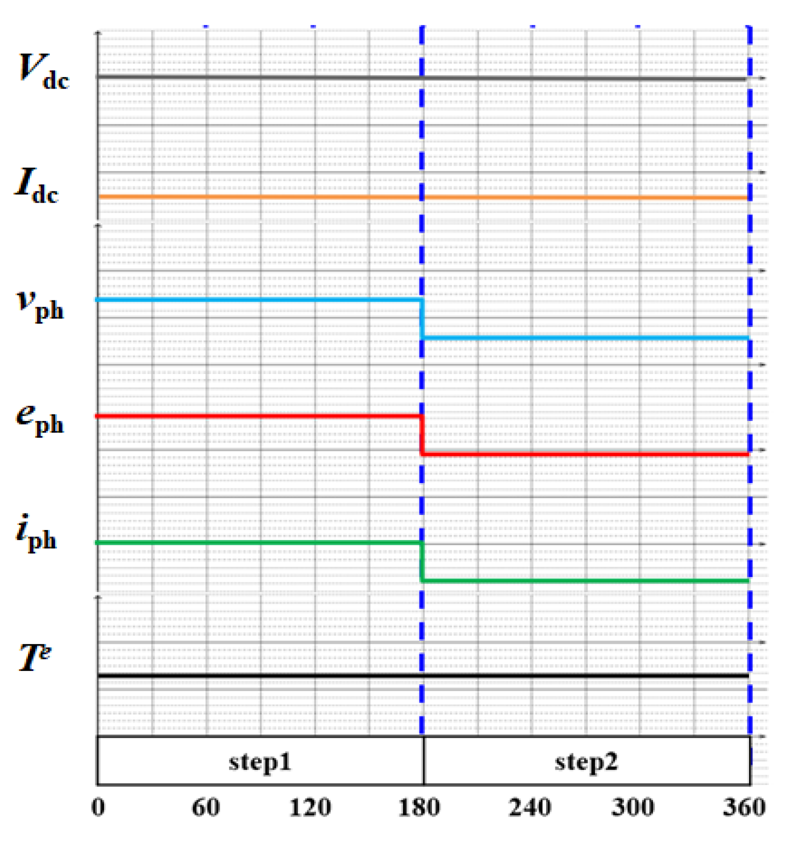
From the above equations, for constant power and torque, the back-EMF and phase current should take flat waveforms. In the case of a single-phase brushless direct current (BLDC) motor, the back-EMF alternates at an electrical angle of 180°, unlike in a direct current (DC) motor. Therefore, the single-phase BLDC motor can achieve constant output power and torque by exhibiting flat alternating waveforms of the back-EMF and phase current.
Figure 1 shows the relationship between the back-EMF, input voltage, input current, phase voltage, phase current, and torque in ideal conditions.
2.2. Actual Characteristics of a Single-Phase BLDC Motor
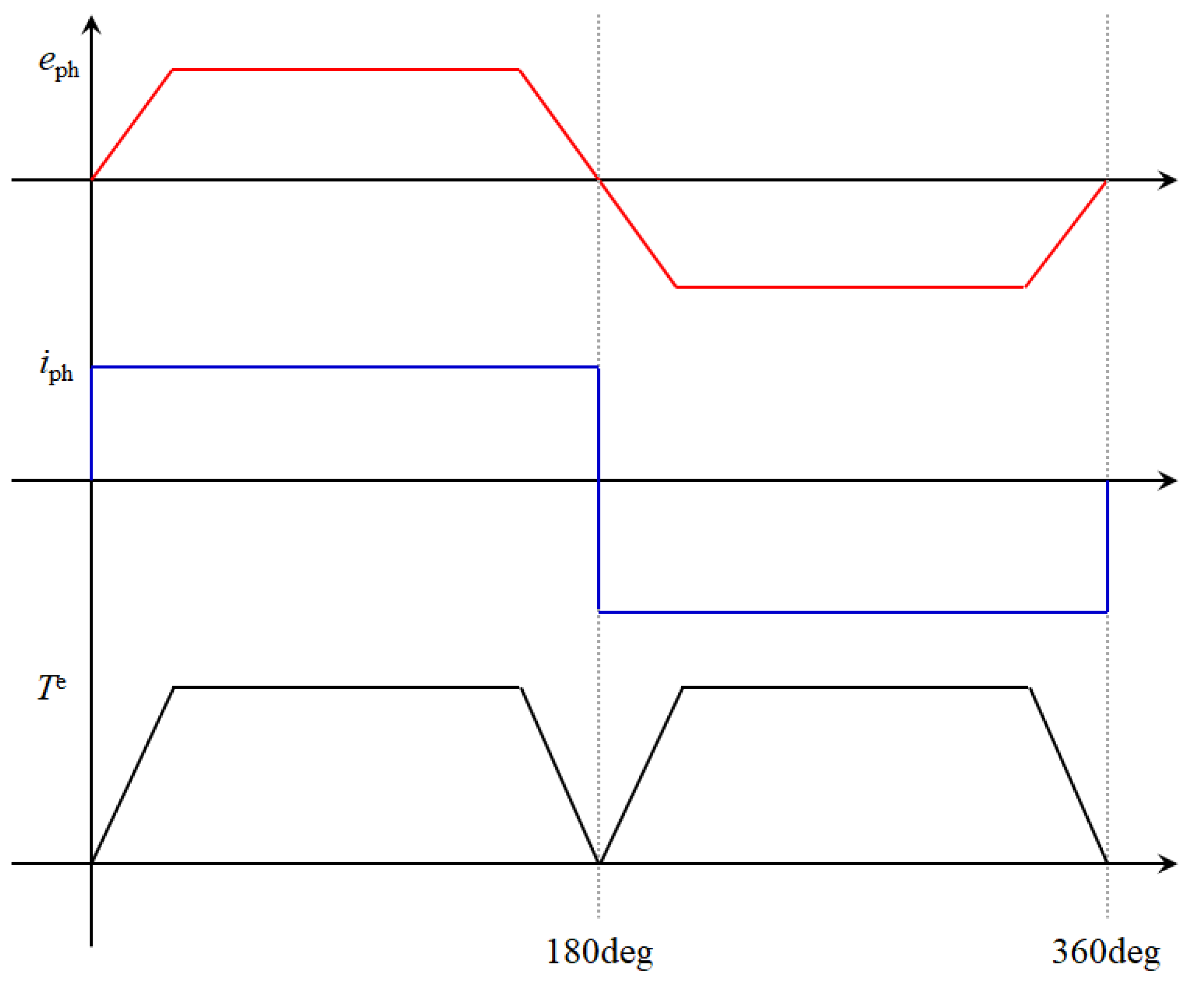
Although a single-phase BLDC motor can exhibit flat waveforms of the back-EMF in an ideal scenario, it can exhibit not only flat but also trapezoidal waveforms owing to its structural form. Thus, when back-EMF and input currents are multiplied, a dead point torque is generated at an electrical angle of 180° because zero crossing, which is the zero point of back-EMF, occurs inevitably.
The waveform of torque ripple is shown in Figure 2, when the trapezoidal waveform of the back-EMF and ideal waveform of the input current are applied to a single-phase BLDC motor.
As can be observed from Figure 2, the torque ripple is zero at 180° intervals; this causes vibrations and noise in single-phase BLDC motors.
2.3. Decomposition of Torque in a Single-Phase BLDC Motor
The torque components of single-phase claw-pole motors are mainly divided in two. These components are the alignment torque, which is generated owing to the interaction between the permanent magnet and input current, and the cogging torque, which is the difference in reluctance generated by the permanent magnet and electric steel of the stator [13].
The equation for these torque components is shown below.
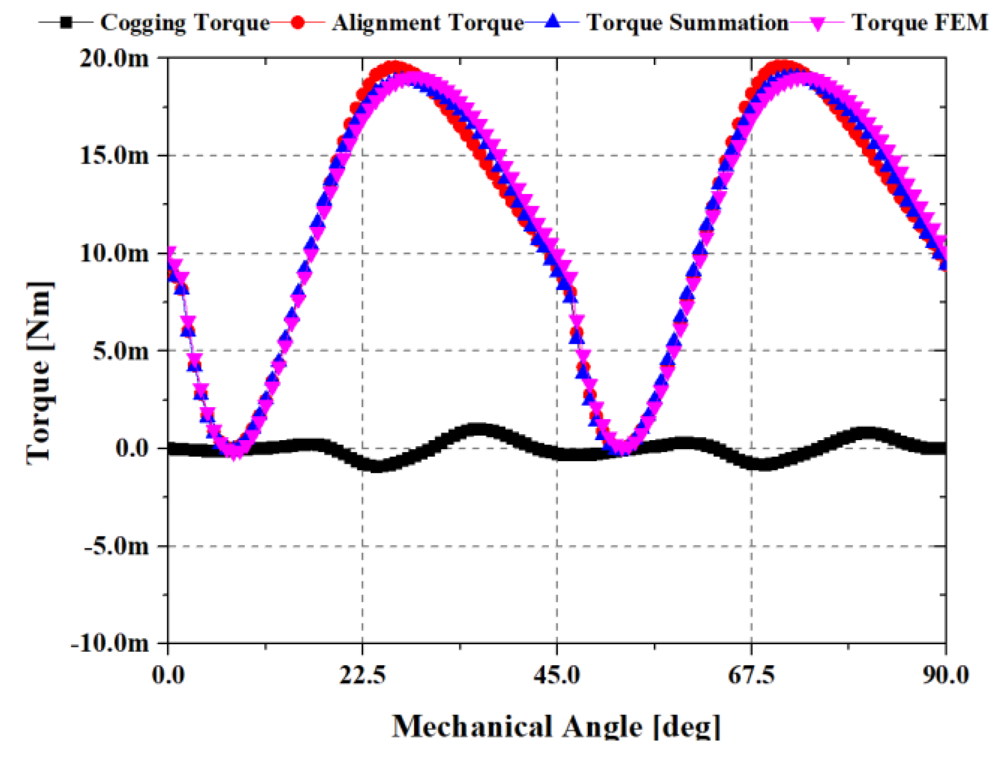
where T denotes the torque, Tal is the alignment torque of interaction between the permanent magnet and input current, and Tco is the cogging torque of the difference in reluctance. The relationship of the torque in Equation (5) is shown in Figure 3.
T = Tal + Tco
2.4. Current Source Analysis of a Single-Phase Claw-Pole Motor
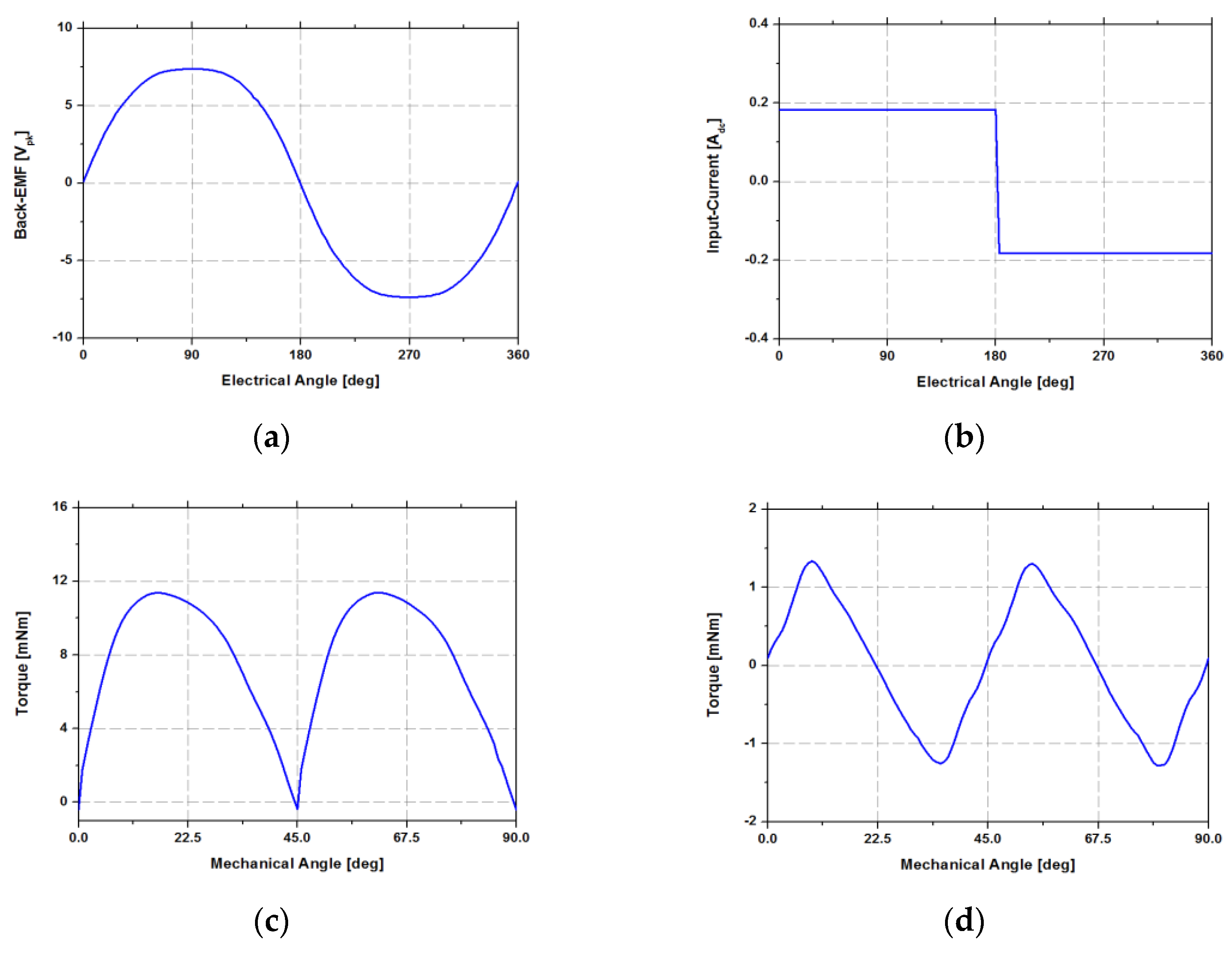
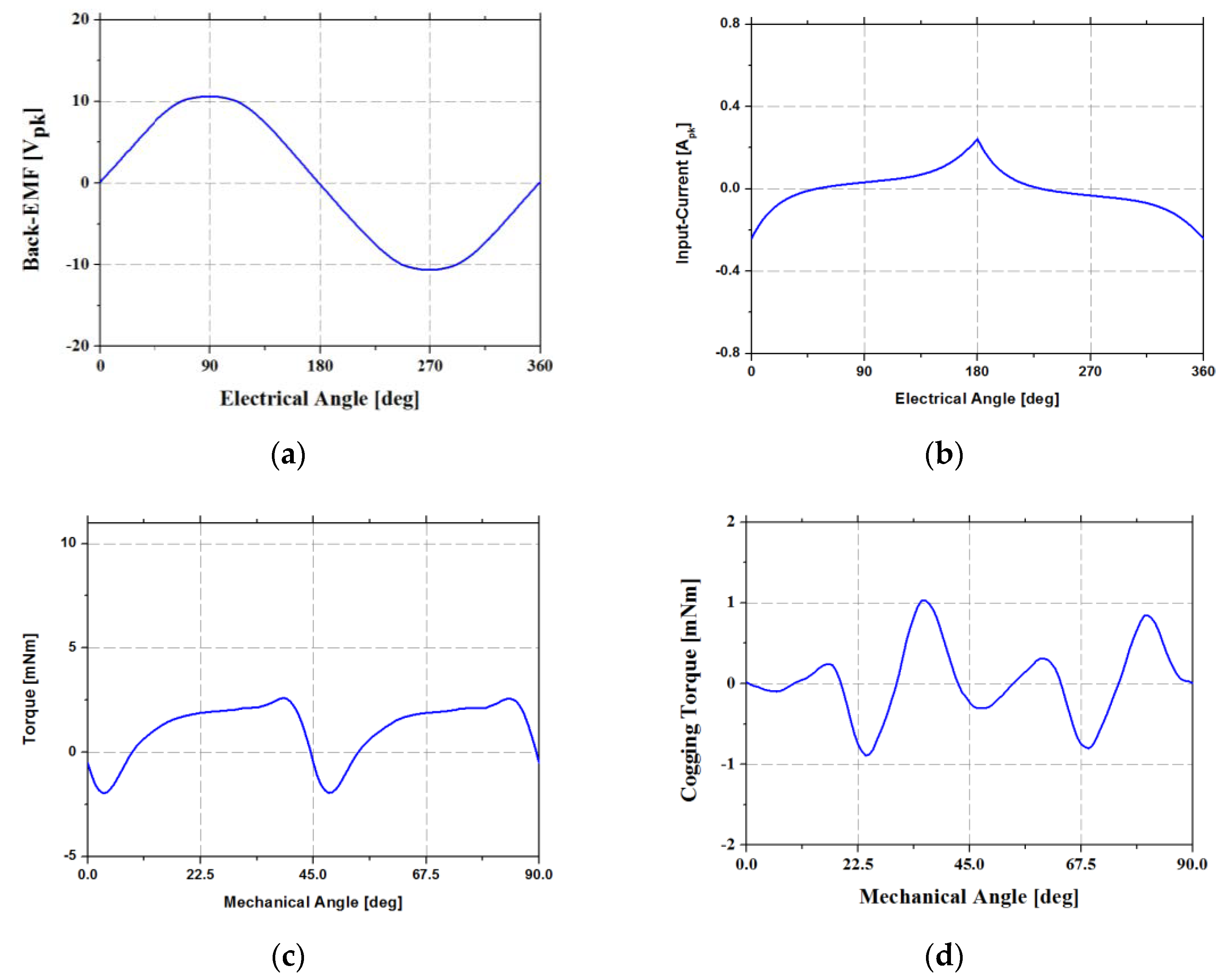
The waveforms of back-EMF, input current, torque, and cogging torque using finite element analysis are shown in Figure 4.
This result shows that the summation of the alignment and cogging torque is equal to torque. Further, the waveform of the output torque is the same as that shown in Figure 2.
T = ei/ωm +Tco
2.5. Voltage Source Analysis of a Single-Phase Claw-Pole Motor
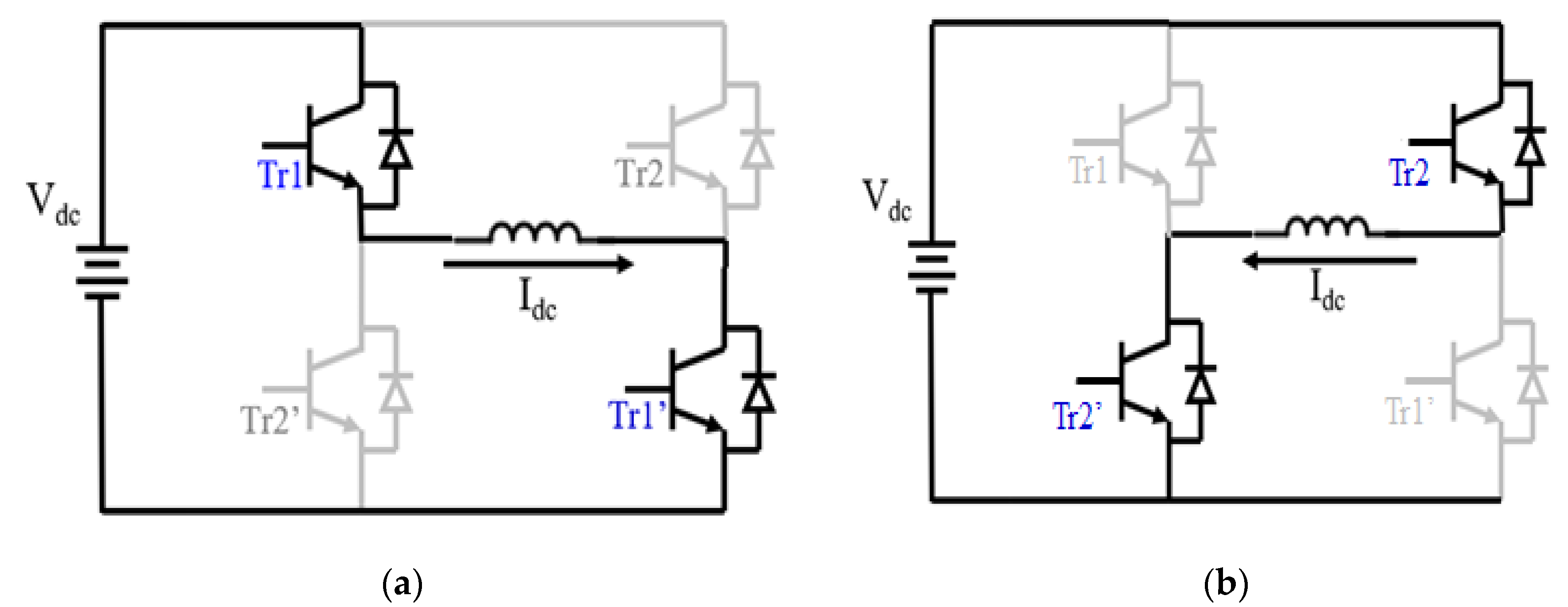
Four switching elements are required to conduct a two-step BLDC motor control of the single-phase BLDC machine. The control of the single-phase BLDC motor using four switching elements is carried out in two stages, as presented in Figure 5.
In Figure 5, a positive current is applied to a motor coil in the case of Figure 5a. However, a negative current is applied to the motor coil in the case of Figure 5b. Therefore, positive and negative currents can be applied to the motor coil, and the product of the current and back-EMF generates torque, according to Equation (4).
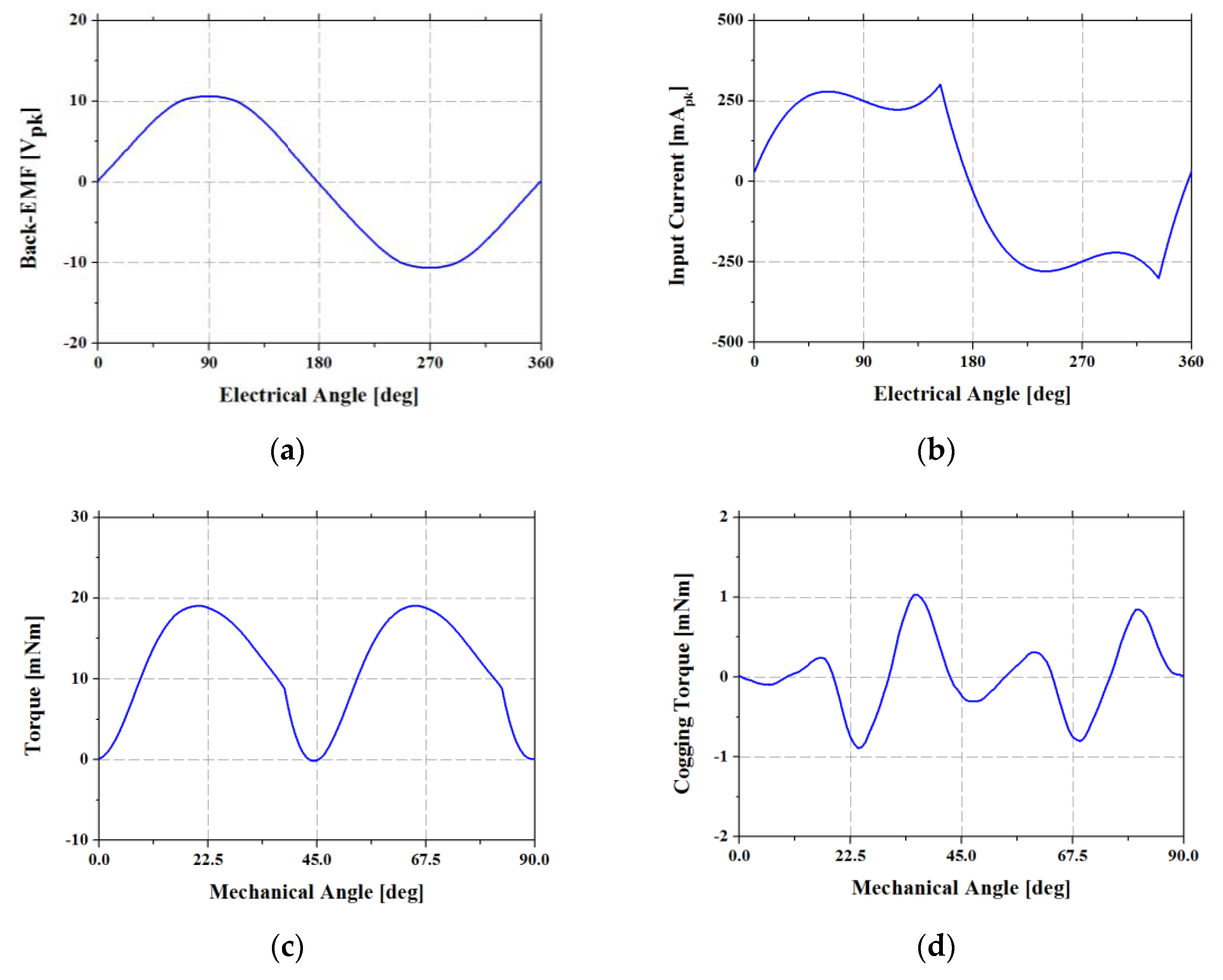
Figure 6 shows the result of voltage source analysis using finite element analysis (FEA) for the single-phase claw-pole motor with a two-step controller. In Figure 6, the waveforms consist of back-EMF, input current, output torque, and cogging torque.
Figure 6b shows the waveform of the input current using voltage source analysis. Unlike other motors, as the winding direction of the single-phase claw-pole motor is around its axis, a higher number of turns can be wound on a single-phase claw-pole motor, which is an inherent advantage. Thus, when the number of turns is significant, a current lagging phenomenon occurs owing to the high inductance of the coil. The torque generated by the product of the current and back-EMF takes negative values at regular intervals, as shown in Figure 6c. Consequently, the negative torque reduces the average torque value [8].
To overcome this phenomenon, it is necessary to apply the current phase advance method, in which the phase of the current is same with the back-EMF by changing the switching time of the controller [14].
The waveforms of back-EMF, input current, torque, and cogging torque, to which the phase advance method is applied to achieve a single-phase claw-pole motor, are shown in Figure 7. In the case of applying the phase advance method, as the torque does not take a negative value, the average torque increases in comparison to the case where the phase advance method is not applied.
3. Novel Method of Reducing Torque Ripple for a Single-Phase Claw-Pole Motor
In the previous section, the reason why the single-phase motor inevitably exhibits dead torque points was analyzed, and the method of improving dead torque points by applying the phase advance method was elucidated. However, as only applying the phase advance method has a limited effect on reducing torque ripple, a novel topology was applied to a single-phase claw-pole motor to further reduce its torque ripple.
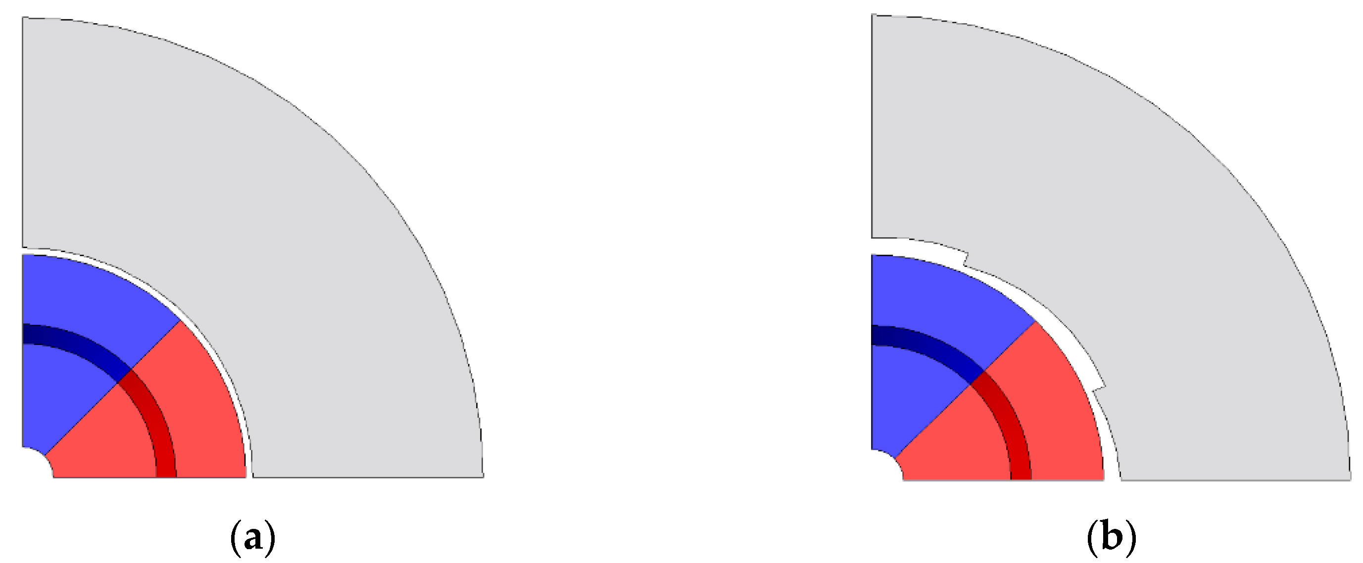
The novel method was applied to make the air gap asymmetrical by tilting the claw so that cogging torque occurred asymmetrically. In this method, the aim is to make the asymmetric cogging torque have a positive value for every 180° electrical angle. Since the alignment torque caused by the permanent magnet and current becomes zero torque at an electrical angle of 180°, the positive cogging torque can increase the torque, which is generated by the summation of the alignment and cogging torques, such that it attains a positive value at that angle. A comparison between the stator claw topologies with and without applying the novel design is shown in Figure 8.
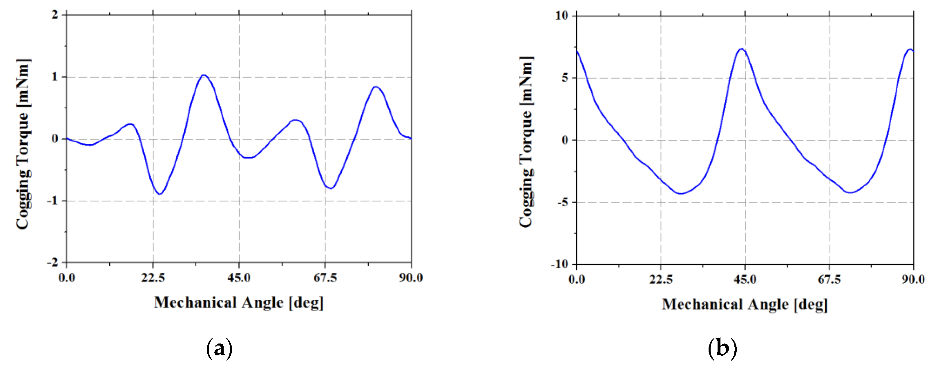
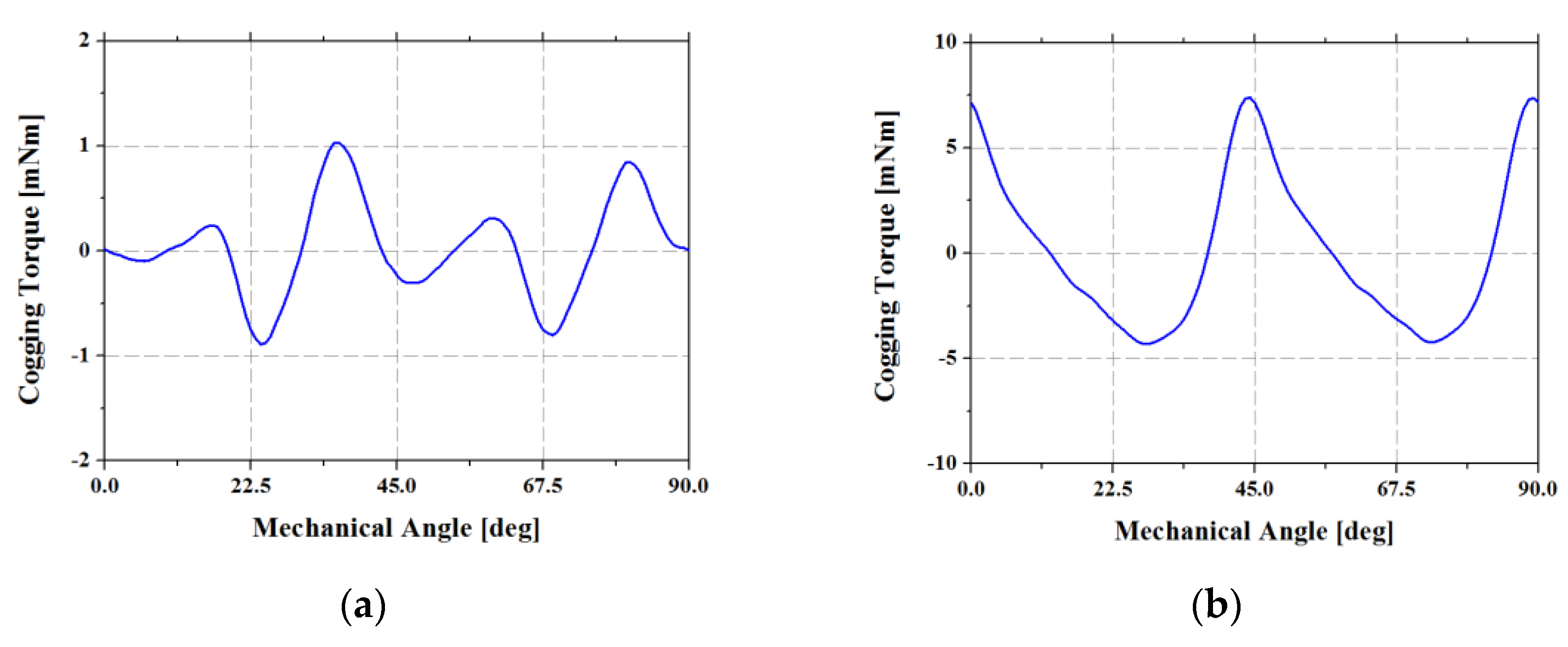
The waveforms of the cogging torque obtained via FEA for each model are shown in Figure 9. In Figure 9a, it can be seen that the base model and symmetric claw model exhibited zero torque at a mechanical angle of 45°, which is equal to an electrical angle of 180° in an eight-pole machine. Therefore, the summation of the alignment and cogging torques was equal to zero at a mechanical angle of 45°. In contrast, the novel asymmetric claw model did not exhibit zero torque at a mechanical angle of 45°, as shown in Figure 9b. Thus, the summation of the alignment and cogging torques was not equal to zero at a mechanical angle of 45°. The torque ripple was reduced by this method [15].
4. Modeling and Analysis of the Asymmetric Model
4.1. Optimal Size of the Asymmetric Air Gap
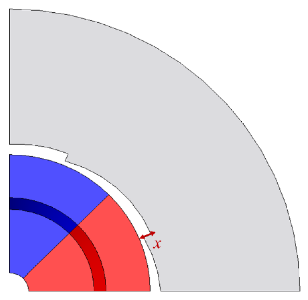
In order to find the optimal size of the asymmetric air gap, a case study with the design variable was carried out. The design variable is shown in Figure 10.
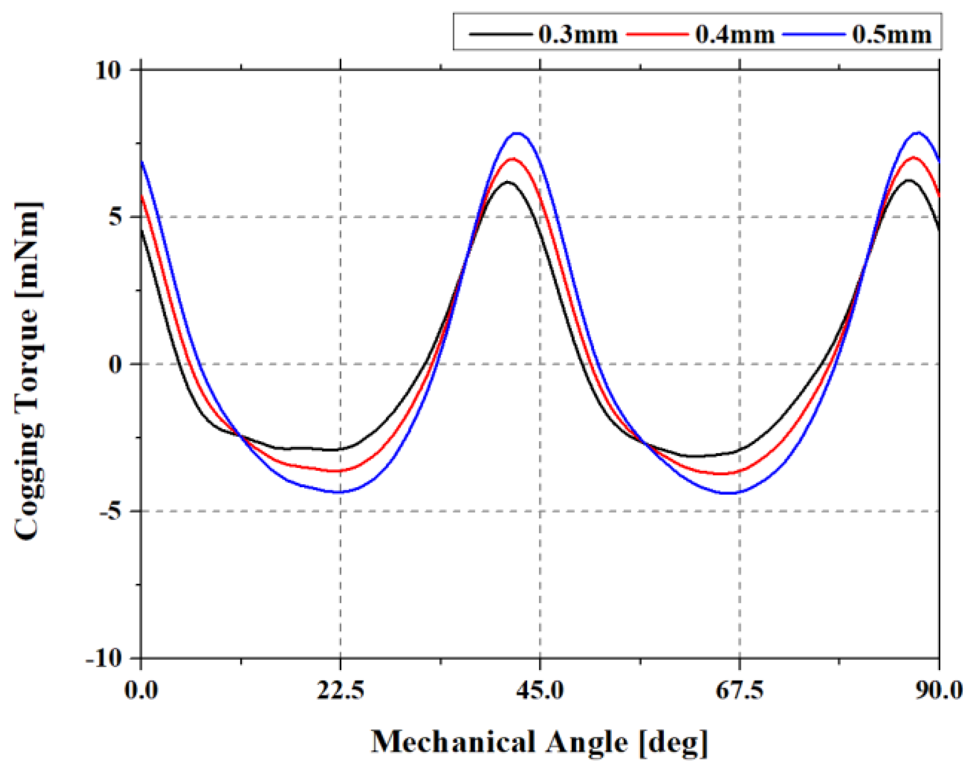
The design variable, x, was chosen 0.3 mm from where the manufacturing tolerance was secured to 0.5 mm, where the fill factor was able to be maintained. In order to minimize torque ripple of the motor, the target parameter was set as the maximum cogging torque that boosts the minimum torque value. Except for the variable, all other conditions were the same. The maximum value and waveform of the cogging torque for each value of the variable are shown in Table 1 and Figure 11, respectively.
According to the results of Table 2, the size of the asymmetric air gap was selected as 0.5 mm. The modeling of the proposed model was carried out with a 0.5 mm asymmetric air gap, and the simulation result of it was compared with the base model.
4.2. Specifications and Three-Dimensional Modeling
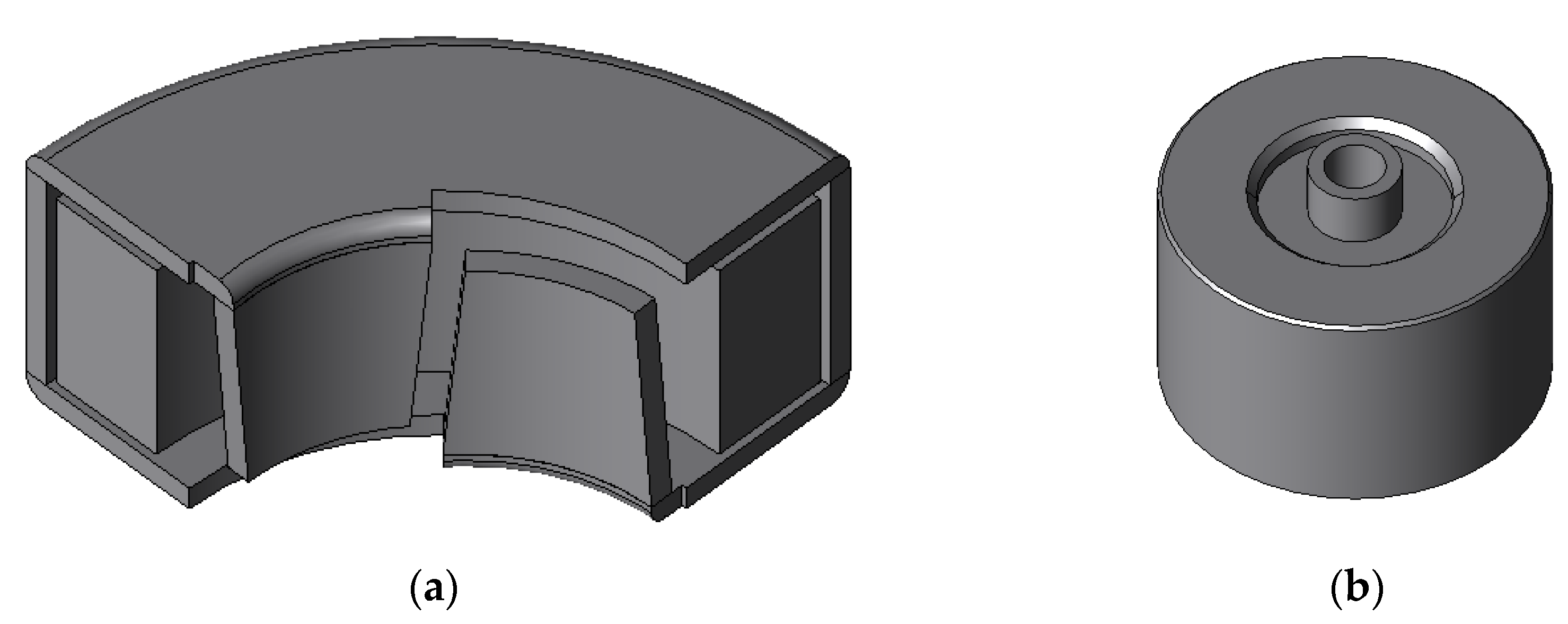
The modeling and analysis of the base and novel models with FEA were carried out. To consider structural characteristics, three-dimensional (3D) modeling and analysis with FEA were executed. Transient analysis was performed to reflect the voltage source analysis. The design specifications and topologies are shown in Table 2 and Figure 12, respectively [16].
4.3. Analysis Results Using the Finite Element Method
In accordance with the specifications in Table 2, the modeling for the proposed model shown in Figure 12 was performed, and characteristic analysis using 3D FEA was conducted. Additionally, the result of this analysis was compared with that of the base model.
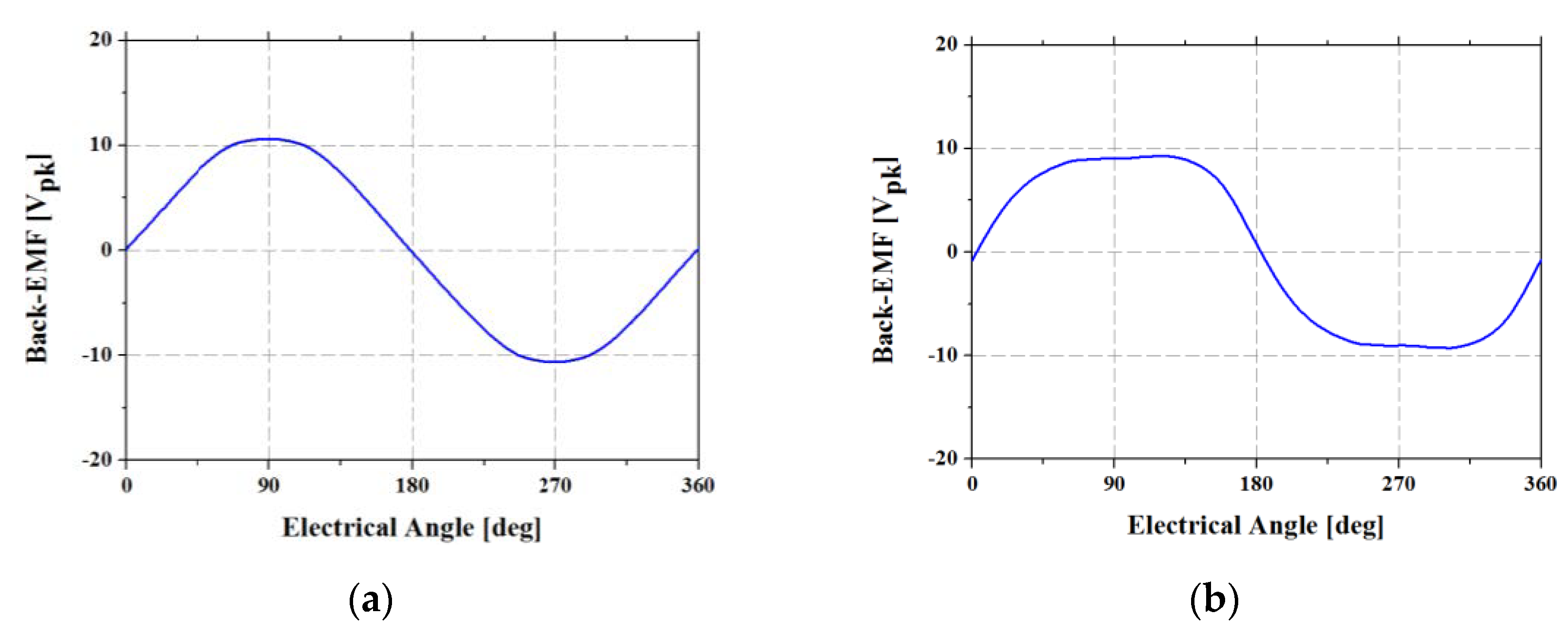
First, a no-load analysis was carried out to examine the back-EMF and cogging torque. The waveforms obtained via the no-load analysis are shown in Figure 13 and Figure 14.
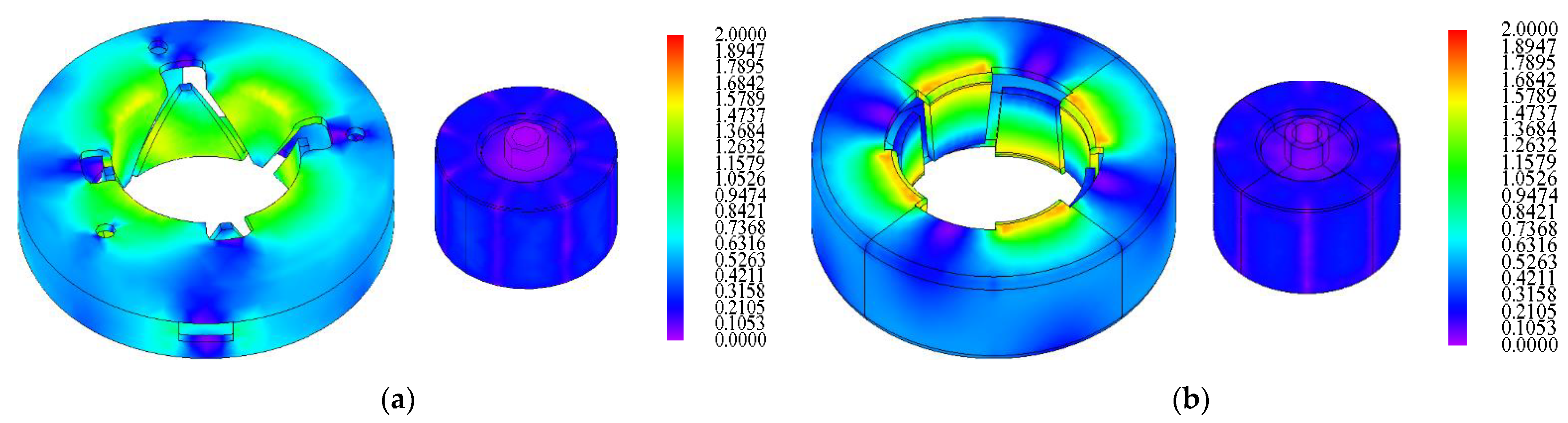
The root mean square (RMS) and peak values of the back-EMF in the base model were 7.49 and 10.63 V, respectively. In the proposed model, the RMS value of the back-EMF was 7.47 V, and its peak value was 9.28 V. The peak-to-peak value of the cogging torque was 1.9 mNm in the base model and 11.7 mNm in the proposed model. From this result, it can be observed that although the proposed model exhibited a higher peak-to-peak value of the cogging torque compared to that of the base model, this did not pose a problem because of the improved characteristics of the torque and torque ripple in this case. Figure 15 shows the magnetic flux density in the no-load condition.
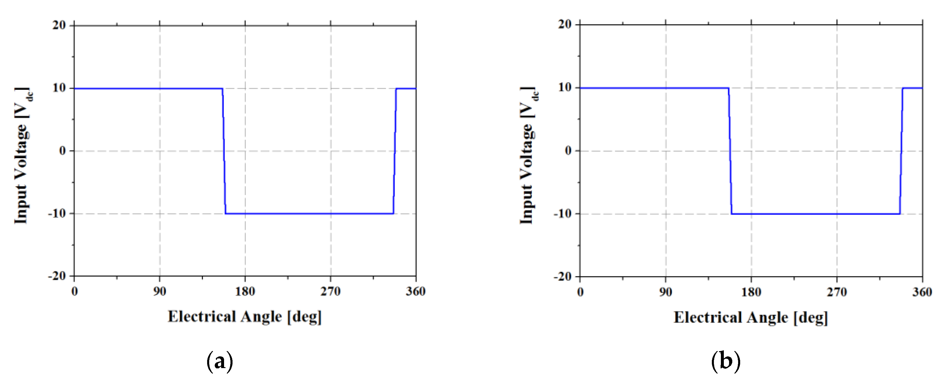
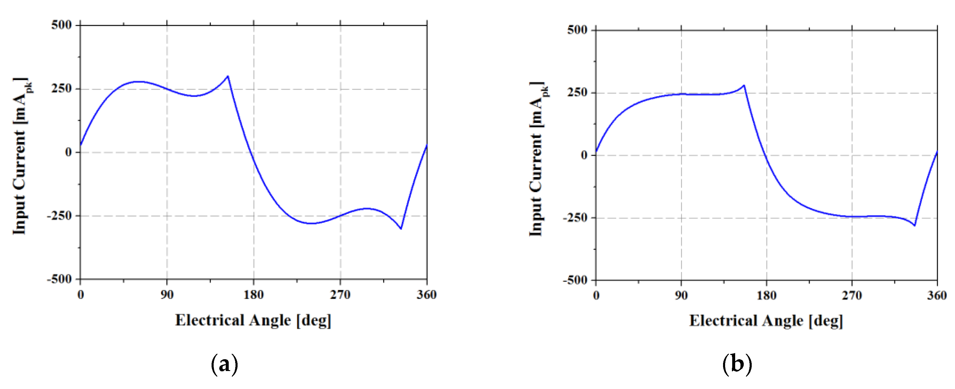
Subsequently, the characteristics were analyzed in the load condition. The characteristics of the input current, input voltage, and torque ripple using the phase advance method were evaluated in both models. The waveforms of the input voltage, input current, and torque ripple are shown in Figure 16, Figure 17 and Figure 18, respectively. DC 10 V was used as the input voltage, and the phase advance method was also used to minimize the torque ripple in both models. The lead angle for the phase advance was electrical angle 22.5°. From the result of the load analysis, the RMS values of the input currents in two models were 211 mA and 281 mA, respectively.
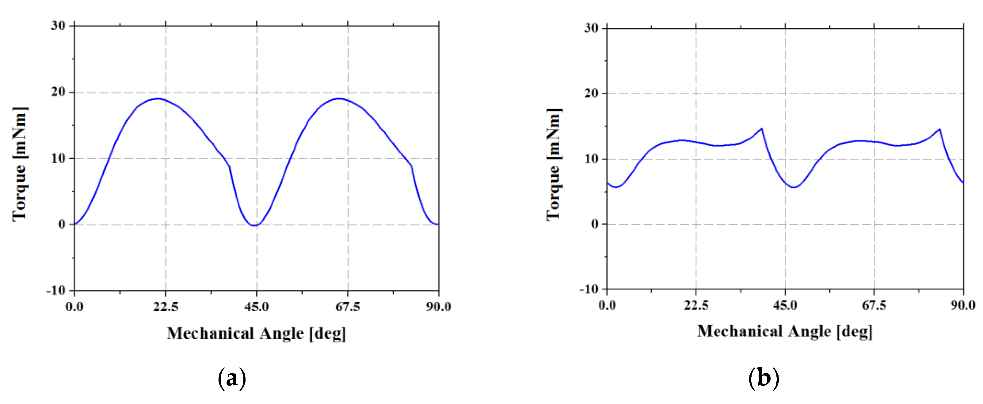
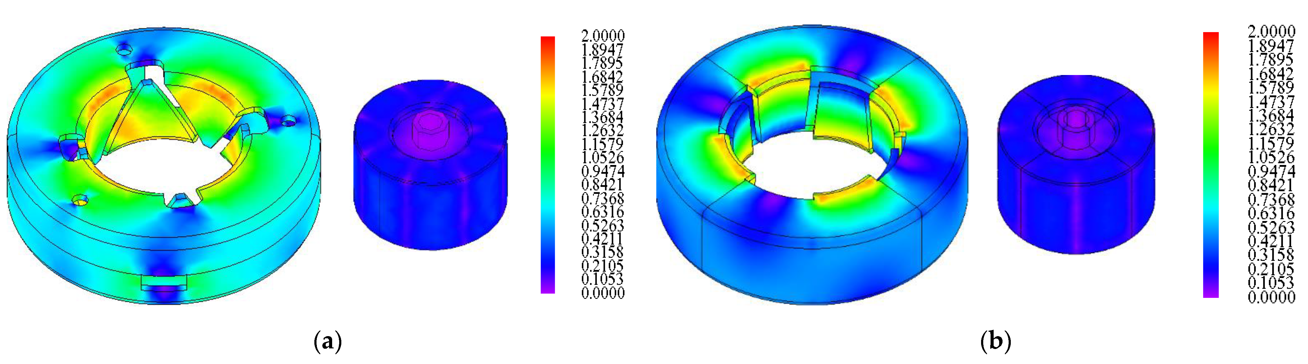
The average torque of the base model was 11.4 mNm, and that of the proposed model was 11.0 mNm. The peak-to-peak value of the torque on the base model was 19.2 mNm and on the proposed model was 9.0 mNm. From the results, it can be seen that these models satisfied the target design specifications. In the case of torque ripple, the base model exhibited a value of 168.4%, which did not satisfy the target design specification. However, the proposed model exhibited a torque ripple of 81.9%, which satisfied the target design specification. Figure 19 shows the magnetic flux density of the two models in the load condition.
As a result of the novel design, the torque ripple was reduced by 86.5% in the proposed model compared to that in the base model.
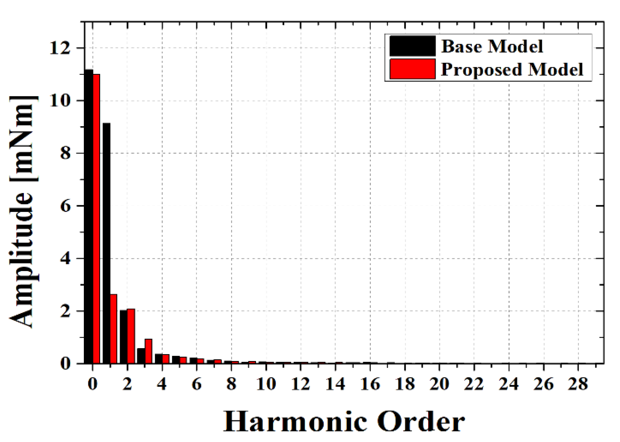
In addition, the torque waveform of each model was compared based on the frequency domain using fast Fourier transform (FFT). The comparison of torque waveform using FFT is shown Figure 20.
As the result of FFT analysis of the torque waveform, the first harmonic of the proposed model was significantly reduced compared to the base model. The second and third harmonics of the proposed model were higher than the base model, but the difference was not significant. Considering that the first harmonic of the base model was considerably higher than that of the proposed model, it was confirmed that the base model took higher fluctuation of the torque than the proposed model. Therefore, the base model was more vulnerable to noise and vibration than the proposed model.
5. Experimental Test Result
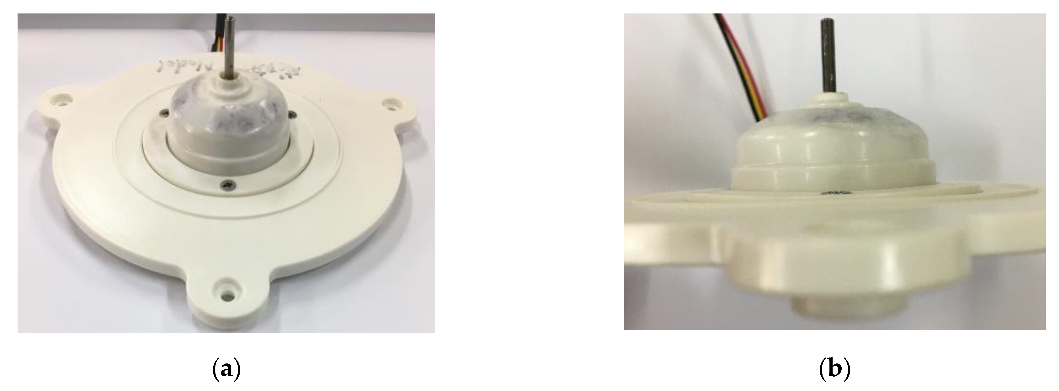
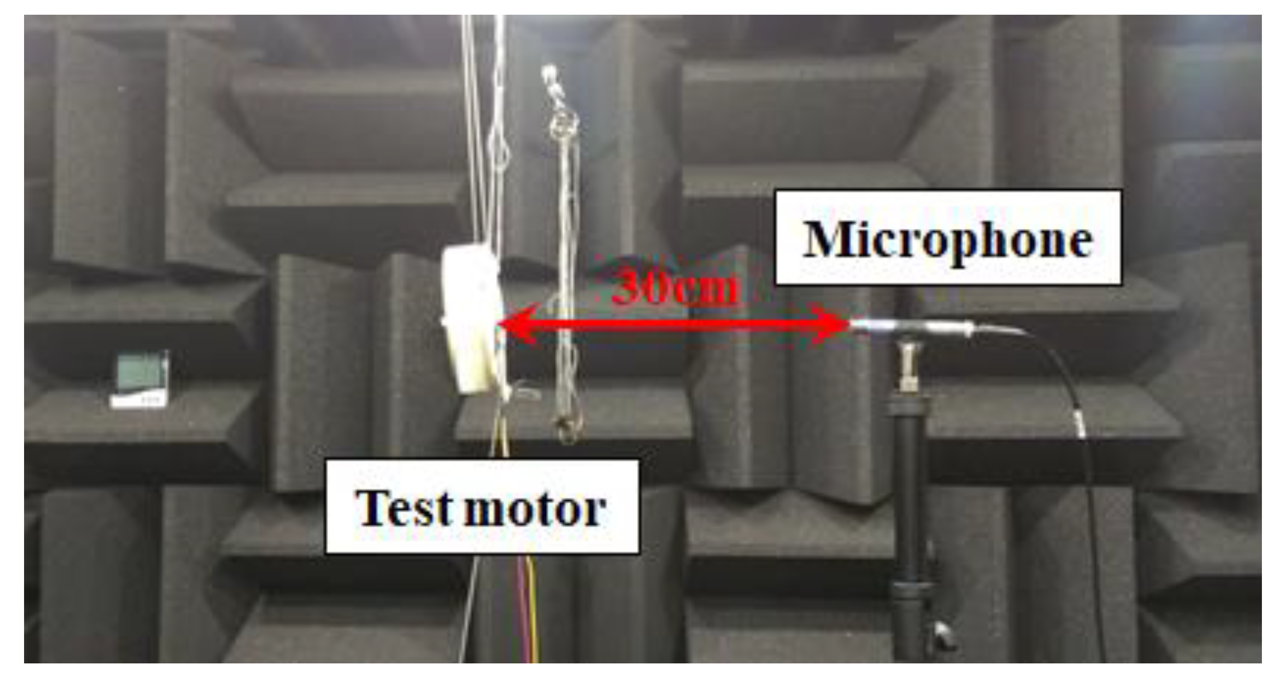
The purpose of reducing the torque ripple is the minimization of the noise of the claw-pole motor. Therefore, the base and proposed models were manufactured, and the noise was evaluated using a microphone in an anechoic room. The manufactured proposed model and experimental environments are shown in Figure 21 and Figure 22, respectively [17].
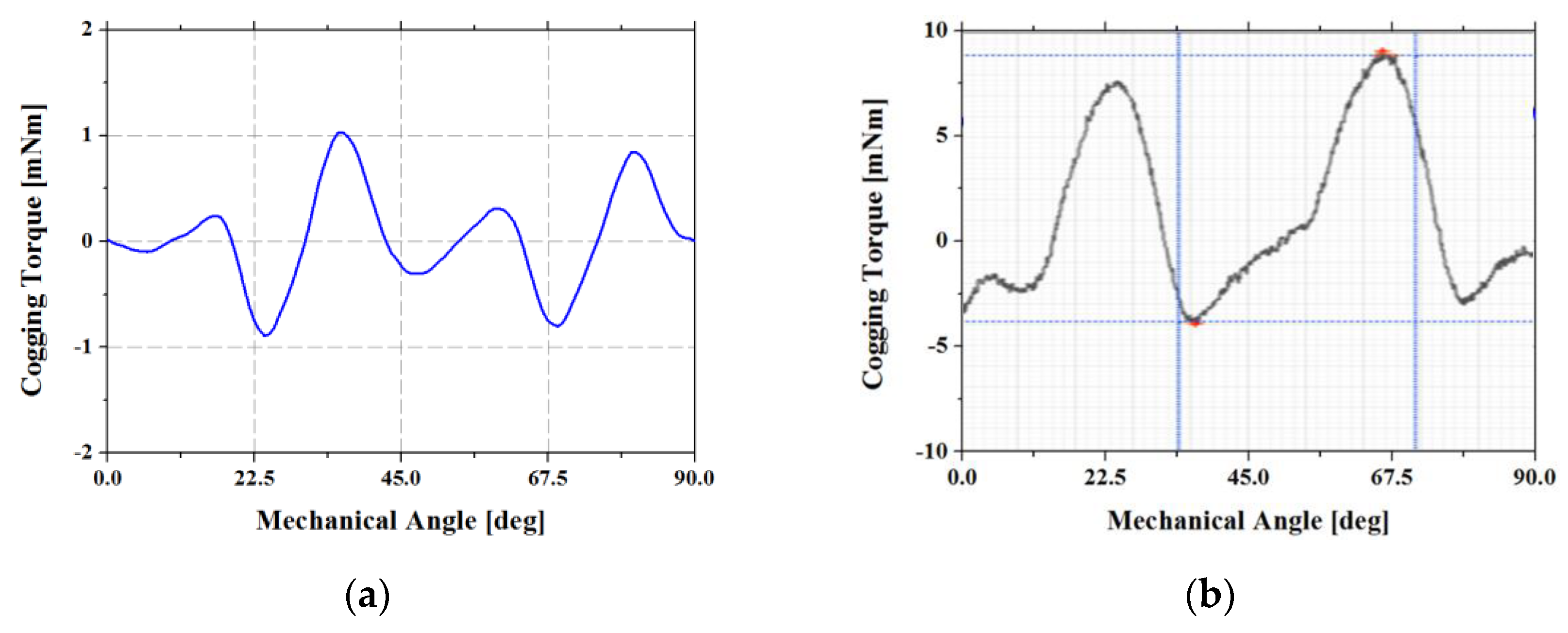
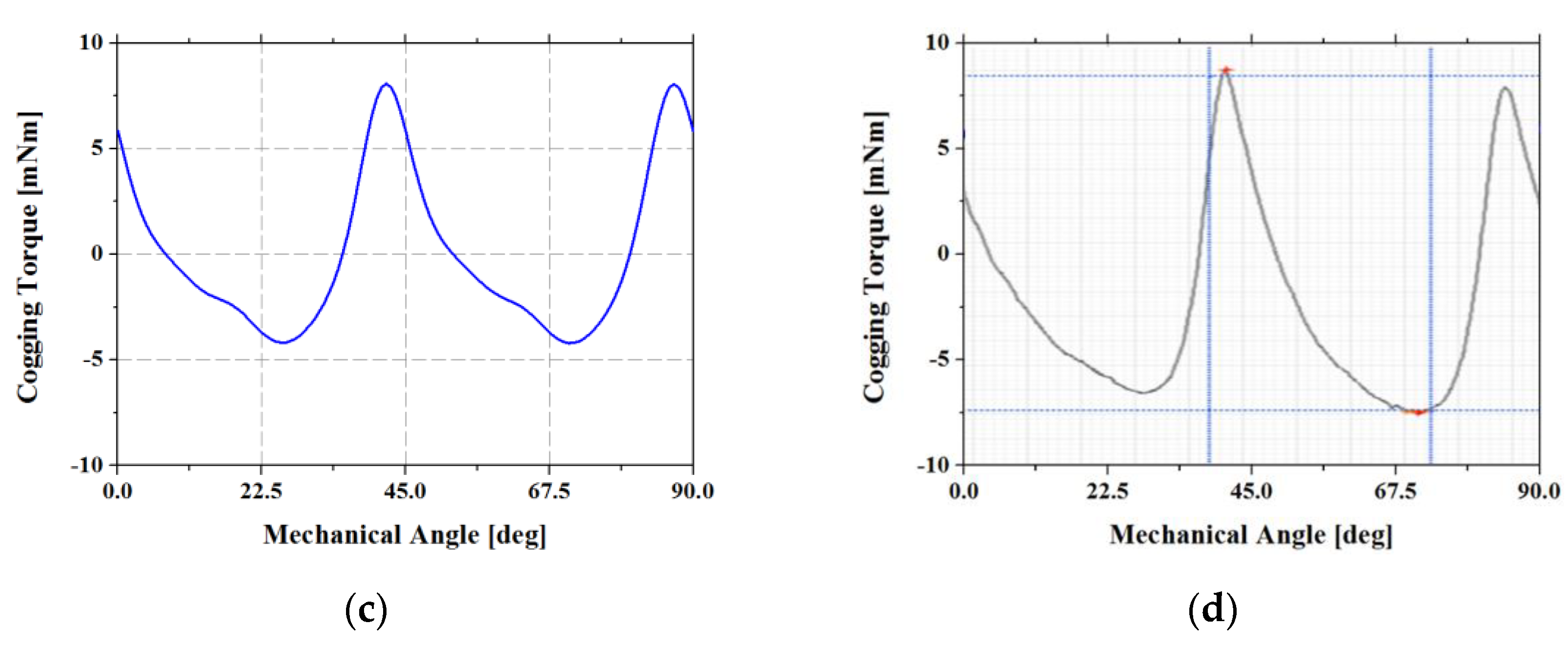
To validate the motor manufactured based on the proposed design, the FEA analysis result of the cogging torque and the corresponding experimental result were compared. The result of this comparison is shown in Figure 23.
By comparing the shapes of the waveforms, it was confirmed that the proposed model was well manufactured. The analysis result for the value of the peak-to-peak cogging torque was 12.3 mNm, and its measured result was 14 mNm. Next, the noises generated by the base and proposed models were measured, and the results were compared. The experimental criteria were as follows:
- The measurement was performed with a microphone in a completely enclosed anechoic chamber.
- The measurement distance was 30 cm from the motor.
- The measurement was carried out by attaching the fan to the motor.
- The measurement was performed from the front, rear, and side of the motor.
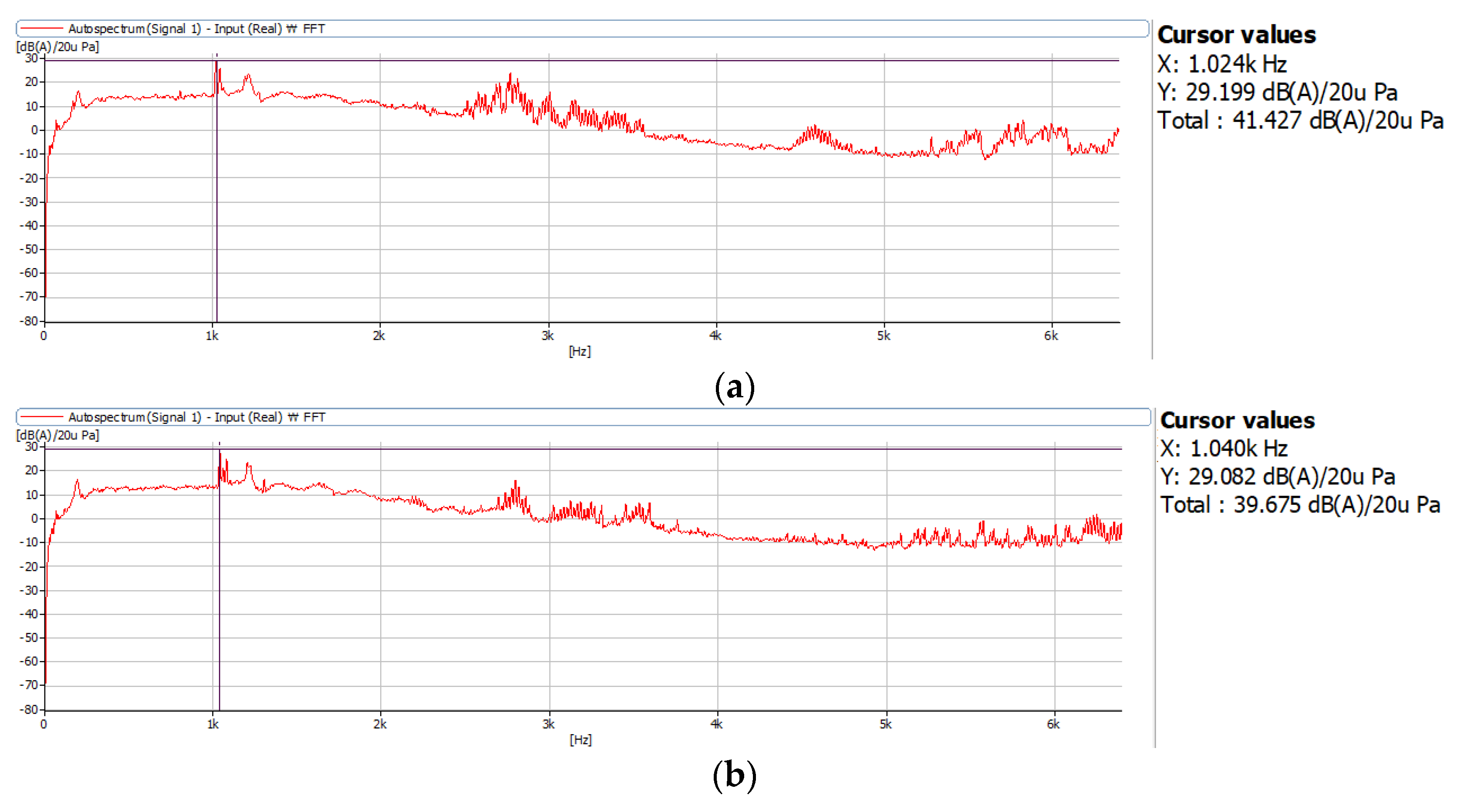
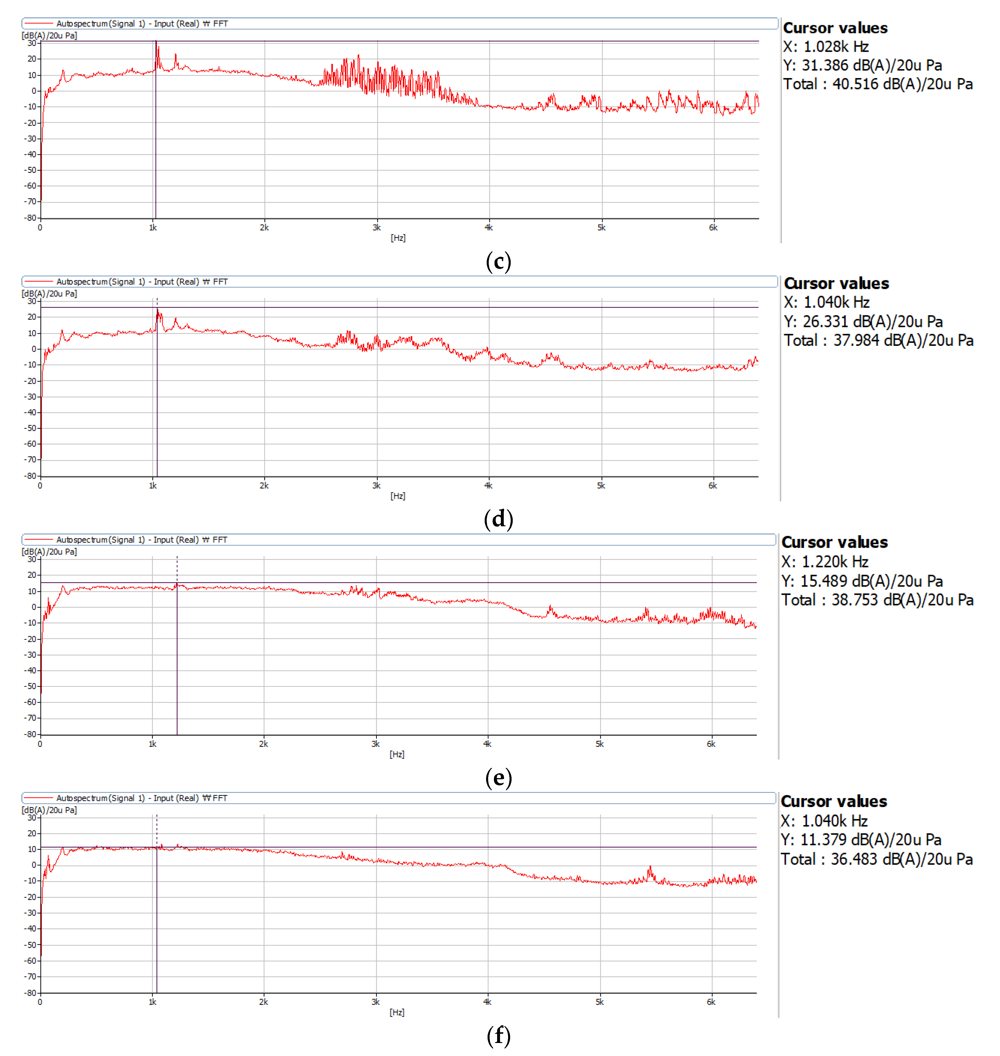
The noise measured from the front of the motor was 41.427 dB for the base model, whereas that of the proposed model was 39.675 dB, which was an approximately 1.75 dB decrease in noise. In the case of the noise measured from the rear, the base model generated 40.516 dB, and the proposed model generated 37.984 dB. Thus, the proposed model decreased the noise by approximately 2.53 dB. Finally, on the side of the motor, the noise of the base model was measured as 38.753 dB, and that of the proposed model was 36.483 dB. In this case, the proposed model decreased the noise by approximately 2.27 dB. Thus, the noise generated by the proposed model was lower than that generated by the base model in all cases of the experiment. The results of this experiment are shown in Figure 24.
6. Conclusions
In this study, a novel design for reducing the noise generated by single-phase claw-pole motors was proposed. The torque of single-phase claw-pole motors comprises magnetic alignment and cogging torques, of which the magnetic alignment torque inevitably becomes zero at an electrical angle of 180°; to address this issue, a novel method for substantially increasing the magnetic alignment torque at an electrical angle of 180° was proposed. The proposed method is to tilt a stator claw to make the cogging torque positive at an electrical angle of 180°.
Three-dimensional modeling and FEA were conducted to analyze the base and proposed models. The torque ripple of the proposed model was reduced by 86.5% compared to the base model. In addition, FFT analysis of torque waveform was conducted. As a result of the FFT analysis, the first harmonic of the base model as considerably higher than the proposed model, and it was confirmed that the base model was vulnerable to noise and vibration compared to the proposed model.
These models were manufactured to conduct noise measurement experiments. Consequently, it was confirmed that the noise generated by the proposed model was lower than that generated by the base model in the front, rear, and side. Thus, the effectiveness of the proposed method was confirmed.
As a future plan, we will study the 2D equivalent modeling of a single-phase claw-pole motor with asymmetric air gap. This is for fast analysis and optimization by using a quasi-2D equivalent circuit for a single-phase claw-pole motor that requires 3D analysis due to its structural characteristics.
Author Contributions
Conceptualization, J.-H.L. and S.-Y.J.; methodology, J.-H.L.; software, J.-H.L.; validation, J.-H.L. and S.-Y.J.; formal analysis, J.-H.L.; investigation, J.-H.L.; resources, J.-H.L.; data curation, J.-H.L.; writing—original draft preparation, J.-H.L.; writing—review and editing, J.-H.L. and S.-Y.J.; visualization, J.-H.L.; supervision, S.-Y.J.; project administration, S.-Y.J.; funding acquisition, S.-Y.J. All authors have read and agreed to the published version of the manuscript.
Funding
This research received no external funding.
Institutional Review Board Statement
Not applicable.
Informed Consent Statement
Not applicable.
Data Availability Statement
Not applicable.
Conflicts of Interest
The authors declare no conflict of interest.
References
- Dianov, A. Stoppage noise reduction of reciprocating compressors. IEEE Trans. Ind. Appl. 2021, 57, 4376–4384. [Google Scholar] [CrossRef]
- Niki, T. Power Electronics and Control Technologies for Household Washer. In Proceedings of the 2018 International Power Electronics Conference (IPEC-Niigata 2018-ECCE Asia), Niigata, Japan, 20–24 May 2018; pp. 856–859. [Google Scholar]
- Xu, M.; Liu, G.; Zhao, W. Torque Ripple Improvement for Ferrite-Assisted Synchronous Reluctance Motor by Using Asymmetric Flux-barrier Arrangement. In Proceedings of the 2018 IEEE International Magnetics Conference (INTERMAG), Singapore, 23–27 April 2018; p. 1. [Google Scholar]
- Babetto, C.; Bacco, G.; Bianchi, N. Synchronous reluctance machine optimization for high-speed applications. IEEE Trans. Energy Convers. 2018, 33, 1266–1273. [Google Scholar] [CrossRef]
- Lee, W.; Kim, J.H.; Choi, W.; Sarlioglu, B. Torque ripple minimization control technique of high-speed single-phase brushless DC motor for electric turbocharger. IEEE Trans. Veh. Technol. 2018, 67, 10357–10365. [Google Scholar] [CrossRef]
- Leitner, S.; Gruebler, H.; Muetze, A. Innovative low-cost sub-fractional hp BLDC claw-pole machine design for fan applications. IEEE Trans. Ind. Appl. 2019, 55, 2558–2568. [Google Scholar] [CrossRef]
- Leitner, S.; Gruebler, H.; Muetze, A. Cogging torque minimization and performance of the sub-fractional HP BLDC claw-pole motor. IEEE Trans. Ind. Appl. 2019, 55, 4653–4664. [Google Scholar] [CrossRef]
- Gruebler, H.; Leitner, S.; Muetze, A.; Schoener, G. Improved switching strategy for a single-phase brushless direct current fan drive and its impact on efficiency. IEEE Trans. Ind. Appl. 2018, 54, 6050–6059. [Google Scholar] [CrossRef]
- Park, S.; Kim, W.; Kim, S.I. A numerical prediction model for vibration and noise of axial flux motors. IEEE Trans. Ind. Electron. 2014, 61, 5757–5762. [Google Scholar] [CrossRef]
- Binojkumar, A.C.; Saritha, B.; Narayanan, G. Acoustic noise characterization of space-vector modulated induction motor drives—An experimental approach. IEEE Trans. Ind. Electron. 2015, 62, 3362–3371. [Google Scholar] [CrossRef]
- Fang, Y.; Zhang, T. Vibroacoustic characterization of a permanent magnet synchronous motor powertrain for electric vehicles. IEEE Trans. Energy Convers. 2018, 33, 272–280. [Google Scholar] [CrossRef]
- Zhu, H.; Xiao, X.; Li, Y. Torque ripple reduction of the torque predictive control scheme for permanent-magnet synchronous motors. IEEE Trans. Ind. Electron. 2012, 59, 871–877. [Google Scholar] [CrossRef]
- Wanjiku, J.; Khan, M.A.; Barendse, P.S.; Pillay, P. Influence of slot openings and tooth profile on cogging torque in axial-flux PM machines. IEEE Trans. Ind. Electron. 2015, 62, 7578–7589. [Google Scholar] [CrossRef]
- Cha, W.J.; Cho, Y.W.; Kwon, J.M.; Kwon, B.H. Highly efficient microinverter with soft-switching step-up converter and single-switch-modulation inverter. IEEE Trans. Ind. Electron. 2015, 62, 3516–3523. [Google Scholar]
- Choo, Y.; Hwang, H.; Cho, J.; Kim, C.; Kim, J.; Hwang, S.H.; Choi, J.Y.; Lee, C. Investigation of Systematic Efficiency in a High-Speed Single-Phase Brushless DC Motor Using Multi-Physics Analysis for a Vacuum Cleaner. IEEE Trans. Magn. 2019, 55, 1–6. [Google Scholar] [CrossRef]
- Kim, J.S.; Lee, J.H.; Kim, D.W.; Kim, Y.J.; Jung, S.Y. Design strategy for single phase claw-pole type motor considering design parameter. In Proceedings of the 2016 19th International Conference on Electrical Machines and Systems (ICEMS), Chiba, Japan, 13–16 November 2016; pp. 1–4. [Google Scholar]
- Hernando, M.M.; Fernández, A.; Arias, M.; Rodriguez, M.; Alvarez, Y.; Las-Heras, F. EMI radiated noise measurement system using the source reconstruction technique. IEEE Trans. Ind. Electron. 2008, 55, 3258–3265. [Google Scholar] [CrossRef]
Figure 1.
Relationship between parameters of a single-phase BLDC motor in ideal conditions.

Figure 2.
Relationship among the trapezoidal back-EMF, ideal direct current, and torque ripple.

Figure 3.
Relation among alignment, cogging, and output torque.

Figure 4.
Current source analysis of a single-phase claw-pole motor using finite element analysis: (a) waveform of back-EMF; (b) waveform of input current; (c) waveform of torque; (d) waveform of cogging torque.
Figure 4.
Current source analysis of a single-phase claw-pole motor using finite element analysis: (a) waveform of back-EMF; (b) waveform of input current; (c) waveform of torque; (d) waveform of cogging torque.

Figure 5.
Current flow direction due to switch conduction: (a) Step 1: Tr1 and Tr’ conduction; (b) Step 2: Tr2 and Tr2’ conduction.
Figure 5.
Current flow direction due to switch conduction: (a) Step 1: Tr1 and Tr’ conduction; (b) Step 2: Tr2 and Tr2’ conduction.

Figure 6.
Voltage source analysis of the result of a single-phase claw-pole motor using finite element analysis: (a) waveform of back-EMF; (b) waveform of input current; (c) waveform of torque; (d) waveform of cogging torque.
Figure 6.
Voltage source analysis of the result of a single-phase claw-pole motor using finite element analysis: (a) waveform of back-EMF; (b) waveform of input current; (c) waveform of torque; (d) waveform of cogging torque.

Figure 7.
Voltage source analysis of the result of a single-phase claw-pole motor using finite element analysis with the phase advance method: (a) waveform of back-EMF; (b) waveform of input current; (c) waveform of torque; (d) waveform of cogging torque.
Figure 7.
Voltage source analysis of the result of a single-phase claw-pole motor using finite element analysis with the phase advance method: (a) waveform of back-EMF; (b) waveform of input current; (c) waveform of torque; (d) waveform of cogging torque.

Figure 8.
Topology comparison between the base and proposed model: (a) base model; (b) proposed model.
Figure 8.
Topology comparison between the base and proposed model: (a) base model; (b) proposed model.

Figure 9.
Comparison of cogging torque between the base and proposed model: (a) base model; (b) proposed model.
Figure 9.
Comparison of cogging torque between the base and proposed model: (a) base model; (b) proposed model.

Figure 10.
Selection of the design variable.

Figure 11.
Waveform of the cogging torque for each design variable.

Figure 12.
Stator and rotor topologies of the proposed model: (a) stator; (b) rotor.

Figure 13.
Comparison of back-EMF waveforms: (a) base model; (b) proposed model.

Figure 14.
Comparison of cogging torque waveforms: (a) base model; (b) proposed model.

Figure 15.
Magnetic flux densities of the base and proposed models in the no-load condition (left side, stator, rotor, and legend are shown): (a) base model; (b) proposed model.
Figure 15.
Magnetic flux densities of the base and proposed models in the no-load condition (left side, stator, rotor, and legend are shown): (a) base model; (b) proposed model.

Figure 16.
Comparison of the input voltage waveforms of the base and proposed models: (a) base model; (b) proposed model.
Figure 16.
Comparison of the input voltage waveforms of the base and proposed models: (a) base model; (b) proposed model.

Figure 17.
Comparison of the input current waveforms of the base and proposed models: (a) base model; (b) proposed model.
Figure 17.
Comparison of the input current waveforms of the base and proposed models: (a) base model; (b) proposed model.

Figure 18.
Comparison of the torque waveforms of the base and proposed models: (a) base model; (b) proposed model.
Figure 18.
Comparison of the torque waveforms of the base and proposed models: (a) base model; (b) proposed model.

Figure 19.
Magnetic flux densities of the base and proposed models in the load condition (left side, stator, rotor, and legend are shown): (a) base model; (b) proposed model.
Figure 19.
Magnetic flux densities of the base and proposed models in the load condition (left side, stator, rotor, and legend are shown): (a) base model; (b) proposed model.

Figure 20.
FFT analysis of the torque waveforms of the base and proposed models.

Figure 21.
Photograph of the manufactured model: (a) top view; (b) side view.

Figure 22.
Experimental environment.

Figure 23.
Cogging torque comparison between analysis and measurement results: (a) analysis result (base model); (b) test result (base model); (c) analysis result (proposed model); (d) test result (proposed model).
Figure 23.
Cogging torque comparison between analysis and measurement results: (a) analysis result (base model); (b) test result (base model); (c) analysis result (proposed model); (d) test result (proposed model).


Figure 24.
Experimental result of noise test between the base and proposed models: (a) base model (front); (b) proposed model (front); (c) base model (rear); (d) proposed model (rear); (e) base model (side); (f) proposed model (side).
Figure 24.
Experimental result of noise test between the base and proposed models: (a) base model (front); (b) proposed model (front); (c) base model (rear); (d) proposed model (rear); (e) base model (side); (f) proposed model (side).


Table 1.
Optimization of the asymmetric air gap.
| Parameter | Variable (x) (mm) | ||
|---|---|---|---|
| 0.3 | 0.4 | 0.5 | |
| Max. Cogging Torque (%) | 6.26 | 7.05 | 7.88 |
Table 2.
Specifications of the target motor.
| Category | Value |
|---|---|
| Motor type | Claw-pole |
| Number of phases | Single phase |
| Number of poles | 8 poles |
| Motor diameter (mm) | 41 |
| Stator height (mm) | 12 |
| Rotor height (mm) | 12.6 (Magnet overhang) |
| Air-gap length (mm) | 0.35 |
| Magnetic flux density of magnet | 0.28 |
| Target average torque (mNm) | 11.0 |
| Target torque ripple (%) | Less than 100 |
Publisher’s Note: MDPI stays neutral with regard to jurisdictional claims in published maps and institutional affiliations. |
© 2021 by the authors. Licensee MDPI, Basel, Switzerland. This article is an open access article distributed under the terms and conditions of the Creative Commons Attribution (CC BY) license (https://creativecommons.org/licenses/by/4.0/).
Share and Cite
MDPI and ACS Style
Lee, J.-H.; Jung, S.-Y. Noise Reduction Design with Trapezoidal Back-EMF and Asymmetric Air-Gap for Single-Phase BLDC Refrigerator Cooling Fan Motor. Energies 2021, 14, 5467. https://0-doi-org.brum.beds.ac.uk/10.3390/en14175467
AMA Style
Lee J-H, Jung S-Y. Noise Reduction Design with Trapezoidal Back-EMF and Asymmetric Air-Gap for Single-Phase BLDC Refrigerator Cooling Fan Motor. Energies. 2021; 14(17):5467. https://0-doi-org.brum.beds.ac.uk/10.3390/en14175467
Chicago/Turabian StyleLee, Jin-Hwan, and Sang-Yong Jung. 2021. "Noise Reduction Design with Trapezoidal Back-EMF and Asymmetric Air-Gap for Single-Phase BLDC Refrigerator Cooling Fan Motor" Energies 14, no. 17: 5467. https://0-doi-org.brum.beds.ac.uk/10.3390/en14175467
Note that from the first issue of 2016, this journal uses article numbers instead of page numbers. See further details here.