
Research on Heat Exchange Law and Structural Design Optimization of Deep Buried Pipe Energy Piles

1
Department of Road and Bridge Engineering, School of Civil Engineering, Hubei University of Technology, Wuhan 430068, China
2
Institute of Geotechnical Engineering, School of Civil Engineering and Mechanics, Huazhong University of Science and Technology, Wuhan 430074, China
*
Author to whom correspondence should be addressed.
Energies 2021, 14(20), 6449; https://0-doi-org.brum.beds.ac.uk/10.3390/en14206449
Submission received: 14 September 2021
/
Revised: 2 October 2021
/
Accepted: 3 October 2021
/
Published: 9 October 2021
Abstract
:A deeply buried pipe energy pile (DBP-EP) combines the advantages of a ground source heat pump (GSHP) and an inside buried pipe energy pile (IBP-EP) and is an efficient, clean, and energy-saving technology. Based on field tests and numerical simulations, this paper explores the temperature distribution and heat exchange effects of DBP-EP under different influencing factors. The results show that when the pile-to-well ratio is approximately 0.3–0.4, the heat exchange of the energy pile obtains the best benefit; the inlet water temperature is the most significant factor affecting the heat exchange effect of the energy pile, and when combined with a reasonable pile-to-well ratio, the energy pile obtains the best heat exchange effect; the flow rate has a significant impact on the heat exchange effect of the energy pile, but needs to be set reasonably according to the pile-to-well ratio; the influence of inlet water temperature, well depth, flow rate, and pile length on the heat exchange efficiency of the energy pile is gradually weakened. The research results of this paper provide a theoretical basis for the structural design optimization of DBP-EP and promote the popularization and application of energy pile technology.
1. Introduction
Energy piles are a new shallow geothermal utilization technology in which different numbers of heat exchange tubes are embedded in the pile foundation of the building structure according to a specific form. Through the circulating flow of fluid in the heat exchange tube, heat exchange between the fluid, pile foundation and soil around the pile is realized [1,2]. This technology solves the large footprint of ground source heat pumps (GSHP) and can be constructed at the same time as the pile foundation, shortening the construction period [3]. Due to its stability, large reserves and wide distribution, shallow geothermal materials have broad application prospects in the field of building heating systems [4,5]. Existing geothermal engineering developments and applications show that when the drilling depth is 100~300 m, shallow geothermal materials can be utilized to the greatest extent, and that the heat exchange system has the lowest power consumption when the drilling depth is approximately 100 m [6]. A majority of existing energy piles adopt the method of buried pipes inside the pile foundation. The heat exchange pipe is limited by the length of the pile, and the depth of the heat exchange interval is limited, resulting in low total heat exchange and difficulty meeting the energy demand of the superstructure [7,8]. Deeply buried pipe energy piles (DBP-EP) combine the advantages of inside buried pipe energy piles (IBP-EP) and GSHPs. The GSHP heat exchange deep well is set in the middle of the pile foundation. The heat exchange pipe passes through the pile body and enters the deep well at the pile bottom (the diameter of the deep well is approximately 15 cm), reaching a depth of 100 m below the ground surface. The upper part of the heat exchange tube is wrapped by pile foundation concrete, and the lower part is wrapped by backfill [9]. The DBP-EP technology overcomes the limitation of the limited heat exchange range of the buried pipe in the pile, increases the heat exchange of the lower deep well, and improves the heat exchange of a single energy pile.
The heat exchange effect of energy piles is the key to evaluating whether it can be widely used. At present, many studies have been carried out on the heat exchange of energy piles [10,11,12,13,14,15]. Through the study on the thermal response performance of precast high-strength concrete (PHC) energy piles, it was found that longer heat exchange pipes can positively affect the heat exchange performance of energy piles under peak load conditions [16]. The heat exchange performance of the embedded single U-shaped steel pipe energy pile is slightly lower than that of the tied buried pipe energy pile [17]. When exploring the effects of different factors on the heat transfer performance of CFG piles, the heat exchange rate of CFG energy piles is directly proportional to the inlet water temperature; the heat exchange rate per linear meter in the intermittent operation mode is proportional to the continuous operation mode. It is approximately 20% higher, but the total heat exchange drops by 14% [18], based on the analysis of two project cases of Lambeth college and shell center. The results show that the heat exchange coefficient at the pile-soil interface is different between the cooling mode and heating mode and is affected by the soil properties, concrete performance and construction methods [19]. When designing a deep heat exchange well at the bottom of a traditional energy pile and analyzing the heat exchange between the pile foundation and deep well, the results show that pile foundations have a larger heat exchange radius and higher heat exchange rate per linear meter than deep wells. For the ground source heat pump model with the same heat exchange depth, the total heat exchange of DBP-EP is higher [20,21]. Field tests were carried out on the temperature field distribution of the soil around two adjacent double U-shaped buried energy piles in the Xinyang area and it was found that the heat exchange of the energy piles is a three-dimensional heat exchange feature, and that the temperature of the rock and soil changes at the end of the pile. The rock and soil lagging behind the middle area of the pile may have the possibility of unbalanced cooling and heating during long-term use. Therefore, it is recommended to appropriately increase the amount of buried pipe at the end of the pile [22,23]. Through numerical simulation, studying the effect of pile spacing and pile diameter on the heat exchange performance of pile groups through numerical simulation, the results show that the heat exchange rate of corner piles is higher than that of the center pile under pentagonal and square prism arrangements; the pile spacing should be greater than 6.8 times the pile diameter to reduce the influence of pile groups on the heat exchange capacity [24]. Based on the numerical simulation technology the temperature distribution characteristics of spiral buried pipe energy pile were studies and the results showed that when the energy pile is used for heating (cold), the buried pipe is used as the starting point, and the temperature in the pile decreases parabolically away from the buried pipe (Ascending). The main influencing factors of the temperature field distribution characteristics in the energy pile are the thermal conductivity of the backfill material and the pile diameter [25,26]. Three types of vertical pile foundation heat exchangers were simulated and it was found that the best pile foundation structure and the connection mode with the highest heat exchange efficiency under the cooling mode is W-circular, and that multiple pile foundations can obtain better heat exchange performance and efficiency by using serial connections [27]. The results of thermal response analysis of the energy pile showed that the operation mode and heat injection rate will affect the temperature change of the soil around the pile, which in turn affects the performance of the system; they also found the number of loops, the location of the pipeline and the concrete, and the thermal conductivity significantly affect the thermal interaction between the water inlet and outlet pipes [28,29]. By establishing the analysis and numerical heat exchange model of the U-shaped tube energy reactor, the Laplace method and superposition principle were used to obtain the analytical solution, and the numerical model and finite element method were used to verify the solution of the heat exchange model [30]. Although much research has been carried out on the heat exchange characteristics of energy piles, due to the complex structural types and various heat exchange media of energy piles, the heat exchange laws of energy piles with different structural types are different. DBP-EP is different from that of the embedded pipe energy pile in structure, in particular, the heat exchange medium along the depth direction is changed, the research conclusions on the heat exchange of the IBP-EP cannot be completely applied to the DBP-EP. Therefore, the heat exchange laws of DBP-EP need to be further studied.
In this paper, we carry out field tests of DBP-EP, combined with numerical simulations to supplement the heat exchange test of energy piles under various factors, analyze the temperature distribution law, explore the heat exchange performance under heating (summer) conditions, and study the heat exchange mechanism of DBP-EP. The research results of this paper will provide a theoretical basis for the structural design optimization of DBP-EP, promote the further improvement of energy pile technology, and make positive contributions to the utilization of geothermal energy.
2. Test Overview
2.1. Project Overview
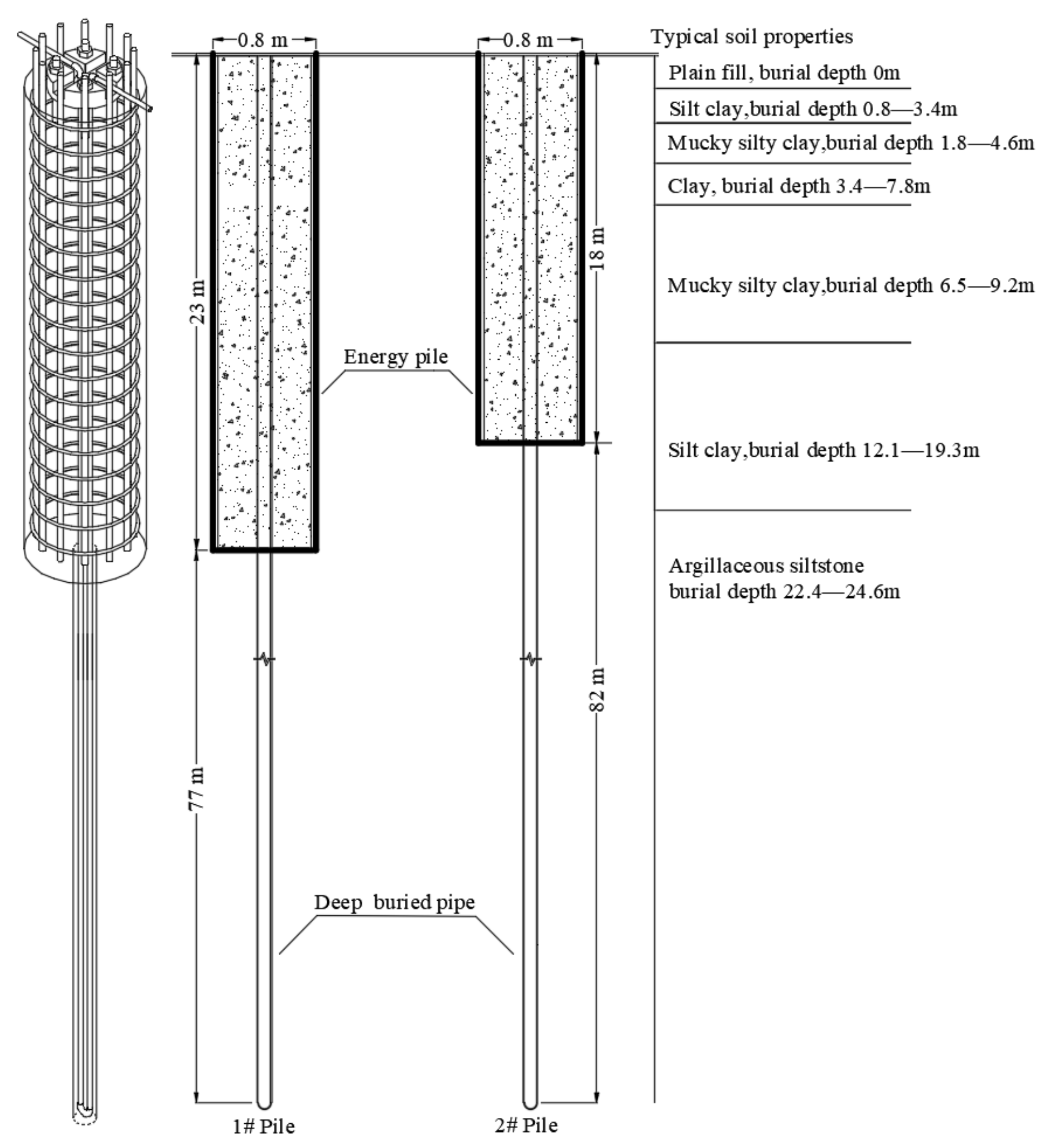
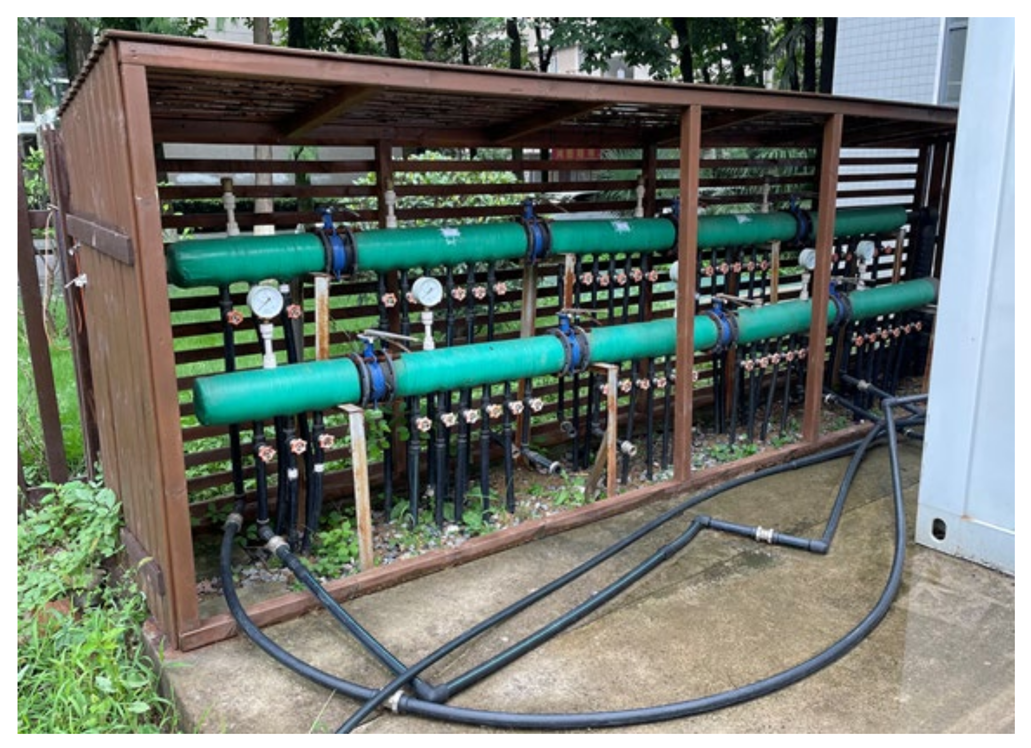
The test base was located at Hubei University of Technology. The site topography was mainly composed of clay, silty clay, muddy clay, and strongly weathered argillaceous siltstone, of which the clay layer was approximately 24 m. The distribution of the soil layer is shown in Figure 1. There were two deep buried pipe energy piles in the test base, the diameter of the pile was 800 mm, and the pile lengths were 23 and 18 m, which are recorded as piles #1 and #2, respectively. After completion of pile construction, holes were drilled in the center of the pile with a hole diameter of 150 mm, a drilling depth of 100 m. The heat exchange pipe diameter was 25 mm. The double U parallel arrangement was adopted, and the distributed temperature measuring optical fiber was bound on the pipe wall. After completion, the U-shaped heat exchange pipe was put into the heat exchange well and backfilled with fine sand. In this test, we set up a water collector and separator device to control the connection of different pipelines, as shown in Figure 2; after connecting the heat exchange pipe to the water collector and separator device, the water collector and separator device were then connected with the thermal response instrument to form a circulating loop, in which the thermal response instrument can control the inlet water temperature and flow rate and monitor the process. At the same time, we used a distributed temperature sensing optical fiber monitoring system (DTS) to measure the temperature of the heat exchanger wall and analyze the temperature of the inlet and outlet water pipe changes with time, its temperature resolution can be accurate to 0.05 k and the default setting of the system is to form a temperature measuring point every 1 m along the optical fiber path to monitor and record the temperature data. At the beginning of the test, after connecting the temperature measuring optical fiber to the computer, the DTS was opened to set the temperature measuring time interval and other parameters (the temperature measuring interval was set as 5 min in this paper), after setting, the main interface of the system was entered, which displayed the temperature data of each temperature measuring point of the optical fiber at the current time and recorded the data in the background.
2.2. Test Plan
Before the test, the initial formation temperature recorded by DTS was stable at 18.5 °C. The test process is to turn on the thermal response meter to heat the fluid in the tube with constant power for 72 h, wait for 7 days to recover the ground temperature, and perform the next set of tests. During the heating period, DTS was used to measure the temperature. The effects of well depth, pile length, inlet water temperature and flow rate on the heat exchange performance of energy piles are considered in this test. Table 1 shows the in situ heat exchange test scheme of DBP-EP.
When the circulating water in the heat exchange pipe circulates in the buried pipe and exchanges heat with the concrete pile or the soil of the deep well, the temperature of the circulating water changes with time and finally reaches stability. At this time, the temperature difference between the inlet and outlet tends to be stable. According to Formulas (1) and (2), the total heat exchange and unit heat exchange were calculated, and the heat exchange efficiency of DBP-EP analyzed under different variables.
where is the total heat exchange, is the heat exchange rate per unit length (W/m), and is the specific heat capacity of the circulating medium under constant pressure. The circulating medium in this test is water, and the specific heat capacity of water is 4.2 × 10³ J/(kg·°C); is the circulating water volume flow (m3/h), is the density of the circulating fluid (kg/m), and the value is 1000 kg/m3; is between the outlet temperature (Tout) and the inlet temperature (Tin), and L is the length of the heat exchanger (m).
3. Finite Element Numerical Simulation
3.1. Basic Assumptions
In the simulation analysis of DBP-EP, considering the complexity of the deep buried pipe energy pile structure and the instability of soil temperature, the following basic assumptions are made:
- (1)
- The fluid, heat exchange tube, concrete and soil are homogeneous, and their thermal performance is independent of temperature.
- (2)
- The self-weight of the fluid, the contact thermal resistance between the U-shaped pipe wall and pile foundation, the pile foundation and the surrounding soil are not considered.
- (3)
- Assuming that the initial temperatures of the soil and pile foundation are the same, the temperature at the far boundary of the soil remains unchanged.
- (4)
- The influence of groundwater on the heat exchange of energy pile is ignored.
- (5)
- The change of soil temperature along the depth direction is ignored.
- (6)
- The influence of environmental factors on shallow soil temperature is ignored.
3.2. Basic Assumptions
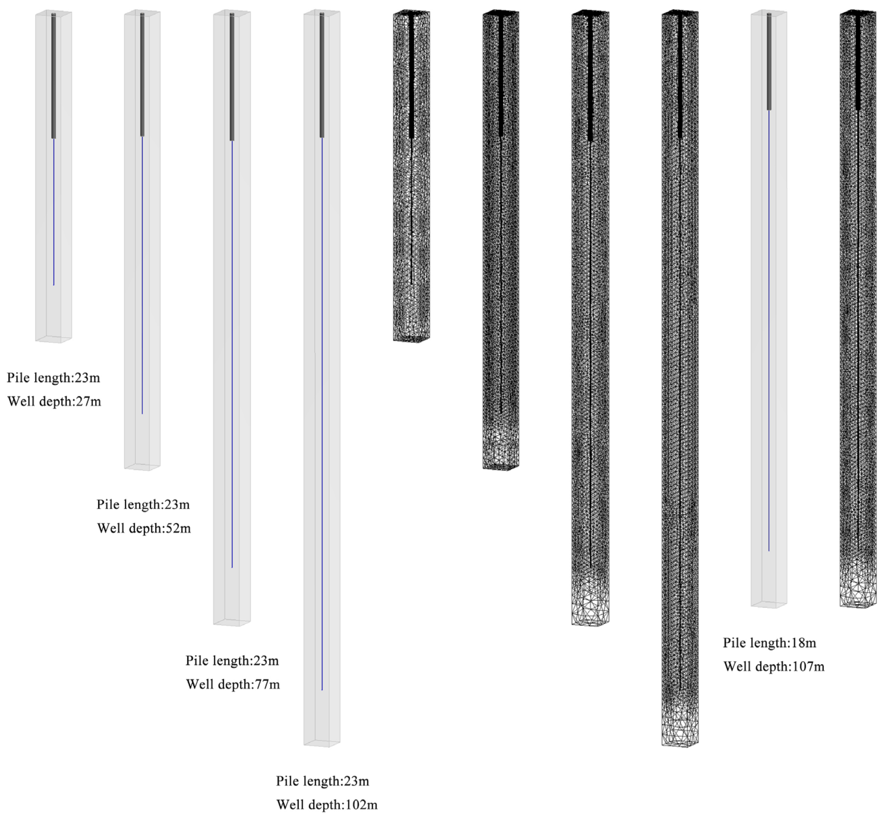
A 1:1 numerical model was established based on the field deep buried pipe energy pile and named pile #1 and pile #2 according to the corresponding pile length. The model consisted of heat exchange tubes, piles, and soil; the diameter of the energy pile was 800 mm, the lengths of the piles were 23 and 18 m, the depths of the soil were 60, 85, 110 and 135 m, and the depths of the heat exchange tubes were 50, 75, 100 and 125 m, the diameter of the heat exchange tube was 25 mm, and the spacing between branch tubes was 60 mm. The overall structure and grid division of the energy pile are shown in Figure 3. Pile #1 is different from pile #2 only in length, the figure only shows the model and grid when the length of the pile #2 deep well is 100 m.
4. Result Analysis and Discussion
4.1. Well Depth
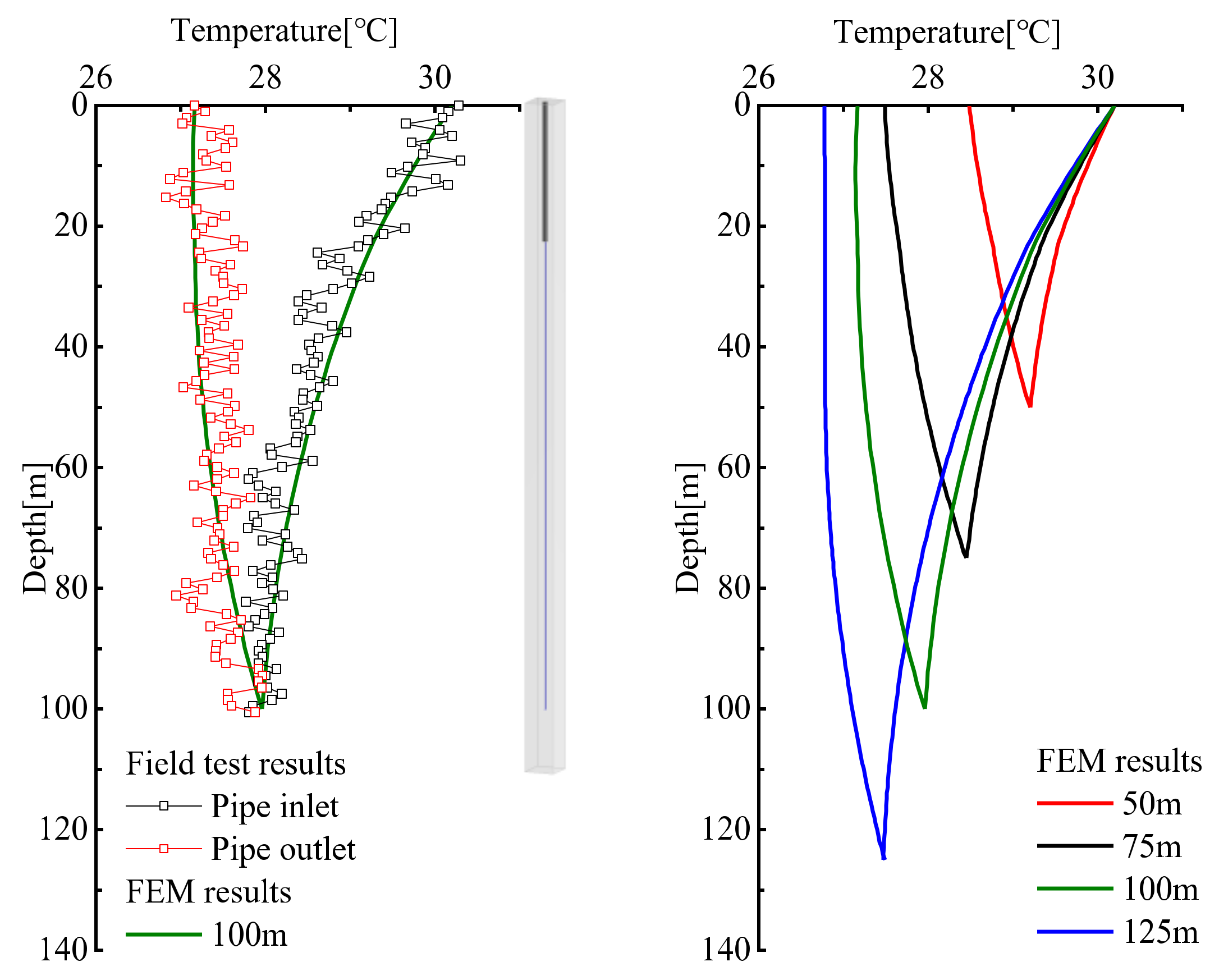
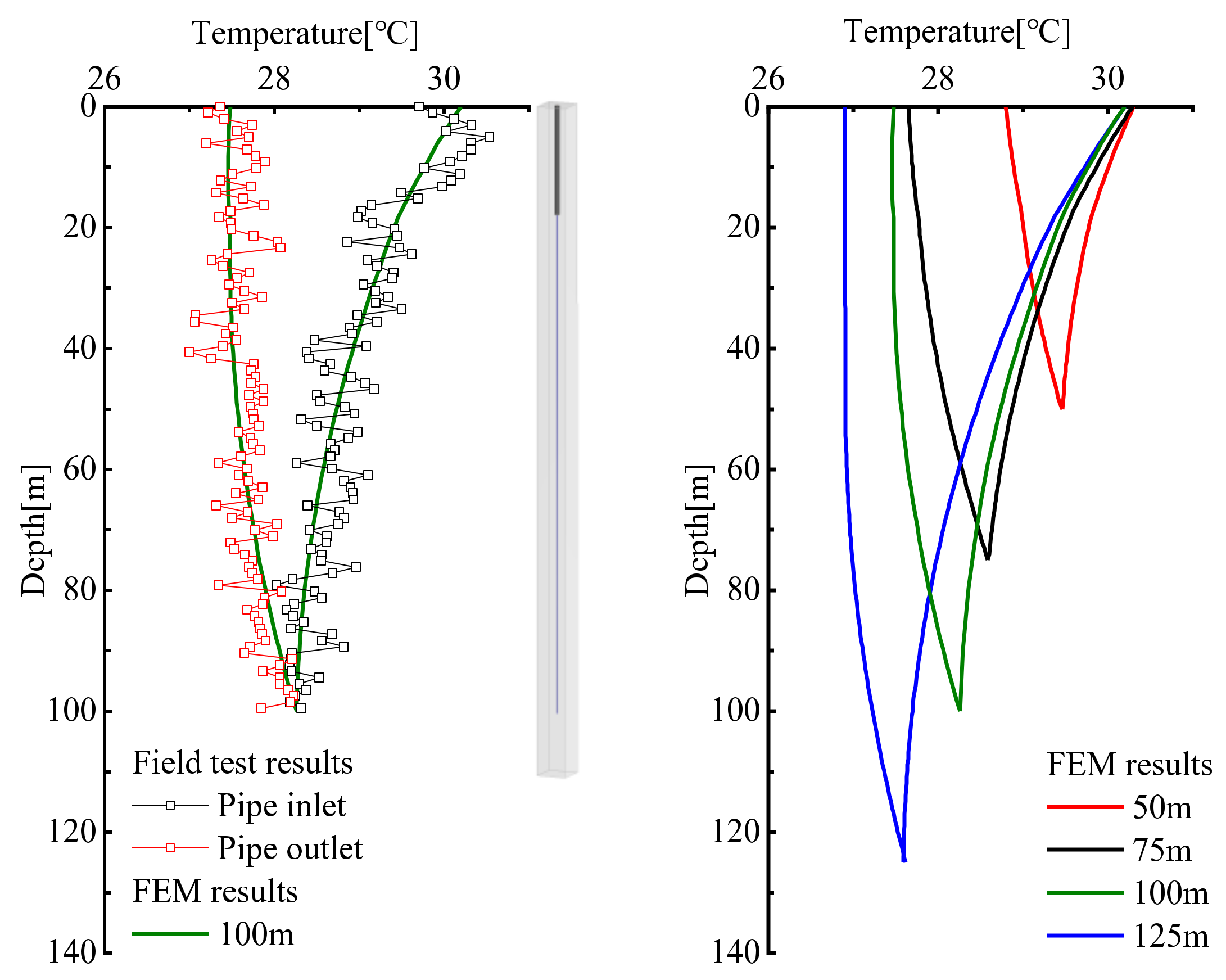
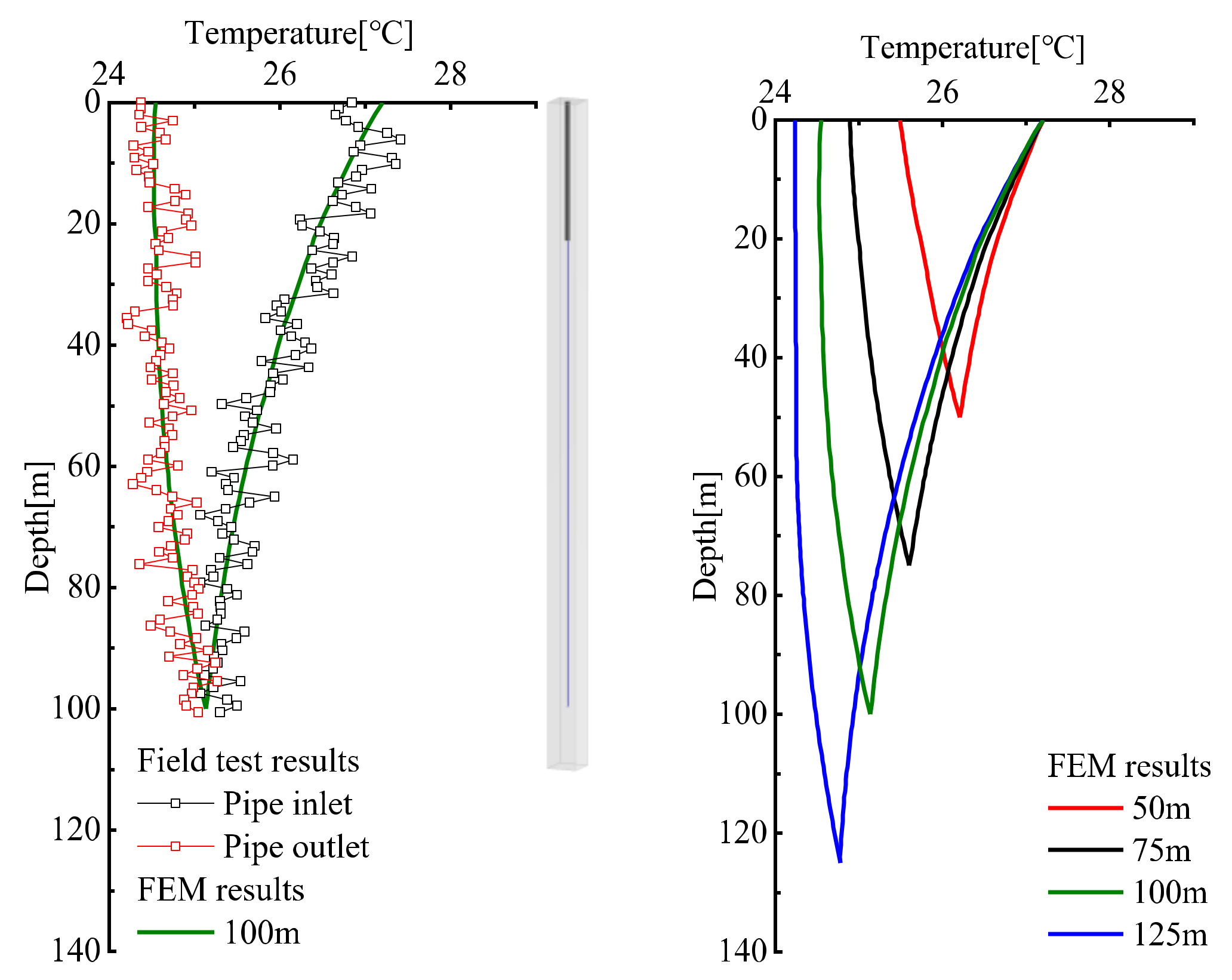
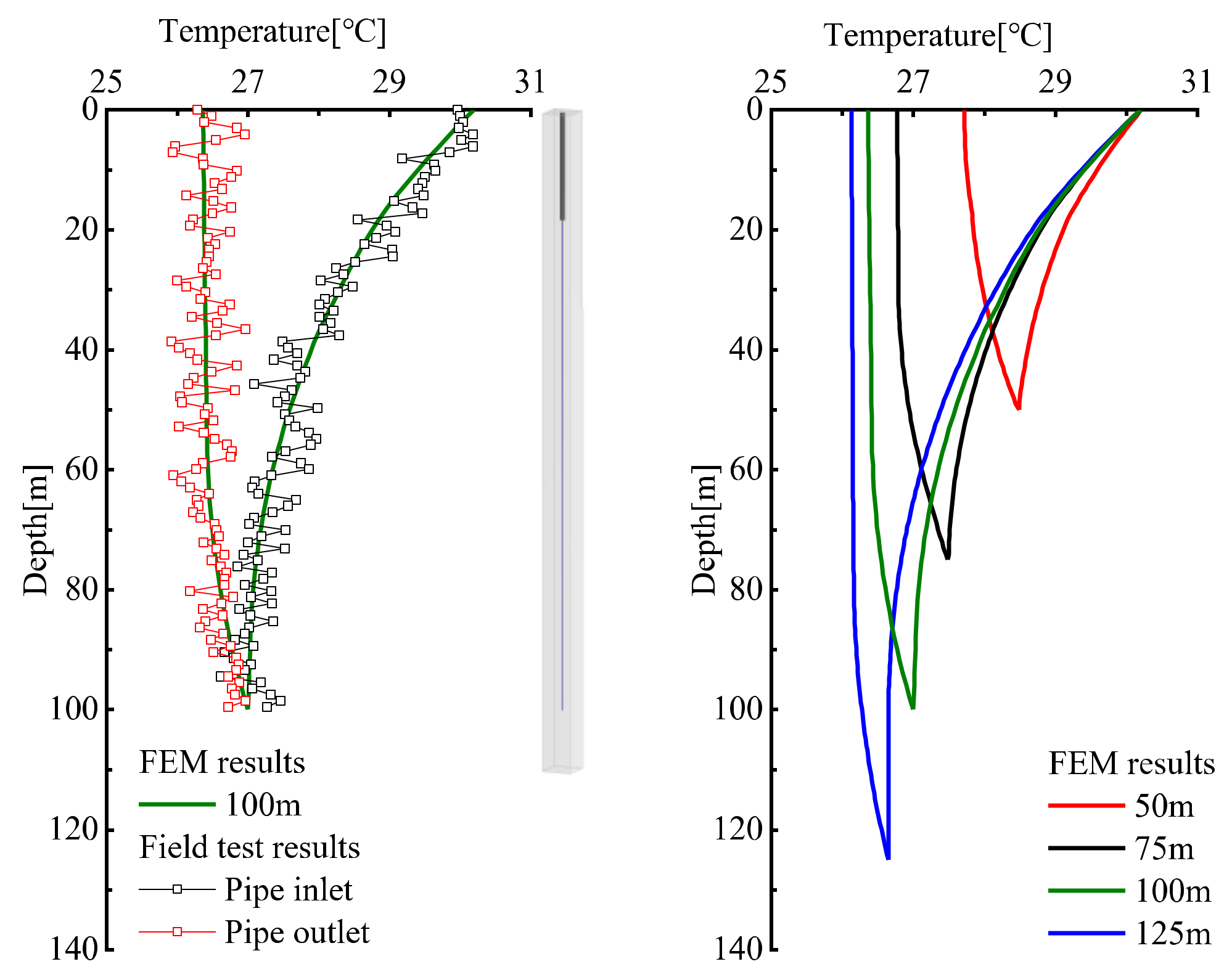
The temperature distributions of the inlet and outlet pipes of the energy piles in the field test 2 and simulation tests under different well depths (tests 6–9) are shown in Figure 4. The field test used pile #1 with a well depth of 100 m. The field test and simulation results are relatively close. During the operation of the energy pile, the heat exchange is mainly based on the inlet pipe, the heat exchange path of the pile foundation is heat exchange pipe-sand-concrete, and the heat exchange path of the deep well is heat exchange pipe-sand-oil; the heat flows first exchange heat with the pile foundation. Based on the good thermal conductivity of concrete, the water temperature of the inlet pipe drops faster in the pile foundation part and slower in the deep well part; the temperature difference of inlet pipe is greater than that of the outlet pipe, because the temperature difference between the heat flow in the outlet pipe and the heat exchange medium is small, and the distance between the inlet and outlet pipes is small, leading to thermal interference. When the well depth increases from 50 to 125 m, the temperature difference of the inlet pipe increases, but the increase is small, the temperature difference of the outlet pipe is reduced; the thermal interference phenomenon gradually increases from the bottom of the deep well to the top of the pile foundation and is more obvious in the pile foundation with the increase in the length of the deep well.
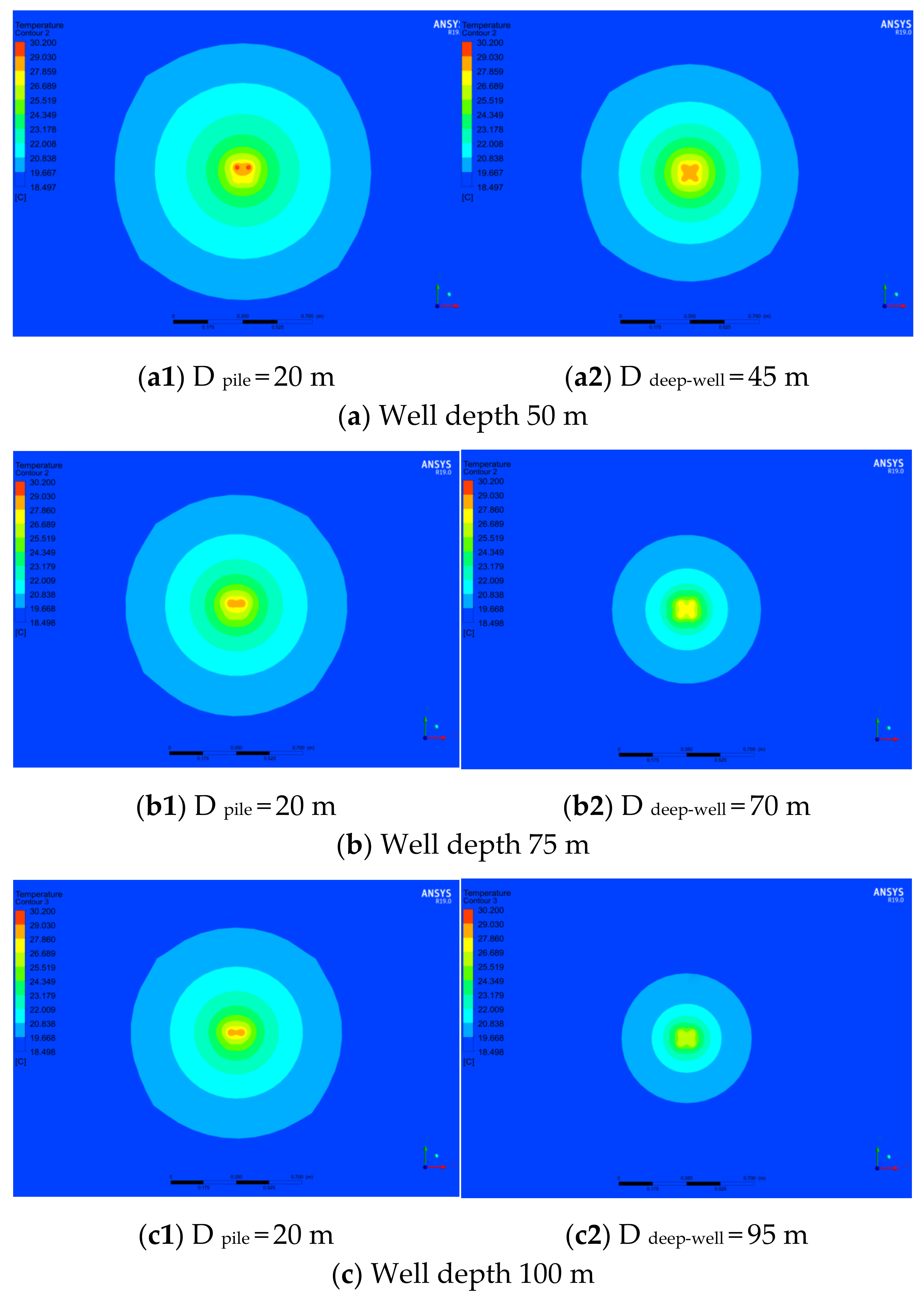
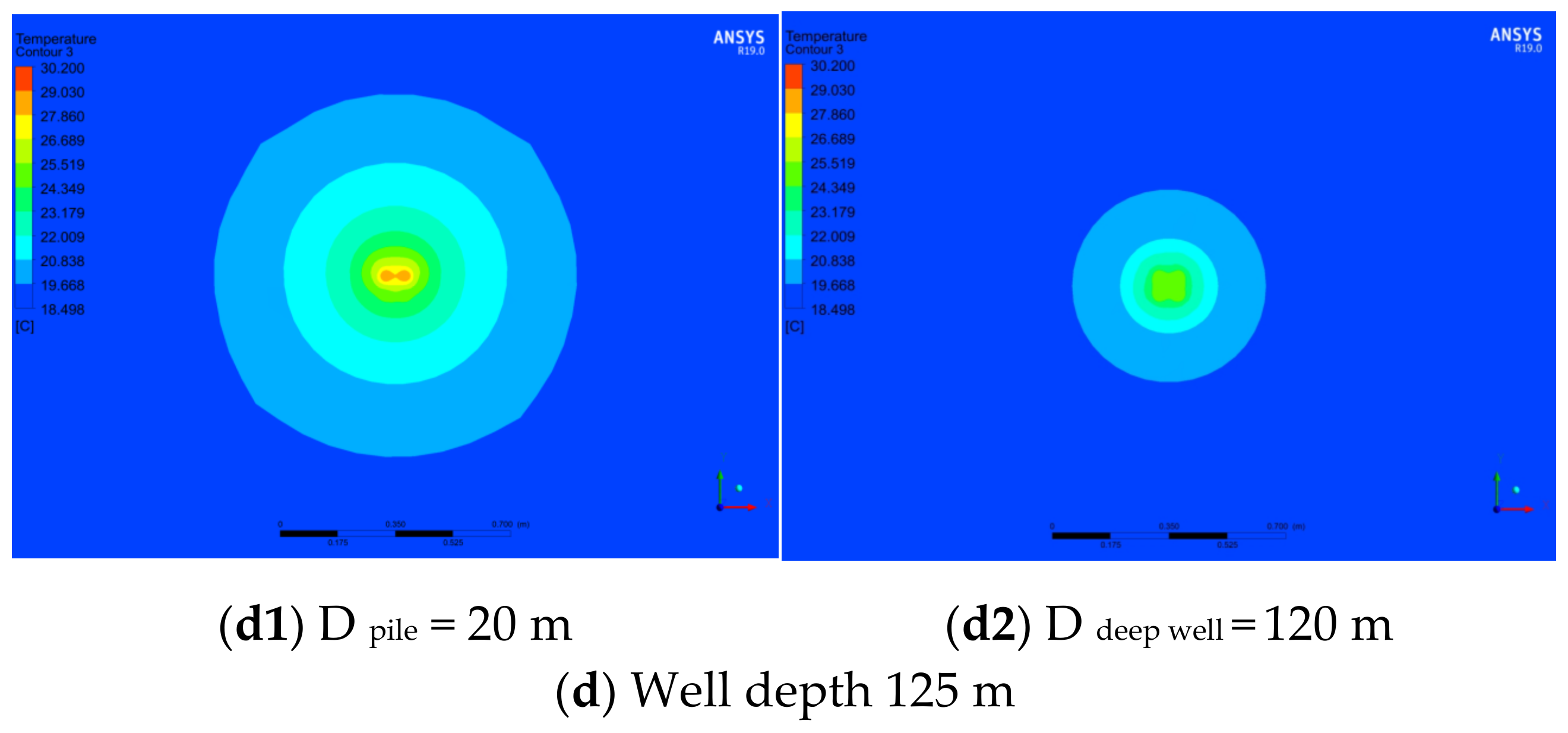
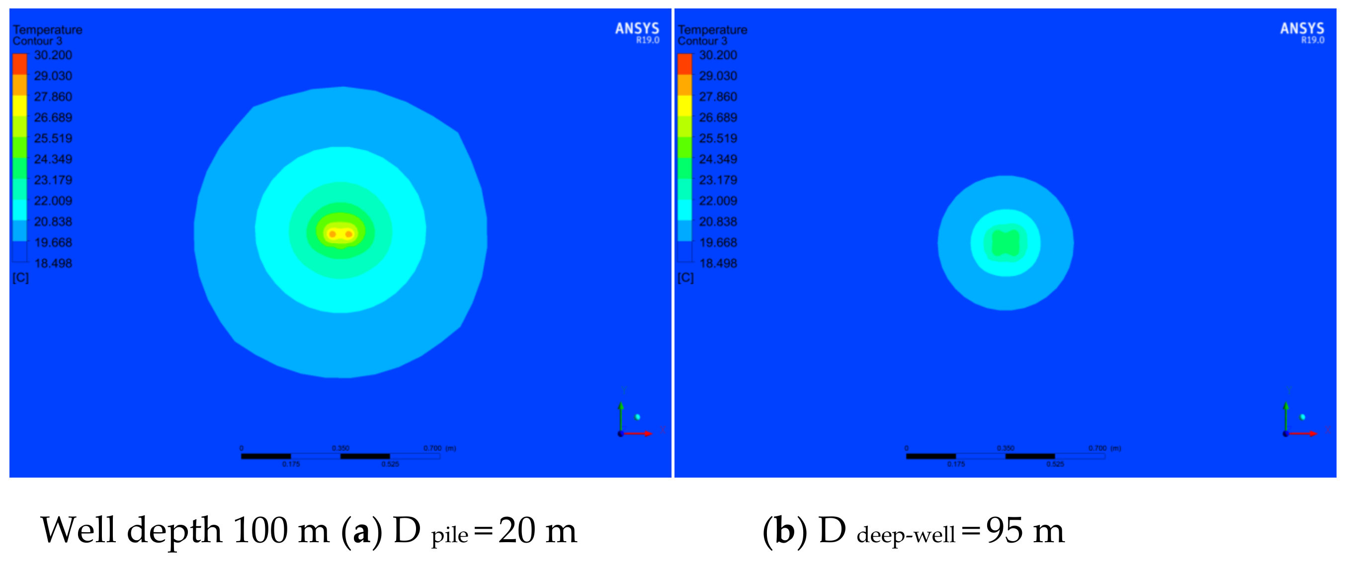
The cloud diagram of the temperature distribution at the pile bottom and deep well bottom of pile #1 under different well depth conditions (tests 6–9) is shown in Figure 5. The isotherm at the base of the pile has a circular dense distribution, and the heat exchange radius is less affected by the well depth, with a change of approximately 1.0 m. The density of the isotherm at the bottom of the deep well decreases, and the heat exchange radius decreases with increasing well depth; when the well depth is 100 m, the heat exchange radius at the bottom is approximately 0.7 m. The analysis shows that when the well depth increases, the temperature at the bottom of the inlet pipe decreases; at the same time, considering that the thermal conductivity of rock and soil is weaker than that of concrete, the heat exchange radius decreases gradually. The temperature distribution cloud diagram of the energy pile is in good agreement with the temperature distribution law of the inlet and outlet pipes mentioned above.
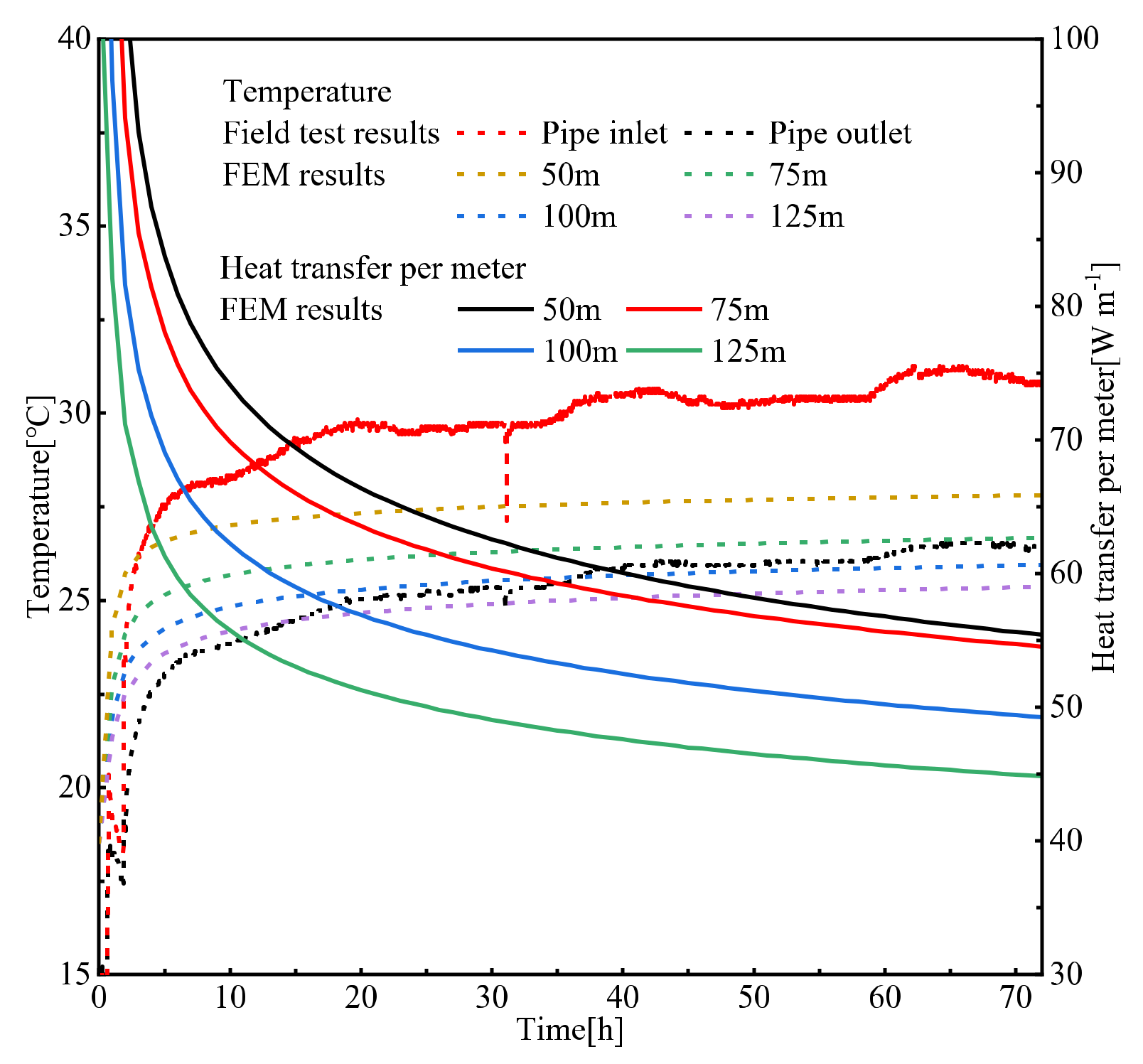
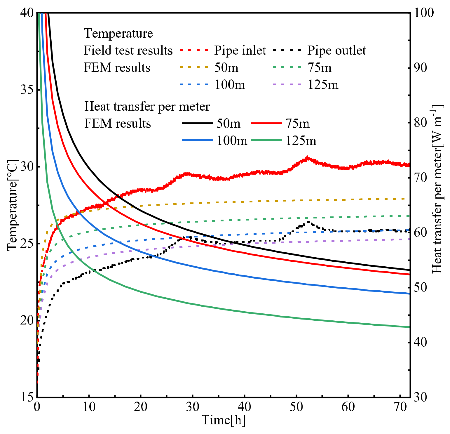
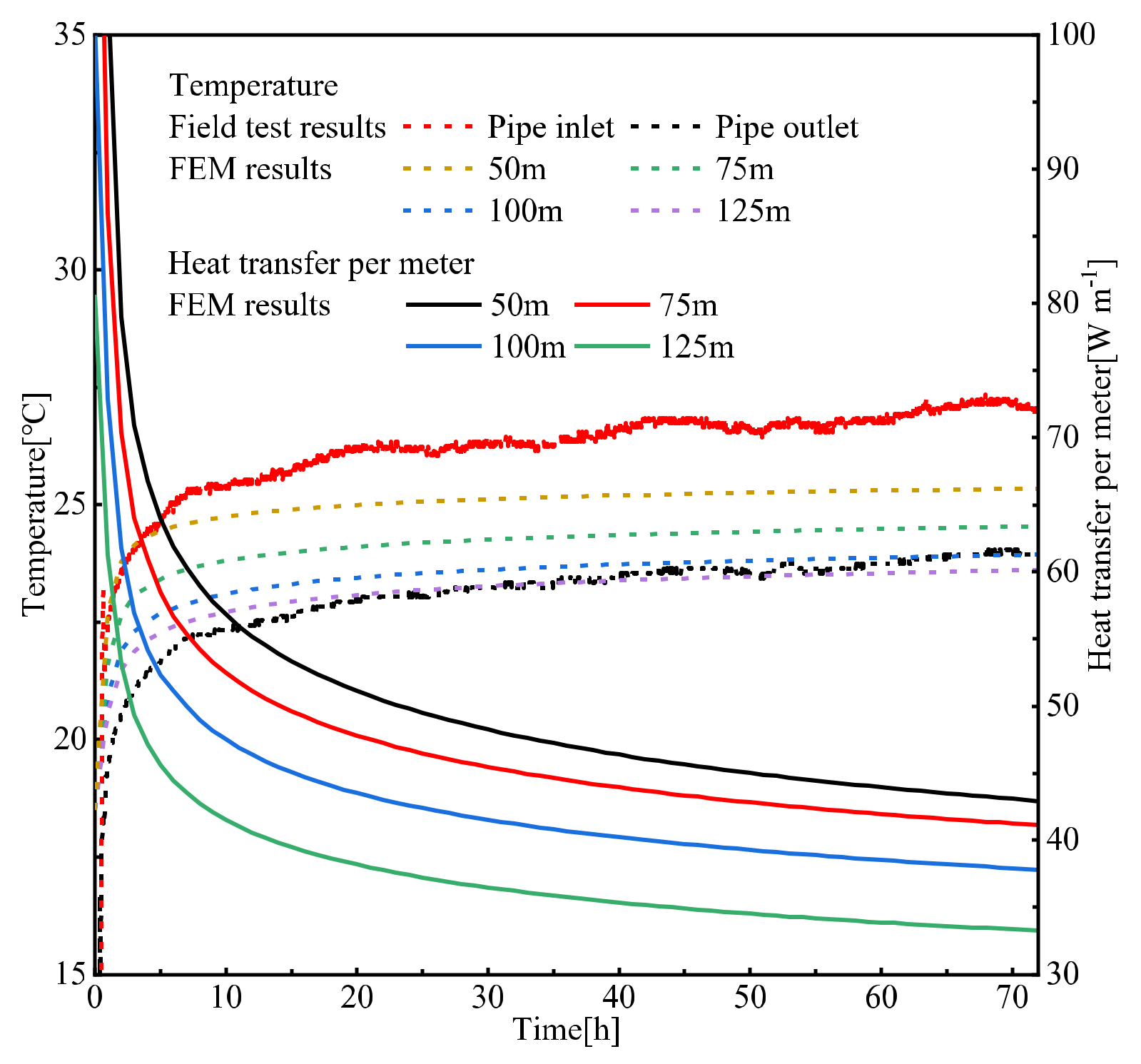
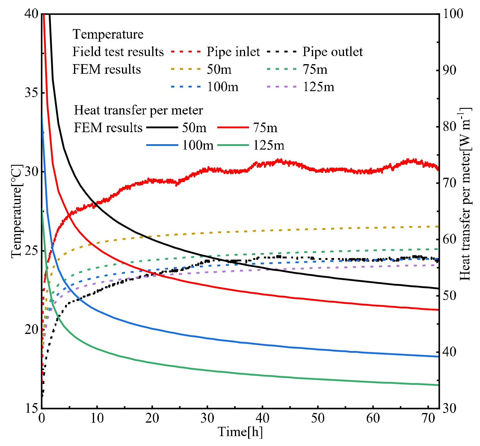
Figure 6 shows the variation in water temperature at the inlet and outlet of the energy pile and unit heat exchange with time under different well depth conditions (tests 2 and 6–9). After heat exchange for 60 h, the inlet and outlet temperatures were 30.2 and 25.8 °C, respectively, and tended to be stable; then, the temperature rebounded. Affected by shallow ground temperature and environmental factors, the import and export temperatures rose slightly. The temperature difference between the inlet and outlet of the energy pile in the field test is 4.4 °C, and 2.4, 3.5, 4.3 and 4.8 °C for the simulation tests, which shows that the increase of well depth can significantly increase the temperature difference between the inlet and outlet, affecting the total heat exchange of the energy pile. On the other hand, it also means the reduction of unit heat exchange, therefore, it is necessary to select a suitable pile-to-well ratio (the ratio of the length of heat exchange pipe between pile foundation and deep well) to obtain the best heat exchange efficiency. The unit heat exchange of the energy pile gradually decreases, tends to be stable with time, is inversely correlated with well depth, and decreases in a nonlinear trend with increasing well depth.
4.2. Pile Length
Figure 7 shows the temperature distribution of the inlet and outlet water pipes of the energy pile in the field test 4 and simulation tests 14–17. There is no obvious change in the overall heat exchange law of the energy pile, but the length of pile #2 is shorter than that of pile #1, which reduces the heat exchange between the heat flow and the pile foundation concrete, the heat exchange effect of the energy pile is also reduced. In the field test, the inlet pipe temperature of the two piles is basically the same around 18 m, then the heat exchange path of the #2 pile changes first, and the deep well begins to exchange heat, at this time, the temperature difference between the inlet pipes of the two piles gradually increases and reaches the maximum at the bottom, affected by the inlet pipe, the outlet pipe temperature difference first increases and then decreases. The outlet pipe temperature differences at the well depth of 50–125 m are 0.2, 0.4, 0.3 and 0.1 °C, respectively, which indicates that the influence of pile length on the heat exchange of the energy pile weakens as the well depth increases.
The cloud diagram of the temperature distribution of pile #2 is consistent with the above law. The variation of outlet water temperature and unit heat exchange of the energy pile with time under different well depths of pile #2 (tests 4 and 14–17) is shown in Figure 8. The temperature difference between the inlet and outlet of the energy pile in the field test was 4.1 °C, the simulation tests are, respectively 2.3, 3.4, 4.2 and 4.6 °C; comparing the two test analyses, when the length of the energy pile increases, the pile foundation carries out more heat exchange, and obtains a lower outlet water temperature, thereby increasing the energy pile heat exchange; however, due to the small difference in the length of the two piles in this test, the heat exchange decreases along the pile foundation. The difference in unit heat exchange is small, but the pile length has a relatively obvious influence on the heat exchange of the energy pile.
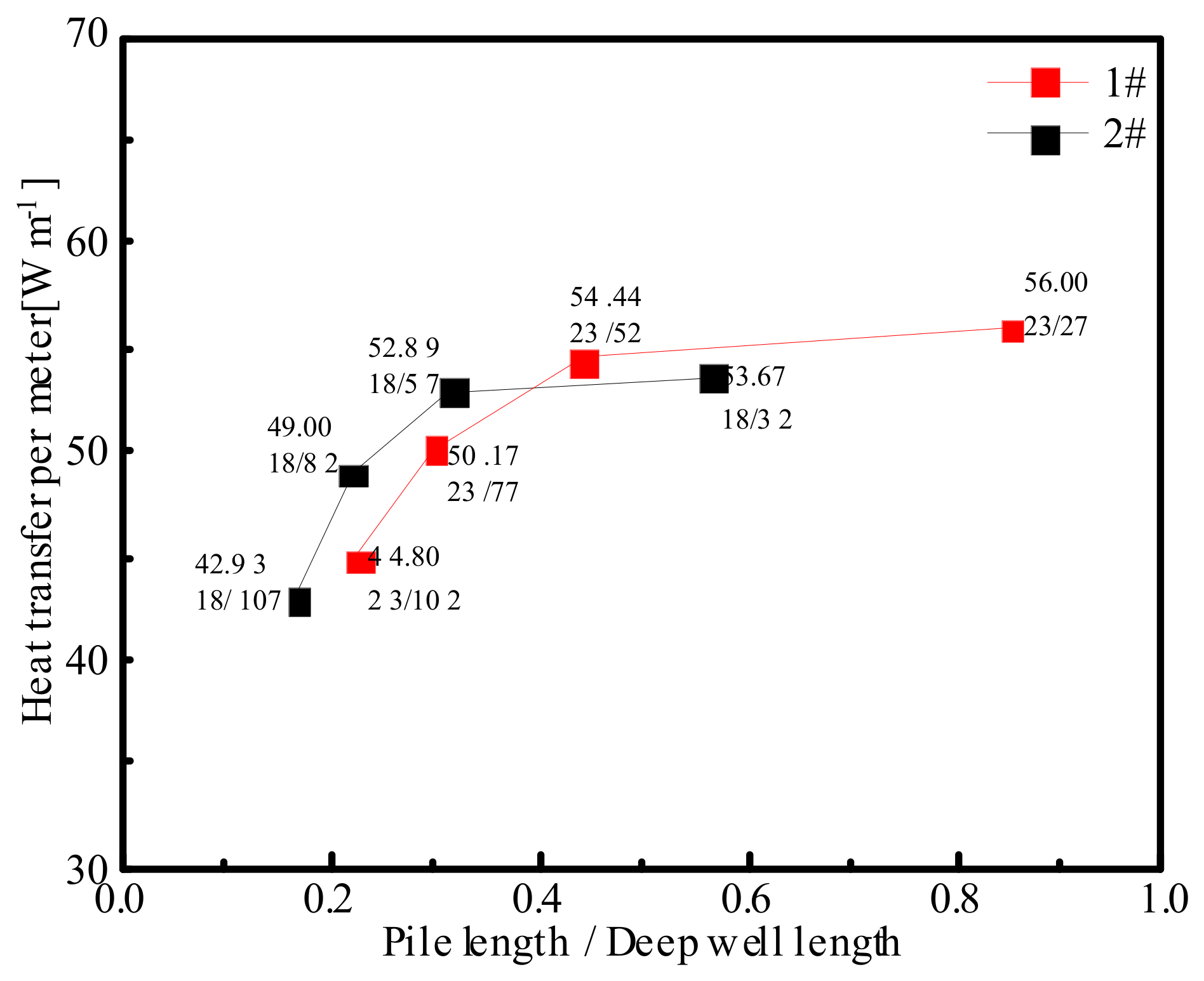
Figure 9 shows the distribution of the unit heat exchange of energy piles with different pile-to-well ratios. The pile-to-well ratio is positively correlated with the unit heat exchange of energy piles and changes in a nonlinear trend, but the correlation between the pile-to-well ratio and the unit heat exchange gradually decreases as the pile-to-well ratio increases. The analysis shows that the high heat exchange per unit is not based on the large temperature difference between the inlet and outlet of the energy piles but is due to the short length of the deep well; reducing the pile-to-well ratio means increasing the depth of the well, but the heat exchange of the energy piles gradually decreases along the deep well, resulting in a small increase in the temperature difference between the entrance and exit of the energy piles but excessively long well depths, this is the main reason for nonlinear changes. Drawing the pile-to-well ratio curve based on the previous two sets of tests, when the pile-to-well ratio is approximately 0.3–0.4, the unit heat exchange reaches the optimal value. In summary, it can be concluded that the ratio of pile length to deep well length is not affected by monotonic changes, calculating the effect of different pile-to-well ratios on the heat exchange efficiency will provide the best solution for structural design.
4.3. Inlet Water Temperature
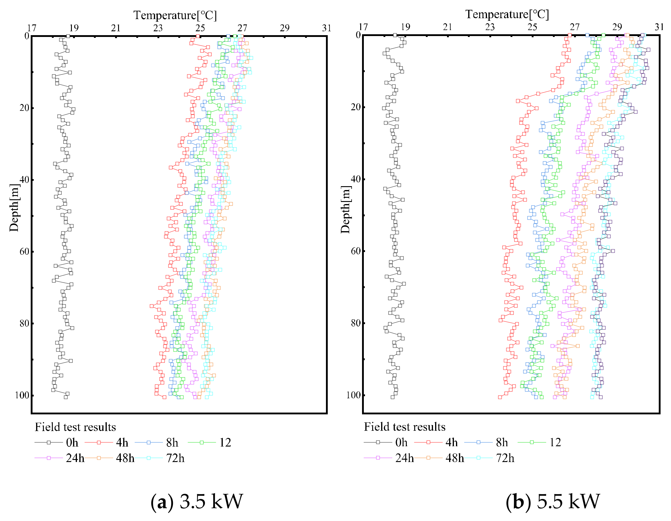
The temperature distribution of the water inlet pipe under different heating powers (test 1 and 2) of pile #1 is shown in Figure 10. The heating power is 3.5 kW, the temperature of the inlet pipe rises uniformly and changes slightly, the temperature of the 5.5 kW inlet pipe rises unevenly, and the temperature of the heat exchange pipe in the pile foundation is significantly higher than that in the deep well at the initial stage of heat exchange. This is because early heat exchange occurs mainly in the pile foundation, and the effect of the deep well participating in heat exchange is not obvious. Comparing the temperature changes of the heat exchange tubes under different heating powers, when the heating power is low, the operation of the energy pile is more likely to reach a stable state.
Figure 11 shows the temperature distribution of the inlet and outlet water pipes of the energy piles (tests 1 and 10–13). When exploring the heat exchange effect of energy piles with different inlet water temperatures, comparative tests (tests 2 and 6–9) were selected. The analysis shows that the higher the inlet water temperature is, the greater the temperature difference between the heat flow in the heat exchange tube and the heat exchange medium, and the more obvious the heat exchange effect, after the well depth increases, this phenomenon is more obvious in the pile foundation, because when the heat flow temperature is high, heat exchange occurs mainly in the pile foundation; entering the deep well, the heat flow temperature decreases and the heat exchange effect is weakened, so the heat exchange effect is not as obvious as that of the pile foundation; in addition, although the low inlet water temperature can weaken the thermal interference phenomenon, the overall temperature of the energy pile is low at this time, the outlet pipe is less affected by the inlet pipe, but the heat exchange level is still low.
When the inlet water temperature is 27.2 °C, the changes in inlet and outlet water temperature and unit heat exchange of energy pile #1 with time under different well depth conditions (tests 1 and 10–13) are shown in Figure 12. The temperature difference between the inlet and outlet of the energy pile in the field test is 3.4 °C, and the simulation test is 1.9, 2.7, 3.3 and 3.6 °C, respectively, the comparison with Figure 5 (tests 2 and 6–9) shows that the inlet water temperature can significantly affect the heat exchange effect of the energy pile, and that the temperature difference between the heat flow and heat exchange medium (concrete, rock-soil) is the main factor affecting heat exchange, at the same time, the inlet water temperature has a significant effect on the unit heat exchange.
The test shows that the inlet water temperature has a positive effect on the operation of the energy pile, which can simultaneously produce more heat exchange; it should be noted that the deep well is too long, it is not conducive to the improvement of the heat exchange effect; rather, the heat exchange effect of the outlet pipe decreases greatly with increasing well depth and leads to an increase in economic costs during construction.
4.4. Flow Rate
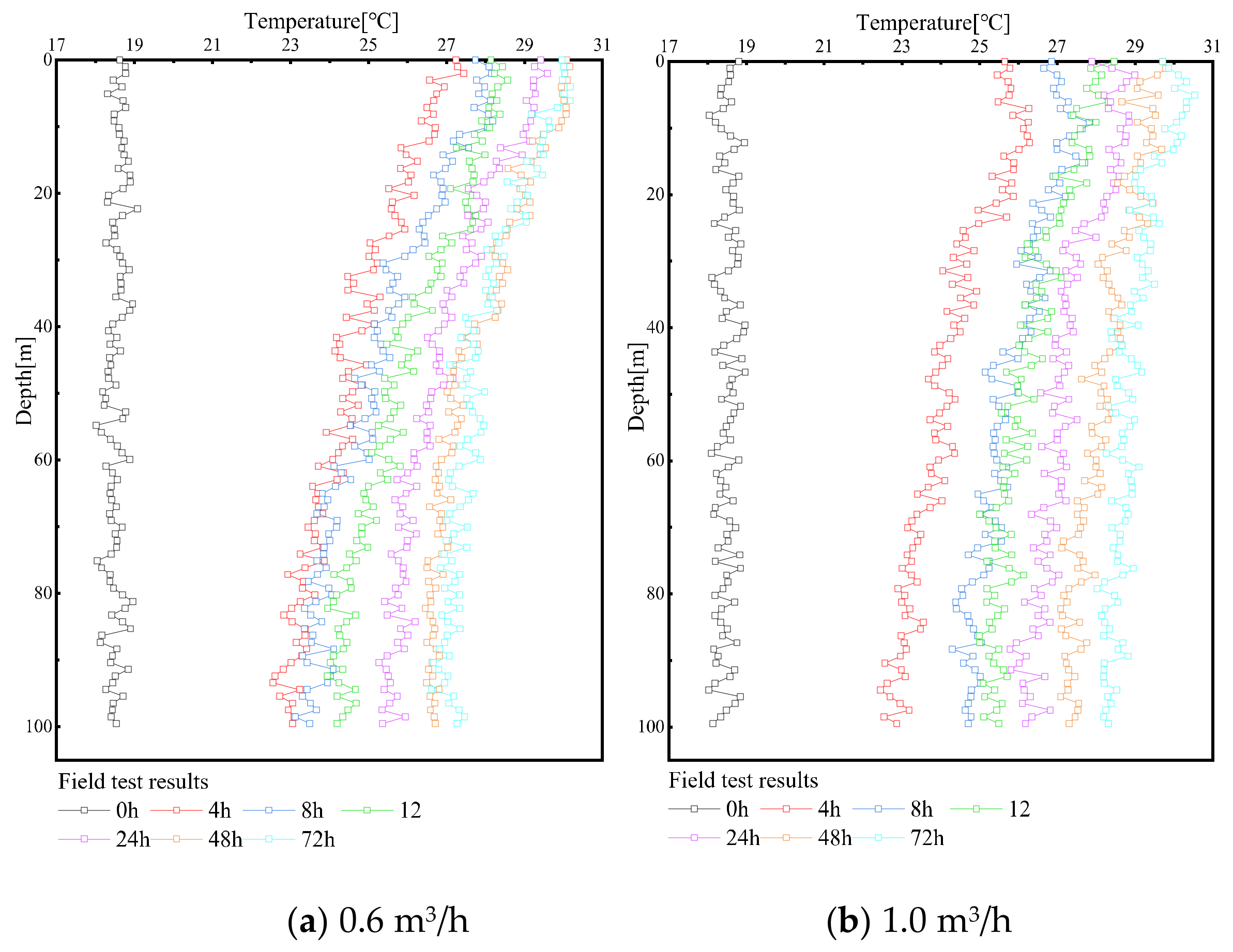
The variation in the inlet pipe temperature of the energy pile with time under different flow rates (tests 4 and 5) is shown in Figure 13. This test controls the flow rate to achieve the purpose of controlling the flow rate. When the flow rate is 0.6 m3/h, the temperature of the inlet pipe changes intensively with time and decreases greatly along the deep well. The flow rate in the early stage of operation is low, and the energy pile can carry out more heat exchange, resulting in no significant increase in the temperature of the inlet pipe; when the flow rate is 1.0 m3/h, the temperature of the inlet pipe has a significant rise, and the temperature change downward along the heat exchange pipe is small; the comparative test shows that when the flow is low, the early heat exchange effect of energy pile is more obvious, and tends to stabilize faster.
The temperature distribution of the inlet and outlet pipes of pile #2 (tests 5 and 18–21) under different well depth conditions is shown in Figure 14. When the flow rate is 0.6 m3/h, the decrease in inlet pipe temperature increases with increasing well depth, but the slight decrease in the temperature of the heat exchange pipe at the bottom of the deep well cannot be ignored, because when the flow rate is low, the heat exchange effect of the pile foundation and the upper part of the deep well is significant, resulting in a temperature difference that is too small between the lower heat exchange pipe of the deep well and rock–soil, this leads to a decrease in the heat exchange effect, this phenomenon is more significant with increasing well depth, therefore, when the flow rate is low, excessively long well depth is avoided. At the same time, affected by the water inlet pipe, the temperature change of the outlet pipe is small and mainly concentrated in the lower part of the deep well, which is due to the strong thermal interference of the outlet pipe caused by the high temperature around the pile foundation and the upper deep well.
The cloud diagram of the temperature distribution for the energy pile foundation and deep well bottom in test 20 is shown in Figure 15. Compared with Figure 5c, when the flow rate is low, the temperature of the heat exchange tube decreases faster, which results in a lower temperature at the pile tip and a sparse isotherm; the heat exchange radius at the bottom of the deep well decreases obviously, and this phenomenon becomes more obvious with increasing well depth, a heat exchange radius that is too small causes a poor heat exchange effect, therefore, when energy piles are operated at low flow rates, the selection of long deep wells should be avoided, which will further reduce the overall heat exchange effect of energy piles.
When the flow is 0.6 m3/h, the changes in water temperature and unit heat exchange at the inlet and outlet of pile #2 with time under different well depths are shown in Figure 16. In the field test 5, the temperature difference between the inlet and outlet of the energy pile is 5.7 °C, and 3.7, 5.1, 5.6 and 6.1 °C for the simulation test (tests 18–21), the results show that within a certain range, the lower the flow rate is, the greater the temperature difference between the inlet and outlet of the energy pile. By exploring the relationship between the unit heat exchange and the length of the deep well, the increase in well depth will work together with the flow rate to reduce the heat exchange effect of the energy pile, if only considering the summer to obtain a lower outlet water temperature, the heat exchange can be ignored, the demand for heat exchange in winter requires reasonable flow and well depth. By comparing the unit heat exchange with Figure 8 (tests 4 and 14–17), we explored the influence of different flow rates on the heat exchange effect of the energy pile, the analysis shows that when the energy pile operates at a low flow rate, a larger temperature difference between the inlet and outlet can be obtained, however, according to Formulas (1) and (2), the flow rate also affects the calculation of heat exchange, through calculation, it can be known that when the flow is within a certain range, the unit heat exchange increases with increasing flow.
4.5. Comparison and Optimization
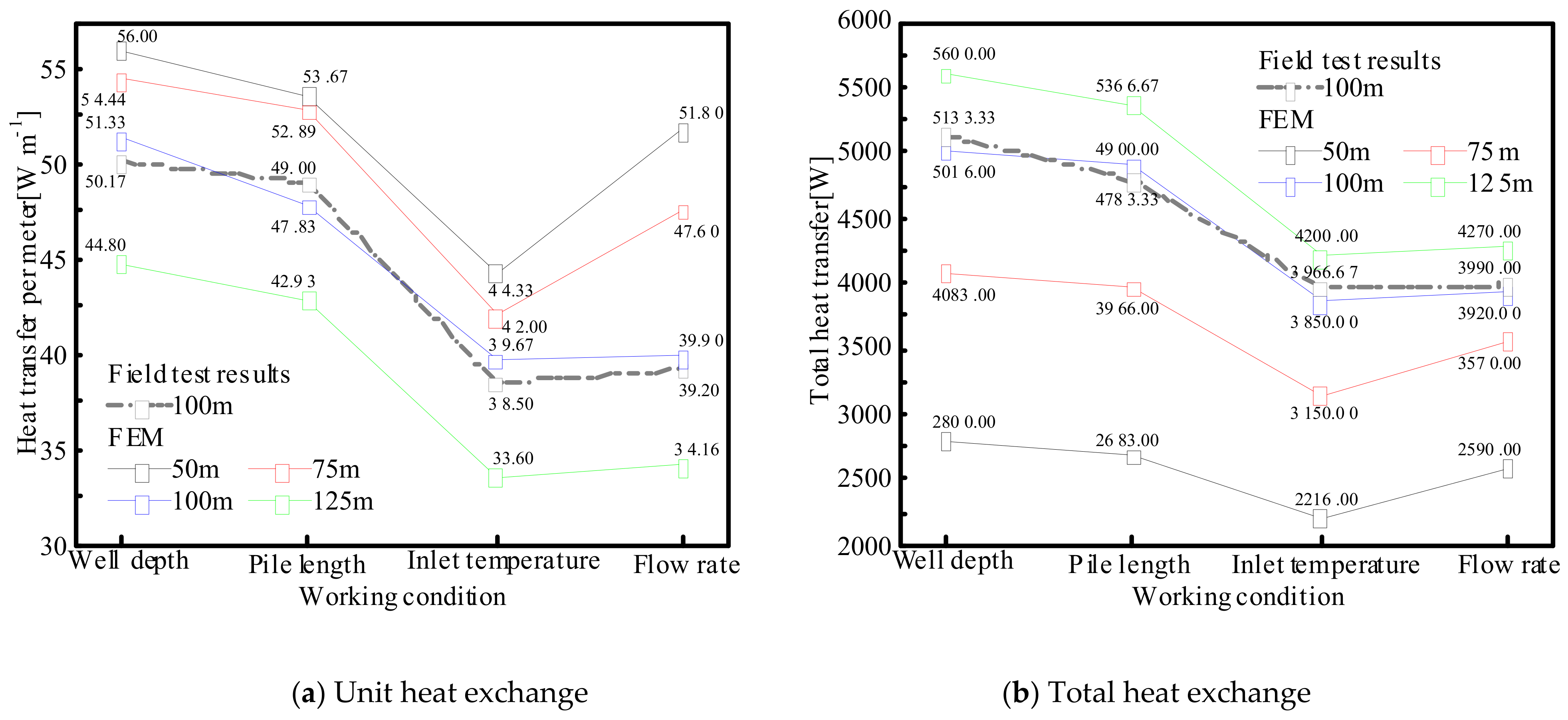
The structure of the new deep buried pipe energy pile (DBP-EP) is flexible, and the design parameters can be selected according to the heat exchange demand to realize efficient and economic utilization of geothermal resources. The calculation results of the unit and total heat exchange of the energy pile are shown in Figure 17. The change trend of the energy pile heat exchange under various heat exchange conditions is approximately the same and does not change with the length of the deep well, but the unit and total heat exchange of the energy pile show the opposite change trend with the increase (decrease) in the deep well length.
For the heat exchange effect of energy piles under the joint action of pile length and well depth, combined with the temperature distribution law and heat exchange analysis of energy piles, the pile length has a great impact on the heat exchange effect of energy piles, but the increase in well depth can further improve the heat exchange effect of energy piles and weaken the impact of pile length on the heat exchange effect of energy piles; based on this, according to the relationship between the pile diameter ratio and unit heat exchange, when the pile-to-well ratio is approximately 0.3–0.4, the heat exchange of the energy pile reaches the optimal value.
According to the analysis of the unit and total heat exchange of the energy pile under different heat exchange conditions, the temperature and flow rate have the most obvious impact on the heat exchange effect of the energy pile, but the flow rate should be set according to the deep well with reasonable length, therefore, when determining the operation parameters of energy piles, the pile well ratio should be given priority before setting the flow.
By exploring the heat exchange effect of deep buried pipe energy piles under different influencing factors, the inlet water temperature, well depth, flow and pile length have a significant impact on the heat exchange efficiency of energy piles, but the degree of impact gradually weakens.
5. Conclusions
This paper conducted field and simulation tests on the heat exchange of deep buried pipe energy piles, analyzed the heat exchange law of deep buried pipe energy piles under four different influencing factors and obtained the following conclusions:
- (1)
- An increase in well depth can weaken the influence of pile length on the heat exchange effect of energy piles, so the pile well ratio is an important factor affecting the heat exchange effect of energy piles. Through analysis, it is found that the best benefit can be obtained when the pile-to-well ratio is approximately 0.3–0.4.
- (2)
- The inlet water temperature is the most significant factor affecting the heat exchange effect of energy piles. When the inlet water temperature is low, the heat exchange tube temperature rises evenly, and the time to reach the stable state is short. When the inlet water temperature is high, it shows the opposite trend; at the same time, the change in inlet water temperature has little effect on the heat exchange radius of the energy pile.
- (3)
- The flow rate has a significant impact on the heat exchange effect of the energy pile, but the pile-to-well ratio should be given priority when determining the operating parameters of the energy pile, and then the flow should be set reasonably. If only the lower outlet water temperature is considered in summer, the pile-to-well ratio can be reduced.
- (4)
- By exploring the heat exchange effect of deep buried pipe energy piles under different influencing factors, it is found that the influence of inlet water temperature, well depth, flow and pile length on the heat exchange efficiency of energy piles gradually weakens.
- (5)
- The long length of deep well and the spacing of heat exchange tubes will aggravate the thermal interference of pile foundation and the upper part of deep well, based on the pile well ratio and the selection of backfill materials, the thermal interference phenomenon can be appropriately reduced.
This paper explored the influence of different influencing factors on the heat exchange effect of deep buried tubular energy piles. Due to the long duration of field tests and the influence of season and other factors, multiple groups of repeated tests cannot be carried out in a short time to improve the test accuracy. In order to improve the research results, more accurate test data can be obtained by increasing the time of a single test and the times of the same test, at the same time, numerical simulation can further improve the consistency of simulation data trend by refining the soil layer. As presented in this paper, research on the thermal interference of inlet and outlet pipes can be carried out in the follow-up, and the heat exchange effect of energy pile can be improved by lowering the heat exchange pipe at the same time; alternatively, the heat exchange effect of pile groups can be explored.
Author Contributions
Methodology, Z.C., B.W.; software, B.W., J.W.; validation, Z.C., J.W. and B.W.; formal analysis, B.W.; investigation, B.W.; resources, Z.C., H.X.; data curation, Z.C.; writing—original draft preparation, B.W.; writing—review and editing, Z.C., L.Z.; visualization, Z.C., B.W.; supervision, Z.C., L.Z.; project administration, Z.C., L.Z., H.X.; funding acquisition, Z.C., H.X. All authors have read and agreed to the published version of the manuscript.
Funding
The work presented in this paper was supported by the National Natural Science Foundation of China (No. 51808203).
Conflicts of Interest
The authors declare no conflict of interest.
References
- Hamada, Y.; Saitoh, H.; Nakamura, M.; Kubota, H.; Ochifuji, K. Field performance of an energy pile system for space heating. Energy Build. 2007, 39, 517–524. [Google Scholar] [CrossRef]
- Brandl, H. Energy foundations and other thermo-active ground structures. Géotechnique 2006, 56, 81–122. [Google Scholar] [CrossRef]
- Mao, J.F.; Pan, D.; Geng, S.B.; Chen, S.Y. Research on Application of GSHP in Underground Engineering and Its Prospects. Chin. J. Undergr. Space Eng. 2015, 11, 252–256. [Google Scholar]
- Zhang, L.; Chen, S.; Zhang, C. Geothermal power generation in China: Status and prospects. Energy Sci. Eng. 2019, 7, 1428–1450. [Google Scholar] [CrossRef] [Green Version]
- Xu, Y.S.; Wang, X.W.; Shen, S.L.; Zhou, A.N. Distribution characteristics and utilization of shallow geothermal energy in China. Energy Build. 2020, 229, 110479. [Google Scholar] [CrossRef]
- Liu, Y.; Zhao, J.; Li, Y. Effect of drilling depth on performance of ground source heat pump system. Acta Energ. Sol. Sin. 2015, 36, 2584–2589. [Google Scholar]
- Wu, D.; Kong, G.Q.; Liu, H.L.; Jiang, Q.; Yang, Q.; Kong, L. Performance of a full-scale energy pile for underground solar energy storage. Case Stud. Therm. Eng. 2021, 27, 101313. [Google Scholar] [CrossRef]
- Lee, S.; Park, S.; Kim, D.; Ahn, D.; Choi, H. Dual performance of novel steel pipe heat exchangers equipped in cast-in-place energy pile. Energy Build. 2021, 234, 110725. [Google Scholar] [CrossRef]
- Xiao, H.L.; Chen, Z.; Xiao, Y.; Ma, Q.; Que, M.K. Back-Drilling Deeply Buried Pipe Type Pouring Type Energy Pile Heat Exchange System and Construction Method. Patent CN108444121A, 24 August 2018. [Google Scholar]
- Gao, J.; Zhang, X.; Liu, J.; Li, K.S.; Yang, J. Numerical and experimental assessment of thermal performance of vertical energy piles: An application. Appl. Energy 2008, 85, 901–910. [Google Scholar] [CrossRef]
- Du, T.; Li, Y.B.; Bao, X.H.; Tang, W.C.; Cui, H.Z. Thermo-Mechanical Performance of a Phase Change Energy Pile in Saturated Sand. Symmetry 2020, 12, 1781. [Google Scholar] [CrossRef]
- Mandal, M.; Bag, R. Effect of pile and heat exchanger properties on total heat extraction of an energy pile—A numerical study. In Proceedings of the 2nd International Conference on Energy Geotechnics (ICEGT 2020), La Jolla, CA, USA, 20–23 September 2020; Volume 205, p. 05024. [Google Scholar] [CrossRef]
- Jalaluddin; Miyara, A.; Tsubaki, K.; Inoue, S.; Yoshida, K. Experimental study of several types of ground heat exchanger using a steel pile foundation. Renew. Energy 2011, 36, 764–771. [Google Scholar] [CrossRef]
- You, T.; Li, X.T.; Cao, S.L.; Yang, H.X. Soil thermal imbalance of ground source heat pump systems with spiral-coil energy pile groups under seepage conditions and various influential factors. Energy Convers. Manag. 2018, 178, 123–136. [Google Scholar] [CrossRef]
- Carotenuto, A.; Marotta, P.; Massarotti, N.; Mauro, A.; Normino, G. Energy piles for ground source heat pump applications: Comparison of heat transfer performance for different design and operating parameters. Appl. Therm. Eng. 2017, 124, 1492–1504. [Google Scholar] [CrossRef]
- Park, H.; Lee, S.R.; Yoon, S.; Choi, J.C. Evaluation of thermal response and performance of PHC energy pile: Field experiments and numerical simulation. Appl. Energy 2013, 103, 12–24. [Google Scholar] [CrossRef]
- Liu, H.L.; Wu, D.; Kong, G.Q.; Wang, C.L.; Wu, H.W. Study on heat transfer characteristics of embedded and bundled energy piles. Rock Soil Mech. 2017, 38, 333–340. [Google Scholar]
- You, S.; Cheng, X.H.; Guo, H.X.; Yao, Z.Q. In-situ experimental study of heat exchange capacity of CFG pile geothermal exchangers. Energy Build. 2014, 79, 23–31. [Google Scholar] [CrossRef]
- Qi, H.; Zhou, Z.H.; Wang, B.; Zhang, Y.; Cui, H.Z.; Wang, X. Heat Transfer Performance in Energy Piles in Urban Areas: Case Studies for Lambeth College and Shell Centre UK. Appl. Sci. 2020, 10, 5974. [Google Scholar] [CrossRef]
- Chen, Z.; Sun, Y.; Xiao, H.L.; Ma, Q.; Zhang, L.G. In-Situ Thermomechanical Response Test of an Energy Pile Under Temperature Loading. Arab. J. Sci. Eng. 2021. [Google Scholar] [CrossRef]
- Chen, Z.; Yao, J.W.; Pan, P.; Xiao, H.L.; Ma, Q. Research on the heat exchange characteristics of the deeply buried pipe type of energy pile. Case Stud. Therm. Eng. 2021, 27, 101268. [Google Scholar] [CrossRef]
- Zhao, H.F.; Tang, R.B.; Gui, S.Q.; Luo, J.; Jia, J. Experimental study on temperature field distribution characteristics of soil around double U type buried pipe energy piles. J. Civil. Environ. Eng. 2016, 38, 157–163. [Google Scholar]
- Wang, D.H.; Zhao, H.F.; Gui, S.Q. In situ test and theoretical applicability analysis of buried tube heat exchanger based on Double U piles. Bull. Geol. Sci. Technol. 2016, 35, 226–230. [Google Scholar]
- Lyu, W.D.; Pu, H.F.; Chen, J.N. Thermal Performance of an Energy Pile Group with a Deeply Penetrating U-Shaped Heat Exchanger. Energies 2020, 13, 5822. [Google Scholar] [CrossRef]
- Li, X.Y.; Guo, H.X.; Cheng, X.H. Experimental and numerical study on temperature distribution of energy pile. China Civil. Eng. J. 2016, 49, 102–110. [Google Scholar] [CrossRef]
- Zhao, H.F.; Gui, S.Q.; Li, Q.; Jia, J. Analysis of temperature field distribution characteristics and influencing factors of spiral type buried pipe energy pile. J. Yangtze River Sci. Res. Inst. 2017, 34, 153–158. [Google Scholar]
- Mehrizi, A.A.; Porkhial, S.; Bezyan, B.; Lotfizadeh, H. Energy pile foundation simulation for different configurations of ground source heat exchanger. Int. Commun. Heat Mass Transf. 2016, 70, 105–114. [Google Scholar] [CrossRef]
- Sani, A.K.; Singh, R.K. Response of unsaturated soils to heating of geothermal energy pile. Renew. Energy 2020, 147, 2618–2632. [Google Scholar] [CrossRef]
- Sani, A.K.; Singh, R.M.; Tsuha, C.D.H.C.; Cavarretta, I. Pipe–pipe thermal interaction in a geothermal energy pile. Geothermics 2019, 81, 209–223. [Google Scholar] [CrossRef]
- Cui, P.; Jia, L.R.; Zhou, X.L.; Yang, W.B.; Zhang, W.K. Heat transfer analysis of energy piles with parallel U-Tubes. Renew. Energy 2020, 161, 1046–1058. [Google Scholar] [CrossRef]
Figure 1.
Soil layer distribution of energy pile.

Figure 2.
Water collector and separator device.

Figure 3.
Model and grid division diagram of deep buried pipe energy pile.

Figure 4.
Temperature distribution of #1 pile heat exchange pipe along the depth direction (5.5 kW, 1.0 m3/h).
Figure 4.
Temperature distribution of #1 pile heat exchange pipe along the depth direction (5.5 kW, 1.0 m3/h).

Figure 5.
Cloud diagram of temperature distribution.


Figure 6.
The variation curve of outlet temperature and unit heat exchange of #1 pile under different well depth conditions (5.5 kW).
Figure 6.
The variation curve of outlet temperature and unit heat exchange of #1 pile under different well depth conditions (5.5 kW).

Figure 7.
Temperature distribution of #2 pile heat exchange pipe along the depth direction (5.5 kW, 1.0 m3/h).
Figure 7.
Temperature distribution of #2 pile heat exchange pipe along the depth direction (5.5 kW, 1.0 m3/h).

Figure 8.
The variation curve of outlet temperature and unit heat exchange of #2 pile under different well depth conditions (5.5 kW).
Figure 8.
The variation curve of outlet temperature and unit heat exchange of #2 pile under different well depth conditions (5.5 kW).

Figure 9.
Unit heat exchange distribution of energy piles with different pile-to-well ratios.

Figure 10.
Variation of the temperature of #1 pile inlet pipe with time under different heating powers.
Figure 10.
Variation of the temperature of #1 pile inlet pipe with time under different heating powers.

Figure 11.
Temperature distribution of #1 pile heat exchange pipe along the depth direction (3.5 kW, 1.0 m3/h).
Figure 11.
Temperature distribution of #1 pile heat exchange pipe along the depth direction (3.5 kW, 1.0 m3/h).

Figure 12.
The variation curve of outlet temperature and unit heat exchange of #1 pile under different well depth conditions (3.5 kW).
Figure 12.
The variation curve of outlet temperature and unit heat exchange of #1 pile under different well depth conditions (3.5 kW).

Figure 13.
Variation of the temperature of the #2 pile inlet pipe with time under different flow rates.
Figure 13.
Variation of the temperature of the #2 pile inlet pipe with time under different flow rates.

Figure 14.
Temperature distribution of #2 pile heat exchange pipe along the depth direction (5.5 kW, 0.6 m3/h).
Figure 14.
Temperature distribution of #2 pile heat exchange pipe along the depth direction (5.5 kW, 0.6 m3/h).

Figure 15.
Cloud diagram of temperature distribution at pile bottom and deep well bottom when #2 pile well is 100 m deep.
Figure 15.
Cloud diagram of temperature distribution at pile bottom and deep well bottom when #2 pile well is 100 m deep.

Figure 16.
The variation curve of outlet temperature and unit heat exchange of #2 pile under different well depth conditions (5.5 kW, 0.6 m3/h).
Figure 16.
The variation curve of outlet temperature and unit heat exchange of #2 pile under different well depth conditions (5.5 kW, 0.6 m3/h).

Figure 17.
Heat exchange of energy piles under different working conditions.


Table 1.
Field test plan for heat exchange of energy piles.
| Test Number | Pile Length (m) | Drilling Depth (m) | Heating Power (kW) | Flow Velocity (m3/h) |
|---|---|---|---|---|
| 1 | 23 | 100 | 3.5 | 1.0 |
| 2 | 5.5 | 1.0 | ||
| 3 | 5.5 | 0.6 | ||
| 4 | 18 | 100 | 5.5 | 1.0 |
| 5 | 0.6 |
Table 2.
Model material parameters.
| Material | Thermal Conductivity (W/(m·°C)) | Thermal Capacity (J/(kg·°C)) | Density (kg/m3) |
|---|---|---|---|
| Heat exchange pipe | 0.45 | 2300 | 950 |
| Concrete | 2.2 | 970 | 2500 |
| Rock-soil mass | 1.98 | 2240 | 1970 |
| Circulation medium | 0.6 | 4200 | 998 |
| Backfill material | 0.58 | 966 | 2650 |
Table 3.
Heat exchange simulation test plan of energy pile.
| Test Number | Pile Length (m) | Drilling Depth (m) | Heating Power (kW) | Flow Velocity (m3/h) |
|---|---|---|---|---|
| 6 | 23 | 50 | 30.2 | 1.0 |
| 7 | 75 | |||
| 8 | 100 | |||
| 9 | 125 | |||
| 10 | 50 | 27.2 | 1.0 | |
| 11 | 75 | |||
| 12 | 100 | |||
| 13 | 125 | |||
| 14 | 18 | 50 | 30.3 | 1.0 |
| 15 | 75 | |||
| 16 | 100 | |||
| 17 | 125 | |||
| 18 | 50 | 30.2 | 0.6 | |
| 19 | 75 | |||
| 20 | 100 | |||
| 21 | 125 |
Publisher’s Note: MDPI stays neutral with regard to jurisdictional claims in published maps and institutional affiliations. |
© 2021 by the authors. Licensee MDPI, Basel, Switzerland. This article is an open access article distributed under the terms and conditions of the Creative Commons Attribution (CC BY) license (https://creativecommons.org/licenses/by/4.0/).
Share and Cite
MDPI and ACS Style
Chen, Z.; Wang, B.; Zheng, L.; Xiao, H.; Wang, J. Research on Heat Exchange Law and Structural Design Optimization of Deep Buried Pipe Energy Piles. Energies 2021, 14, 6449. https://0-doi-org.brum.beds.ac.uk/10.3390/en14206449
AMA Style
Chen Z, Wang B, Zheng L, Xiao H, Wang J. Research on Heat Exchange Law and Structural Design Optimization of Deep Buried Pipe Energy Piles. Energies. 2021; 14(20):6449. https://0-doi-org.brum.beds.ac.uk/10.3390/en14206449
Chicago/Turabian StyleChen, Zhi, Bo Wang, Lifei Zheng, Henglin Xiao, and Jingquan Wang. 2021. "Research on Heat Exchange Law and Structural Design Optimization of Deep Buried Pipe Energy Piles" Energies 14, no. 20: 6449. https://0-doi-org.brum.beds.ac.uk/10.3390/en14206449
Note that from the first issue of 2016, this journal uses article numbers instead of page numbers. See further details here.