
Grid Forming Stator Flux Control of Doubly-Fed Induction Generator


Department Energy and Information, Campus Wilhelminenhof, University of Applied Sciences Berlin, 12459 Berlin, Germany
*
Author to whom correspondence should be addressed.
Energies 2021, 14(20), 6766; https://0-doi-org.brum.beds.ac.uk/10.3390/en14206766
Submission received: 30 August 2021
/
Revised: 9 October 2021
/
Accepted: 11 October 2021
/
Published: 17 October 2021
(This article belongs to the Special Issue Electrical Design, Operation and Control of Onshore and Offshore Wind Power Plants
)
Abstract
:The doubly fed induction generator is widely used in wind power applications. For stand-alone operation of this machine, the control of the stator flux with fixed voltage and frequency has been proposed. This paper extends the stator flux control of the doubly fed induction machine by droop mechanisms, which vary the setpoint of flux magnitude and frequency depending on active and reactive power. This gives the doubly fed induction generator system unknown grid supporting and grid forming performance. The validation of the proposed control scheme has been conducted on a testbed system. The closed-loop behavior of the system has been proven to enable grid-tied and islanded operation with the same control structure. The system response to load changes and islanding events show no disruptive transients in both conditions.
1. Introduction
Wind energy is a major renewable energy source. Wind energy plants can be classified with respect to their drivetrain configuration [1]. For modern variable-speed wind turbines, in many cases, synchronous generators or squirrel cage machines are used to convert mechanical power into electrical power. In these concepts, fully rated power converters are employed to transmit the generated power to the electrical grid. To enable a grid stabilizing behavior comparable to a classical synchronous generator used in conventional power plants, many approaches have been proposed that operate the inverters in a voltage-fed fashion [2,3,4,5] so that the inverter behaves in many aspects, such as a synchronous generator. One strategy uses droops for frequency and voltage magnitude, reproducing classical ancillary services, such as frequency and voltage support.
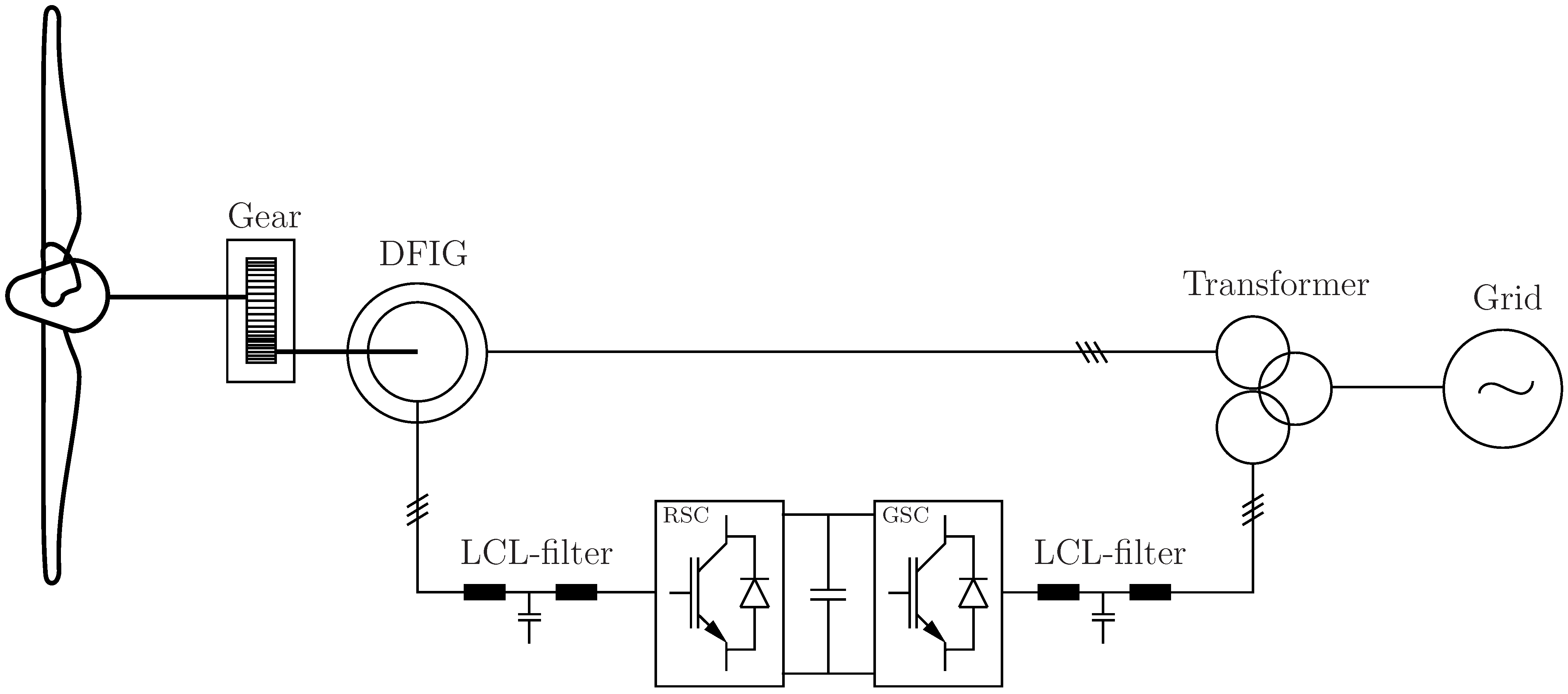
However, for wind energy plants equipped with a doubly fed induction generator (DFIG) and a power converter controlling the rotor circuit, no comparable grid forming control has been established. Due to the partial power rating of the inverter supplying the rotor circuit of the generator only, the DFIG concept is still widely employed, especially in the power range below [6]. In Figure 1, the power conversion and grid connection structure of a DFIG-based wind turbine is shown.
While the stator of the induction generator is directly connected to the electrical grid, the rotor side converter (RSC) operates the rotor circuit with only a fraction of the generated power transmitted through the converted depending on the machine slip.
The classical control schemes for the RSC have been derived from the established schemes used for adjustable motor drives. Typically, they are current controlled [7], where the set-points of the current controllers are derived from the references for active/reactive power, torque or voltage magnitudes [8,9]. The current control is usually done in a rotating reference frame. The reference frame is either voltage- or flux-oriented, which means that the d-axis of the reference frame is oriented along the stator voltage or flux (stator or rotor). Current control is also possible in the stationary reference frame using proportional resonant controllers, with a high or infinite gain at grid frequency [10,11,12]. The current control approach has the persuasive advantage of easy inverter protection by limiting the set-point values of the controllers but relies on an existing electrical grid that forms the connection point of the wind energy system.
To enable a stand-alone operation, i.e., autonomously supplying electrical loads, some concepts have been proposed to control the voltage at the generator terminal at a fixed frequency [13,14,15,16]. These concepts rely on a cascaded structure where an outer voltage control loop supplies the set-point for an inner rotor current control loop using the RSC. Instead of controlling the voltage directly [17], in [13,16], it has been proposed to control the stator flux to achieve the stand-alone operation. Using the stator flux linkages has the advantage that they are directly connected to the power of the machine, so these state variables are much less volatile compared to the stator voltage, for instance. In stationary operation, the stator flux linkages and the voltage magnitude are directly connected by the frequency if the voltage drop across the stator resistance is neglected.
In order to increase the grid support capabilities, in [18], it was proposed to adopt the rotor current set-points depending on the grid frequency and voltage magnitude after detecting an islanding event by means of corresponding droops. During the islanding events, significant oscillations have been observed. A similar structure has been proposed in [19] for stand-alone operation. In [20], the influence of different orientation systems on stability in low-voltage grids have been compared, but no results concerning transients, load changes or islanding events have been presented.
The main contribution of this paper is to extend the stator flux control of the DFIG by the droop control mechanisms known from full-power-rated inverter solutions. The aim is to operate the DFIG in a grid-forming mode, where the same control structure is used for grid-tied, stand-alone or islanded operation. In the case of an islanded grid involving the parallel operation of several generating units, the droop-based approach is inherently capable of performing power sharing according to the implemented droops.
The paper focuses on the grid forming nature of the proposed stator flux control and thereby does not cover any low-voltage ride through scenarios. Since the inner current control loop, however, is based on classical approaches, the well-established solutions [21,22] can be integrated into the control scheme, making the DFIG capable of low-voltage ride through. In addition, this paper does not cover the aspects of turbine control.
The paper is structured as follows: First, the stator flux control is described, and the extension using the frequency and voltage magnitude droops is discussed. Second, experimental results obtained from a laboratory setup are presented, which illustrate the operational properties using the proposed control scheme. Simulation results of a more complex three-node system follow. The article ends with a discussion and conclusion.
2. Stator Flux Control
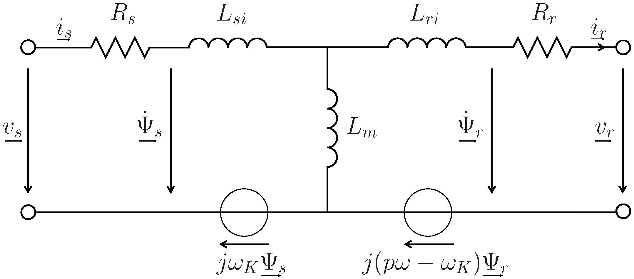
The equivalent space vector circuit diagram in an arbitrary reference frame rotating at the angular frequency is shown in Figure 2.
The stator flux of the machine can be calculated using the stator and rotor current [23]
where and are the stator and magnetizing inductances, respectively. This formulation, however, has the disadvantage that the flux depends on the inductances that vary significantly at different operating points due to the iron saturation. To avoid this dependency, the stator flux can be alternatively calculated by the integration of the stator voltage over time
On the other hand, the integration method is sensitive against even minor offset errors in stator voltage and current. Stabilizing the voltage integration by the low-pass filtered flux calculated from the currents will again result in strong dependency on the non-linear inductances. Therefore, we propose approximating the integration itself by a low-pass filter with a low cut-off frequency compared to the grid frequency [24]. For frequencies far beyond the cut off frequency, the low-pass filtering results in a phase shift of the output signal of nearly . The resulting amplitude and phase error of the low-pass filter approximation with respect to the ideal integrator at grid frequency is compensated by a subsequent vector rotation established by the exponential in Equation (3). Usually, the voltage drop across the stator resistance can safely be neglected as they are in a range of . As a result, the transfer function of the implemented open-loop flux estimator is given by
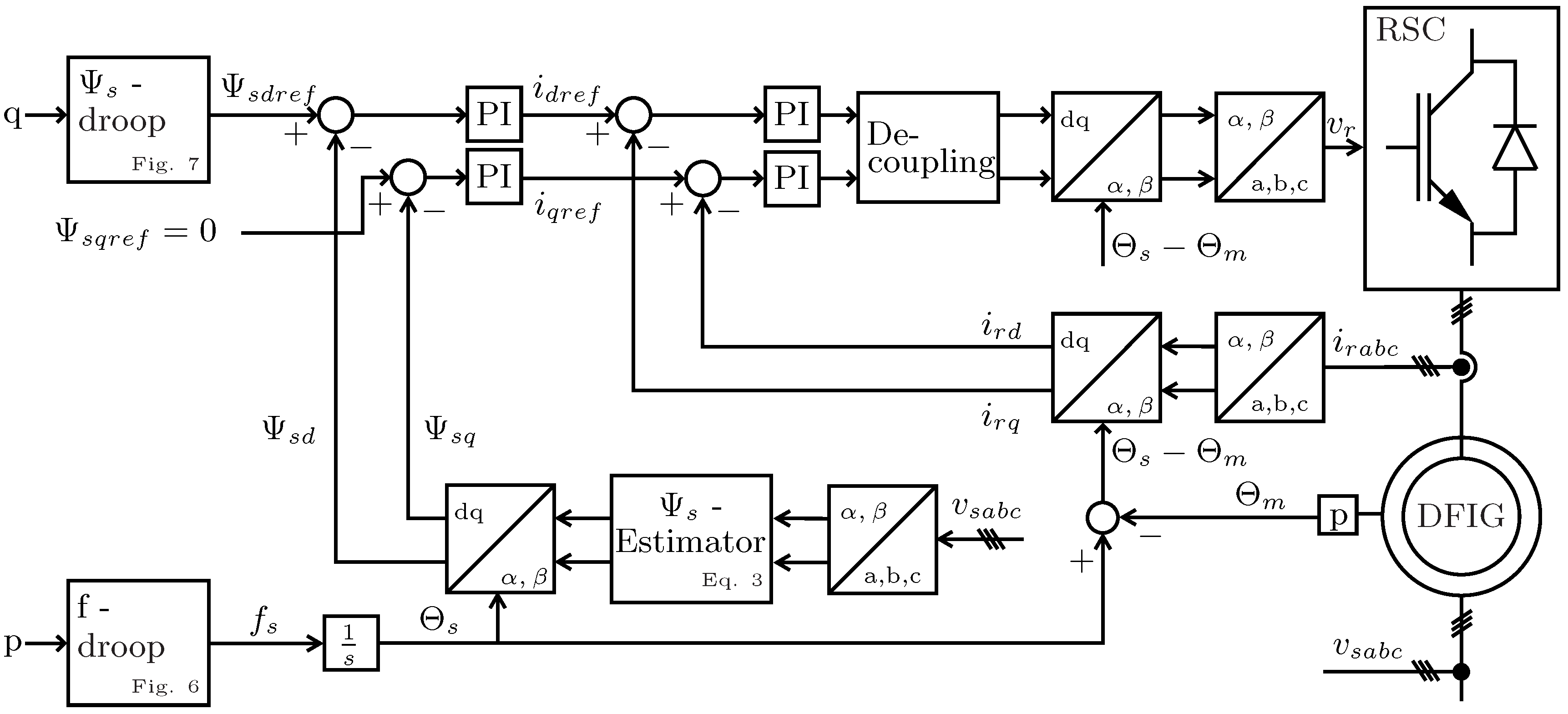
which is independent of any machine parameters. The aim of the proposed DFIG control is to guide the stator flux space vector in the stationary reference frame on a circular trajectory with a given magnitude and rotational frequency, such that in stationary conditions, the generator acts like a three-phase voltage source. As shown in [16], the stator flux can be controlled by the rotor currents in a cascaded structure with an inner fast rotor current control loop and an outer slower stator flux control loop. The cross-coupling between the d- and q-components in the inner rotor current control loop are reduced by introducing the corresponding feedforward terms for the induced voltages. The resulting control structure is shown in Figure 3.
During the design of the PI-control parameters of the rotor current controller,
the LCL-filter between the RSC and the rotor has to be taken into account. The reset time, , of the controller has been set to compensate for the open stator time constant of the plant while neglecting the filter capacitance of the filter. To avoid excitation of the filter resonance, the proportional gain is set such that the cut-off frequency of the rotor control loop is 10x lower than the resonant frequency of the LCL-filter.
2.1. Control of Frequency and Magnitude
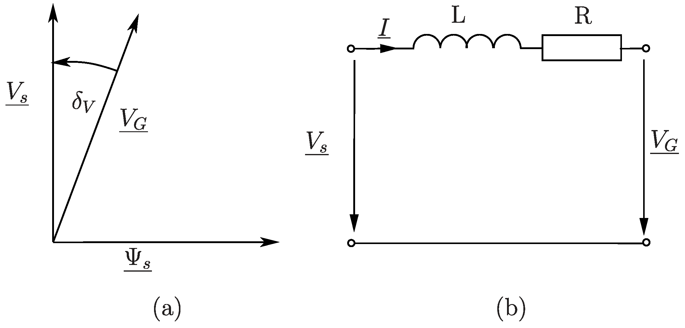
In quasi-stationary operation and neglecting the voltage drop at the stator resistance, the stator flux control results in a fixed stator voltage magnitude, . The simplified equivalent circuit shown in Figure 4 applies for the connection of the DFIG to the grid with the appropriate phasor diagram. The resulting impedance seen from the stator side mainly consists of the short circuit impedance of the feeding transformer in addition to the stator resistance and line filter. Other impedances usually have negligible effects on grid stability.
The active and reactive power components flowing to the grid depend mainly on the voltage amplitudes on both sides, the voltage angle between inverter and grid voltage and the resulting longitudinal impedance. Typically, the voltage angle is small so that the approximations and cos can be applied. In addition, the resistive component of the resulting filter impedance is small compared to the inductive component. As a result, using per unit quantities, the power relations are given by
where p and q represent the active and reactive power in per unit, respectively; represents the relative s/c voltage drop of the filter impedance; and denote the magnitude of stator and line voltage in per unit, respectively; represents the per unit stator flux magnitude; represent the angle between stator and line voltage phasors. These equations form the basics of grid control on a transmission level with high X/R values, where the active power p mainly depends on the voltage angle , and the reactive power q is mainly determined by the voltage amplitude difference and thus on the magnitude of stator flux. Both equations are well decoupled as long as the resistive component of the resulting impedance can be neglected, which is usually the case for transmission lines with typically high X/R ratios.
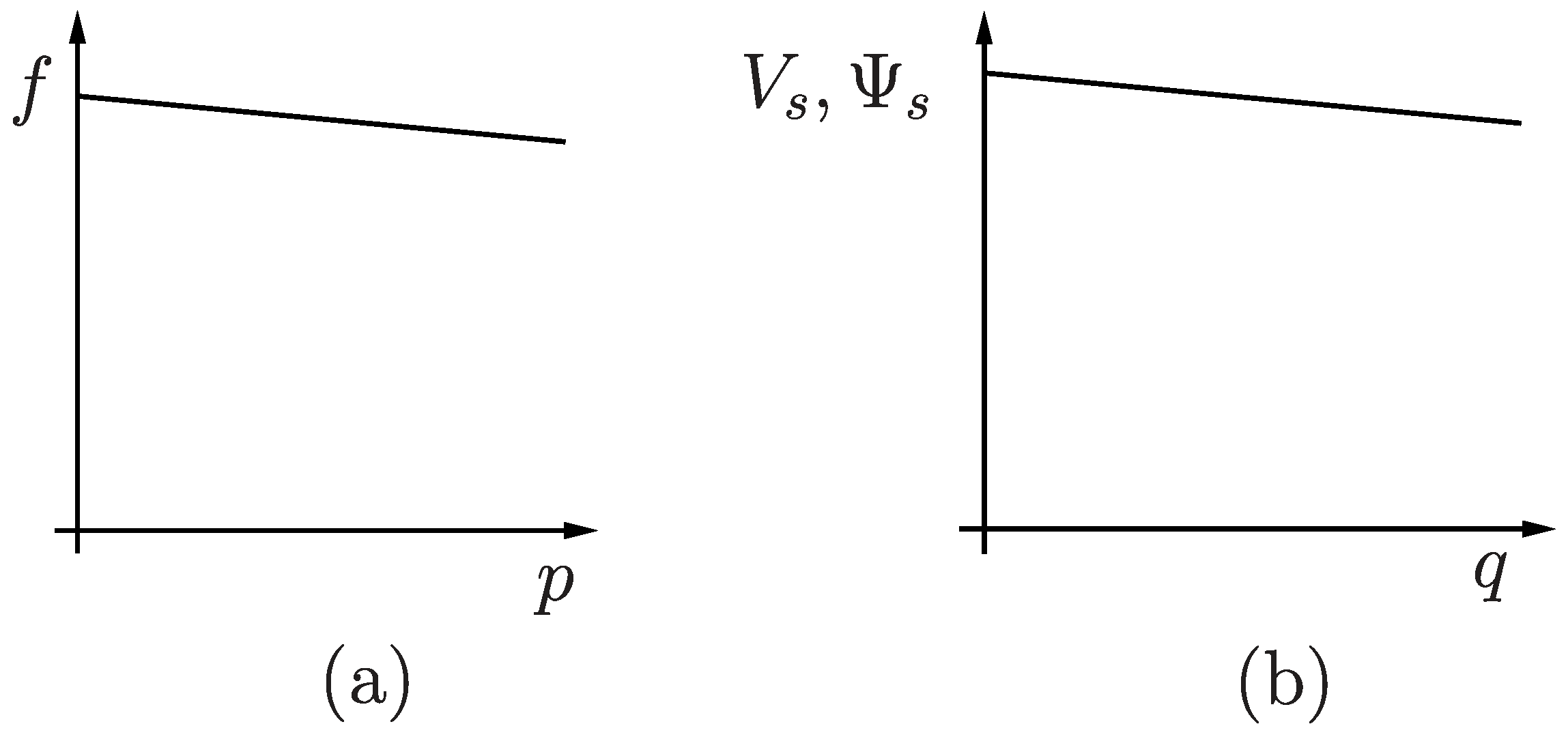
The primary control of conventional power plants with synchronous generators apply an active power dependent droop control for frequency and a voltage magnitude droop control depending on the reactive power. Depending on the type of power plant, the slope of the frequency droop is typically in the range of 2...6%, see Figure 5a.
This droop control of frequency causes good load sharing according to their p-f-curve and ensures inherent synchronism of the generators. Each power plant delivers the amount of active power according to its individual p-f-curve at the stationary condition. Using proper filter elements and tracking the p-f-curve by a secondary control, the dynamic behavior and load sharing can be controlled safely with regard to the specific type of power plant and the overall control objective.
In practice, a change in grid frequency greater than is only observed in very rare cases in the European grid. Thus, the corresponding power changes are usually less than 4% due to primary control. The aim is to maintain this grid’s stabilizing feature by controlling the DFIG accordingly. The droop control generates set-point values for frequency and stator flux amplitude. Under some conditions, this implementation can be shown to provide a similar dynamic behavior to a virtual synchronous machine [25]. The goal is not to reproduce the synchronous generator in all details but to extract its essential properties for grid stability.
2.1.1. Frequency Control
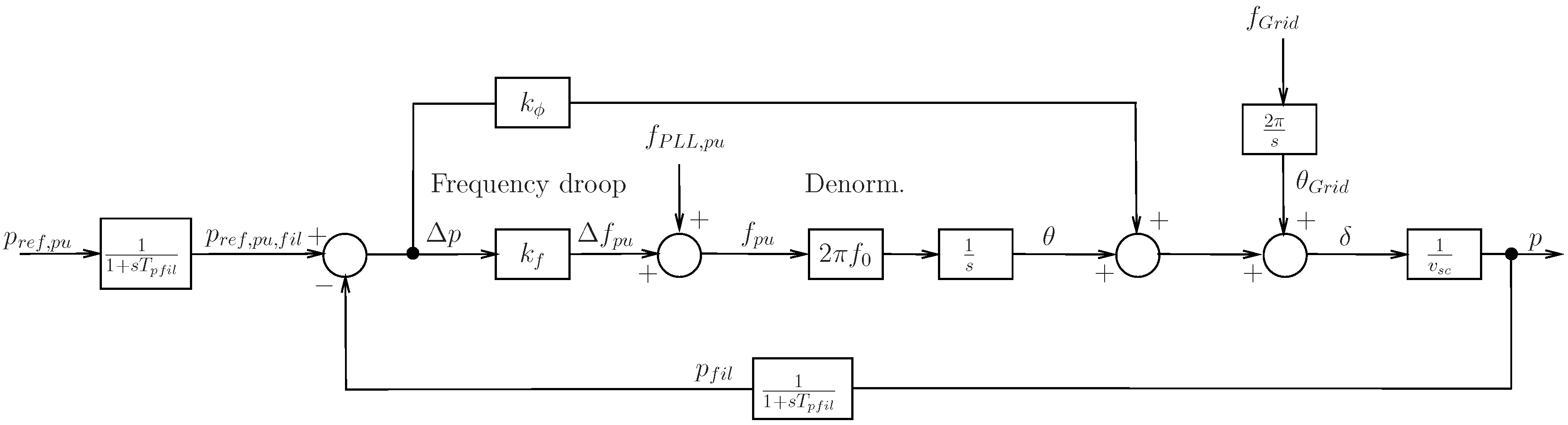
In [5,26,27], it has been proposed to extend the basic concept of frequency droop control by an additional phase intervention, which feeds the power error directly onto the voltage phase angle, see Figure 6. In principle, this corresponds to a differential intervention of the active power error to the frequency. The analytical gains design for this structure has been discussed in [28]:
where the closed loop transfer function results in
The additional feedforward path onto the voltage phase enables excellent damping, independent of the selected active power filter time constant. Thus, the slope of the frequency droop can be set similarly to those in conventional power plants maintaining a well-damped system response. Using this design, the response time is typically very fast, much less than . By means of an additional set-point filter, the desired overall time constant can be increased to a desired value with respect to the targeted frequency inertia.
2.1.2. Stator Flux Magnitude Control
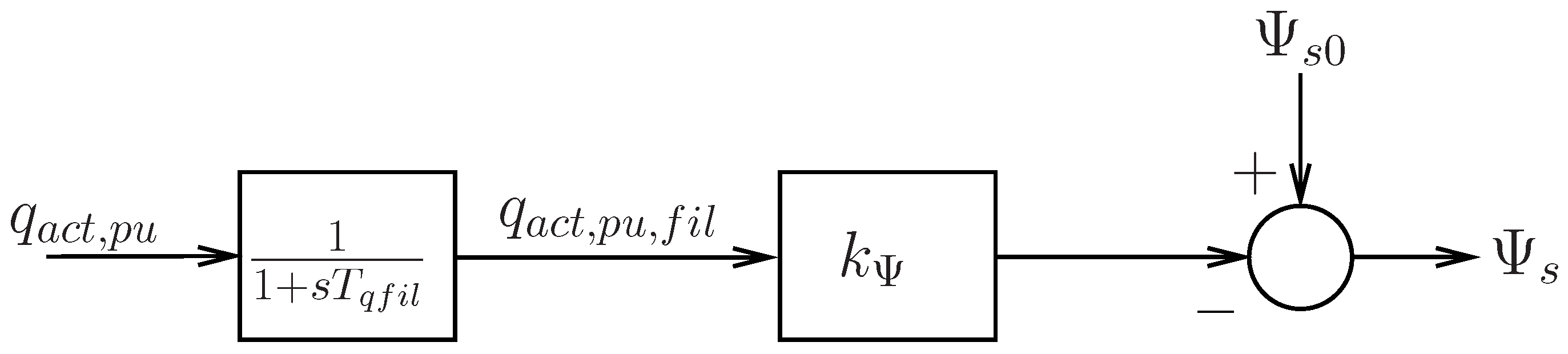
According to Equation (5), the difference in voltage magnitudes of the stator and grid is proportional to the reactive power. In order to stabilize the grid voltage to a desired value, the amount of reactive power will be set as a function of the grid voltage, see Figure 5b. Instead of directly controlling the stator voltage magnitude, the desired stator flux magnitude can be adjusted accordingly. At constant frequency, the stator flux control will also yield a constant voltage magnitude neglecting the typically small voltage drop at the stator resistance. The stator flux amplitude is adjusted depending on the reactive power supplied to the grid, see Figure 7.
Thus, operating the DFIG like a voltage source or synchronous generator with adjustable frequency, phase and amplitude, the generator inherently gives ancillary grid services, such as frequency and voltage support. On a grid frequency change, the generator will immediately respond with a corresponding change in active power, and on a voltage sag, the generator will immediately increase the reactive power. In addition, it ensures adequate sharing of active and reactive power among multiple feeding power plants. These important properties are to be maintained by modern control strategies for DFIG in order to ensure grid stability with the future increase in renewable energy sources.
3. Experimental Validation of the Control Scheme
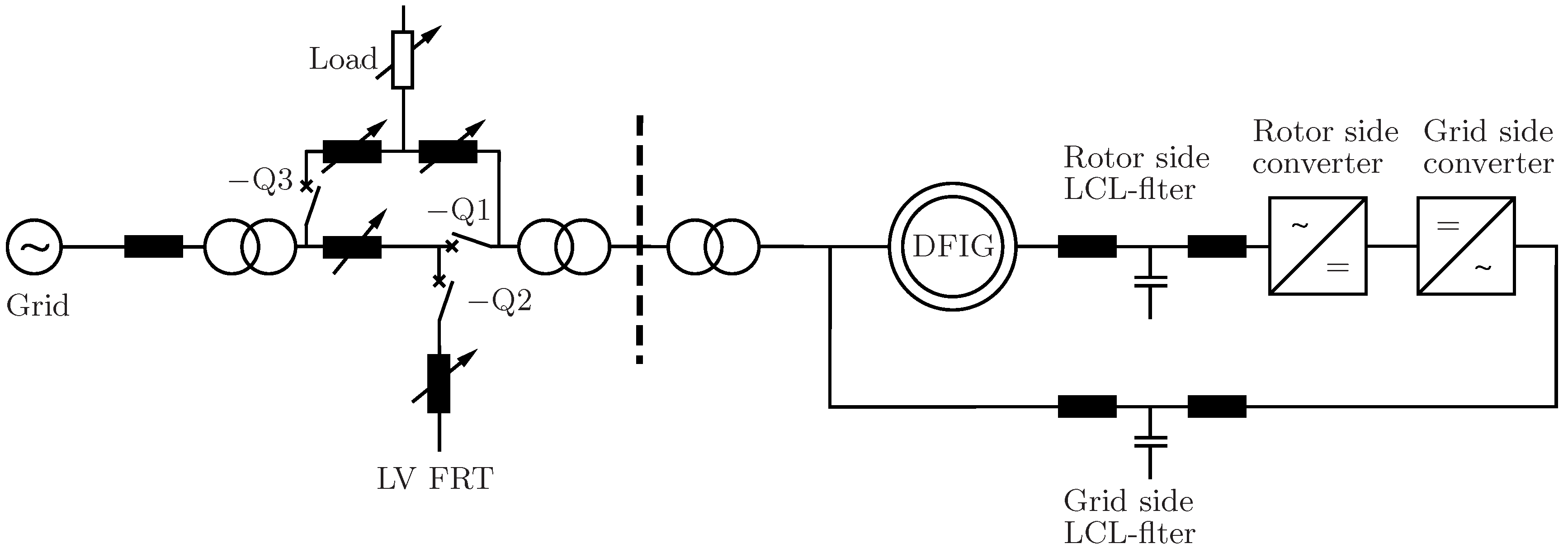
The test bench, see Figure 8, consists of a back-to-back inverter with corresponding LCL-filters, a grid representation and a fault branch [29]. The impedances of the grid and the fault branch can be changed in a wide range. With the help of contactors Q1... Q3, an islanding event and dynamic changes of transmission impedances can be realized. The parameters of the test bench have been chosen as to emulate a real wind power plant with typical pu values for filter and grid impedances, switching frequency and filter resonance frequencies of LCL-filters. Since low-power transformers usually have lower X/R values than high-power transformers, transformers with a low short-circuit impedance have been used, which have been artificially increased by external chokes with low-resistive components.
The controller for the back-to-back inverter uses a dual core signal controller of the type TMS320F28379D from Texas Instruments. The RSC is controlled by one core, the GSC by the other one, and data exchange is done via on-chip shared memory. The control algorithm of the RSC is set up in accordance to the structures shown in Figure 3, Figure 6 and Figure 7. The software of the main control functions was generated by the code generation tool from the simulation structure. The functions and tasks for inverter protection, pulse width modulation, A/D conversion, communication and state machine were developed separately. The system parameters are summarized in Table 1.
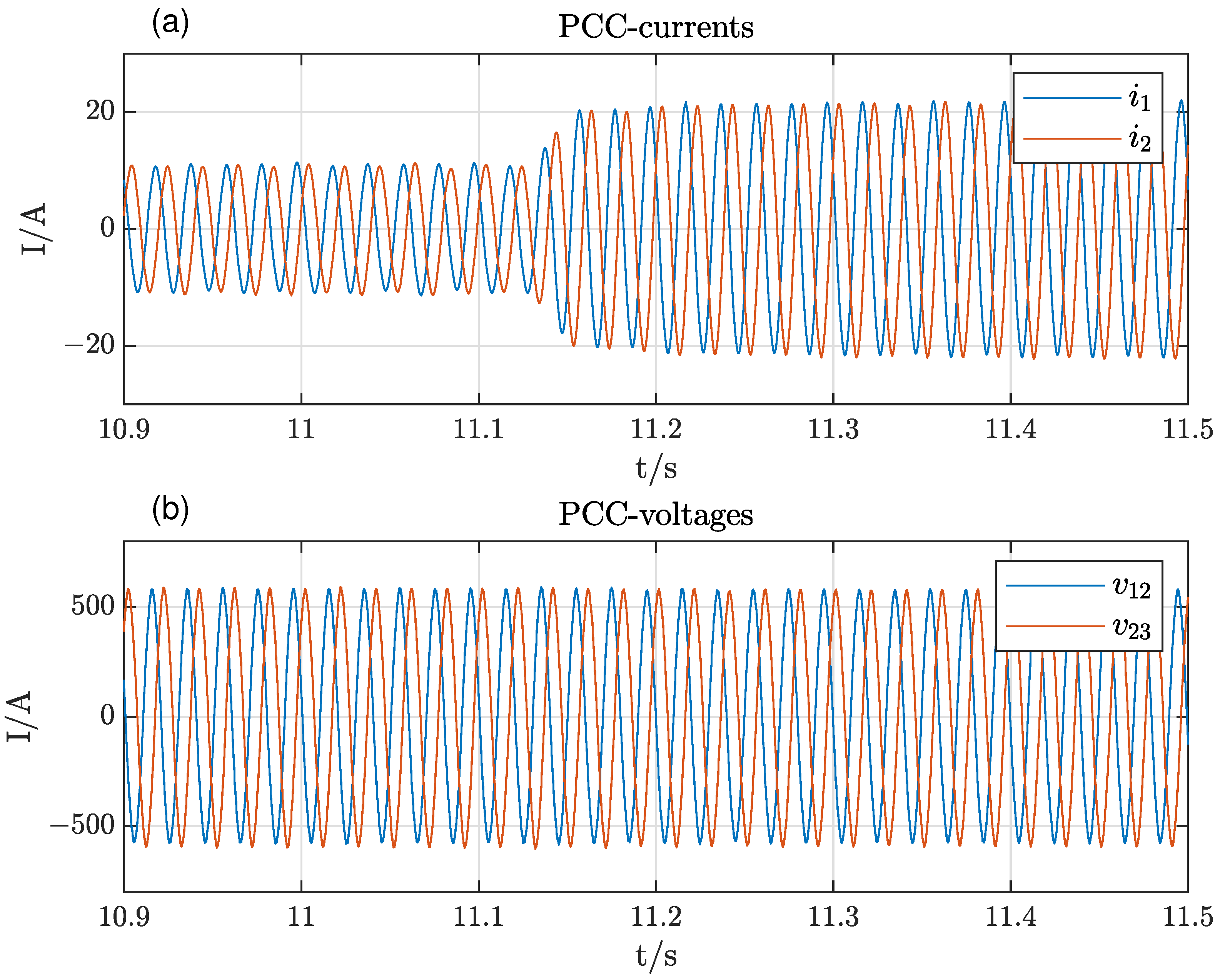
In grid-tied operation, the excellent behavior of the control scheme could be verified. Figure 9 shows the voltages and currents at the point of common coupling (PCC) when the active power set-point changes from 50% to 100%. The rise time is about 20 ms, and the response is well damped.
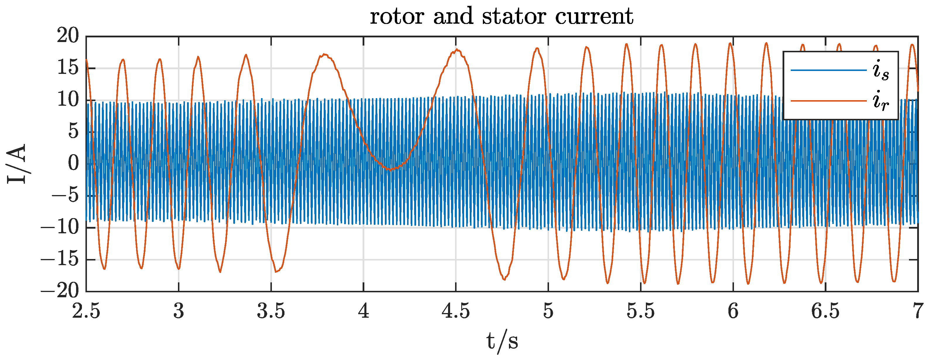
The ability to operate at varying rotor speeds and, thereby, slips is shown in Figure 10. The mechanical speed has been changed from 10% supersynchronous speed to 10% subsynchronous speed within . Stator and rotor currents do not show any disruptive transients during these significant speed changes.
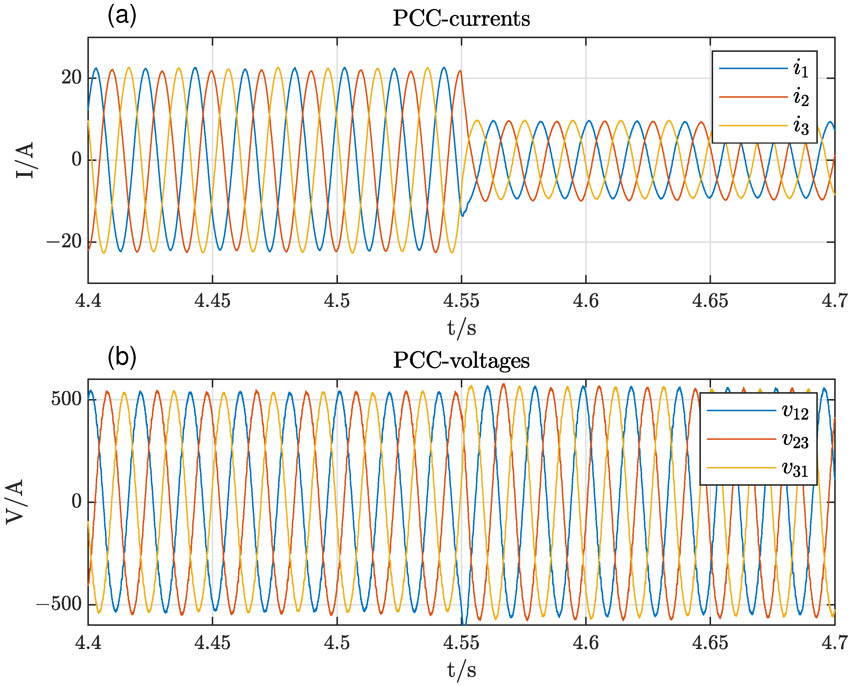
The advantage of the proposed stator flux control is evident, especially after an islanding event. In Figure 11, the DFIG is first connected to the grid with full power. At , the DFIG is disconnected from the grid and feeds a residual load of only 40%. There are no significant transients, and the voltage at the PCC slightly rises due to the reduced voltage drop across the line filter, see Figure 11b. The frequency is not constant anymore in islanded operation but varies slightly according to the implemented frequency droop.
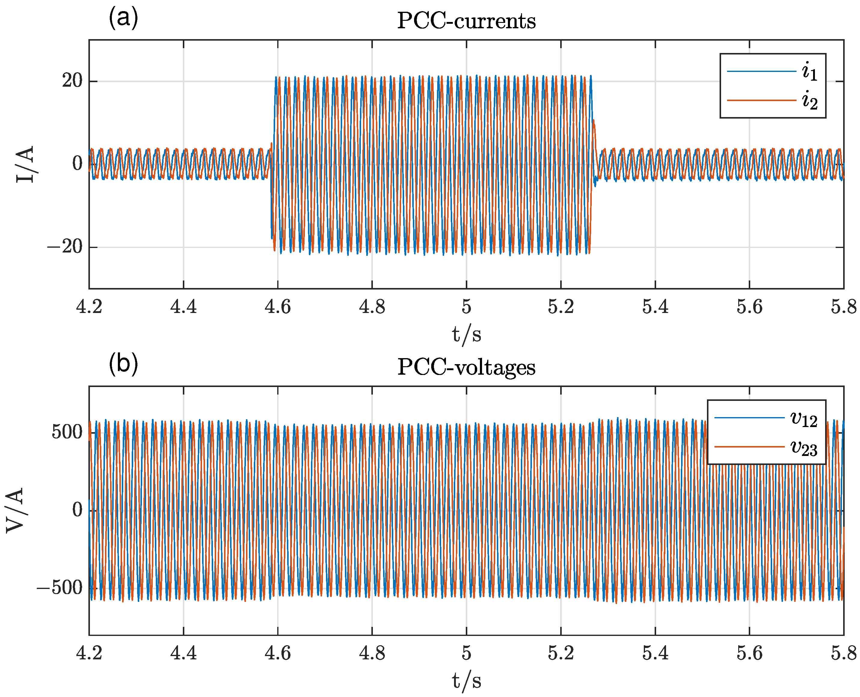
The system behavior at load changes in islanded mode is presented in Figure 12. The load has been changed from 20% to 100% and back within about . During the full-load period, the voltage drops again slightly, but otherwise, no disruptive transients occurred.
4. Simulation of 3-Node Grid
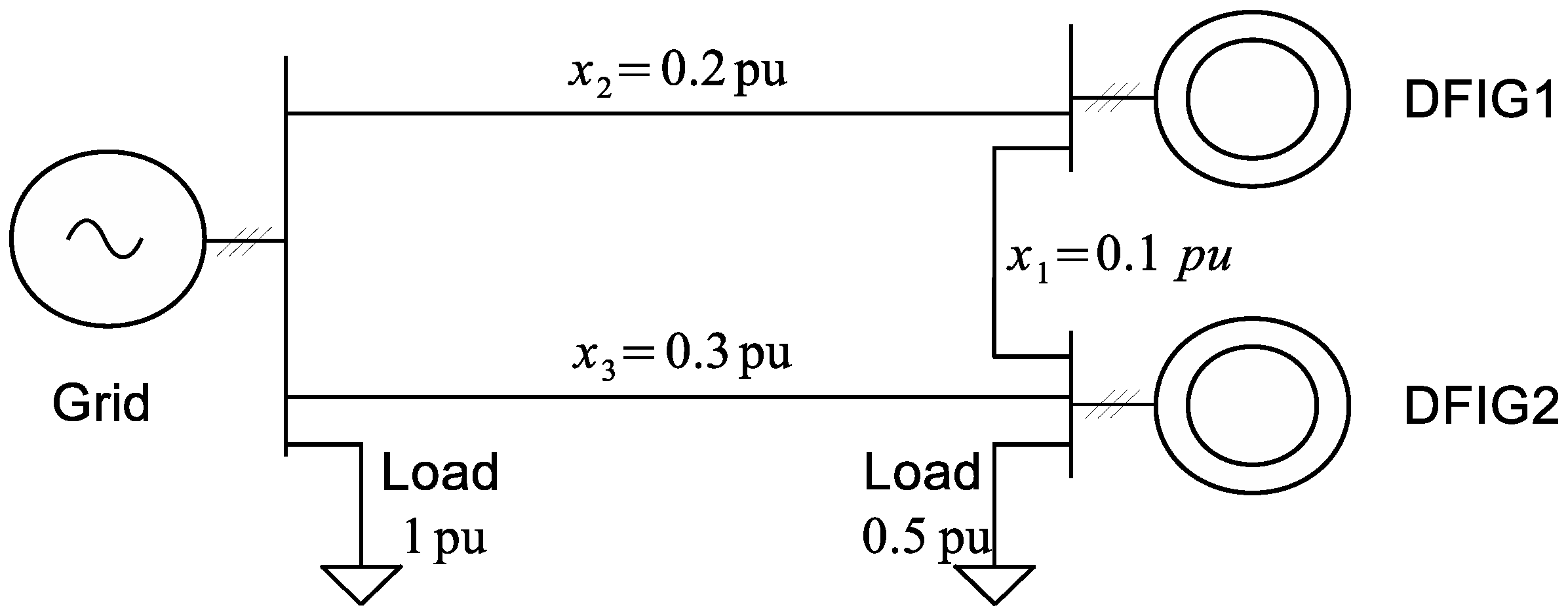
To evaluate the performance of the proposed control system in a more complex environment, a system consisting of a 3-node grid, see Figure 13, has been modeled in Simulink®.
The 3-node grid consists of a grid connection on one node and two DFIGs on the other nodes. Both DFIGs are equally rated and parameterized, but the line impedances between the node are different. The transmission line impedance between the two DFIGs is , and the transmission line impedances between the DFIG1/DFIG2 and the grid are and , respectively. A load with is connected to the grid and a load of is connected to the DFIG2, while DFIG1 has no load connected directly. The simulation is carried out as a full EMT simulation, and the result is shown in Figure 14.
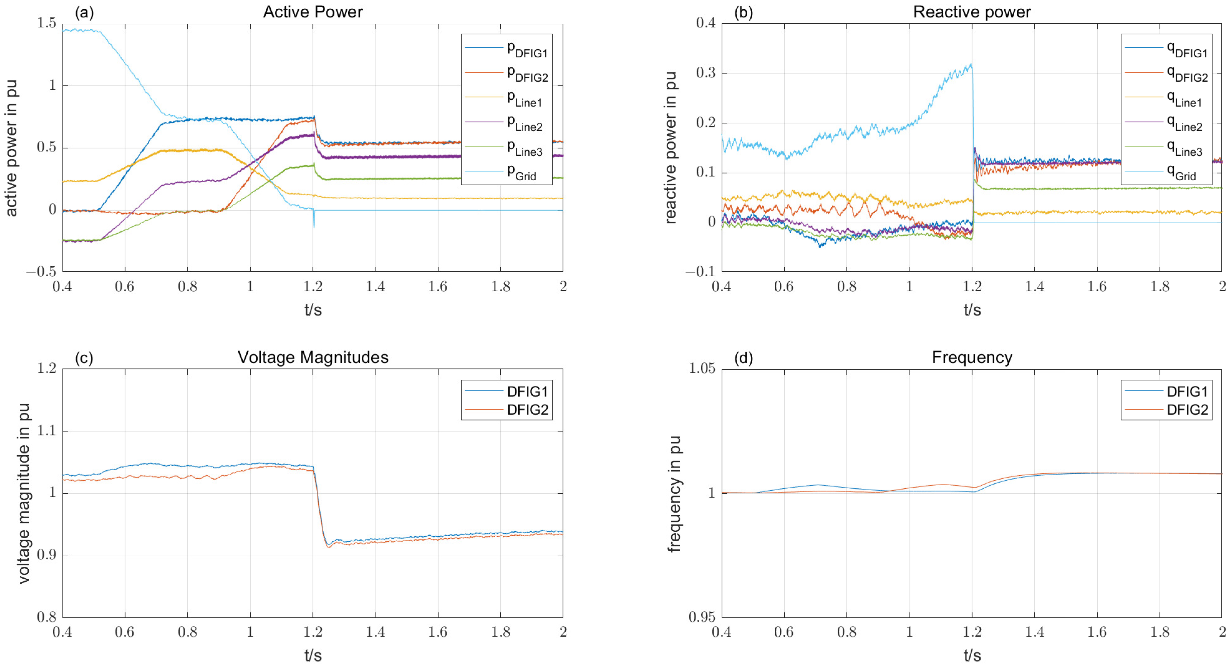
When the simulation commences, both DFIGs are in idle mode, i.e., all the power for both the loads is supplied by the grid. At , the reference power for DFIG1 is ramped up to within . The power drawn from the grid reduces accordingly. The voltage at DFIG1 is increased due to the flux droop. During the rise time of active power, the frequency is increased slightly in order to build up the proper voltage angle and decays back to the grid frequency. At , the power reference of DFIG2 is ramped up to . As a result, the active power drawn from the grid decays to almost zero. At , the grid is disconnected from the node, and the DFIGs supply the residual grid consisting of three transmission lines and two loads alone. From now on, the frequency is no more fixed, and both rise according to their p-f curves. The node voltages decrease after islanding because of missing reactive power from the grid. After islanding, the DFIGs show effective active and reactive power sharing despite significant asymmetries in the network transmission lines. The simulation has proven that the proposed stator flux control is well suited for grid-tied operation as well as for islanding events or island operation.
5. Conclusions and Future Work
It has been shown that wind energy plants equipped with doubly fed induction generators can achieve excellent grid forming and grid supporting behavior using stator flux control with droops for frequency and magnitude. The main control scheme is applicable for grid-tied operation as well as for islanded operation. In many aspects, the system behaves like a conventional power plant. The experimental validation has confirmed the concept. The achieved system dynamics are satisfactory and show no disruptive transients. Future work will cover the integration with other producers into a dynamic virtual power plant (DVPP) as well as the system response to symmetrical and asymmetrical grid faults.
Author Contributions
Conceptualization, investigation, data curation and writing—review and editing, N.K.; formal analysis, writing original draft, preparation, methodology, validation, N.K., F.P. and H.S.; supervision, project administration, N.K. and H.S.; funding acquisition, H.S. All authors have read and agreed to the published version of the manuscript.
Funding
This research was funded by the European Union’s Horizon 2020 research and innovation program under grant agreement No. 883985 (POSYTYF—POwering SYstem flexibiliTY in the Future through RES).
Conflicts of Interest
The authors declare no conflict of interest. The funders had no role in the design of the study; in the collection, analyses, or interpretation of data; in the writing of the manuscript, or in the decision to publish the results.
References
- Hansen, A.D.; Hansen, L.H. Wind turbine concept market penetration over 10 years (1995–2004). Wind Energy 2007, 10, 81–97. [Google Scholar] [CrossRef]
- De Brabandere, K.; Bolsens, B.; Van den Keybus, J.; Woyte, A.; Driesen, J.; Belmans, R. A Voltage and Frequency Droop Control Method for Parallel Inverters. IEEE Trans. Power Electron. 2007, 22, 1107–1115. [Google Scholar] [CrossRef]
- Lopes, J.A.P.; Moreira, C.L.; Madureira, A.G. Defining control strategies for MicroGrids islanded operation. IEEE Trans. Power Syst. 2006, 21, 916–924. [Google Scholar] [CrossRef] [Green Version]
- Yao, W.; Chen, M.; Matas, J.; Guerrero, J.M.; Qian, Z. Design and Analysis of the Droop Control Method for Parallel Inverters Considering the Impact of the Complex Impedance on the Power Sharing. IEEE Trans. Ind. Electron. 2011, 58, 576–588. [Google Scholar] [CrossRef]
- Engler, A.; Soultanis, N. Droop control in LV-grids. In Proceedings of the 2005 International Conference on Future Power Systems, Amsterdam, The Netherlands, 18 November 2005. [Google Scholar]
- Vazquez Hernandez, C.; Telsnig, T.; Villalba Pradas, A. JRC Wind Energy Status Report: 2016 Edition; Technical Report; Publications Office of the European Union: Luxembourg, 2017. [CrossRef]
- Blaabjerg, F.; Teodorescu, R.; Liserre, M.; Timbus, A.V. Overview of Control and Grid Synchronization for Distributed Power Generation Systems. IEEE Trans. Ind. Electron. 2006, 53, 1398–1409. [Google Scholar] [CrossRef] [Green Version]
- Cortajarena, J.A.; De Marcos, J.; Alkorta, P.; Barambones, O.; Cortajarena, J. DFIG wind turbine grid connected for frequency and amplitude control in a smart grid. In Proceedings of the 2018 IEEE International Conference on Industrial Electronics for Sustainable Energy Systems (IESES), Hamilton, New Zealand, 31 January–2 February 2018; pp. 362–369. [Google Scholar] [CrossRef]
- Cortajarena, J.A.; Barambones, O.; Alkorta, P.; Cortajarena, J. Grid Frequency and Amplitude Control Using DFIG Wind Turbines in a Smart Grid. Mathematics 2021, 9, 143. [Google Scholar] [CrossRef]
- Yan, Y.; Wang, M.; Song, Z.F.; Xia, C.L. Proportional-Resonant Control of Doubly-Fed Induction Generator Wind Turbines for Low-Voltage Ride-Through Enhancement. Energies 2012, 5, 4758–4778. [Google Scholar] [CrossRef] [Green Version]
- Busada, C.A.; Jorge, S.G.; Solsona, J.A. Resonant Current Controller With Enhanced Transient Response for Grid-Tied Inverters. IEEE Trans. Ind. Electron. 2018, 65, 2935–2944. [Google Scholar] [CrossRef]
- Schiesser, M.; Wasterlain, S.; Marchesoni, M.; Carpita, M. A Simplified Design Strategy for Multi-Resonant Current Control of a Grid-Connected Voltage Source Inverter with an LCL Filter. Energies 2018, 11, 609. [Google Scholar] [CrossRef] [Green Version]
- Pena, R.; Clare, J.C.; Asher, G.M. A doubly fed induction generator using back-to-back PWM converters supplying an isolated load from a variable speed wind turbine. IEE Proc. Electr. Power Appl. 1996, 143, 380–387. [Google Scholar] [CrossRef]
- Shukla, R.D.; Tripathi, R.K. A novel voltage and frequency controller for standalone DFIG based Wind Energy Conversion System. Renew. Sustain. Energy Rev. 2014, 37, 69–89. [Google Scholar] [CrossRef]
- Ataji, A.B.; Miura, Y.; Ise, T.; Tanaka, H. Direct Voltage Control With Slip Angle Estimation to Extend the Range of Supported Asymmetric Loads for Stand-Alone DFIG. IEEE Trans. Power Electron. 2016, 31, 1015–1025. [Google Scholar] [CrossRef]
- Arnaltes, S.; Rodriguez-Amenedo, J.L.; Montilla-DJesus, M.E. Control of Variable Speed Wind Turbines with Doubly Fed Asynchronous Generators for Stand-Alone Applications. Energies 2018, 11, 26. [Google Scholar] [CrossRef] [Green Version]
- Fazeli, M.; Asher, G.M.; Klumpner, C.; Yao, L. Novel Integration of DFIG-Based Wind Generators Within Microgrids. IEEE Trans. Energy Convers. 2011, 26, 840–850. [Google Scholar] [CrossRef]
- Shahabi, M.; Haghifam, M.R.; Mohamadian, M.; Nabavi-Niaki, S.A. Microgrid Dynamic Performance Improvement Using a Doubly Fed Induction Wind Generator. IEEE Trans. Energy Convers. 2009, 24, 137–145. [Google Scholar] [CrossRef]
- Zhang, Y.; Ooi, B. DFIG based wind farm with autonomous frequency control on island operation. In Proceedings of the 2015 IEEE Power and Energy Society General Meeting, Denver, CO, USA, 26–30 July 2015; pp. 1–5. [Google Scholar] [CrossRef]
- Han, Y.; Ha, J.I. Droop Control Using Impedance of Grid-Integrated DFIG within Microgrid. IEEE Trans. Energy Convers. 2019, 34, 88–97. [Google Scholar] [CrossRef]
- Yang, J.; Dorrell, D.G.; Fletcher, J.E. Fault ride-through of doubly-fed induction generator with converter protection schemes. In Proceedings of the 2008 IEEE International Conference on Sustainable Energy Technologies, Singapore, 24–27 November 2008; pp. 1211–1216. [Google Scholar] [CrossRef] [Green Version]
- Naderi, S.B.; Davari, P.; Zhou, D.; Negnevitsky, M.; Blaabjerg, F. A Review on Fault Current Limiting Devices to Enhance the Fault Ride-Through Capability of the Doubly-Fed Induction Generator Based Wind Turbine. Appl. Sci. 2018, 8, 2059. [Google Scholar] [CrossRef] [Green Version]
- Fletcher, J.; Yang, J. Introduction to the Doubly-Fed Induction Generator for Wind Power Applications; Intech Open: London, UK, 2010. [Google Scholar] [CrossRef] [Green Version]
- Kadri, A.; Marzougui, H.; Bacha, F. Implementation of direct power control based on stator flux estimation using low-pass filter estimator for doubly fed induction generator-wind energy conversion system. Proc. Inst. Mech. Eng. Part I J. Syst. Control Eng. 2019, 233, 764–778. [Google Scholar] [CrossRef]
- D’Arco, S.; Suul, J.A. Equivalence of Virtual Synchronous Machines and Frequency-Droops for Converter-Based MicroGrids. IEEE Trans. Smart Grid 2014, 5, 394–395. [Google Scholar] [CrossRef]
- Engler, A. Device for Equal-Rated Parallel Operation of Single-Or Three-Phase Voltage Sources. U.S. Patent 6693809, 17 February 2004. [Google Scholar]
- Strauss, P.; Engler, A. AC coupled PV hybrid systems and microgrids-state of the art and future trends. In Proceedings of the 3rd World Conference on Photovoltaic Energy Conversion, Osaka, Japan, 11–18 May 2003; Volume 3, pp. 2129–2134. [Google Scholar]
- Klaes, N.; Goldschmidt, N.; Fortmann, J. Voltage Fed Control of Distributed Power Generation Inverters with Inherent Service to Grid Stability. Energies 2020, 13, 2579. [Google Scholar] [CrossRef]
- Kisser, A.; Engel, M.; Rezai, L.; Andrejewski, M.; Fortmann, J.; Schulte, H. A Test-bed System for Validation of Ancillary Services of Wind Power Plants under Realistic Conditions. In Proceedings of the 16th Int’l Wind Integration Workshop, Berlin, Germany, 25–27 October 2017. [Google Scholar]
Figure 1.
Main structure of electrical power conversion for DFIG-based power plants.

Figure 2.
Equivalent space vector circuit diagram of DFIG.

Figure 3.
Main control structure.

Figure 4.
(a) Equivalent circuit. (b) Phasor diagram.

Figure 5.
(a) Droop control of frequency. (b) Droop control of voltage or stator flux magnitude.

Figure 6.
Enhanced Frequency control with phase intervention.

Figure 7.
Adjustment of stator flux magnitude.

Figure 8.
Single line diagram of the test bench.

Figure 9.
Load step change in grid-tied condition: (a) PCC-currents and (b) PCC-voltages.

Figure 10.
Change from supersynchronous speed to subsynchromous speed.

Figure 11.
Islanding event at full power: (a) PCC-currents and (b) PCC-voltages.

Figure 12.
Load step change in grid-tied condition: (a) PCC currents and (b) PCC-voltages.

Figure 13.
Modeled 3-node grid with 2 DFIGs.

Figure 14.
Simulation results of grid-forming operation in a 3-node grid: (a) active power. (b) reactive power, (c) voltage magnitudes and (d) frequency.
Figure 14.
Simulation results of grid-forming operation in a 3-node grid: (a) active power. (b) reactive power, (c) voltage magnitudes and (d) frequency.


Table 1.
System Parameters.
| Symbol | Parameter | Value | Units |
|---|---|---|---|
| f | Grid frequency | 50 | Hz |
| Nominal apparent power | 10 | kVA | |
| Switching frequency | 1950 | Hz | |
| Filter time constant for active power | 100 | ms | |
| Filter time constant for reactive power | 100 | ms | |
| Frequency droop | 4% | ||
| Phase intervention gain | 0.4 | rad/pu | |
| Stator flux droop | 1 | ||
| Cut off frequency of flux estimator | 5 | Hz |
Publisher’s Note: MDPI stays neutral with regard to jurisdictional claims in published maps and institutional affiliations. |
© 2021 by the authors. Licensee MDPI, Basel, Switzerland. This article is an open access article distributed under the terms and conditions of the Creative Commons Attribution (CC BY) license (https://creativecommons.org/licenses/by/4.0/).
Share and Cite
MDPI and ACS Style
Klaes, N.; Pöschke, F.; Schulte, H. Grid Forming Stator Flux Control of Doubly-Fed Induction Generator. Energies 2021, 14, 6766. https://0-doi-org.brum.beds.ac.uk/10.3390/en14206766
AMA Style
Klaes N, Pöschke F, Schulte H. Grid Forming Stator Flux Control of Doubly-Fed Induction Generator. Energies. 2021; 14(20):6766. https://0-doi-org.brum.beds.ac.uk/10.3390/en14206766
Chicago/Turabian StyleKlaes, Norbert, Florian Pöschke, and Horst Schulte. 2021. "Grid Forming Stator Flux Control of Doubly-Fed Induction Generator" Energies 14, no. 20: 6766. https://0-doi-org.brum.beds.ac.uk/10.3390/en14206766
Note that from the first issue of 2016, this journal uses article numbers instead of page numbers. See further details here.