
Voltage Control of Multiphase Cage Induction Generators at a Speed Varying over a Wide Range


Faculty of Electrical and Computer Engineering, Cracow University of Technology, Warszawska 24 Str., 31-155 Cracow, Poland
*
Author to whom correspondence should be addressed.
Energies 2021, 14(21), 7080; https://0-doi-org.brum.beds.ac.uk/10.3390/en14217080
Submission received: 21 September 2021
/
Revised: 21 October 2021
/
Accepted: 21 October 2021
/
Published: 29 October 2021
(This article belongs to the Special Issue Control, Operation and Protection of Multiphase Machines and Drives)
Abstract
:The subject of this publication is a method of controlling the DC voltage of a PWM rectifier supplied by a multiphase cage induction generator with the number of stator phases greater than three operating in a wide range of driving speeds. Voltage regulation is performed by changing the frequency and amplitude of the stator voltages with simultaneous switching of the phase sequence of these voltages. The step change of the voltage sequence is made in the designated ranges of the generator speed, which enables the stabilization of the output voltage in a wide range from the minimum speed of about 25% of the rated speed. Such sequence switching changes the number of pole pairs produced by the winding for each supply sequence. The difference compared to multi-speed induction machines is that, in the presented solution, there is only one winding, not a few, which enables good use of the machine’s magnetic core in the same dimensions as for the three-phase machine of a similar power. Steady-state characteristics and dynamic operation were obtained using laboratory measurements of a standalone nine-phase induction generator. The automatic control system maintained the output voltage at the set level, regardless of the generator load and driving power.
1. Introduction
A multiphase induction machine (MIM) with number of phases can operate as a motor or a generator. The idea of MIM operation as a stator converter-controlled multiphase generator [1] was created on the basis of automatic speed control of the multiphase squirrel-cage induction motor presented in [2,3,4]. The motivation for the use of MIM as an induction generator stemmed from the properties of the machine during motor operation and regenerative braking presented in [2,3,4]. These were mainly the ability to work with broken stator phases and to work with a constant frequency and voltage at several different characteristic speeds. To achieve this, the supply sequence of the multiphase stator winding must be adapted at each of these speeds. Switching the supply sequence changes the number of pole pairs of the magnetic field. In the ranges between these speeds, MIM control is performed by scalar frequency and voltage control or by vector control. This is the basis for stabilizing the generator voltage when changing its speed over a wide range. The machine has one multiphase winding controlled by a multiphase converter. Details are explained below.
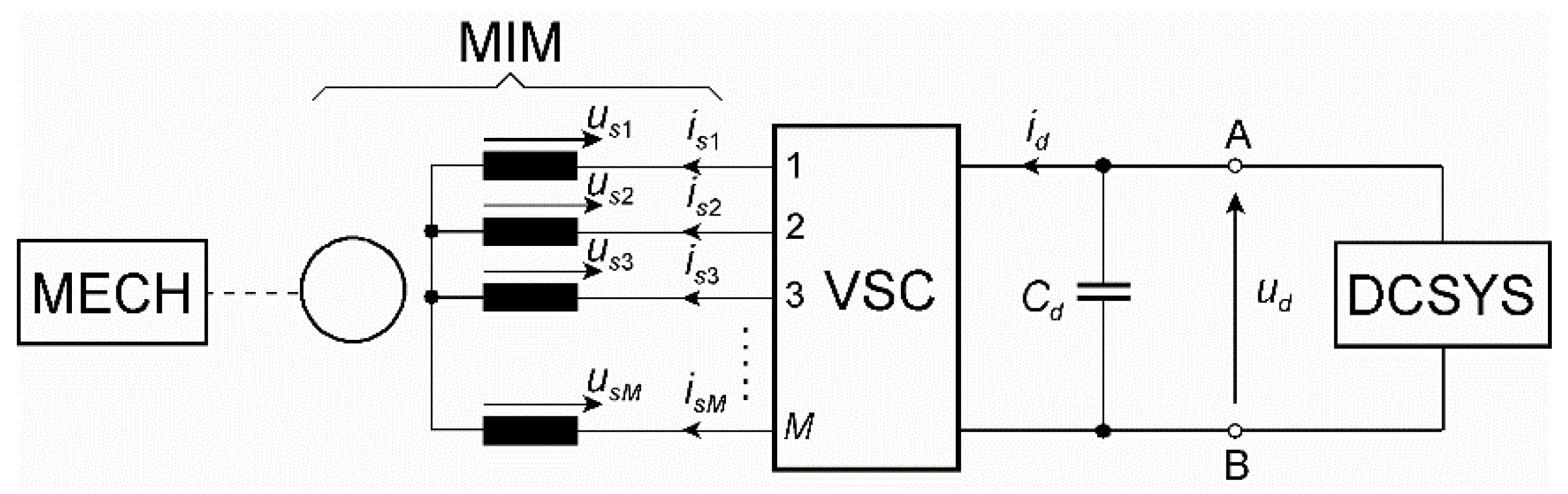
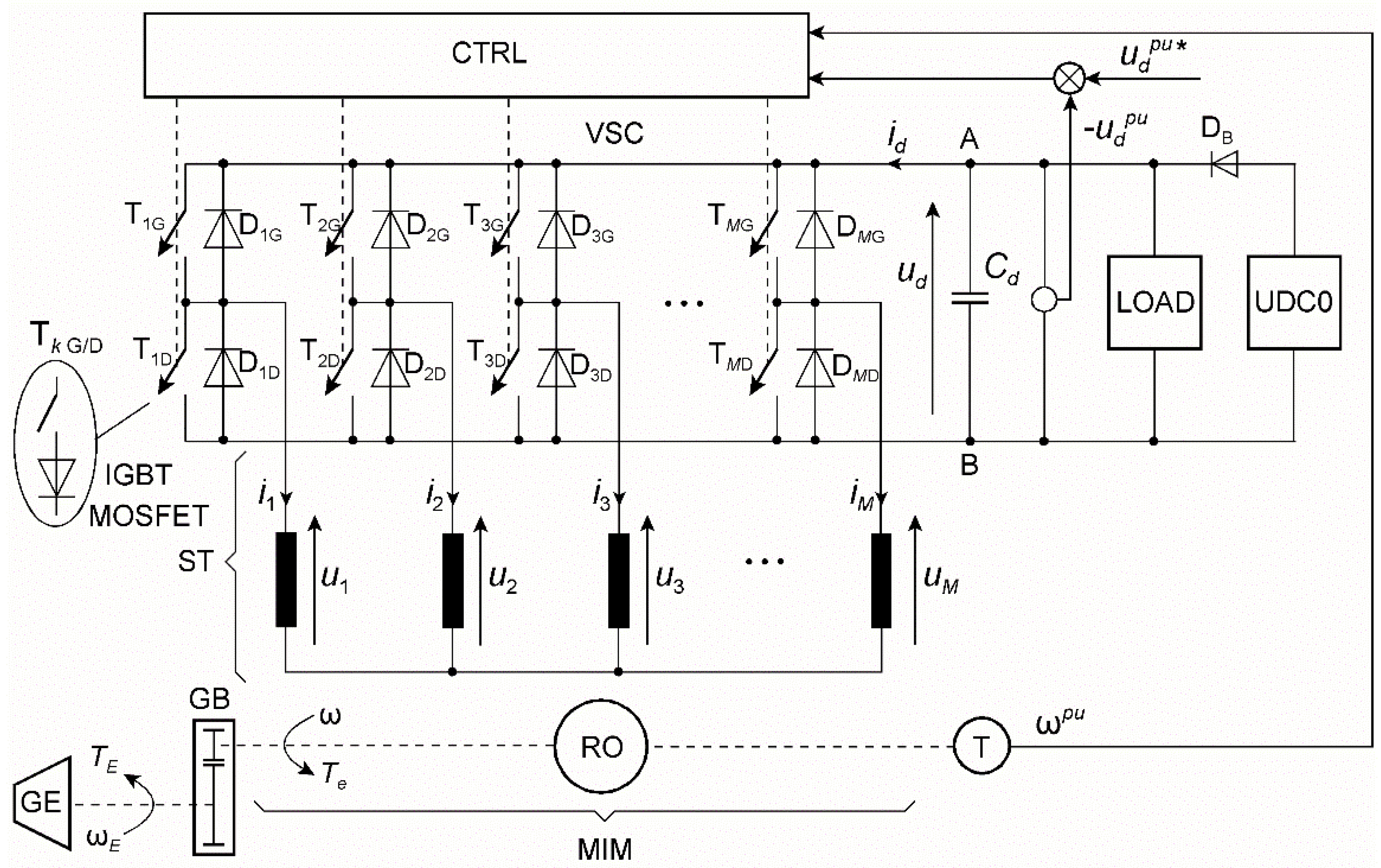
During motor operation, the MIM in Figure 1 is loaded with a mechanical system MECH and directly powered by a PWM-controlled voltage source converter (VSC) during inverter operation, fed from DCSYS.
In order to generate electricity, the drive must be controlled only for generator operation. Then, the MIM is powered from the rotor side by MECH with turbine torque and speed (e.g., wind or water energy). This allows building an automatic regulation system that stabilizes the voltage between A and B terminals regulating VSC as a PWM rectifier (machine side converter). This time, DCSYS is a loading system, e.g., PWM inverter (grid side converter), operating upon three-phase power system or a resistive load supplied by the auxiliary converter [1,5,6,7,8,9].
Using three-phase or multiphase induction machines as a generator, the minimum speed when the voltage can obtain the nominal (required) value should not be lower than about two-thirds of the nominal speed [5,6,10] taken for the rated frequency . For example, from [5,11], it follows that a doubly fed induction generator can work at a speed varying in the range of . The method proposed in this paper allows a significant extension of the speed range for a given value of the output voltage, employing the possibility of a stepper change of the phase current sequence. This speed range is from 0.25 to 1.5 For the phase system in Figure 1, the multiphase currents can supply stator windings at sequences that change the phase shift between adjacent currents as an multiple of [12]. This illustrates the monoharmonic vector of currents,
where is the phase angle for the varying angular frequency , is the amplitude of all currents, and is the sequence number. For an vector, Equation (1) has a so-called zero sequence, where all currents have the same value. For
we have so-called forward sequences, whereas, for
we have so-called backward sequences, opposite to the forward ones, where
For odd sequences, is , whereas, for even sequences, is . For example, in a three-phase system, one forward and one backward sequence can be created apart from the zero sequence. For six phases, . Thus, the forward sequences are for , backward sequences are for , and zero sequences are for .
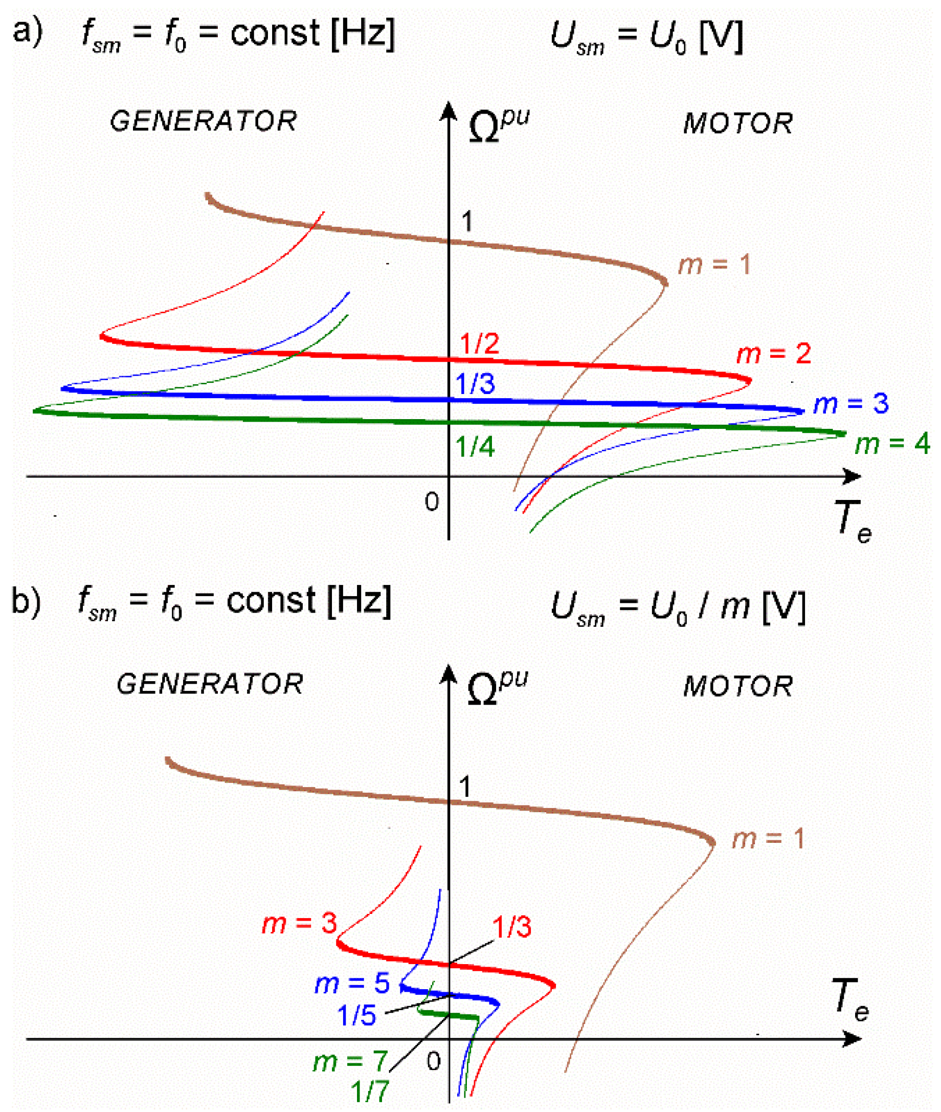
The mechanical characteristics of a multiphase induction machine indicate the area of work of the multiphase induction generator. Figure 2 shows two typical families of mechanical characteristics of multiphase induction motors using the example of a nine-phase motor from [12]. These families are characteristic of two types of stator windings.
The mechanical characteristics from Figure 2a are typical for MIMs with the winding called here the first type of multiphase winding, whereas the characteristics from Figure 2b are typical for MIMs with the second type of winding. All the characteristics in Figure 2 for a given were determined for the same current frequency and the RMS phase voltages shown in the figures. For the first type of winding, the voltage is constant , whereas, for the second type of winding, the voltage must be diminished almost proportionally to m (), assuring the same level of machine core magnetization. The shape and course of these characteristics for the generator mode show that, at different speeds, only the MIM with the first type of winding enables maintaining the same voltage and frequency by switching the sequence of phase currents. A multiphase machine with the second type of winding can work, in practice, with the sequence m = 1.
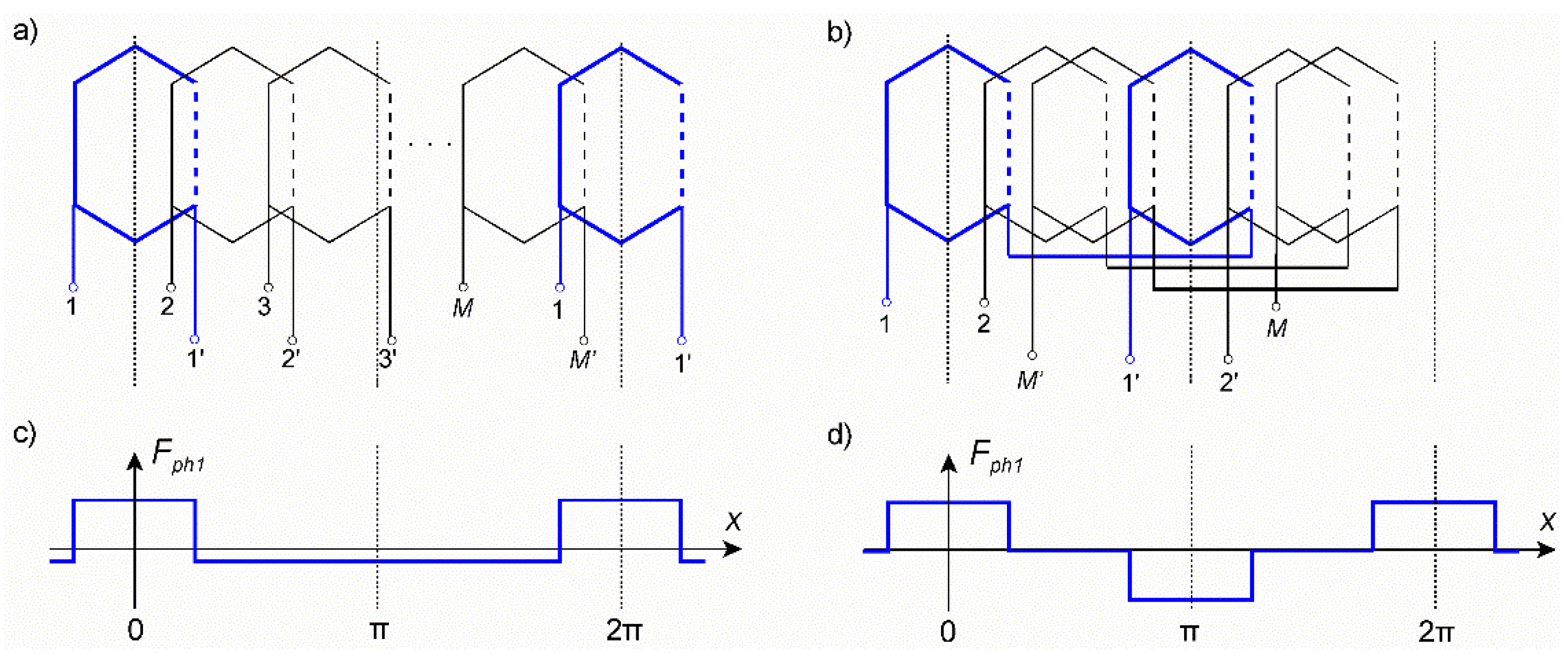
Both types of multiphase windings have a symmetrical structure, and they differ in the produced MMF harmonic spectrum. The structures of these winding are schematically shown in Figure 3a,b.
For simplicity, these phase windings are represented by single coils. In Figure 3c,d, the MMF distributions Fph1 produced by the first phase of these windings are shown. In fact, the single coils are replaced by groups of coils placed in stator slots producing a step-shaped MMF. The first type and the second type of winding are signed with the coefficient and , respectively.
The MMF distribution of k-th phase winding can be described by the following Fourier series:
where , is the current of the k-th phase winding, represents the harmonic orders belonging to the set x is the machine angle along the air-gap, is the position of the winding magnetic axis, and is the winding factor for a given . For the 2p pole phase windings mutually displaced by the angle , having the same turn numbers and the same winding factors for , the MMF distribution can be described as
The MMF of the first type of winding (S = 1, Figure 3c) has the harmonic orders ν being odd and even multiples of the number of pole pairs p. The MMF of the second type of winding (S = 2, Figure 3d) contains only harmonics orders ν being odd multiples of . Thus, the set of harmonic orders takes the form
The MMF of the first type of winding has asymmetry with respect to the x-axis, whereas MMF of the second type of winding is symmetrical. Thus, the windings for S = 1 can sometimes be called asymmetrical windings, and the windings for S = 2 can be called symmetrical.
2. Application Suggestions
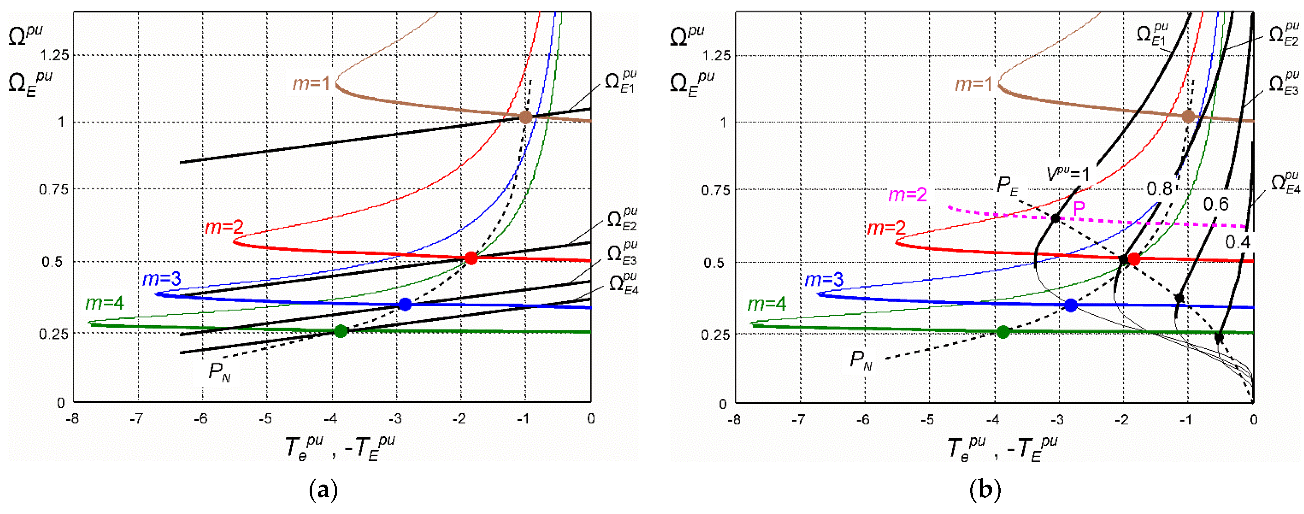
A multiphase induction generator can be driven by various engines producing a driving torque causing the rotating speed . For laboratory purposes, it can be a DC separately excited motor, and, in practical applications, it can be a wind or hydro turbine. An important feature of wind turbines is the high variability of speed caused by the load and wind speed. Water turbines have a lower variation in speed. The generator-type family of MIM mechanical characteristics corresponding to the regenerative operation and the characteristics of the driving DC motor are shown in Figure 4a. Steady operation points occur at the intersection of the MIM mechanical characteristics for m = 1, 2, 3, 4 with the characteristics of the DC motor , , , . These points correspond to the power recognized as nominal for the generator (MIM). At all operating points of the mechanical characteristics, for each value of m, the generator produces almost the same voltage and frequency. For the generator driven by the wind turbine (example), the mechanical characteristics are shown in Figure 4b. The wind turbine family of characteristics is given for various values of the wind velocity [1,7,11,13,14,15,16,17]. The black points indicate the maximum power of the turbine for a given wind velocity.
The operation of the generator at points between the MIM characteristics corresponding to given supply sequences m is possible with the frequency and voltage regulation. The largest range of speed occurs between the characteristics for sequences m = 1 and m = 2. In this range, the appropriate generator speed should be selected, at which point the supply sequence should be switched from m = 2 to m = 1 with increasing speed or switching from m = 1 to m = 2 with decreasing speed. Such switching causes a step change in the mechanical characteristics of the generator. For example, when m = 2 and speed , the generator works at frequency , whereas, at , the frequency should be increased to at a constant voltage, making the machine overload at point P (magenta curve in Figure 4b). Above this speed, there is a switch to the sequence m = 1, and the generator works with the frequency . This frequency increases to 1.0 with speed increasing to . The switching of can practically be performed by introducing a certain hysteresis range. For the speed ranges between the characteristics for the remaining pairs of the supply sequence m = 2, 3 and m = 3, 4, the switching takes place on a similar principle. To properly set the ranges of operation, some methods can be applied, e.g., maximum power point tracking [7,13,14,16] or appropriate speed choice [5].
For each sequence m, there must be voltage regulation on terminals A–B (Figure 1). A method of field-oriented control of this DC voltage was proposed in [1,7,13], whereas, in [1,6,9,18,19,20], a standalone generation system together with the grid connection was recognized. According to Figure 1, the VSC between the MIM and the DCSYS is the voltage source inverter. Such a converter system was analyzed among others in [1,5,7,8] for multiphase induction machines. However, three nonconventional solutions for voltage control of variable-speed induction generators were proposed in [16,20,21]. The multiphase induction and synchronous generators can produce the output voltage at broken phase connections tolerating the machine or converter damages [17,22,23].
The control system proposed in this paper is based on direct regulation of the machine frequency dependent on the electromagnetic torque and the actual speed. The DC voltage is regulated in the output of the PWM rectifier (VSC in Figure 1) and is similar to the method presented in [6]. The proposed method of voltage control is relatively simple as it emphasizes the advantages of voltage control with the use of phase current sequence switching.
Recently, multiphase induction machines were considered as six-phase solutions (applications) [9,17,18,20,24,25,26] with so called symmetrical and asymmetrical stator windings. The modeling and the control of six-phase generators with a symmetrical stator winding were presented in [17,26], whereas results for those with an asymmetrical stator winding were presented in [9,20,24]. The symmetrical winding has the phases displaced mutually with 60 electrical degrees, while the asymmetrical one has a 30 degree displacement. According to the rules of symmetry, both are symmetrical. Asymmetry can appear, e.g., due to different resistances or inductances of the windings. A better nomenclature is “double stator winding” and the other names proposed in [18].
The MMF of the winding of the first type (Figure 3a,c) has the features of axial asymmetry, while the distribution of the MMF of the winding of the second type is symmetrical in this respect (Figure 3b,d). The properties of the multiphase induction generators, resulting from the magnetic field distribution, are presented in the next sections. They are proven by means of appropriate measurements, for which the guidelines were obtained on the basis of simulations using the computer model presented in [3]. Simulation results were not necessary to be presented in this paper.
3. Properties of MIMs and the Induced Generator Voltage
3.1. MMF Distribution and Main Properties
The influence of both winding types on a multiphase induction machine can be determined by analyzing the traveling total MMF caused by supplying monoharmonic currents (Equation (1)). The total MMF is the sum of phase MMFs for all phase windings.
This expression can be written as a sum of two MMF components,
where
These MMF components have nonzero values for the harmonic orders marked under the summation sign. The amplitudes of the MMF harmonics for orders have the values
Both MMF waveforms and travel with specific rotating speeds. These speeds can be determined for the steady state when constant and . Equating the arguments of and to zero, we obtain angular speeds for each harmonic field of and , respectively: and . Hence, for each , the harmonic components of and travel in mutually opposite directions. For each , the only value that changes the harmonic orders is the sequence number of the supply currents , where has to be omitted as not useful. Let us analyze for harmonic orders and for . The greatest and the most important harmonics are for the orders when . Thus, the steady-state MMF monoharmonic waveforms in Equations (13) and (14) for forward sequence numbers in Equation (2) and the winding of the first type S = 1 assume the following forms:
for
for
Waveform rotates with the speed , which is faster than rotating with the speed . For the numbers of backward supply sequence (Equation (3)), we get the reversed situation for , . Now, the speeds assume the following values: , .
For S = 2 (second type of winding) the set of harmonic orders (Equation (7)) having only odd numbers is different than for S = 1. This means that, for subsequent sequence numbers , the harmonic orders must assume values and . The angular speeds corresponding to these orders are and . For the numbers of backward supply sequence , we get the reversed situation using the same principle as before for S = 1.
One of the magnetomotive forces or should be dominant at the sequence number or , causing the unambiguous resultant speed of the rotating field. This depends on the amplitudes of and dependent on the ratio . For and , the multiphase winding must be designed assuring [27]. In such a way, the dominant force is , whereas , playing a parasitic role at this time, rotates oppositely with a lower speed and a lower amplitude. This means that, simultaneously, creates pole pairs, and creates pole pairs. Thus, by setting the sequence number of currents in Equation (1) to the value
for each (Equation (4)), resultant speeds of a positive direction are obtained.
The respectively opposite speed to Equation (18) appears when dominates. This becomes the case for . Then,
As an example, we have the induction machine with the number of stator phases and the number of pole pairs . According to Equation (4), the maximum number of forward sequences is . The machine with the first type of winding (S = 1) has three positive no-load speeds for the supply sequence numbers = 1, 2, and 3: and . Opposing speeds for this winding type occur for sequence numbers m = 6, 5, and 4: , , and . For the second winding type and the same number of phases, we have no-load positive speeds for m = 1, 3, and 5: , , and , whereas, for = 6, 4, and 2, we have the corresponding negative speeds: , , and .
The nine-phase induction machine (, ) has the maximum number of forward sequences . For the first type of winding , = 1, 2, 3, and 4, , , , and . Opposing speeds occur for sequence numbers = 8, 7, 6, and 5, respectively. For the winding of the second type , = 1, 3, 5, and 7, , , , and . The corresponding opposing speeds occur for sequence numbers = 8, 6, 4, and 2.
To illustrate the above considerations, the distributions of the magnetomotive force generated by the first () and second type () of nine-phase windings () were determined. The schemes of the windings are presented in Figure 5 and Figure 6, respectively, whereas the MMF distributions are shown in Figure 7 and Figure 8 [27].
The winding factor for harmonics was calculated according to
The angles and are indicated in Figure 5 and Figure 6, and is the number of coils in the group creating the phase winding (here, = 2). For a typical three phase winding, it is the number of slots per pole per phase, usually denoted as q. For the first type of winding (Figure 5) S = 1, = 1, 2, 3, and 4, while = 8, 7, 6, and 5. For the second type winding (Figure 6) S = 2, = 1, 3, 5, and 7, while = 17, 15, 13, and 11. To show that dominates over , the values of ratio are presented in Table 1. They are greater than . Additionally, this explains the change in MMF amplitudes seen in Figure 7 and Figure 8.
This table shows that the dominant component of MMF is , since, for all m, . The values in Table 1 explain the smaller variation of the MMF amplitude for the first type of winding (S = 1) than for the winding of the second type (S = 2) with a variable supply sequence. For the first winding, the ratios are on a similar level for m = 1, 2, 3, and 4, whereas, for the second winding, this ratio is several times greater for m = 1 than for the remaining m = 3, 5, and 7. Additionally, the presented values explain why the mechanical characteristics of a multiphase machine with the winding of the first type (Figure 2a) were determined for the same voltage, while the characteristics for the machine with the winding of the second type (Figure 2b) had to be determined for different voltages.
3.2. Induced No-Load Voltage
The resultant magnetomotive force due to the magnetizing current is described by the relationship in Equation (8) or the form in Equation (9). Thus, the traveling waveform of the flux density in the air-gap,
excites the voltages in the machine windings, where is the equivalent width of the air-gap, and H/m. The voltages are time derivatives of the winding flux linkages. These flux linkages of entire windings should be calculated as the sums of the fluxes linking each of the turns. Instead, these flux linkages can be calculated using substitutional sinusoidal windings. Generally, the winding produces the MMF described by Equations (5) or (6). This means that the MMF determined for a harmonic order can be produced by series connection of elementary sinusoidal windings of the pole pitch and the conductor density.
where , , and .
Flux linkage of the k-th phase winding can be calculated according to the formula developed in [28].
where is the axial coordinate of the machine, is the length of the stator core, and is the stator core bore radius. The term is time-dependent. Thus, the time derivative of Equation (23) for the harmonic order gives the induced steady-state no-load voltage.
The same expression can be obtained from the equivalent circuit of the multiphase induction machine presented in [29]. In Equation (24), the dependence on coordinate is omitted (e.g., omitted influence of the rotor bar skew). Introducing , the amplitude of induced voltage has the following value for (Equation (18)):
where
For the speed considered nominal at m = 1, the induced voltage is . Now, it is apparent that, even if the speed of the generator decreases by a factor of m to , the voltage amplitude can be increased by switching the supply sequence to m, whereby the voltage then returns to the value as at with the same .
For example, we have the magnetic core of a 4 kW induction machine with a nine-phase winding (Figure 5) placed in 36 stator slots (based on the magnetic core of Sf112M-4). The cage rotor has 28 aluminum bars and the following parameters: 9, , H/m, 0.055 m, 0.12 m, 110, 2.5 A, and 314.16 rad/s for the speed rad/s, not exceeding the maximum one ( Hz, rev/min). The amplitude of the phase voltage (Equation (25)) at is V. The flux is , and the RMS voltage is V.
Observing values of the coefficient in Table 1, it is clear that only the induction generator with the first type of winding can have its voltage changed by the supply sequence switching. This coefficient appears in Equation (25) for and its value changes from 0.248 for m = 1, through 0.182 for m = 2 and 0.103 for m = 3, to 0.041 for m = 4. This means that, to obtain the same voltage at m = 2 as at m = 1, the magnetizing current has to be increased about 1.36-fold. At m = 3, the current has to be increased 2.4-fold. This results from the simplified expression in Equation (25) which takes into account only one harmonic of the magnetic field of the order . In fact, such a large increase in the magnetizing current does not occur [25], even at m = 4. Equation (25) simply shows the basics of the voltage step change with the parameter m.
4. The Control System
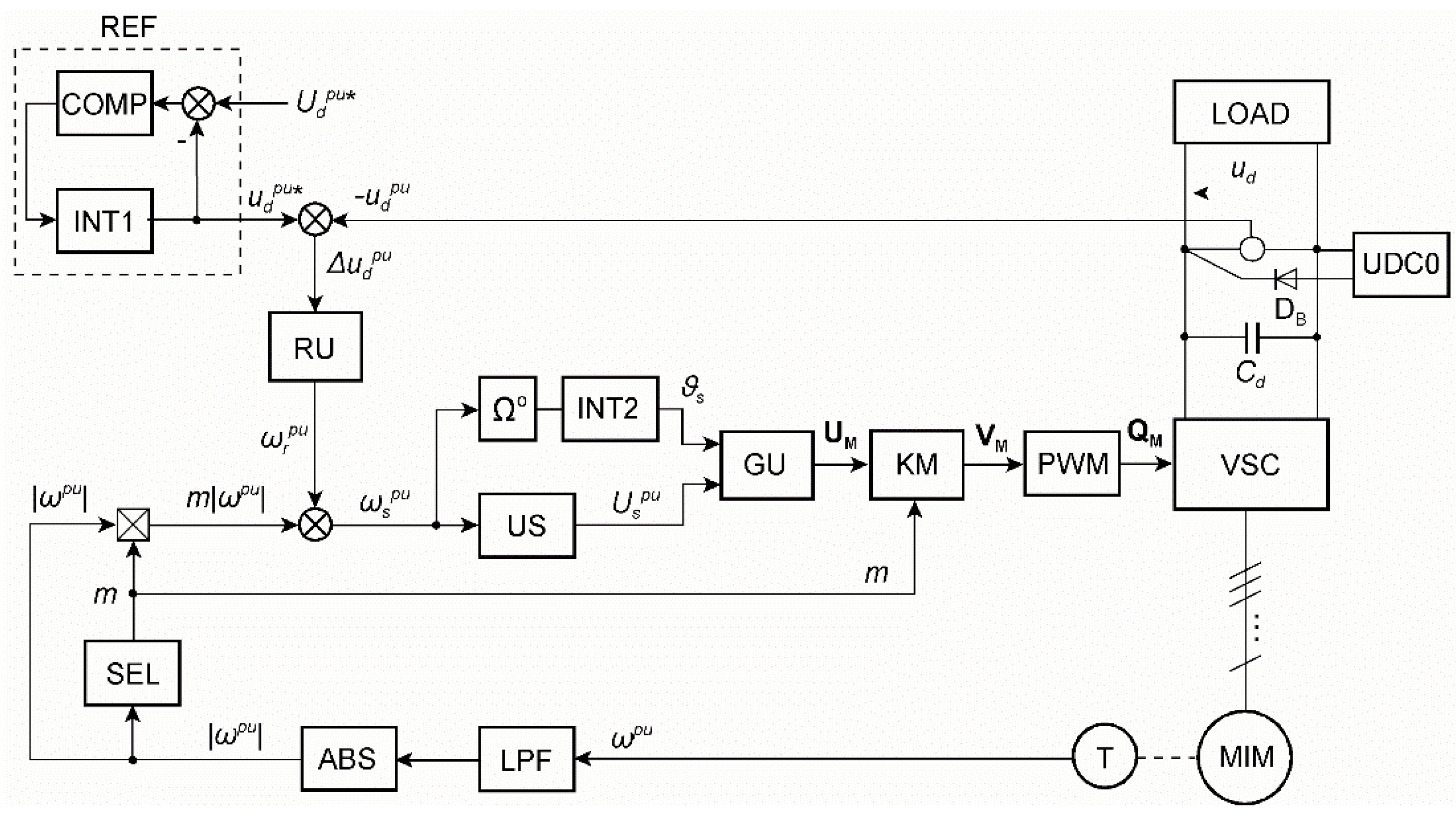
As mentioned in Section 1, the control idea is derived from the speed control method presented in [2,4]. Instead of a speed controller, a DC voltage controller is applied. The idea of the control system is presented in Figure 9. It is a kind of development of the system shown in Figure 1.
The induction generator is a multiphase MIM induction machine with a stator winding ST connected to a VSC, while the rotor of a squirrel-cage motor RO is driven by a GE engine at an angular speed , directly or by a gear box GB. The output voltage of the capacitance in the DC circuit of the VSC converter is controlled by the CTRL.
The task of the CTRL is to develop impulses controlling the valves of the VSC voltage source converter working as a pulse rectifier for the DC circuit, while the voltage on the capacitance supplies the LOAD. This load can be any two-terminal system or a static converter that produces a standard voltage at the output, e.g., voltages of a three-phase system with a specific amplitude and frequency connected to the power grid (so-called grid converter). Parallel to the capacitance, the circuit UDC0 is connected to maintain the minimum voltage of this capacitor. The controlled output voltage, expressed in relative units (in relation to the base reference voltage ), should satisfy the dependence , where is the desired signal for .
The control system CTRL is schematically presented in Figure 10.
At the base angular frequency (, —base frequency in Hz) the motor speed , the stator angular frequency and the rotor angular frequency assume the following relative values:
According to Equation (18) the p.u. no-load speed of the machine is at . For the machine speed , . Thus, for the sequence number , the stator p.u. frequency is related to the rotor p.u. frequency by the relationship
The machine slip for a given is then
The p.u. amplitude is generated by US according to Equation (25), where with the base voltage amplitude and the base magnetic flux . Defining the average magnetic flux for all and taking into account Equation (28) we have
The following values can be used for a nine-phase machine: , , or .
The voltage controller RU can be P type with limited output or PI with saturation. The input signal is the control error , while the output is the p.u. rotor frequency signal proportional to the electromagnetic torque. The saturation of RU was set to , where is the slip in Equation (29) at which maximum torque occurs when and .
In the INT2 block, the phase angle is calculated as
Hence, the block GU generates the vector of M phase monoharmonic signals having the amplitude and phase .
The vector signals have the first sequence ().
The sequence of signal in the vector UM, depending on the parameter , is changed after passing through the KM block. This operation takes place according to the following signal conversion:
The conversion matrix has a specific form for a given number of phases , e.g., for ,
In this case, the parameter can assume the values = 1, 2, 3, and 4. The coefficients of the matrix take the value = 1 only for a given , i.e., for , while . Similarly, for , there is , while , etc. The empty cells in the matrix have the value 0. For a five-phase system ( = 5), there is , for a seven-phase system ( = 7), there is = 1, 2, 3, and, for = 12, there is = 1, 2, 3, 4, 5. The relevant matrices are shown below.
The PWM block works as the comparator with one carrier triangle signal and the modulating signals in Equation (33). The multiphase system at seems to be a better and more accurate solution than the PWM modulator. Its operation is based on a comparison of all signals with the triangle . For the k-th half-bridge of VSC in Figure 9, the 0–1 output signals of PWM can be described as . triggers on the switch TkG and triggers off TkD and vice versa. In this description, the function can be treated as an ideal comparator. The algebraic signals can be easily changed to logical ones.
The block SEL selects the sequence number dependent on the actual speed of the induction generator. Selector work ranges are presented in Table 2. Switching between the sequence numbers must be done by introducing hysteresis margins. The low-pass filter LPF protects SEL against unwanted switching of .
5. Laboratory Tests of the Nine-Phase Induction Generator
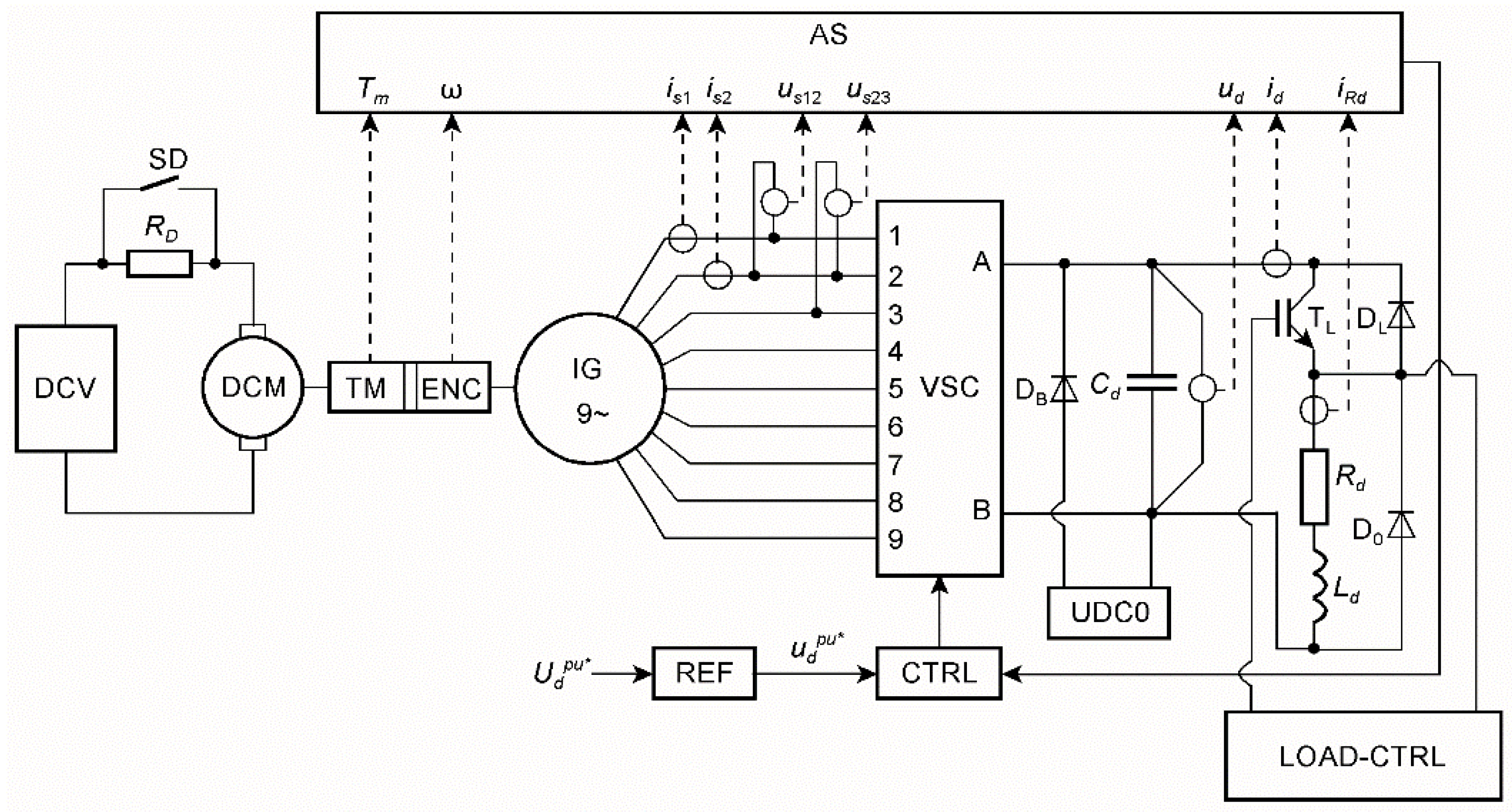
The operation of the nine-phase induction generator () was tested on a laboratory stand. A machine, previously tested as an electric motor [2,3], was used for this purpose. The machine was built on the magnetic circuit of a 4 kW Sf112M-4 three-phase induction motor, using the first type of stator winding shown in Figure 5 and leaving a squirrel cage rotor with 28 cage bars.
For measurement purposes, the generator power was reduced to = 1000 W at , = 5.3 A (rated RMS stator current), = 150 V (rated mean DC output voltage), = 33.3 Hz (rated frequency), and = 209 rad/s (rated speed, maximum speed). The RMS stator phase voltage was = 67.5 V and the mean DC rated current was = 6.67 A. The generator was driven without a gearbox. Thus, and . The rated speed was taken as the reference speed , and the rated voltage was the reference voltage for control purposes.
5.1. Measuring System
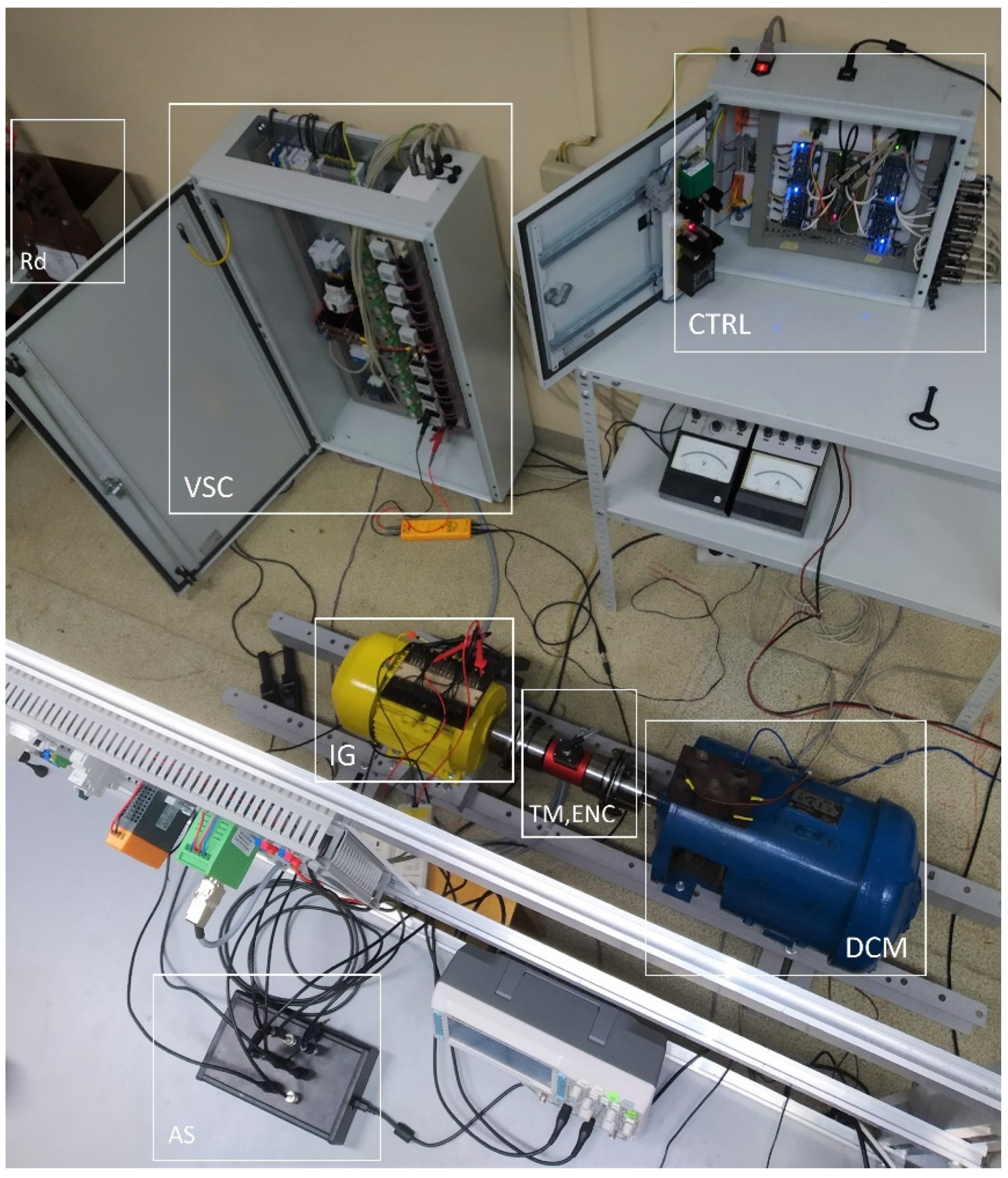
The scheme of the measuring system is shown in Figure 11, and a photo of the laboratory stand is shown in Figure 12.
The main parts of the test bench are listed below.
- Torque meter and encoder (TM, ENC): quadrature encoder 720 imp/rev with the speed sensor built-in DATAFLEX 32/300 torque meter.
- Control system (CTRL) based on digital signal controller: Texas Instruments TMS320F28379D.
- IGBT modules (VSC): Mitsubishi CM50DY-24H.
- Current measurement probes: Chauvin Arnoux E3N; voltage measurement probes: TESTEC TT-SI 9001, PINTEK DP-35.
- Data acquisition card (AS): National Instruments USB-6211.
- DC commutator motor (DCM): 4.5 kW, 220 V, 1460 rev/min.
- UDC0 charges capacitor Cd to initial voltage of = 80 V.
The IG generator was driven by a DC motor. The generator load was the resistance Rd and the inductance Ld, powered by a DC chopper regulated by the width of pulses controlling the TL transistor. The instantaneous generator output power supplied the load, while the generator was driven by mechanical power , where . The measured mechanical torque . The AS system enabled the measurement of quantities listed on inputs in transient and steady states.
5.2. Experimental Tests
The voltage control system shown in Figure 10 used the simplest method of setting the magnetic flux by proportional adjustment of the phase voltage to the frequency. This provided continuous control combined with step control by switching the winding supply sequence changing the number of pole pairs. Below are the results of the laboratory tests that demonstrate controllability with some limitations.
5.2.1. Steady-State Measurements
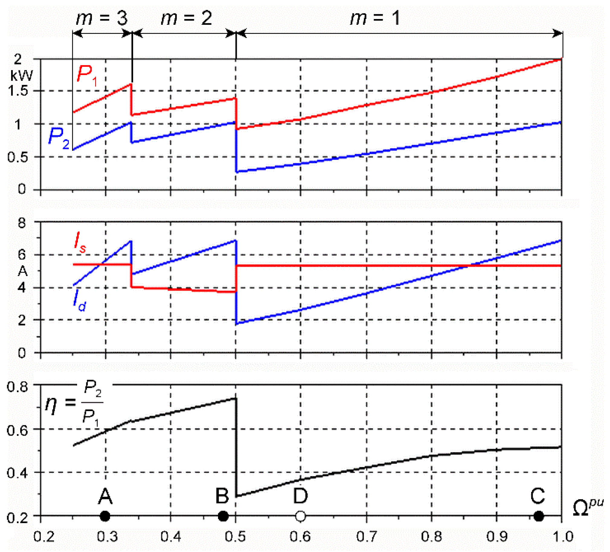
For the steady state, the generator speed was set in the range . The following values were measured: , , , , , , , , and . A constant value of the output voltage was controlled by an input signal . The switching took place for the following speed ranges (Table 2): for , for , for , and for . The measured steady-state characteristics are presented in Figure 13.
The steady-state characteristics were measured with voltage regulation to a constant value . Depending on the speed range, the sequence number was switched. The generator load was regulated in such a way that the RMS value of the stator current was kept between 0.75 and . This resulted in a load reduction at lower speed. For , the results are not presented because, with the assumed load, it was not possible to generate the desired voltage. With this sequence, the machine produced eight poles, resulting in a high magnetizing current. This current would have to be greater than the rated current at rated output voltage.
In the range of relative speed = 0.25... 0.5, the machine worked at = 2 and 3. The best efficiency of = 0.74 was obtained with = 2 and = 0.5. With = 3 and = 0.25, the efficiency dropped to 0.52. Operation in the range marked for = 2 could be partially performed at = 3 and a higher frequency than the rated one, and vice versa.
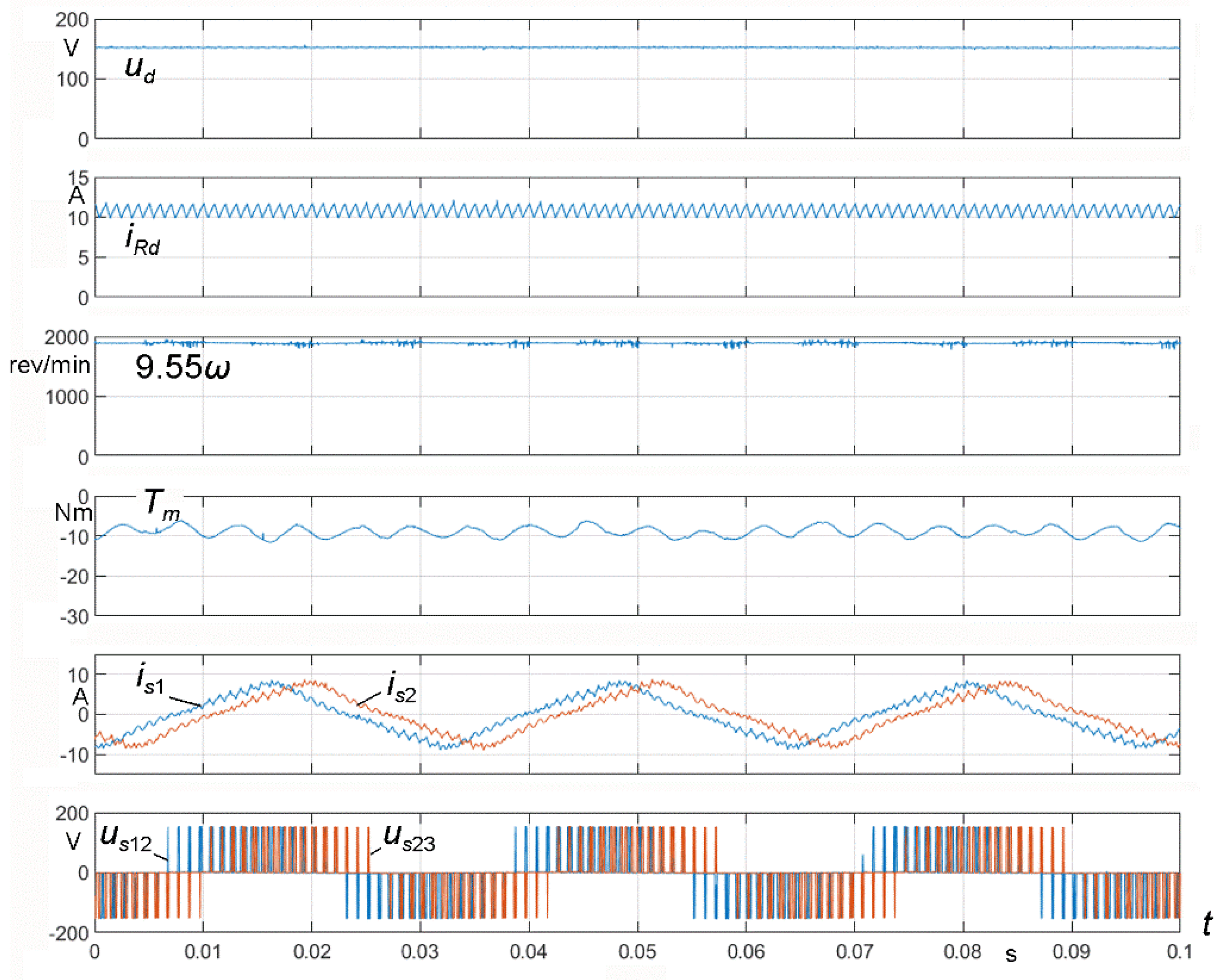
Operation at = 1 took place in the range = 0.5... 1. This interval was the largest for operation with one supply sequence. Although a constant voltage was obtained in the whole range, but at the speed of = 0.5, the efficiency of the system decreased dramatically to = 0.3. Higher efficiency = 0.63 was obtained with = 2 and speed = 0.6 (case D in Figure 13), but at the cost of significant current distortion from the sinusoid. Then, the machine worked with the weakening of the magnetic field.
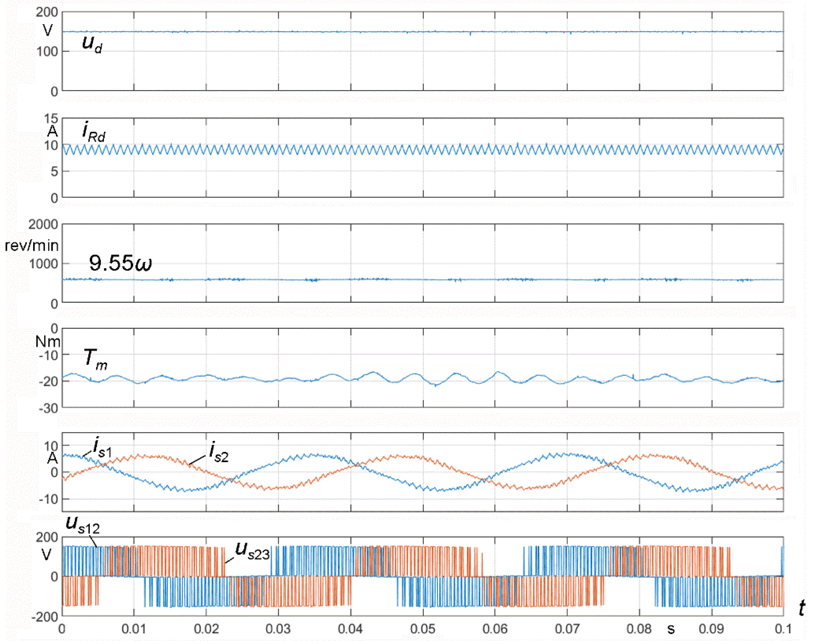
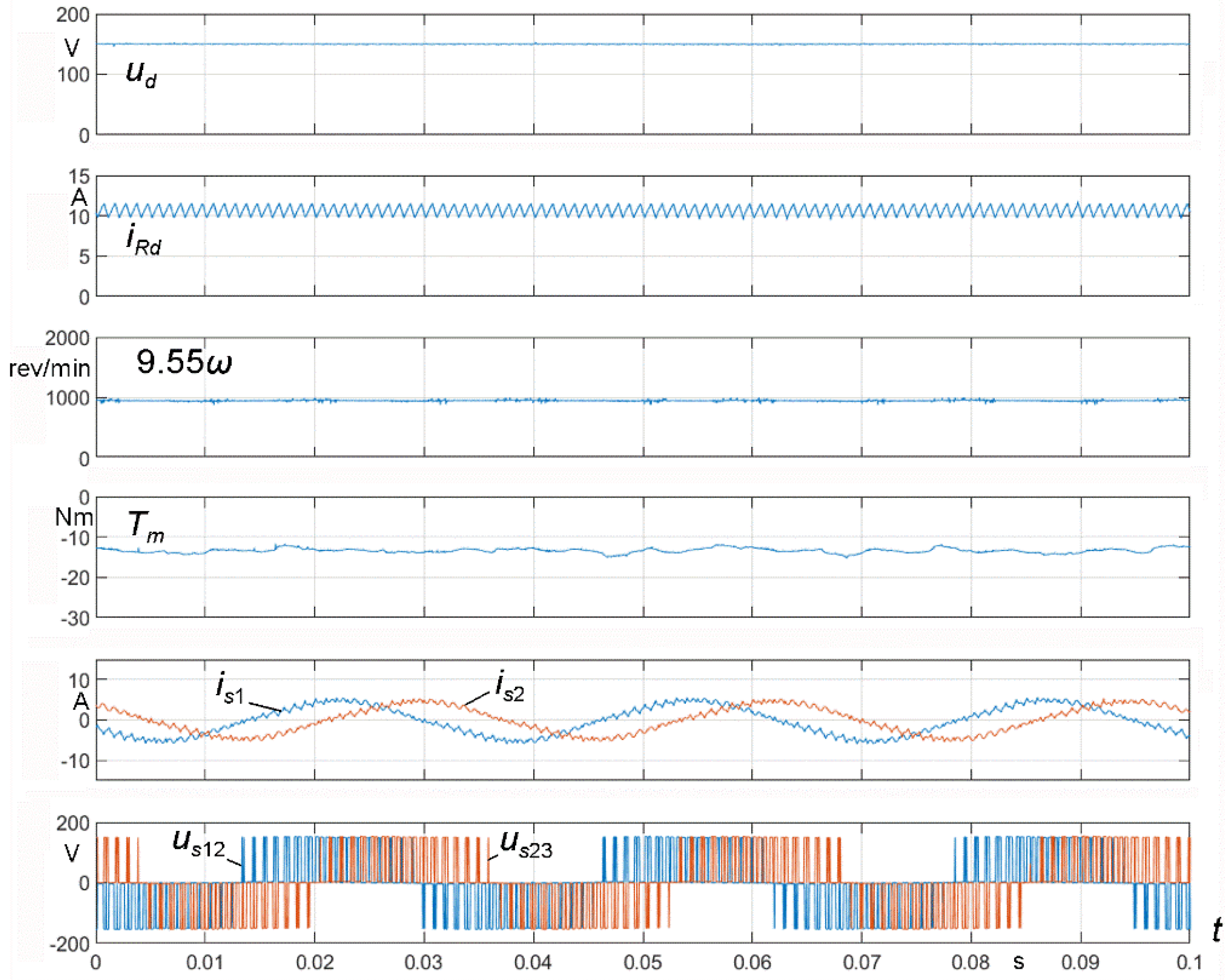
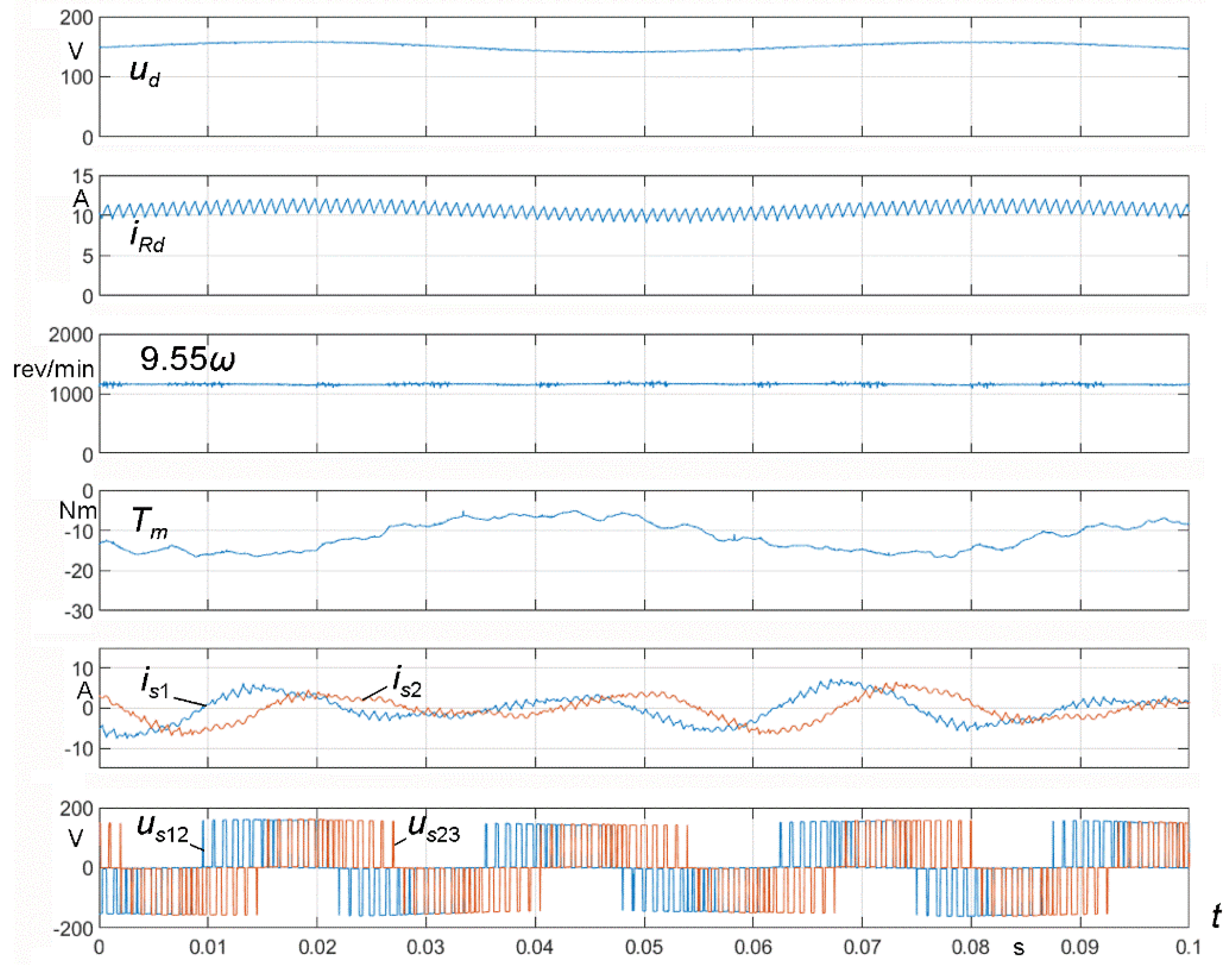
The actual operation of the generator is illustrated in the cases marked A, B, C, and D in Figure 13. The waveforms , , , , , , , and were recorded in the steady state, and the results are shown in Figure 14, Figure 15, Figure 16 and Figure 17.
The work for cases A, B, and C was stable, as the voltage was kept at the set level. The torque showed a slight undulation. For A and B, the phase currents were sinusoidal, but, for C (Figure 16), the currents were triangular. The greatest disturbances in the phase and moment currents, as well as the oscillations of the output voltage and current, occurred in case D (Figure 17). The necessary field weakening in this case was obtained with PWM overmodulation. The advantage, however, is that the desired voltage level was obtained with twice the efficiency of = 1.
5.2.2. Example of Transient States
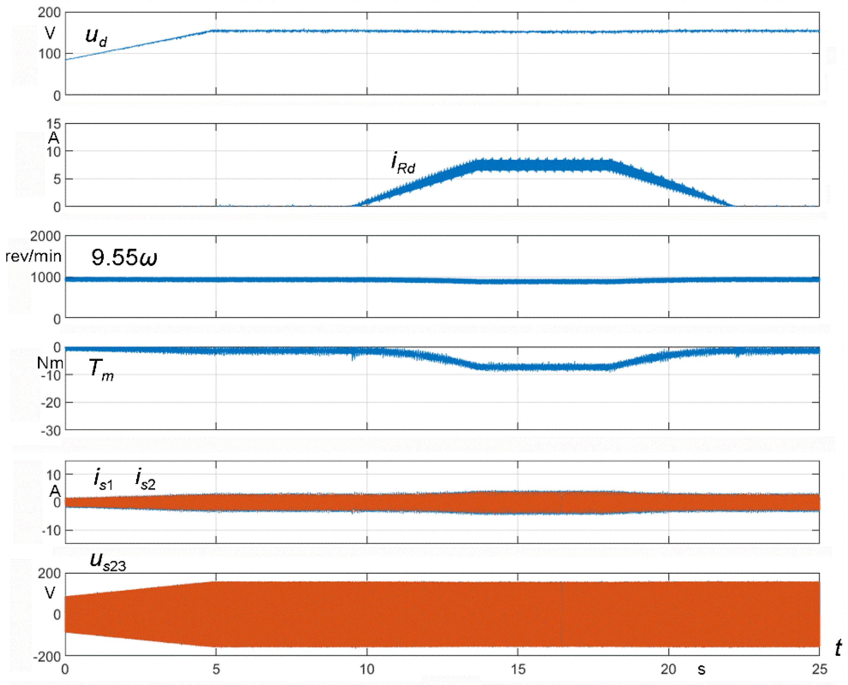
Figure 18 shows the excitation course of the generator driven at constant speed to the desired voltage = 150 V. After excitation, the load was increased to the power ≈ 500 W. In the 0 s to 5 s time interval, the voltage ramped up linearly from to . The generator was not loaded. The load was increased after 10 s, and the generator was unloaded again after 22 s. All the time, the generator voltage had a constant set value.
6. Conclusions
From the point of view of voltage regulation, a multiphase induction generator can be driven with any speed, and the voltage can be kept at a desired value. However, when the driving engine does not have a stiff mechanical characteristic, the voltage control must be performed with respect to utilization percentage of the system to produce maximum power. This power can be obtained at a high speed and a low torque, and vice versa. The only problem is the possibility of delivering proper torque resulting from the stable parts of mechanical characteristics of the driving engine (turbine).
The characteristics presented in Figure 13 show that, for the tested generator, the best operation occurred at = 2 and = 3. With = 1, the generator speed range was too large, from = 0.5 to = 1, in which the voltage had to be regulated to a given value. This range could be divided into operation at = 1 and = 2 assuming a limited speed (Table 2) = 2/3. However, worse operation of the generator at = 2 (Figure 17) should be taken into account.
When considering the generator’s drive by means of a wind turbine, it is possible to take into account Figure 4b, where the typical characteristics of the turbine and the characteristics of a multiphase generator were presented. The figure showed that, at different wind speeds, the generator characteristics for = 2 and = 3 were closest to the points of maximum power of the turbine. It follows that the generator should have an optimally designed stator winding with regard to the maximum magnetomotive force at = 2, 3, as well as at = 4. In that case, it would be almost impossible to work with = 1 [27], and the machine would be quite different from the one that was tested. For example, much better properties are obtained using a two-layer winding with the same pitch as the winding in Figure 5. The design can also use the methodology presented in [30,31].
Advantages of using multiphase induction generators are formulated below.
- A step change in voltage by switching the sequence of phase currents, causing a change in the number of poles of the magnetic field, extends the range of voltage regulation. The most useful is switching between = 2 and 3, between = 3 and 4, etc. Switching between = 1 and 2 at the speed causes difficulties in maintaining a sufficiently high efficiency of the generator.
- A multiphase induction generator has only one winding, allowing it to work with a varying number of pole pairs 1, 2, 3, 4, … When using a Dahlander winding in a three-phase machine, the number of pole pairs can be changed in a ratio of 1 to 2.
- The dimensions of a multiphase induction machine are similar to a three-phase machine with the same power. Cage induction machines are cheaper than synchronous generators with permanent magnets, which usually have to work with a back-boost converter.
- Multiphase induction generators can be used in wind and hydropower plants at significantly variable speeds. Even at relatively low speeds, a rated voltage will be produced.
- The best efficiency = 0.74 (Figure 13) was not significantly worse than the rated efficiency of the motor Sf112M-4 = 0.88 (the stator core and the cage rotor were used for the generator), since the generator was working below its rating.
The applied scalar control system maintains the output voltage well at the set level. Similar to motors, better results can be obtained by using spatial vector control or direct voltage regulation and, eventually, sliding mode voltage control [24]. This would be important for smooth switching of the supply sequence number . When applying a vector control of the output voltage in a wide range of the generator speed, switching of the supply sequence number must be applied, since the magnetizing current cannot be increased to obtain appropriate flux and voltage because of saturation of the magnetic core.
Author Contributions
Conceptualization, P.D.; methodology, P.D.; software, D.C.; validation, P.D. and D.C.; formal analysis, P.D. and D.C.; investigation, P.D. and D.C.; resources, P.D. and D.C.; data curation, P.D. and D.C.; writing—original draft preparation, P.D.; writing—review and editing, P.D. and D.C.; visualization, P.D. and D.C. All authors have read and agreed to the published version of the manuscript.
Funding
This work presented in this paper was funded by subsidies on science granted by the Polish Ministry of Science and Higher Education for Cracow University of Technology.
Institutional Review Board Statement
Not applicable.
Informed Consent Statement
Not applicable.
Data Availability Statement
Any data presented in the paper may be obtained by contacting the authors.
Conflicts of Interest
The authors declare no conflict of interest.
Glossary
| flux density in the air-gap | |
| capacitance | |
| number of coils in the group creating the phase winding | |
| electromotive force | |
| magnetomotive force (MMF) | |
| stator frequency | |
| sets of harmonic orders | |
| current of k-th phase winding | |
| amplitude of stator phase current | |
| length of the stator core | |
| inductance | |
| number of phases | |
| supply sequence number | |
| number of sequences for one direction of rotation | |
| number of turns | |
| power | |
| number of pole pairs | |
| resistance | |
| stator core bore radius | |
| indicator of machine winding type | |
| torques | |
| voltage | |
| wind velocity | |
| number of stator slots | |
| slot angle | |
| pitch angle | |
| equivalent width of the machine air-gap | |
| phase angle | |
| vacuum permeability | |
| harmonic orders of MMF Fourier series | |
| magnetic flux | |
| instantaneous rotational speed | |
| steady-state rotational speed |
References
- Boldea, I. Variable Speed Generators (Electric Power Engineering Series); CRC, Taylor&Francis Group: Abingdon, UK, 2005; p. 552. ISBN 0849357152. [Google Scholar]
- Drozdowski, P.; Cholewa, D. Frequency control of a 9-phase induction motor at switched supply sequence. In Proceedings of the International Symposium on Electrical Machines (SME), Andrychów, Poland, 10–13 June 2018. [Google Scholar]
- Cholewa, D.; Drozdowski, P. Simulink modeling of multiphase induction motors. In Proceedings of the 14th Selected Issues of Electrical Engineering and Electronics (WZEE), Szczecin, Poland, 19–21 November 2018. [Google Scholar]
- Drozdowski, P.; Cholewa, D. Natural fault tolerance of a nine-phase induction motor drive operating at variable frequency and switched supply sequence. In Proceedings of the 15th Selected Issues of Electrical Engineering and Electronics (WZEE), Zakopane, Poland, 8–10 December 2019. [Google Scholar]
- Chen, Z.; Guerrero, J.M.; Blaabjerg, F. A review of the state of the art of power electronics for wind turbines. IEEE Trans. Power Electron. 2009, 24, 1859–1875. [Google Scholar] [CrossRef]
- Kumsuwan, Y.; Srirattanawichaikul, W.; Premrudeepreechacharn, S. A simple voltage and frequency control of VSI-inverter-fed self-excited induction generator drive. In Proceedings of the ICROS-SICE International Joint Conference, Fukuoka, Japan, 18–21 August 2009; pp. 430–434. [Google Scholar]
- Jakubowski, B.; Pieńkowski, K. Analysis and synthesis of converter control system of autonomous induction generator with field oriented control. Arch. Electr. Eng. 2013, 62, 267–279. [Google Scholar] [CrossRef]
- Levi, E. Advances in converter control and innovative exploitation of additional degrees of freedom for multiphase machines. IEEE Trans. Ind. Electron. 2016, 63, 433–448. [Google Scholar] [CrossRef] [Green Version]
- Chinmaya, K.A.; Singh, G.K. Modeling and experimental analysis of grid-connected six-phase induction generator for variable speed wind energy conversion system. Electr. Power Syst. Res. 2019, 166, 151–162. [Google Scholar] [CrossRef]
- Baroudi, J.A.; Dinavahi, V.; Knight, A.M. A review of power converter topologies for wind generators. Renew. Energy 2007, 32, 2369–2385. [Google Scholar] [CrossRef]
- Mengjie, L.; Lingxiang, W.; Zhen, X. Control strategy of wide-speed-range doubly fed induction generator, based on stator-winding short circuited in low speed mode. In Proceedings of the 36th Chinese Control Conference (CCC), Dalian, China, 26–28 July 2017. [Google Scholar] [CrossRef]
- Drozdowski, P. Speed control of multiphase cage induction motors incorporating supply sequence. Arch. Electr. Eng. 2014, 63, 511–534. [Google Scholar] [CrossRef]
- Thongam, J.S.; Bouchard, P.; Ezzaidi, H.; Ouhrouche, M. Wind speed sensorless maximum power point tracking control of variable speed wind energy conversion systems. In Proceedings of the 2009 IEEE International Electric Machines and Drives Conference, Miami, FL, USA, 3–6 May 2009; pp. 1832–1837. [Google Scholar] [CrossRef]
- Ciupageanu, D.A.; Berbece, V.; Tîrșu, M.; Galbura, V. Modeling and control of a low power wind turbine. In Proceedings of the 14th International Conference on Development and Application Systems, Suceava, Romania, 24–26 May 2018. [Google Scholar] [CrossRef]
- Ciupageanu, D.-A.; Gheorghe Lazaroiu, G.; Barelli, L. Wind energy integration: Variability analysis and power system impact assessment. Energy 2019, 185, 1183–1196. [Google Scholar] [CrossRef]
- Ramos, T.; Medeiros Junior, M.F.; Pinheiro, R.; Medeiros, A. Slip control of a squirrel cage induction generator driven by an electromagnetic frequency regulator to achieve the maximum power point tracking thales. Energies 2019, 12, 2100. [Google Scholar] [CrossRef] [Green Version]
- Pantea, A.; Yazidi, A.; Betin, F.; Carrière, S.; Sivert, A.; Vacossin, B.; Henao, H.; Capolino, G.-A. Fault-tolerant control of a low-speed six-phase induction generator for wind turbine. IEEE Trans. Ind. Appl. 2019, 55, 426–436. [Google Scholar] [CrossRef]
- Levi, E. Multiphase electric machines for variable-speed applications. IEEE Tran. Ind. Electron. 2008, 55, 1893–1908. [Google Scholar] [CrossRef]
- Duran, M.J.; Barrero, F. Recent advances in the design, modeling, and control of multiphase machines—Part II. IEEE Trans. Ind. Electron. 2016, 63, 459–468. [Google Scholar] [CrossRef]
- Talpone, J.I.; Puleston, P.F.; Cendoya, M.G.; Barrado-Rodrigo, J.A. A dual-stator winding induction generator based wind-turbine controlled via super twisting sliding mode. Energies 2019, 12, 4478. [Google Scholar] [CrossRef] [Green Version]
- Muljadi, E.; Butterfield, C.P.; Handman, D. Dual-speed wind turbine generation. In Proceedings of the National Renewable Energy Laboratory, Prepared for A WEA Windpower ’96, Denver, CO, USA, 23–27 June 1996; p. 11. [Google Scholar]
- Prieto, I.G.; Duran, M.J.; Garcia-Entrambasaguas, P.; Bermude, M. Field-oriented control of multiphase drives with passive fault tolerance. IEEE Tran. Ind. Electron. 2020, 67, 7228–7238. [Google Scholar] [CrossRef]
- Gonzalez-Prieto, A.; Aciego, J.J.; Gonzalez-Prieto, I.; Duran, M.J. Automatic fault-tolerant control of multiphase induction machines: A game changer. Electronics 2020, 9, 938. [Google Scholar] [CrossRef]
- Amimeur, H.; Aouzellag, D.; Abdessemed, R.; Ghedamsi, K. Sliding mode control of a dual-stator induction generator for wind energy conversion systems. Int. J. Electr. Power Energy Syst. 2012, 42, 60–70. [Google Scholar] [CrossRef]
- Gonzalez-Prieto, A.; Gonzalez-Prieto, I.; Duran, M.J.; Barrero, F. Efficient model predictive control with natural fault-tolerance in asymmetrical six-phase induction machines. Energies 2019, 12, 3989. [Google Scholar] [CrossRef] [Green Version]
- Gonzalez-Prieto, A.; Gonzalez-Prieto, I.; Yepes, A.G.; Duran, M.J.; Doval-Gandoy, J. Symmetrical six-phase induction machines: A solution for multiphase direct control strategies. In Proceedings of the 22nd IEEE International Conference on Industrial Technology (ICIT), Valencia, Spain, 10–21 March 2021; pp. 1362–1367. [Google Scholar]
- Drozdowski, P. Synthesis elements of polyphase windings for cage induction motors. Arch. Electr. Eng. 1999, 48, 63–68. [Google Scholar]
- Sobczyk, T.J.; Drozdowski, P. Inductances of electrical machine winding with a nonuniform air-gap. Arch. Elektrotechnik 1993, 76, 213–218. [Google Scholar] [CrossRef]
- Drozdowski, P. Equivalent circuit and performance characteristics of 9-phase cage induction motors. In Proceedings of the International Conference on Electrical Machines ICEM’94, Paris, France, 5–9 September 1994; Volume.1, pp. 118–123. [Google Scholar]
- Abdel-Khalik, A.S.; Massoud, A.; Ahmed, S. Standard three-phase stator frames for multiphase machines of prime-phase order: Optimal selection of slot/pole combination. IEEE Access 2019, 7, 78239–78259. [Google Scholar] [CrossRef]
- Abdel-Khalik, A.S.; Massoud, A.M.; Ahmed, S. Nine-phase six-terminal induction machine modelling using vector space decomposition. IEEE Trans. Ind. Electron. 2018, 66, 988–1000. [Google Scholar] [CrossRef]
Figure 1.
Connection of the M-phase MIM with the VSC and the mechanical system MECH.

Figure 2.
Typical mechanical characteristics of multiphase induction motors at given supply sequences m: (a) motors with the first type of stator winding; (b) motors with the second type of stator winding.
Figure 2.
Typical mechanical characteristics of multiphase induction motors at given supply sequences m: (a) motors with the first type of stator winding; (b) motors with the second type of stator winding.

Figure 3.
Illustration of two types of multiphase windings composed of single coils: (a) structure of the first winding type (S = 1) where phases are single coils; (b) structure of the second winding type (S = 2) composed of single coils; (c) Fph1—magnetomotive force (MMF) distribution of the first phase corresponding to the first winding type, (d) Fph1—MMF distribution of the first phase corresponding to the second winding type (x—machine angle along the air-gap).

Figure 4.
An example of the mechanical characteristics of a multiphase induction generator: (a) driven by a DC motor; (b) driven by a wind turbine (black thick lines: stable parts of wind turbine mechanical characteristics).
Figure 4.
An example of the mechanical characteristics of a multiphase induction generator: (a) driven by a DC motor; (b) driven by a wind turbine (black thick lines: stable parts of wind turbine mechanical characteristics).

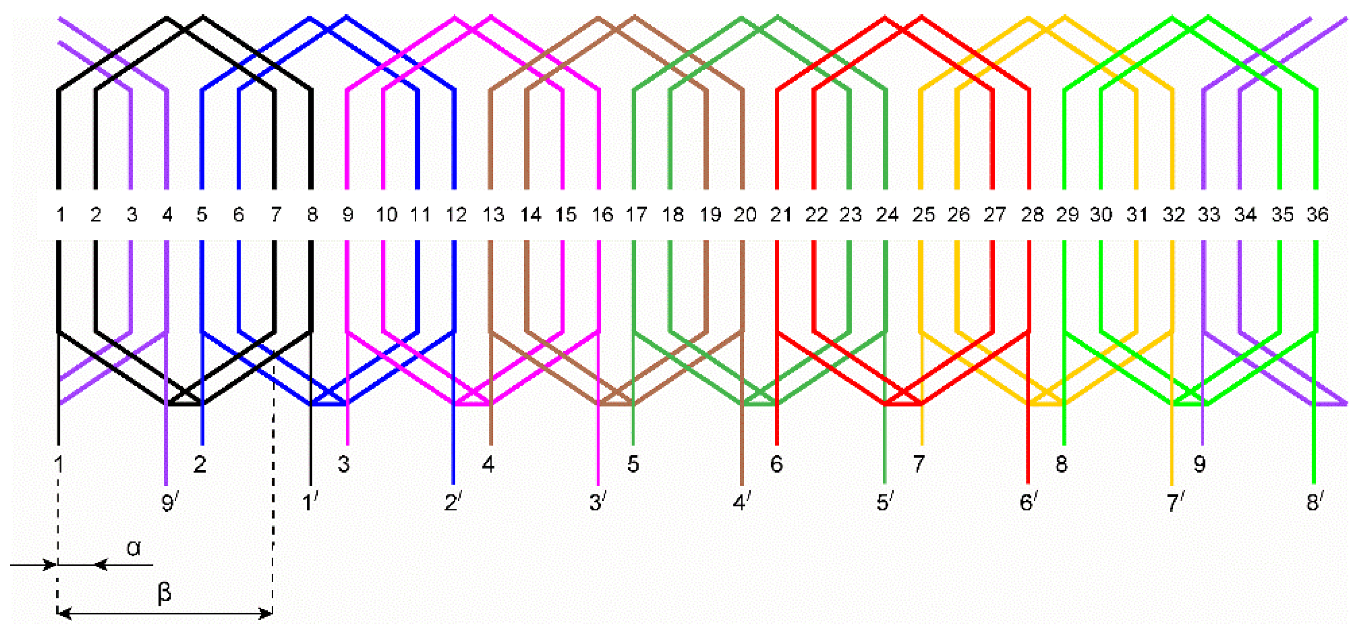
Figure 5.
Arrangement of the first type of nine-phase winding (S = 1, M = 9, cg = 2, α = 360/Zs = 360/36 ≈ 10°, β = 6α = 60°); beginnings of the phase windings: 1, 2, 3…; endings of the phase windings: 1′, 2′, 3′, …
Figure 5.
Arrangement of the first type of nine-phase winding (S = 1, M = 9, cg = 2, α = 360/Zs = 360/36 ≈ 10°, β = 6α = 60°); beginnings of the phase windings: 1, 2, 3…; endings of the phase windings: 1′, 2′, 3′, …

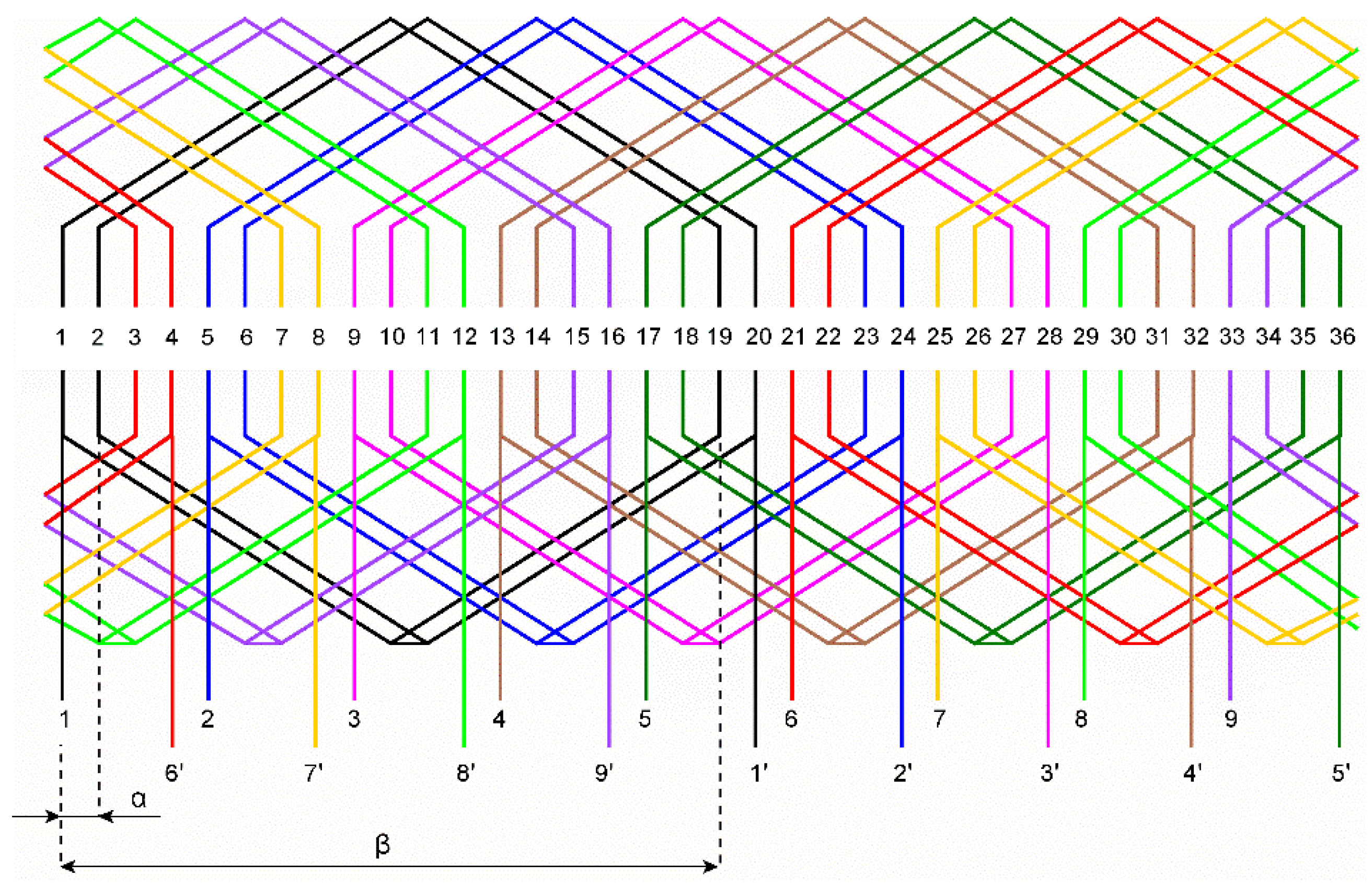
Figure 6.
Arrangement of the second type of nine-phase winding (S = 2, M = 9, cg = 2, α = 360/Zs = 360/36 ≈ 10°, β = 18α = 180°); beginnings of the phase windings: 1, 2, 3…; endings of the phase windings: 1′, 2′, 3′, …
Figure 6.
Arrangement of the second type of nine-phase winding (S = 2, M = 9, cg = 2, α = 360/Zs = 360/36 ≈ 10°, β = 18α = 180°); beginnings of the phase windings: 1, 2, 3…; endings of the phase windings: 1′, 2′, 3′, …

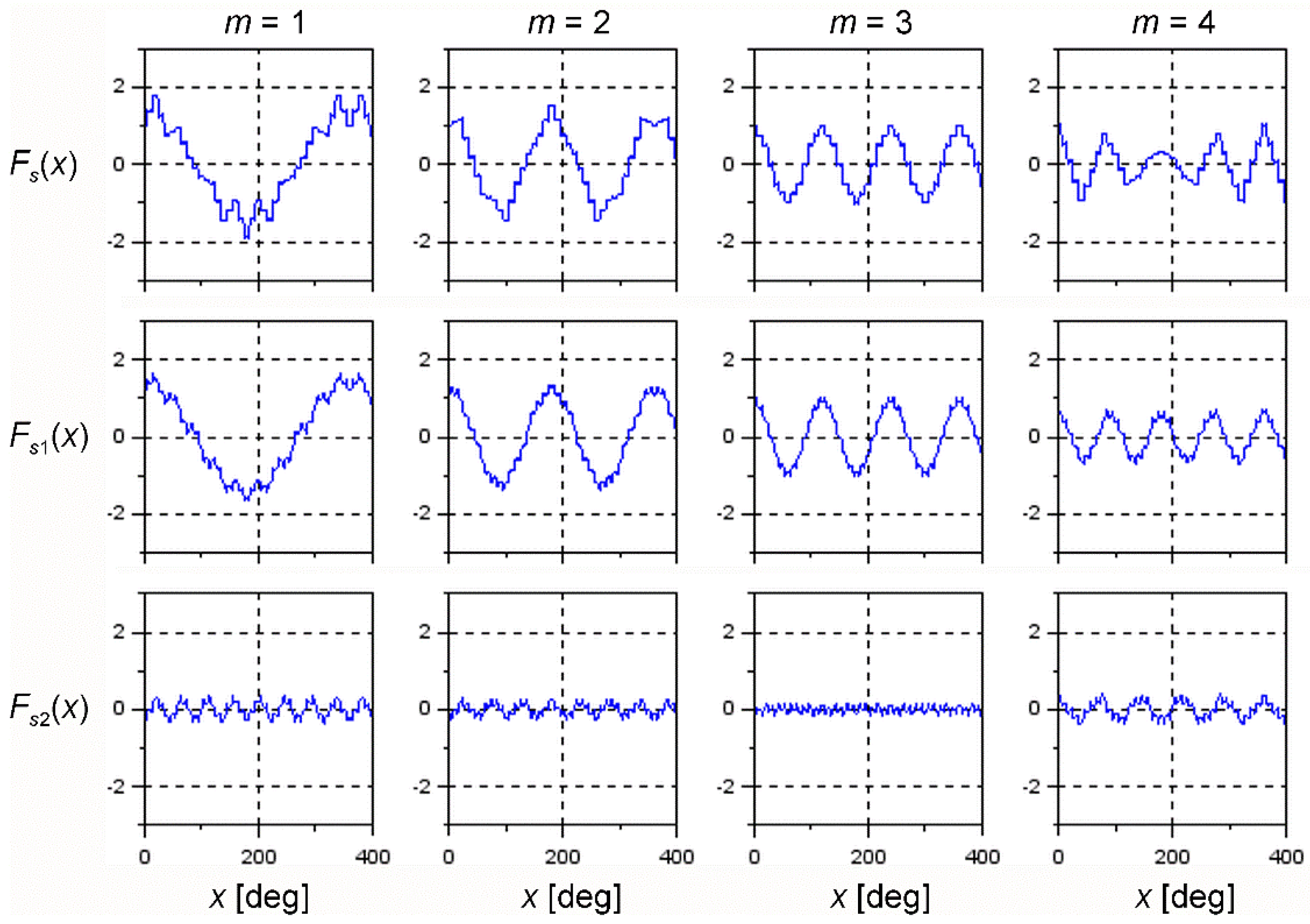
Figure 7.
Distributions of MMF for nine-phase winding (M = 9) of the first type (S = 1) at t = 0, Iμ = 1, and sequence numbers m = 1, 2, 3, and 4.
Figure 7.
Distributions of MMF for nine-phase winding (M = 9) of the first type (S = 1) at t = 0, Iμ = 1, and sequence numbers m = 1, 2, 3, and 4.

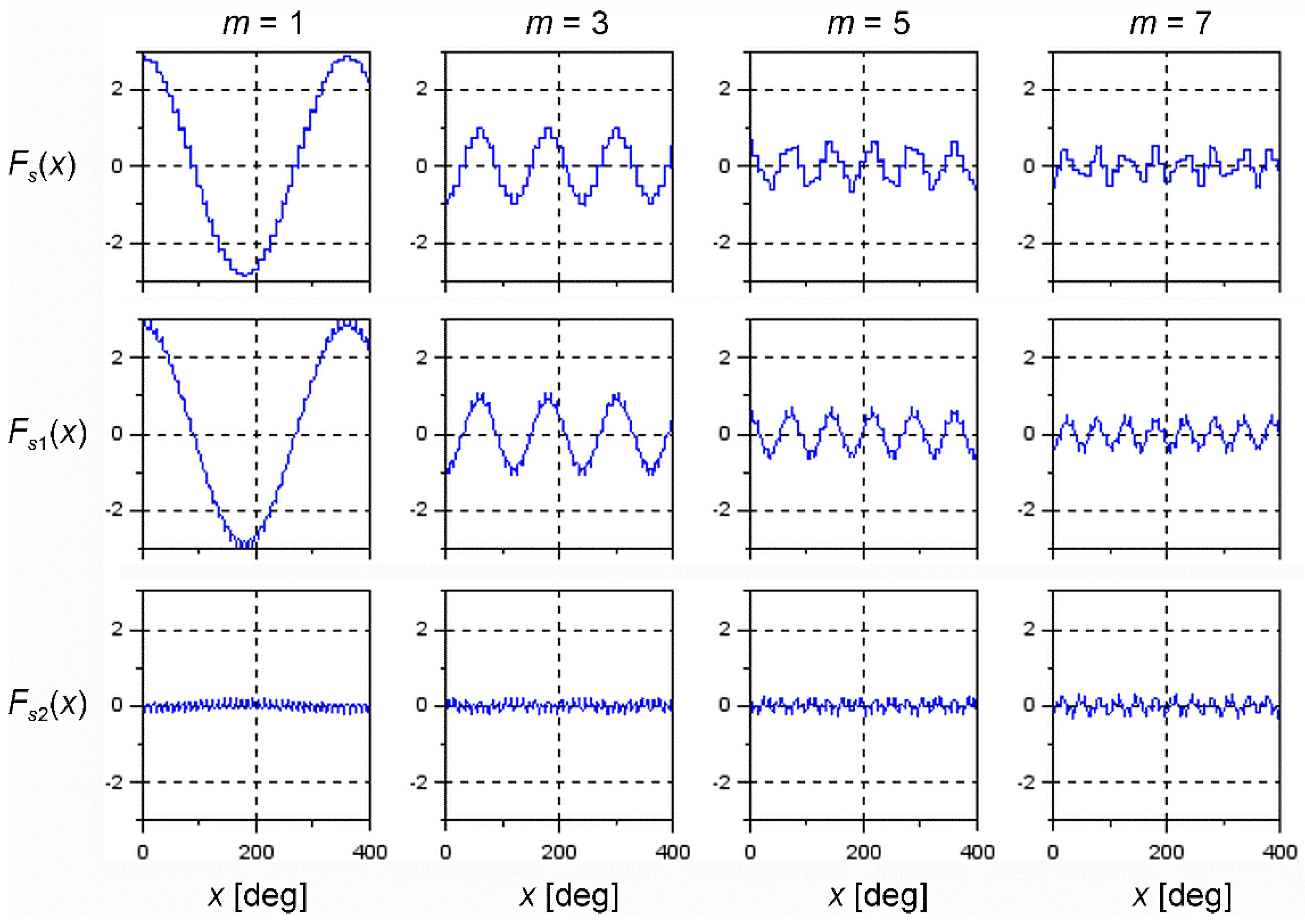
Figure 8.
Distributions of MMF for nine-phase winding (M = 9) of the second type (S = 2) at t = 0, Iμ = 1, and sequence numbers m = 1, 3, 5, and 7.
Figure 8.
Distributions of MMF for nine-phase winding (M = 9) of the second type (S = 2) at t = 0, Iμ = 1, and sequence numbers m = 1, 3, 5, and 7.

Figure 9.
Circuit diagram of a VSC connected with an MIM, operating as a multiphase induction generator: GE—generator engine (e.g., a wind or water turbine), UDC0—system assuring a minimum voltage of Cd, DB—blocking diode, LOAD—single resistance load (the simplest) power grid supplied with the grid side converter, CTRL—control system, T—speed sensor, GB—gear box (optional), ωpu—relative speed of the MIM machine related to the base reference speed Ωo.

Figure 10.
Structure of the control system: REF—voltage reference network shaping udpu* as the ramp signal, COMP—comparator, INT1—signal ramp integrator, RU—voltage controller, US—generator of voltage signal Uspu dependent on ωspu, INT2—integrator of stator frequency, GU—generator of M phase control signals, KM—switch of control signals sequence, PWM—pulse width modulator, VSC—voltage source converter, LPF—low-pass filter, ABS—absolute value changer, SEL—selector of supply sequence number m with respect of the MIM speed signal ωpu.

Figure 11.
Structure of the test bench: DCV—DC voltage supply, RD—additional resistance, DCM—DC motor driving the induction generator IG, TM—torque meter, ENC—encoder, N—star point of stator phase windings, AS—acquisition and measurement system, LOAD (TL, Rd = 8.5 Ω, Ld = 15 mH, D0), Cd = 4400 μF, DCV—controlled DC voltage supply, RD—additional resistance shorted by means of SD.

Figure 12.
Laboratory test bench view: IG - induction generator, DCM—DC motor, TM—torque meter, ENC—encoder, VSC—IGBT voltage source converter, CTRL—control system, Rd—load resistor, AS—acquisition and measurement equipment.
Figure 12.
Laboratory test bench view: IG - induction generator, DCM—DC motor, TM—torque meter, ENC—encoder, VSC—IGBT voltage source converter, CTRL—control system, Rd—load resistor, AS—acquisition and measurement equipment.

Figure 13.
Steady-state characteristics for various values of speed with a constant output voltage ud = UdN = 150 V held by the control system: P1 = TmΩ—input power, P2 = UdId—output power, Is—rms stator current, Id—mean output current, η—system efficiency, A,B,C,D—distinguished operation cases.
Figure 13.
Steady-state characteristics for various values of speed with a constant output voltage ud = UdN = 150 V held by the control system: P1 = TmΩ—input power, P2 = UdId—output power, Is—rms stator current, Id—mean output current, η—system efficiency, A,B,C,D—distinguished operation cases.


Figure 18.
Excitation of the generator at Ωpu = 0.48, m = 2 and loading to Pd ≈ 500 W.


Table 1.
Coefficients of the MMF amplitudes and the amplitude of induced phase voltages for the nine-phase windings.
Table 1.
Coefficients of the MMF amplitudes and the amplitude of induced phase voltages for the nine-phase windings.
| Parameters | First Type Winding (Figure 5) S = 1 | Second Type Winding (Figure 6) S = 2 | ||||||
|---|---|---|---|---|---|---|---|---|
| 1 | 2 | 3 | 4 | 1 | 3 | 5 | 7 | |
| 8 | 7 | 6 | 5 | 17 | 15 | 13 | 11 | |
| 0.4980 | 0.8528 | 0.9659 | 0.8137 | 0.9961 | −0.9659 | 0.9063 | −0.8191 | |
| −0.6634 | −0.4095 | 0 | 0.4531 | 0.0871 | −0.2588 | 0.4226 | −0.5735 | |
| 0.498 | 0.426 | 0.322 | 0.203 | 0.996 | −0.322 | 0.181 | −0.117 | |
| −0.083 | 0.058 | 0 | 0.090 | 0.005 | −0.017 | 0.032 | 0.052 | |
| 0.248 | 0.182 | 0.103 | 0.041 | 0.992 | 0.103 | 0.033 | 0.013 | |
Table 2.
Selection of m with respect to speed ranges.
| Speed Range | Sequence Number |
|---|---|
Publisher’s Note: MDPI stays neutral with regard to jurisdictional claims in published maps and institutional affiliations. |
© 2021 by the authors. Licensee MDPI, Basel, Switzerland. This article is an open access article distributed under the terms and conditions of the Creative Commons Attribution (CC BY) license (https://creativecommons.org/licenses/by/4.0/).
Share and Cite
MDPI and ACS Style
Drozdowski, P.; Cholewa, D. Voltage Control of Multiphase Cage Induction Generators at a Speed Varying over a Wide Range. Energies 2021, 14, 7080. https://0-doi-org.brum.beds.ac.uk/10.3390/en14217080
AMA Style
Drozdowski P, Cholewa D. Voltage Control of Multiphase Cage Induction Generators at a Speed Varying over a Wide Range. Energies. 2021; 14(21):7080. https://0-doi-org.brum.beds.ac.uk/10.3390/en14217080
Chicago/Turabian StyleDrozdowski, Piotr, and Dariusz Cholewa. 2021. "Voltage Control of Multiphase Cage Induction Generators at a Speed Varying over a Wide Range" Energies 14, no. 21: 7080. https://0-doi-org.brum.beds.ac.uk/10.3390/en14217080
Note that from the first issue of 2016, this journal uses article numbers instead of page numbers. See further details here.