
Harmonic Profile Enhancement of Grid Connected Fuel Cell through Cascaded H-Bridge Multi-Level Inverter and Improved Squirrel Search Optimization Technique

 ,
,  , , and
Abstract
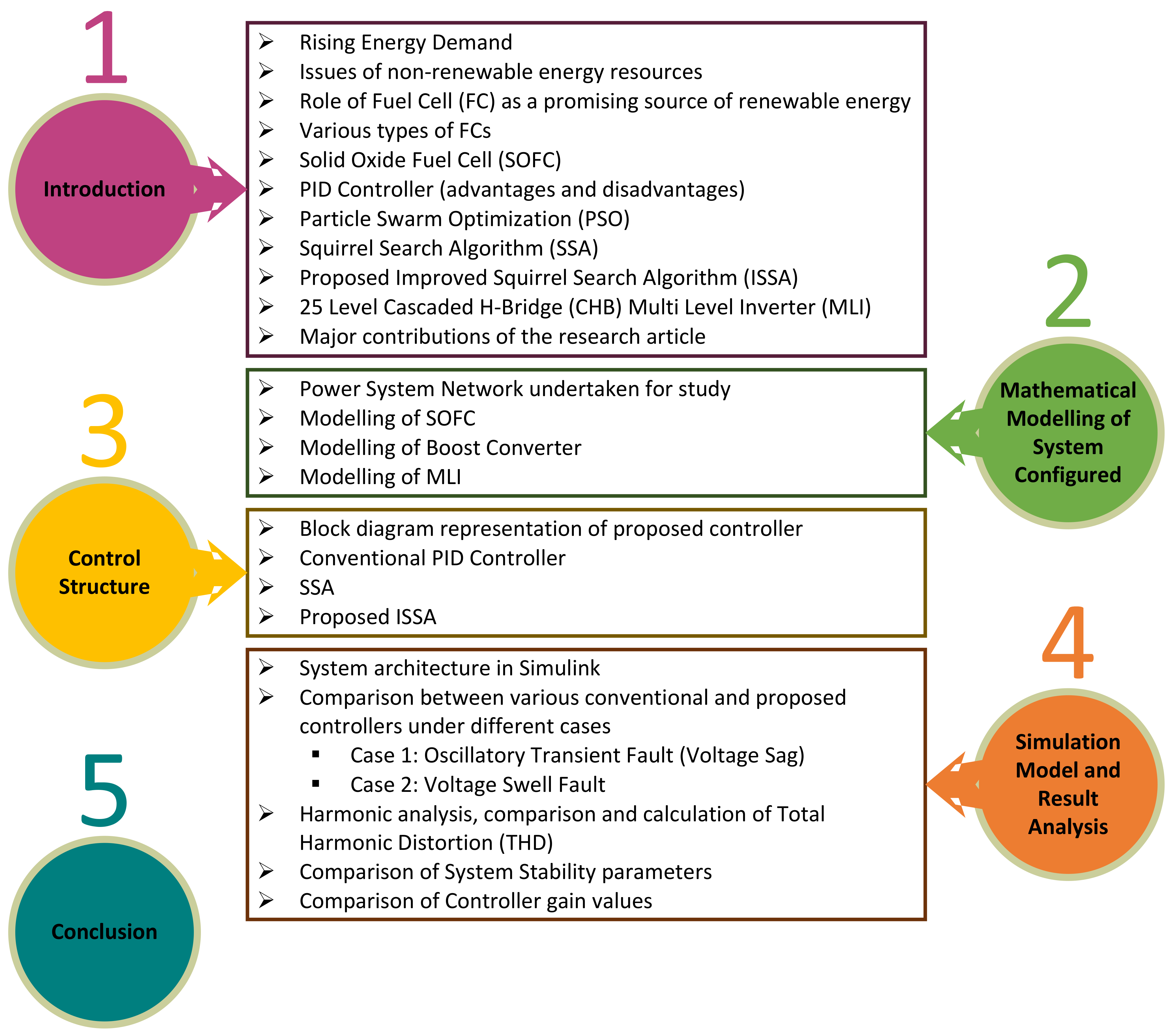
:1. Introduction
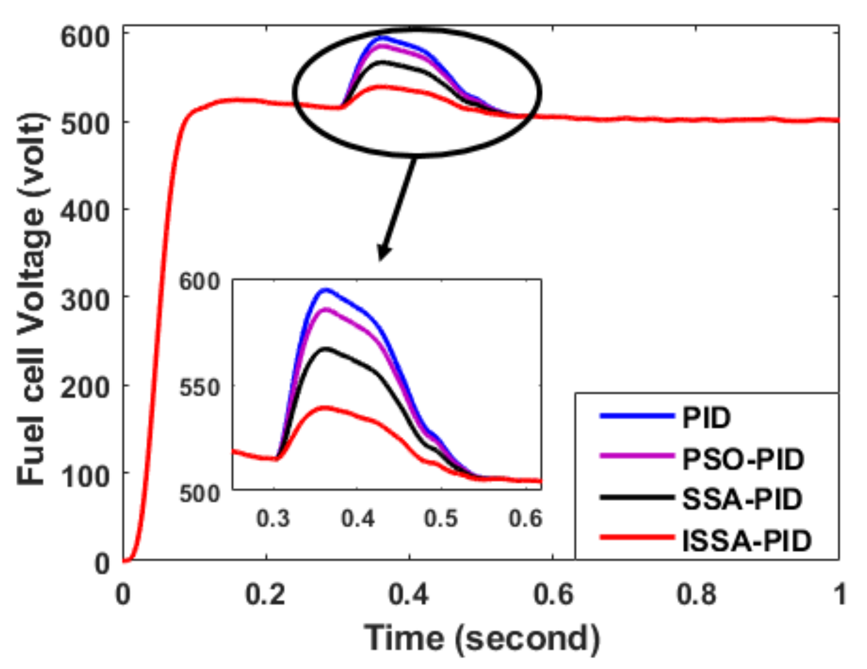
- Recent evolutionary computational techniques (PSO and SSA) are applied for tuning the PID control parameters for dynamic operation.
- Design of an improved evolutionary computational technique (ISSA) for faster convergence speed and better precision.
- The testing of system power quality indices by calculating THD of the conventional and proposed technique.
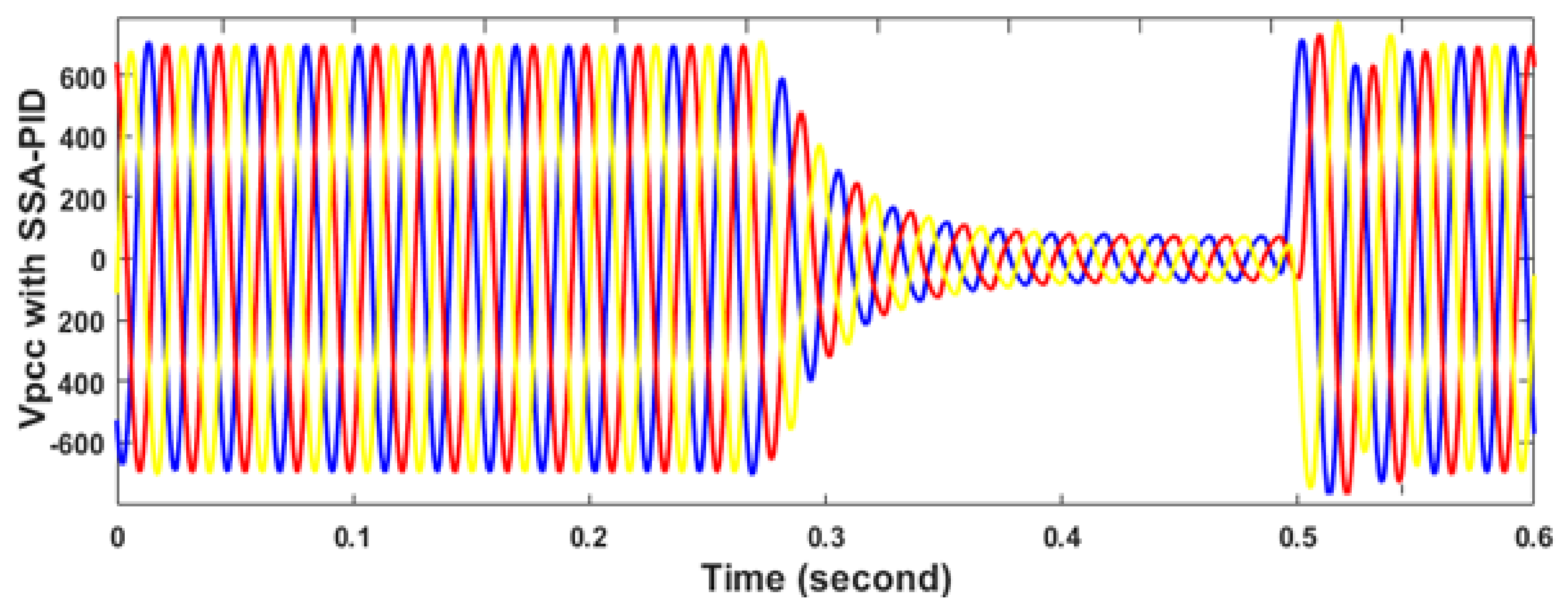
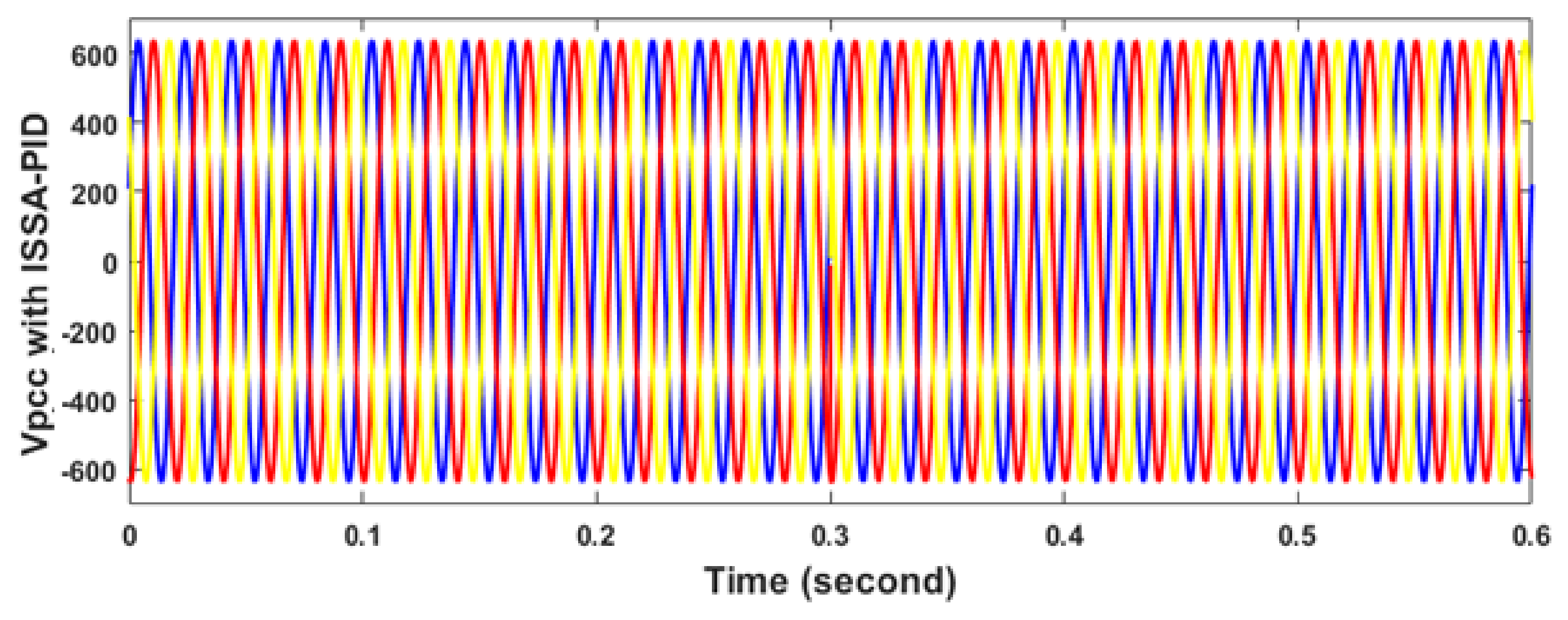
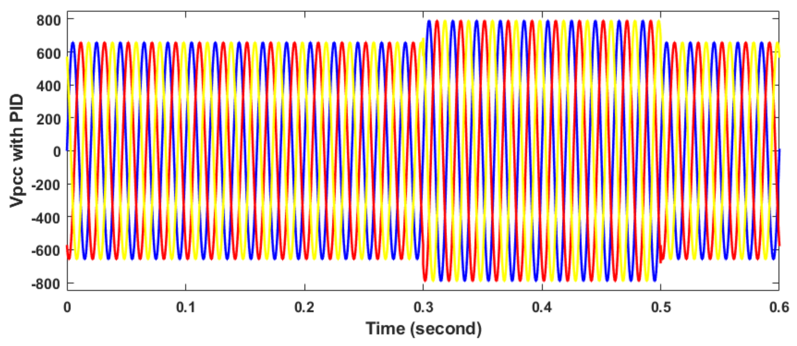
- Study of power quality improvement and the dynamic response subjected to swell and sag conditions for the proposed ISSA technique.
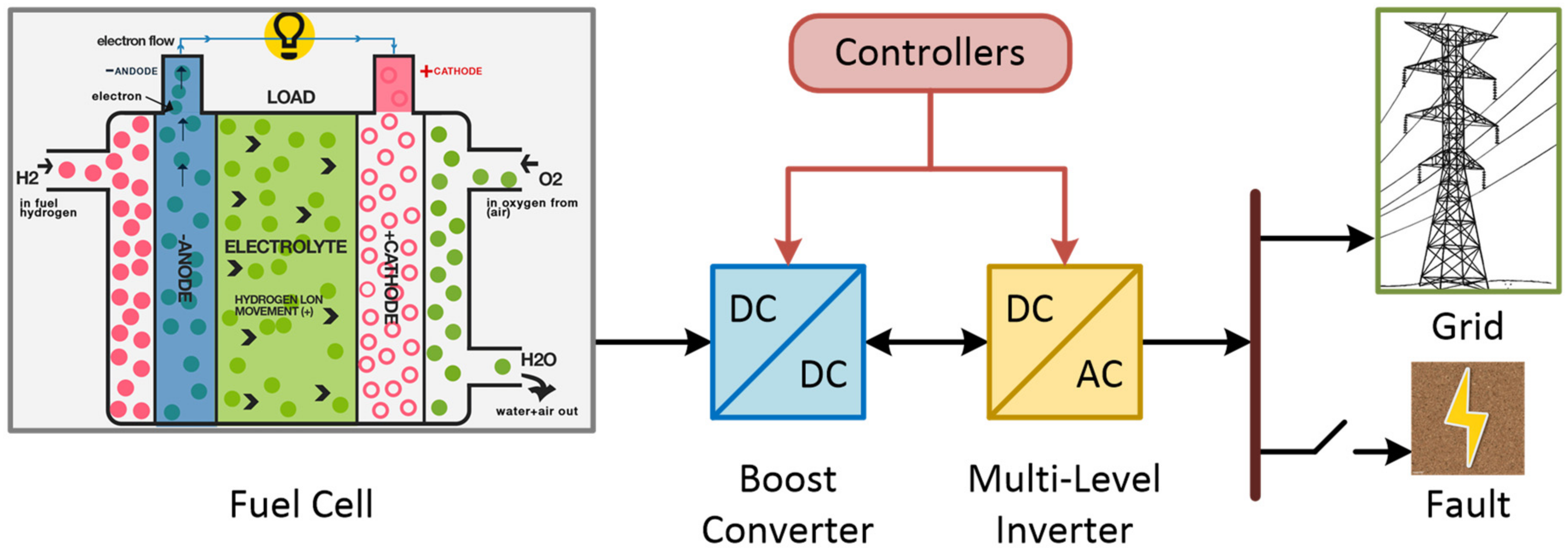
- Use of Solid Oxide Fuel Cell as a distributed generation unit.
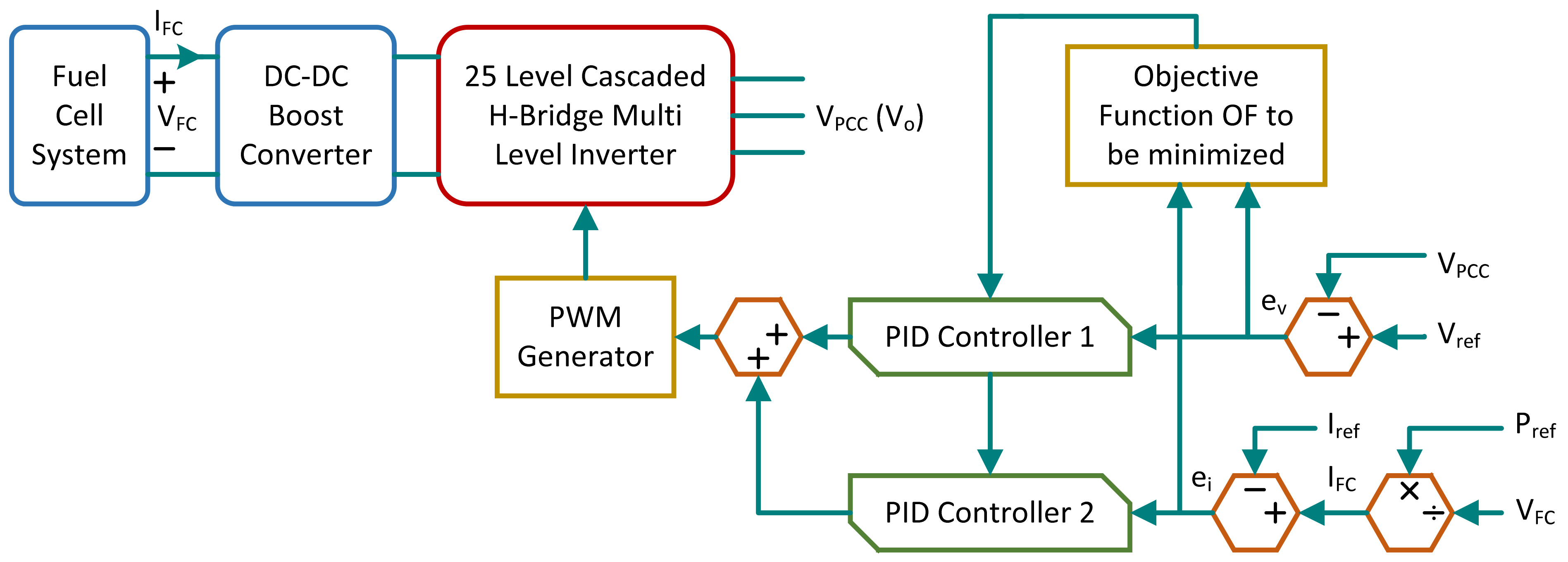
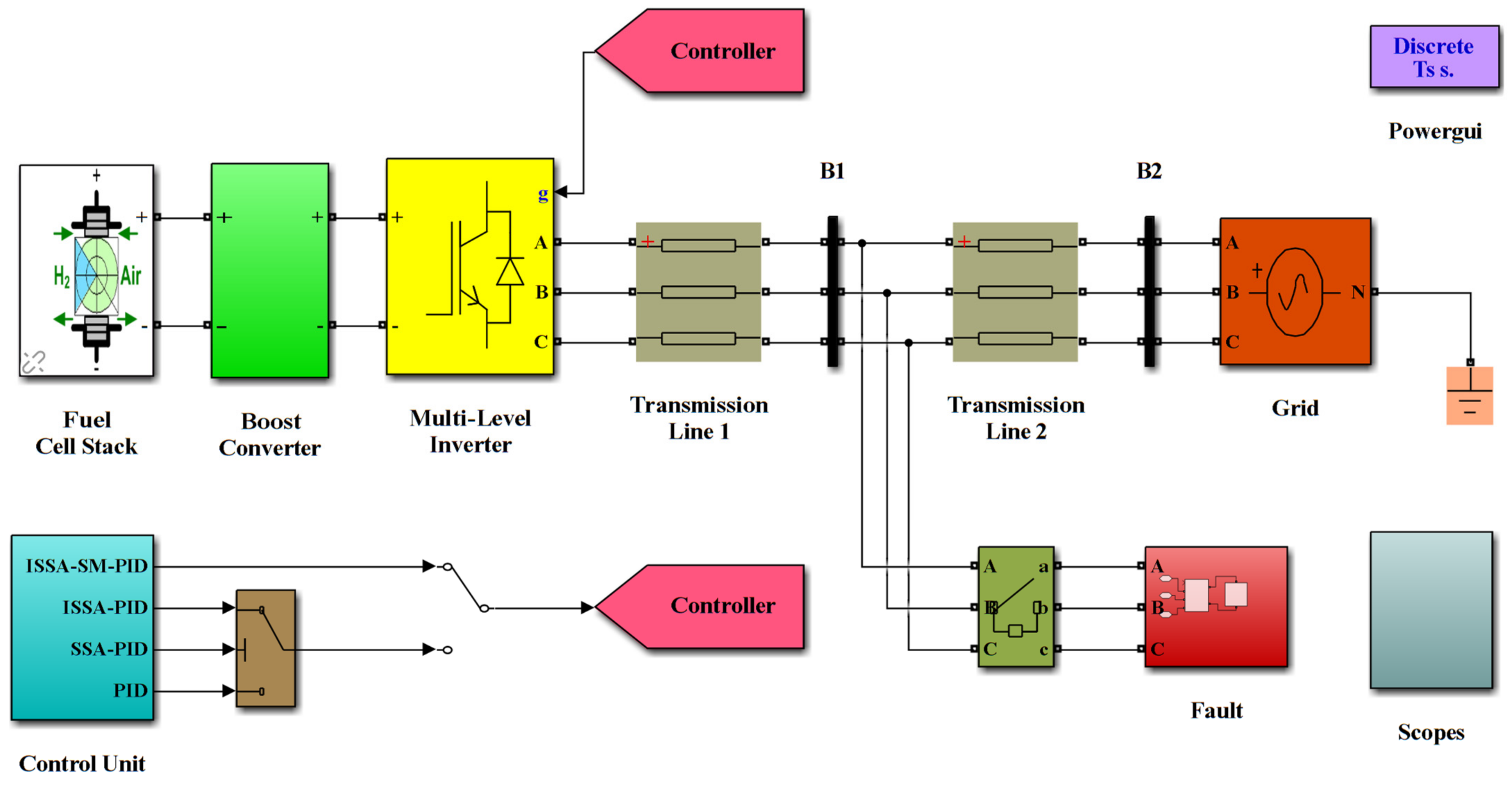
- Two PID controllers are designed to regulate the terminal voltage of the PCC between the SOFC and the power grid by the pulse width modulation (PWM) technique driving the 25 level CHB MLI.
2. Materials
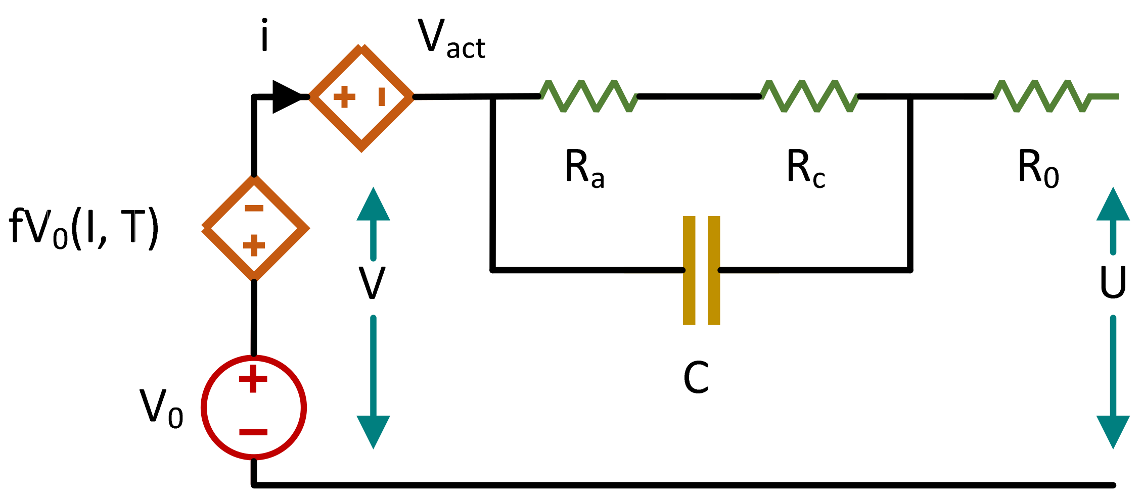
2.1. SOFC Modelling
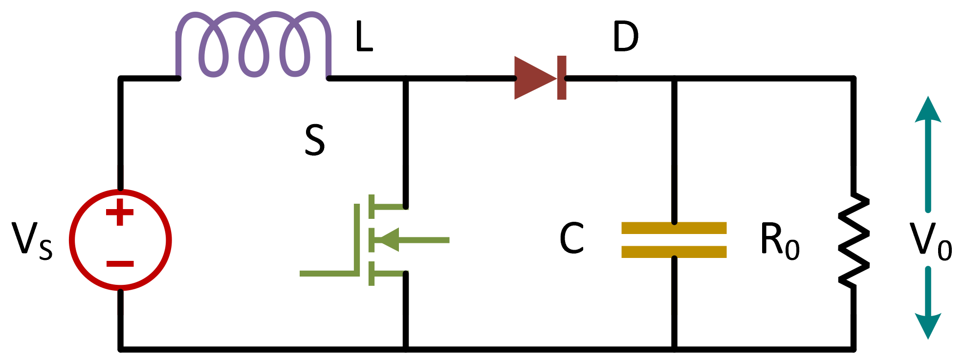
2.2. Modelling of Boost Converter
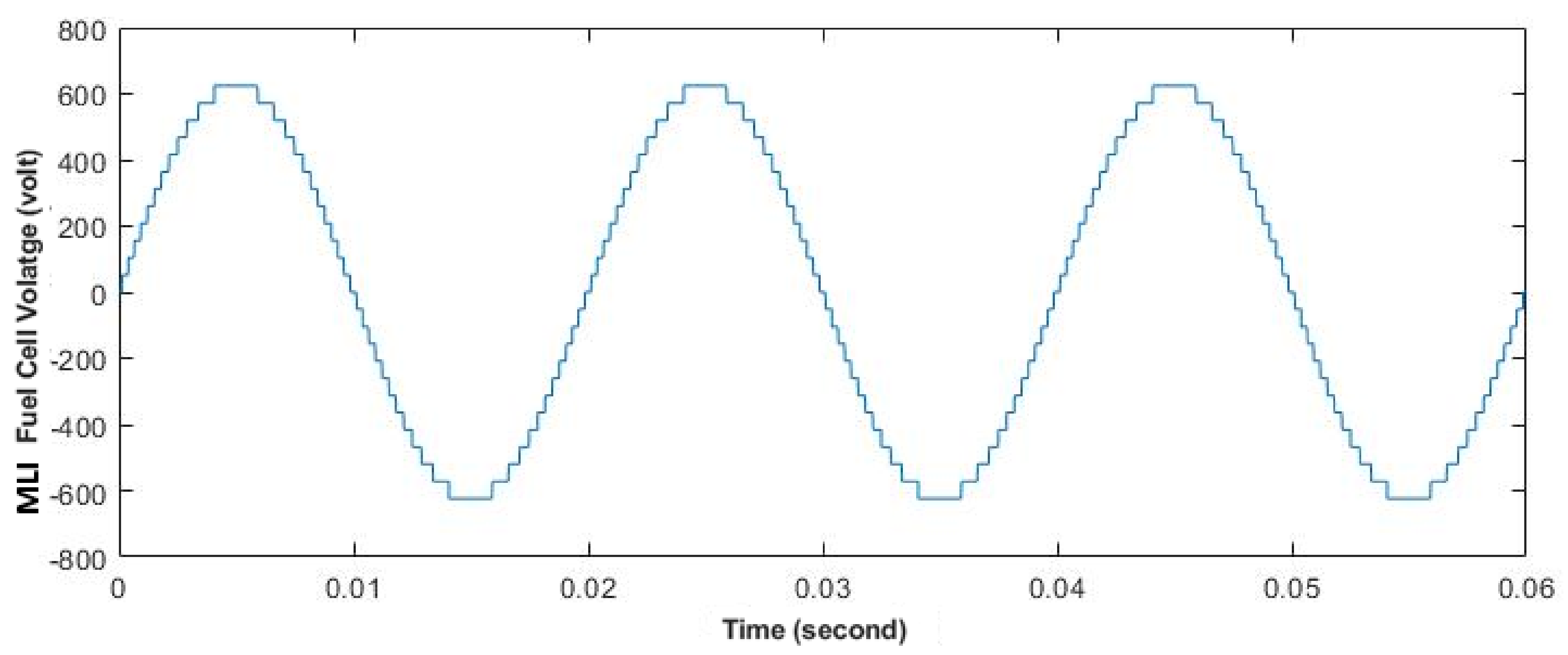
2.3. Modelling of Multi-Level Inverter (MLI)
3. Methods
3.1. Conventional PID Controller
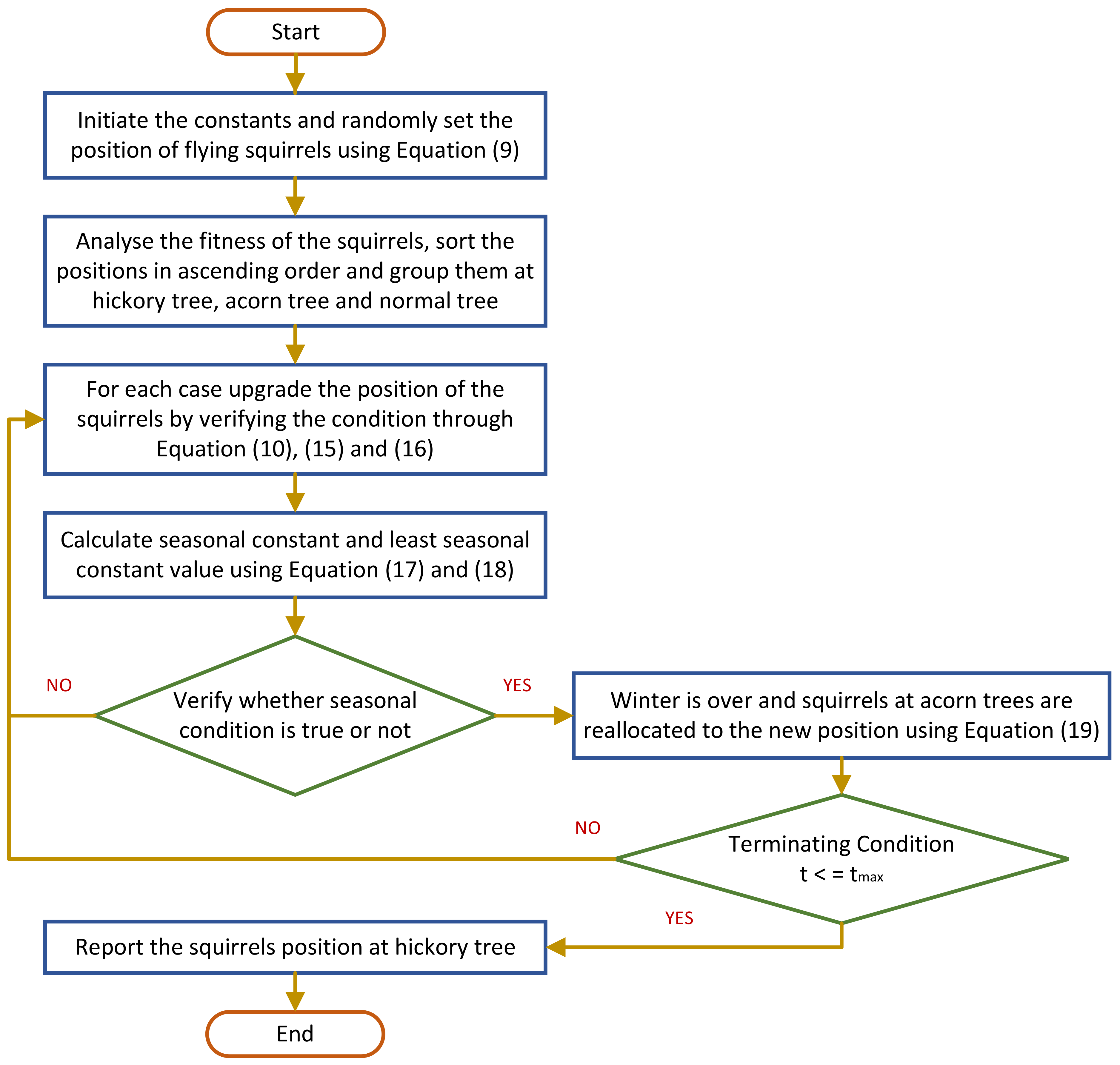
3.2. Squirrel Search Algorithm (SSA)
- There is number of flying squirrels, and each squirrel is to be present on each tree.
- There are three types of trees: a hickory tree, a normal tree, and an oak tree, in which there is a single hickory tree and a triplet of oak trees.
- All flying squirrels seek food sources and desirably use them [22].
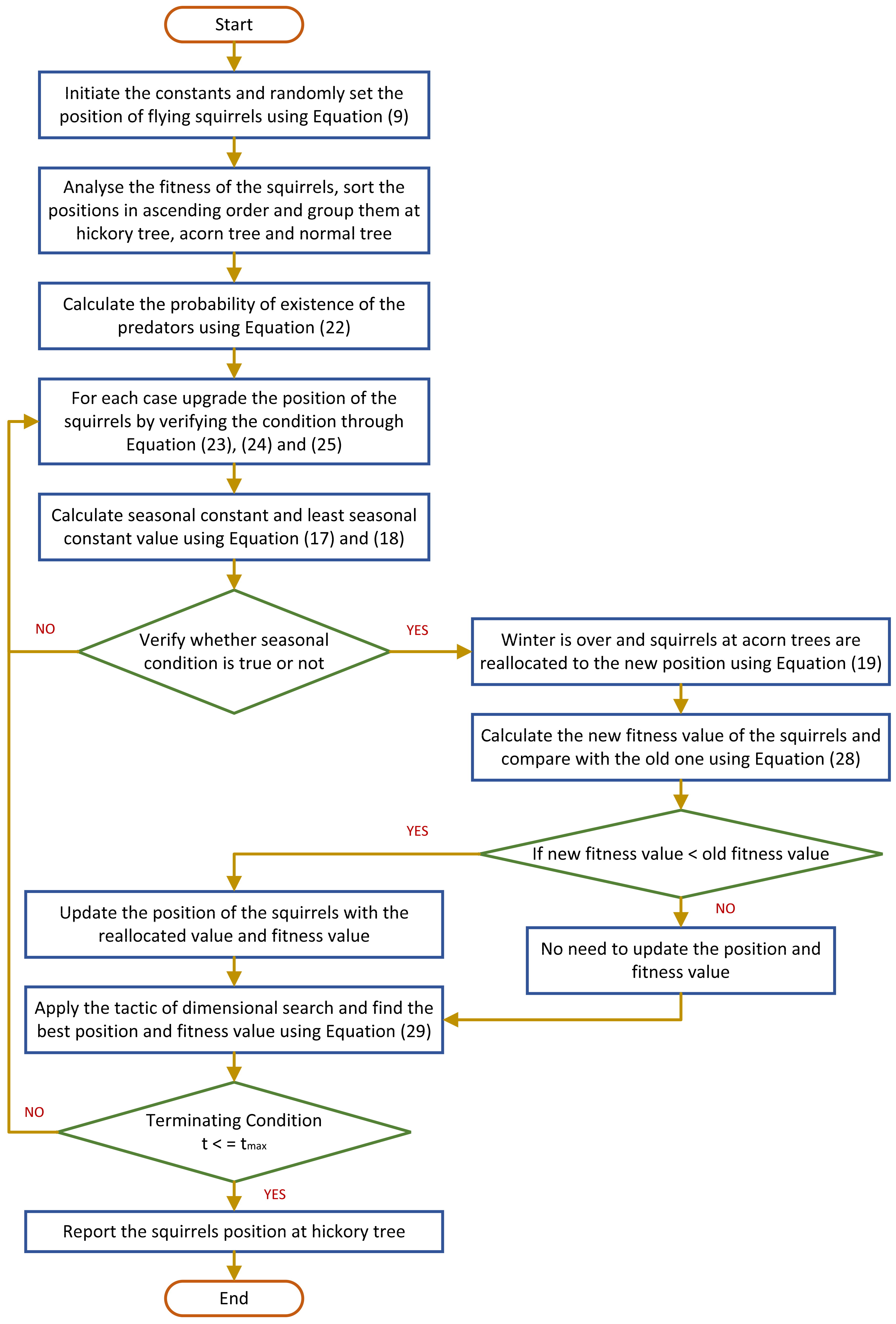
3.3. Proposed Improved Squirrel Search Algorithm (ISSA)
4. Results and Discussions
5. Conclusions
- The system can be operated with new reduced switch MLIs for better efficiency.
- Energy storage units can be added to the system undertaken to compensate for the power delivered by the SOFC during extremities.
- A new optimization technique with a better convergence speed can be implemented.
- Multiple distributed generation systems such as solar, wind, biomass can be incorporated with SOFC to enhance power delivering capacity.
- The system can be tested for other faulted conditions for justifying the performance of the proposed controller.
Author Contributions
Funding
Institutional Review Board Statement
Informed Consent Statement
Data Availability Statement
Conflicts of Interest
Abbreviation
| Abbreviations | Definitions |
| FC | Fuel Cell |
| CHB | Cascaded H-Bridge |
| MLI | Multi-Level Inverter |
| PCC | Point of Common Coupling |
| PSO | Particle Swarm Optimization |
| SSA | Squirrel Search Algorithm |
| ISSA | Improved Squirrel Search Algorithm |
| THD | Total Harmonic Distortion |
| SOFC | Solid Oxide Fuel Cell |
| PSO | Particle Swarm Optimization |
| PEMFC | Polymer Electrolyte Membrane Fuel Cell |
| PWM | Pulse Width Modulation |
| AFC | Alkaline Fuel Cell |
| PAFC | Phosphoric Acid Fuel Cell |
| PEMFC | Proton Exchange Membrane Fuel Cell |
| MCFC | Molten Carbonate Fuel Cell |
| D-C | Diode Clamped |
| F-C | Flying Capacitor |
| ISE | Integral Square Error |
| ITAE | Integral Time Absolute Error |
Appendix A

| System Components | Values |
| FC | Vo = 60, R1 + R2 = 1.4 Ω, R3 = 1.06, C = 1.25 F |
| Boost | L = 0.5 mH, C = 100 µF, Fs = 20 KHz, V0 = 500, Vin = 60 V |
| MLI | IGBTs = 14, Gate Driver Circuit = 11 VOUT = 500 V |
| Transmission Line Parameters | Resistance = 0.01755 Ω, Inductance = 0.8737 × 10⁻³ H, Capacitance = 13.33 × 10⁻⁹ F |
| Grid | V = 600, X/R = 9, F = 50 Hz |
| Fault type | Values |
| Oscillatory Transient | Capacitance = 2000 × 10−6 F, F = 40 HZ |
| Swell | Resistive Load = 1000 Ω, Capacitance = 2500 × 10−6 F, Inductance = 5 × 10⁻³ H |
References
- Mottaghizadeh, P.; Fardadi, M.; Jabbari, F.; Brouwer, J. Thermal Management of Dynamic Operation of Solid Oxide Cell-Based Energy Storage System for 2 Renewable Electricity Scenarios. ECS Meet. Abstr. 2019, 2187. [Google Scholar] [CrossRef]
- Akinyele, D.; Olabode, E.; Amole, A. Review of Fuel Cell Technologies and Applications for Sustainable Microgrid Systems. Inventions 2020, 5, 42. [Google Scholar] [CrossRef]
- Shabri, H.A.; Othman, M.H.D.; Mohamed, M.A.; Kurniawan, T.A.; Jamil, S.M. Recent progress in metal-ceramic anode of solid oxide fuel cell for direct hydrocarbon fuel utilization: A review. Fuel Process. Technol. 2021, 212, 106626. [Google Scholar] [CrossRef]
- Sazali, N.; Salleh, W.N.W.; Jamaludin, A.S.; Razali, M.N.M. New Perspectives on Fuel Cell Technology: A Brief Review. Membranes 2020, 10, 99. [Google Scholar] [CrossRef]
- Bansal, H.O.; Sharma, R.; Shreeraman, P.R. PID controller tuning techniques: A review. J. Control. Eng. Technol. 2012, 2, 168–176. [Google Scholar]
- Chopra, V.; Singla, S.K.; Dewan, L. Comparative analysis of tuning a PID controller using intelligent methods. ACTA Polytech. Hung. 2014, 11, 235–249. [Google Scholar]
- Solihin, M.I.; Tack, L.F.; Kean, M.L. Tuning of PID controller using particle swarm optimization (PSO). In Proceedings of the International Conference on Advanced Science, Engineering and Information Technology, Bangi-Putrajaya, Malaysia, 14–15 January 2011. [Google Scholar]
- Fares, D.; Fathi, M.; Shams, I.; Mekhilef, S. A novel global MPPT technique based on squirrel search algorithm for PV module under partial shading conditions. Energy Convers. Manag. 2021, 230, 113773. [Google Scholar] [CrossRef]
- Zheng, T.; Luo, W. An Improved Squirrel Search Algorithm for Optimization. Complexity 2019, 2019, 6291968. [Google Scholar] [CrossRef]
- Choudhury, S.; Bajaj, M.; Dash, T.; Kamel, S.; Jurado, F. Multi-level Inverter: A Survey on Classical and Advanced Topologies, Control Schemes, Applications to Power System and Future Prospects. Energies 2021, 14, 5773. [Google Scholar] [CrossRef]
- Ray, S.; Gupta, N.; Gupta, R.A. Power quality improvement using multi-level inverter-based active filter for medium-voltage high-power distribution system: A comprehensive review. Int. J. Power Electron. 2021, 14, 1–36. [Google Scholar] [CrossRef]
- Choudhury, S.; Sen, B.; Kumar, S.; Sahani, S.; Pattnaik, A.; Dash, T. Improvement of Performance and Quality of Power in Grid Tied SOFC through Crow Search Optimization Technique. In Proceedings of the 2020 5th International Conference on Communication and Electronics Systems (ICCES), Coimbatore, India, 10–12 June 2020; pp. 68–73. [Google Scholar]
- Damo, U.M.; Ferrari, M.; Turan, A.; Massardo, A. Solid oxide fuel cell hybrid system: A detailed review of an environmentally clean and efficient source of energy. Energy 2019, 168, 235–246. [Google Scholar] [CrossRef] [Green Version]
- Hu, X.; Ma, P.; Wang, J.; Tan, G. A Hybrid Cascaded DC–DC Boost Converter with Ripple Reduction and Large Conversion Ratio. IEEE J. Emerg. Sel. Top. Power Electron. 2020, 8, 761–770. [Google Scholar] [CrossRef]
- Mondol, M.H.; Tür, M.R.; Biswas, S.P.; Hosain, M.K.; Shuvo, S.; Hossain, E. Compact three phase multi-level inverter for low and medium power photovoltaic systems. IEEE Access 2020, 8, 60824–60837. [Google Scholar] [CrossRef]
- Pawar, N.; Tayal, V.K.; Choudekar, P. Design of Cascaded H-Bridge Multilevel Inverter. In Advances in Smart Communication and Imaging Systems. Lecture Notes in Electrical Engineering; Agrawal, R., Kishore, S.C., Goyal, A., Eds.; Springer: Singapore, 2021; Volume 721, pp. 645–655. [Google Scholar] [CrossRef]
- Abd Halim, W.; Ganeson, S.; Azri, M.; Azam, T.T. Review of multi-level inverter topologies and its applications. J. Telecommun. Electron. Comput. Eng. 2016, 8, 51–56. [Google Scholar]
- Siahbalaee, J.; Sanaie, N. Comparison of conventional and new cascaded multi-level inverter topologies based on novel indices. ISA Trans. 2022, 119, 41–51. [Google Scholar] [CrossRef]
- Khodabakhshian, A.; Hooshmand., R. A new PID controller design for automatic generation control of hydro power systems. Int. J. Electr. Power Energy Syst. 2010, 32, 375–382. [Google Scholar] [CrossRef]
- Choudhury, S.; Khandelwal, N. A Novel Weighted Superposition Attraction Algorithm-based Optimization Approach for State of Charge and Power Management of an Islanded System with Battery and SuperCapacitor-based Hybrid Energy Storage System. IETE J. Res. 2020, 1–14. [Google Scholar] [CrossRef]
- Ponnuvel, S.V.; Murugesan, S.; Duraisamy, S.P. Multi-objective squirrel search algorithm to solve economic environmental power dispatch problems. Int. Trans. Electr. Energy Syst. 2020, 30, e12635. [Google Scholar] [CrossRef]
- Jain, M.; Singh, V.; Rani, A. A novel nature-inspired algorithm for optimization: Squirrel search algorithm. Swarm Evol. Comput. 2019, 44, 148–175. [Google Scholar] [CrossRef]
- Sakthivel, V.P.; Suman, M.; Sathya, P.D. Combined economic and emission power dispatch problems through multi-objective squirrel search algorithm. Appl. Soft Comput. 2021, 100, 106950. [Google Scholar] [CrossRef]
- Wang, Y.; Du, T. An Improved Squirrel Search Algorithm for Global Function Optimization. Algorithms 2019, 12, 80. [Google Scholar] [CrossRef] [Green Version]
- El-Ashmawi, W.H.; Elminaam, D.S.A. A modified squirrel search algorithm based on improved best fit heuristic and operator strategy for bin packing problem. Appl. Soft Comput. 2019, 82, 105565. [Google Scholar] [CrossRef]
- Zhang, X.; Zhao, K.; Wang, L.; Wang, Y.; Niu, Y. An Improved Squirrel Search Algorithm With Reproductive Behavior. IEEE Access 2020, 8, 101118–101132. [Google Scholar] [CrossRef]


| Cases | Type of Controllers | Types of Inverter | |||
|---|---|---|---|---|---|
| Multi-Level Inverter | Classical Inverter | ||||
| Control Parameters | |||||
| VFC | VPCC | VFC | VPCC | ||
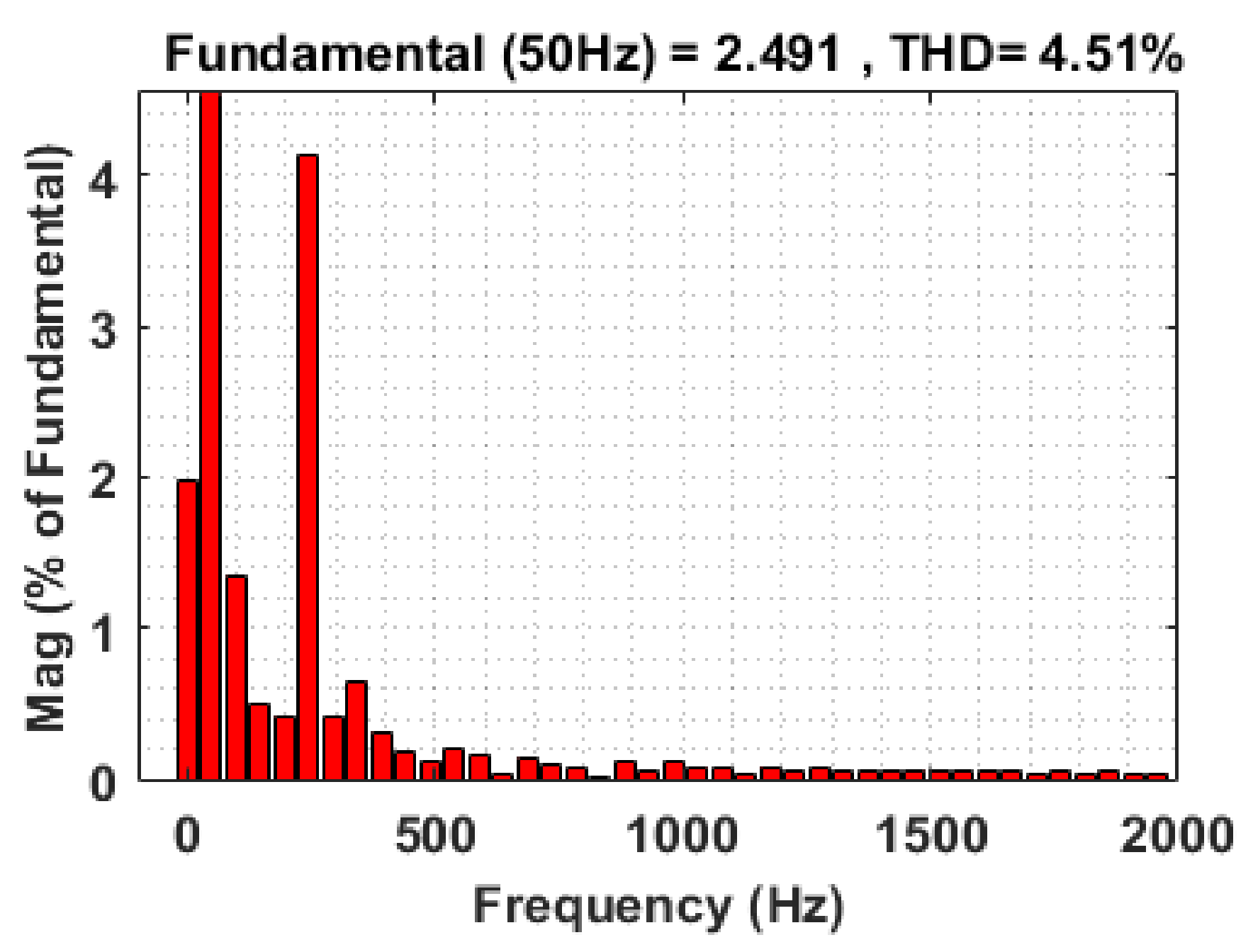
| 1 | Proposed ISSA Based PID | 0.71 | 0.95 | 4.51 | 6.46 |
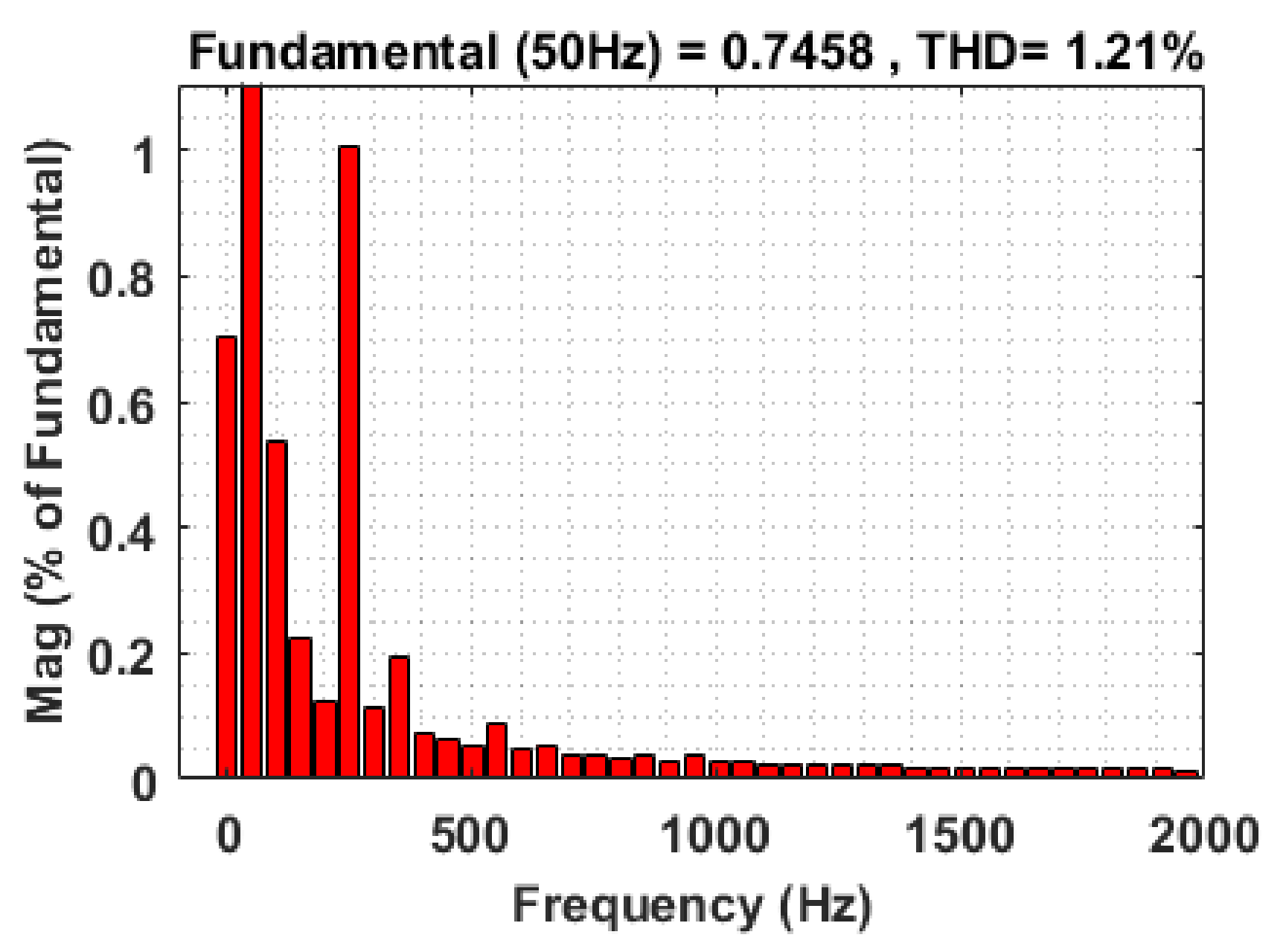
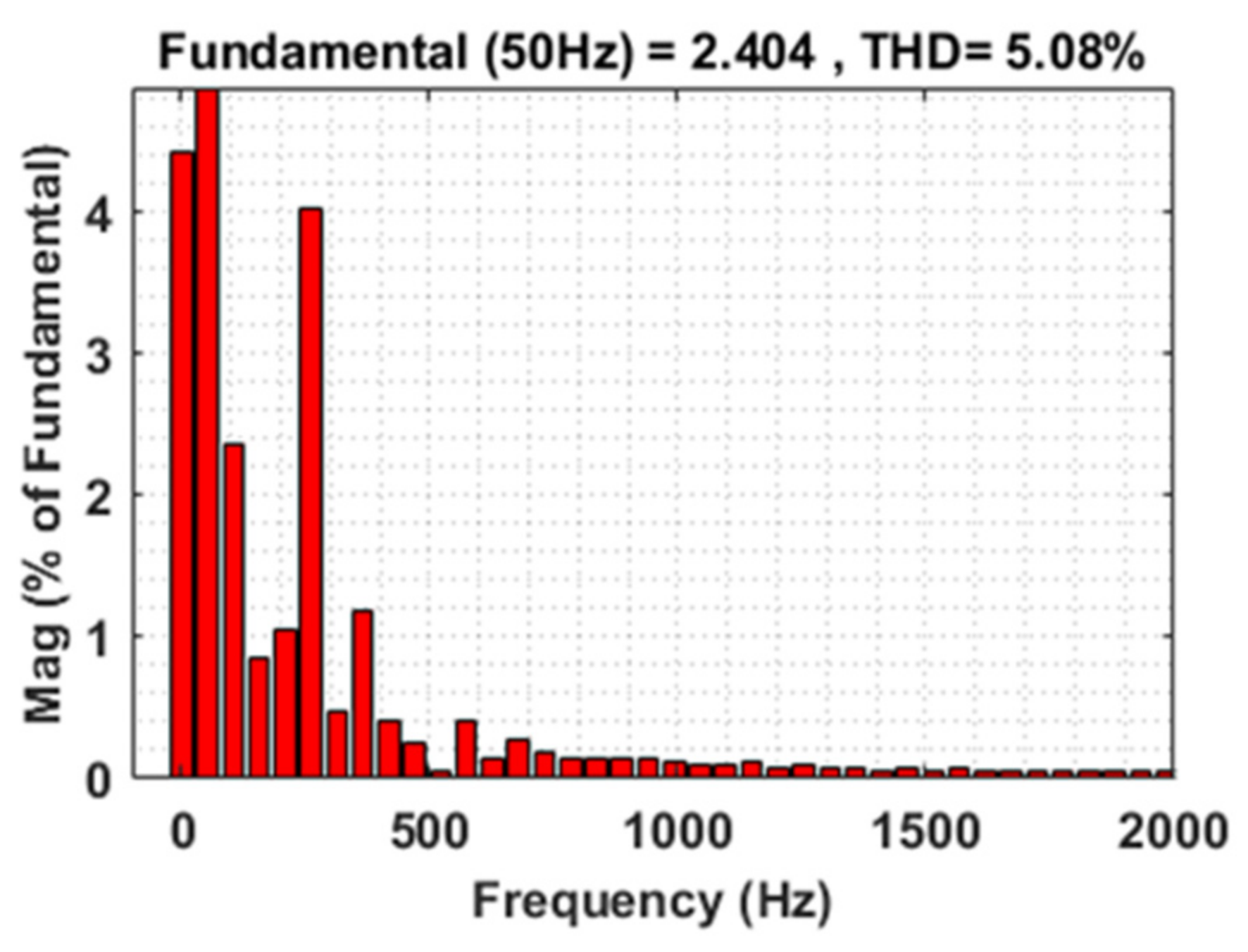
| SSA Based PID | 1.21 | 1.52 | 5.08 | 7.34 | |
| PSO Based PID | 2.23 | 3.14 | 6.54 | 8.41 | |
| Conventional PID | 3.81 | 4.36 | 9.17 | 9.25 | |
| 2 | Proposed ISSA Based PID | 0.83 | 1.0 | 5.82 | 6.69 |
| SSA Based PID | 1.71 | 1.88 | 7.56 | 7.82 | |
| PSO Based PID | 2.79 | 3.22 | 8.81 | 8.99 | |
| Conventional PID | 3.96 | 4.46 | 9.19 | 9.80 | |
| Types of Controller | System Parameters | |||||
|---|---|---|---|---|---|---|
| Voltage of FC | Voltage of Grid | |||||
| Peak Time | Rise Time | Settling Time | Peak Time | Rise Time | Settling Time | |
| ISSA-PID | 1.53 | 1.2 | 1.37 | 2.13 | 1.9 | 1.87 |
| SSA-PID | 2.38 | 2.17 | 2.28 | 3.73 | 2.39 | 2.91 |
| PSO-PID | 3.45 | 2.93 | 2.86 | 4.3 | 3.7 | 3.51 |
| PID | 5.34 | 5.23 | 5.16 | 7.12 | 6.117 | 6.11 |
Controllers Parameters  | ISSA-PID | SSA-PID | PSO-PID | PID | ||||||||
|---|---|---|---|---|---|---|---|---|---|---|---|---|
| Kp | Ki | Kd | Kp | Ki | Kd | Kp | Ki | Kd | Kp | Ki | Kd | |
| FC Voltage | 0.2 | 0.1 | 0.5 | 1.1 | 1.1 | 1.4 | 2.1 | 2.5 | 2.7 | 4.5 | 4.6 | 4.9 |
| GRID Voltage | 0.3 | 0.1 | 0.6 | 1.6 | 1.9 | 1.5 | 2.3 | 3.9 | 3.5 | 5.8 | 5.8 | 6.4 |
Publisher’s Note: MDPI stays neutral with regard to jurisdictional claims in published maps and institutional affiliations. |
© 2021 by the authors. Licensee MDPI, Basel, Switzerland. This article is an open access article distributed under the terms and conditions of the Creative Commons Attribution (CC BY) license (https://creativecommons.org/licenses/by/4.0/).
Share and Cite
Choudhury, S.; Acharya, S.K.; Khadanga, R.K.; Mohanty, S.; Arshad, J.; Ur Rehman, A.; Shafiq, M.; Choi, J.-G. Harmonic Profile Enhancement of Grid Connected Fuel Cell through Cascaded H-Bridge Multi-Level Inverter and Improved Squirrel Search Optimization Technique. Energies 2021, 14, 7947. https://0-doi-org.brum.beds.ac.uk/10.3390/en14237947
Choudhury S, Acharya SK, Khadanga RK, Mohanty S, Arshad J, Ur Rehman A, Shafiq M, Choi J-G. Harmonic Profile Enhancement of Grid Connected Fuel Cell through Cascaded H-Bridge Multi-Level Inverter and Improved Squirrel Search Optimization Technique. Energies. 2021; 14(23):7947. https://0-doi-org.brum.beds.ac.uk/10.3390/en14237947
Chicago/Turabian StyleChoudhury, Subhashree, Shiba Kumar Acharya, Rajendra Kumar Khadanga, Satyajit Mohanty, Jehangir Arshad, Ateeq Ur Rehman, Muhammad Shafiq, and Jin-Ghoo Choi. 2021. "Harmonic Profile Enhancement of Grid Connected Fuel Cell through Cascaded H-Bridge Multi-Level Inverter and Improved Squirrel Search Optimization Technique" Energies 14, no. 23: 7947. https://0-doi-org.brum.beds.ac.uk/10.3390/en14237947