1. General Information
The MARIA reactor is currently the only operating nuclear reactor in Poland. It is operated by the Nuclear Facilities Operation Department at the National Centre for Nuclear Research (NCBJ) located at Świerk Nuclear Centre 30 km outside of Warsaw. The first criticality was achieved in 1974 after 5 years of construction work. The operation horizon is set in the 2050s. Its design was based on the MR research reactor operated by the Kurchatov Institute in Moscow [
1,
2], however, the original design was improved domestically in order to meet specific Polish needs: horizontal neutron beams for scattering experiments, and vertical irradiation positions for radionuclide production were added. The MARIA reactor is a water- and beryllium-moderated, water-cooled, channels-in-pool type reactor. Pressurized fuel channels contain concentric multi-tube fuel element assemblies. The reactor core, submerged in the water pool, has been designed with a high degree of flexibility to provide a wide range of applications. As a multifunctional research facility, MARIA also covers utilizing neutron beams for research on boron neutron capture therapy (BNCT) and irradiation of biological samples, neutron activation analysis, and research for condensed matter physics. An essential part of the MARIA mission is the training of students and nuclear specialists.
The MARIA reactor’s nominal thermal power is 30 MW. Following preparations that started in 2004, the MARIA reactor core underwent conversion from HEU to LEU, which ended in 2014. In the process, we licensed two types of LEU fuel—French MC and Russian MR, both under 20% of uranium enrichment. The National Nuclear Security Administration (NNSA) assisted MARIA’s conversion through its Global Threat Reduction Initiative (GTRI), which aims to reduce and protect vulnerable nuclear and radiological materials located at civilian sites worldwide [
3,
4]. Argonne National Laboratory (ANL) backed NCBJ in evaluation of the feasibility of converting MARIA to operation with LEU fuel, selection of a suitable LEU fuel design and development of a new version of the safety analysis report. ANL assisted NCBJ with the procedure of conversion approval in national regulatory body assessment.
During the conversion process, the need for upgrading and modernization was revealed. Therefore, the reactor was systematically modernized, most important modernizations performed included replacement of main cooling pumps and commissioning of the new residual heat removal pumps, partial replacement of beryllium and graphite blocks, modernization of the power supply system, heat exchangers piping design change, and modernization of experimental facilities on horizontal reactor channels.
2. Description of the MARIA Reactor Core
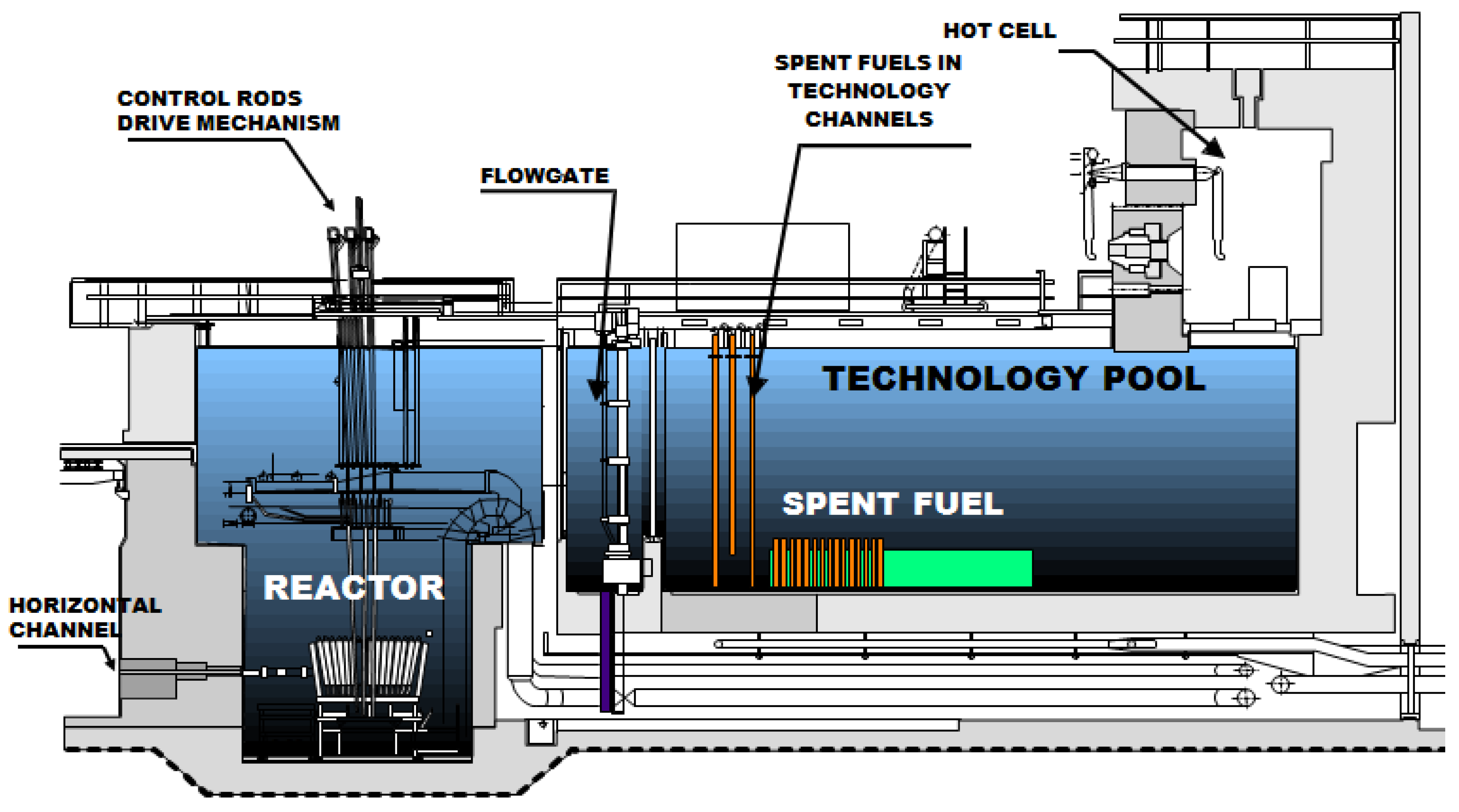
The reactor core is enclosed in the nest structure, which supports its elements: fuel elements in channel tubes, beryllium blocks serving as one of the two moderating substances (together with light water) and graphite blocks reflecting neutrons to the core. Additionally, some of the blocks contain horizontal holes for the extraction of neutron beams from the reflector to the horizontal beam tubes penetrating the reactor biological shield. All of the elements mentioned above are located in the pool containing light water that serves as a coolant and biological shield.
Fuel channels, and graphite and beryllium blocks are conically arranged. This solution makes the reactor core compact and, at the same time, it is easy to load it from the top. The cross-sections of the reactor are shown in
Figure 1. A detailed description is presented in the following sections of the article (and also can be found in [
5]).
The reactor core design includes the modularity of the structures including beryllium and graphite blocks, plugs and channels. This feature provides a possibility to adjust the reactor core to the stakeholders’ requirements and enables tailoring use of neutrons. Schematic diagram of the exemplary core layout is shown in
Figure 2.
2.1. Fuel Elements
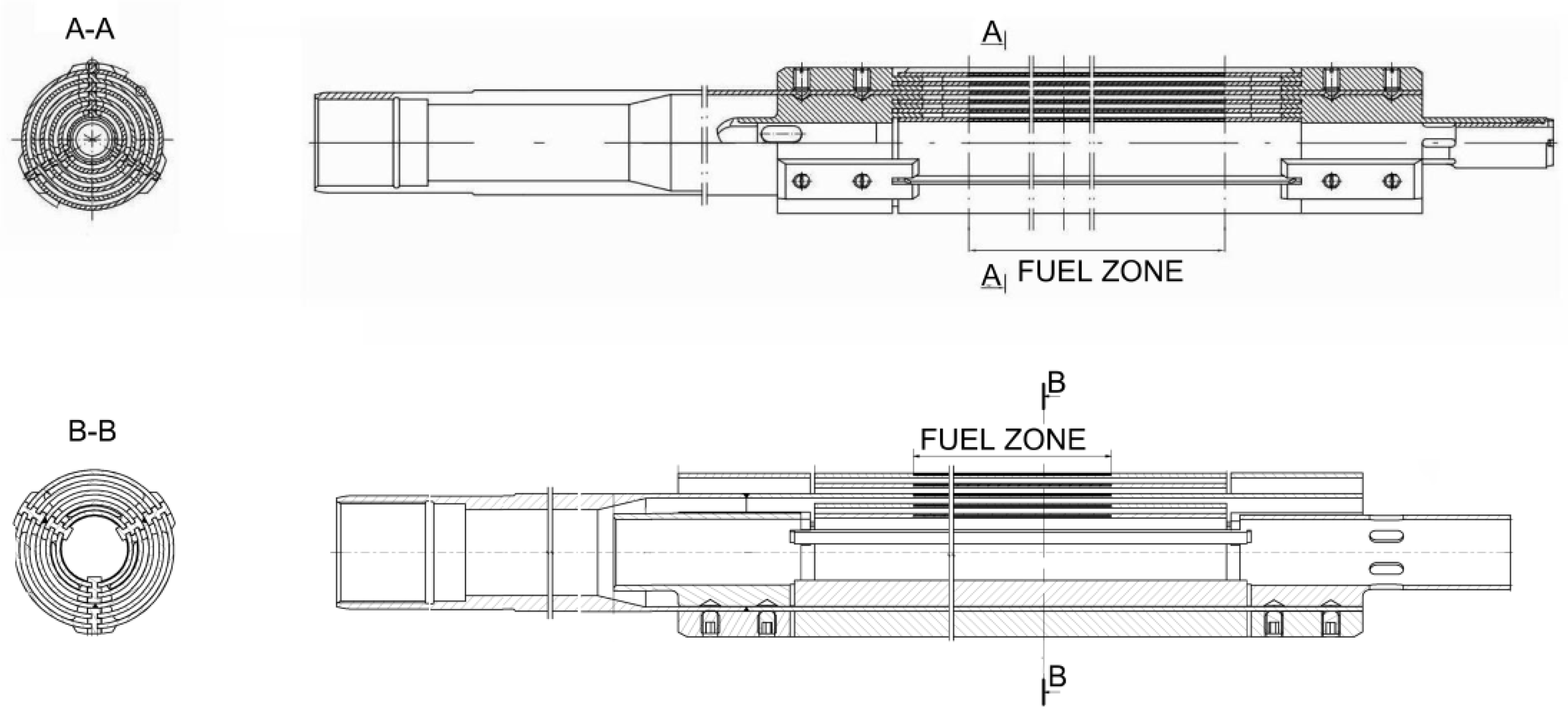
Since 2015, when the reactor was fully converted to LEU fuel, two types of fuel elements have been utilized. The MC-5 fuel element, is manufactured by France and the MR-6 fuel element is designed and delivered by the Russian Federation. The fuel assembly contains five (MC-5) or six concentric (MR-6) tubes with uranium enriched to: 19.75% and 19.7% of
235U, respectively. The MC-5 fuel meat utilize uranium silicide (U
3Si
2). The MR-6 fuel is manufactured as uranium oxide (UO
2) dispersed in aluminium matrix. Each fuel element tube is cladded in 2 mm of aluminium sheath. Active length of the fuel, for both types, is 1 m. Schematic drawings of both types of fuel are presented in
Figure 3.
Fuel assemblies are placed in the pressurized channels and are individually connected to the primary cooling circuit. Typically cycle-to-cycle core configuration is changed due to the fuel burnup and current irradiation requirements. For example, irradiation of uranium plates inside rigs for 99Mo production requires the replacement of two fuel assemblies.
2.2. Moderator
The main moderating element in the core is water, which also provides cooling of fuel channels and core materials. Its volumetric fraction in the core is only 20%, but it contributes to neutrons slowing up to 70%. The remaining 30% of neutron moderation occurs in beryllium, constituting the core matrix and filling up the space between the fuel channels. Due to its better nuclear properties, beryllium enables expanding the lattice pitch creating space for large loop experiments.
2.3. Reflector
The reflector consists of graphite blocks canned in aluminium and cooled by the pool cooling water flowing in the separate pool cooling circuit. Besides the basic graphite blocks, the reflector contains multiple square blocks with beam holes forming the extensions of horizontal beam tubes and aluminium blocks filling the reflector space around the horizontal channel passages.
2.4. Reactor Cooling System
The MARIA reactor is equipped with two individual primary cooling systems. It helps to provide safe operation and allows operation of special in-core facilities which can be connected to the main cooling system. MARIA’s primary cooling system consists of two circuits:
The fuel channel cooling circuit consists of the main loop and residual heat removal loop jointly attached to pressure stabilizer. During normal operation, two main pumps are operational with two residual heat removal pumps operating in by-pass loop. The schematic drawing of fuel channel cooling circuit is presented in
Figure 4.
The reactor pool cooling circuit removes heat generated in beryllium matrix, in graphite reflector and reactor pool water. The water flowing down through the core is sucked into a chamber underneath, flows through the collector in the installation duct and is directed through a gauze filter to the circulating pumps, after which it passes through the heat exchangers and again into the reactor pool.
2.5. Reactor Shielding
The upper reactor shielding is provided by 7 m of pool water above the core. It also provides shielding against gamma radiation from secondary radiation sources, such as headers and connecting pipes of the primary cooling circuits and the pipes of test loops filled with activated coolants.
The lateral shielding comprises graphite reflector and pool water, but its main element is a wall of heavy concrete, 2.2 m thick at the core level. Inside, steel wall is adjacent to concrete wall of the reactor pool, while its outside shape is an irregular polygon. The reactor side shield reduces the radiation levels to low dose rate values enabling the work in the experimental hall.
A summary of the main parameters of the MARIA research reactor is presented in
Table 1.
3. Irradiation, Experimental and Testing Facilities in MARIA Reactor
The MARIA research reactor offers an opportunity to use several production and experimental devices at once, inter alia:
vertical channels for radionuclide production;
thermostatic irradiation rigs for material testing and reactor fuel studies, horizontal experimental channels for neutron beam studies;
possibility of using pressurized fuel channels for radionuclide production and advanced nuclear technology research.
The neutron irradiation services provided at the MARIA research reactor include a wide range of radionuclide production, neutron activation analyses and biomedical technology. Today, nuclear reactors remain a key component in the production of the nuclides mainly for use in nuclear medicine diagnostics and therapy. Available services cover the activation of a large spectrum of target materials for the production of nuclides, which can be processed at the discretion of the customers. The irradiation services are performed in various facilities installed in MARIA, depending on the required neutron flux levels, irradiation period, targets mass and their geometry. MARIA design allows installation of various types of irradiation facilities and neutron sources corresponding with the neutron flux performance 2 × 10
14 n/cm
2 s in the case of thermal neutrons and 3 × 10
13 n/cm
2 s in the case of fast neutrons. The neutron flux density assumes a cosine distribution [
6], and its value depends on the location in relation to the fuel channels.
3.1. Infrastructure for Radionuclide Production
In the reactor core and reflector area there are a number of vertical irradiation channels, mainly used for radionuclide production but also which can be used for research involving irradiation.
Various target materials are irradiated in the channels. The one of most bulk is tellurium dioxide. Annually more than 2000 containers containing almost 200 kg of tellurium dioxide are irradiated. This results in over 1 PBq of 131I annual production. Recently, the tellurium dioxide enriched in 130Te has been introduced to irradiation. This greatly increases the efficiency of 131I production.
The unique infrastructure with two hot cells enables the handling of the irradiated targets. The first hot cell is a facility with a shielding wall securing operation with materials up to 3.7 × 10
13 Bq of
60Co activity The second one with 3.7 × 10
12 Bq of
60Co activity. The cans with the radionuclides are transported with a loading machine reaching into the cells through curvilinear channels. Below the cells there is a transport corridor for inter-cell transport and for transport outside the reactor. Besides these two hot cells, the reactor is provided with a hot cell for spent fuel element handling. Heavy shielding allows handling elements with activity equivalent up to 3.7 × 10
15 Bq of fission products.
Figure 5 shows loading outlets of some of the reactor vertical irradiation channels.
3.2. Facility for Irradiation Uranium Targets for 99Mo Production
3.2.1. Production of Fission Product 99Mo Using Uranium Plates
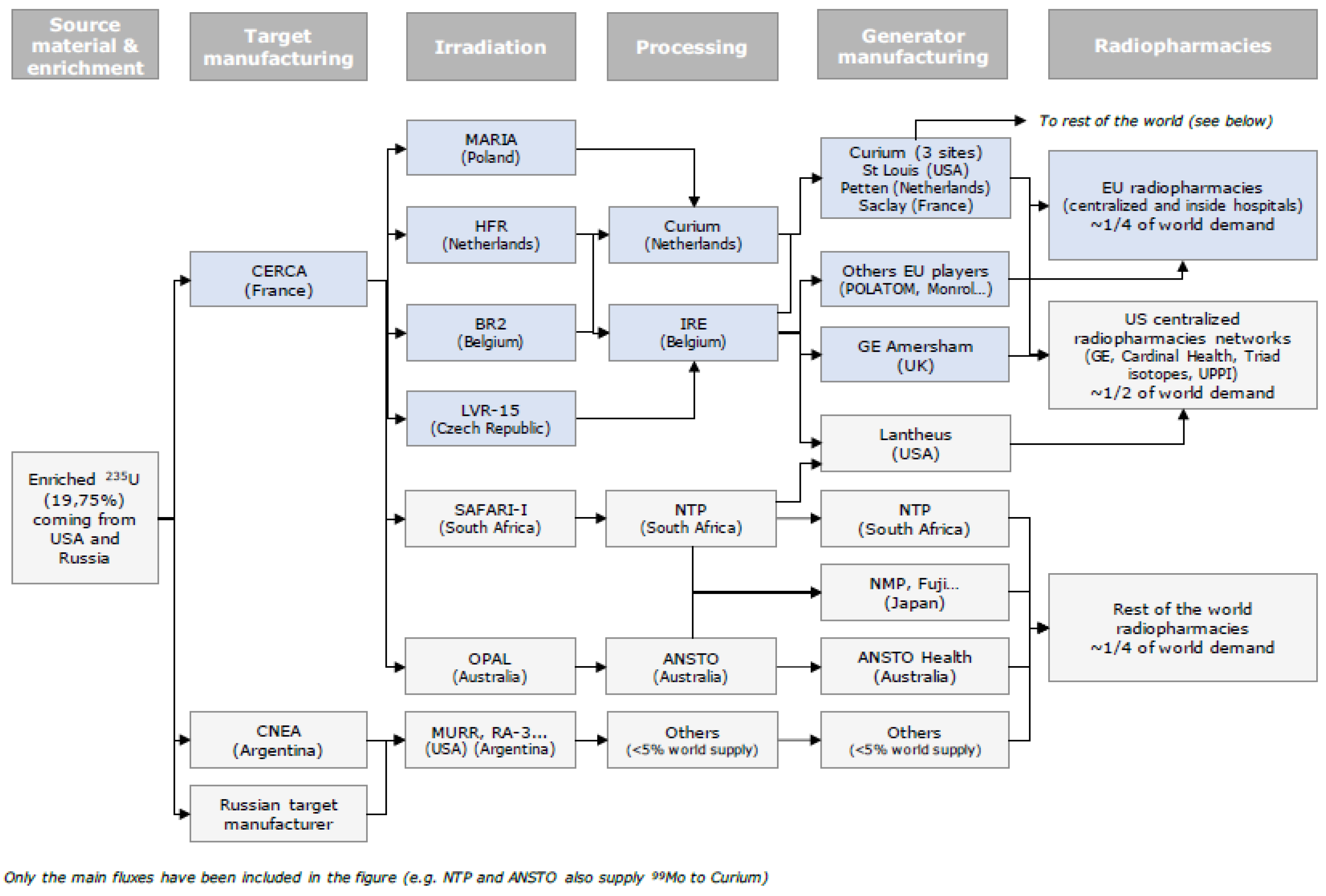
Irradiation of the uranium targets for
99Mo production plays a particular role in utilizing the MARIA reactor. This activity supports the global chain of research reactors producers of
99Mo. Besides the MARIA reactor, the following European reactors are crucial in the supply of
99Mo: HFR (Petten, The Netherlands), BR2 (Mol, Belgium) and LVR15 (Řež, Czech Republic). Map of
99Mo/
99mTc supply chain is shown in
Figure 6.
Commercial irradiation of uranium targets for
99Mo production has been carried out in the MARIA reactor since 2010 [
8]. According to the order, the targets are irradiated in two or three positions inside the irradiation channel, with four uranium targets placed in one position. During the operational cycle, two of those channels are installed in the core. Following the shortage of the critical medical radioisotope
99Mo and its daughter
99mTc related to long-term reliability, management of MARIA declared readiness to irradiate newly designed LEU targets. Due to the high reliability of the reactor and world pressure to convert to LEU targets, NCBJ decided to start the certification program of the new LEU targets. The program was successfully completed and irradiation of LEU targets has been carried out in the MARIA reactor since December 2017 [
9].
Receiving the 99Mo from the fission products is one of the most effective methods for gaining this isotope. It enables to gain a high specific activity of this isotope in a relatively short time. These features combined makes research reactors a crucial tool to fulfill the supply chain of molybdenum-technetium generators commonly used in oncological diagnostics.
Adaptation of the reactor fuel channel to irradiate uranium plates relies on its modification to provide multiple loading and discharging of the uranium sets with targets into and out of the installation without the necessity of evacuation of the whole irradiation channel from the position socket in the reactor core. After reactor shutdown the construction of the internal channel structure allows the channel head to be removed in order to take out and transport the irradiation container together with the uranium targets below the water, to the hot cells. The technology of uranium target’s irradiation gives the possibility to use the standard reactor channel cooling system to remove the heat from molybdenum channels and the use of all reactor control systems.
3.2.2. Production of Fission Product 99Mo Using LEU Microspheres
The worldwide forecasts set an excellent perspective of using 99Mo in nuclear medicine, which allowed starting with the other program dedicated to 99Mo production. Second technology of 99Mo production is based on the innovative type of targets designed as microspheres with UO2 core. The main advantage of the new technology is minimizing nuclear wastes. As a result of collaboration between the MARIA team and specialists from MURR (Missouri University Research Reactor, located in United States of America) microsphere target were manufactured and special irradiation facility was constructed and manufactured in MARIA.
Three irradiation tests were performed from 2017 to 2019 [
10,
11]. The targets irradiated in the MARIA were transported to the hot cell laboratory in the Radioactive Waste Management Plant (ZUOP, located in the Świerk Nuclear Centre, the same as MARIA reactor, which is a great advantage). The radiochemistry procedure was used in order to separate
99Mo from fission products.
3.3. Experimental Facilities for Fast Neutron Irradiation
The MARIA reactor is equipped with an out-of-core irradiation facility which enables irradiation of large-size (up to 90 mm in diameter) target materials/devices with fast neutron flux density up to 1.7 × 10
12 cm
−2 s
−1 and well reduced thermal neutron flux, limited down to 3.4 × 10
10 cm
−2 s
−1. The facility consists of four assemblies with four irradiation channels each and is used for testing and qualification of various materials, equipment and components [
12,
13]. Another purpose-built ready to use facility is a channel for fast neutron irradiation. The facility comprise a thermal-to-14 MeV neutron converter with
6Li and deuterium compounds. The two-step reactions induced by thermal neutrons are the key working principle of the facility [
14]. Inside the converter 14 MeV neutron flux density of over 1 × 10
9 cm
−2 s
−1 with cut-off thermal neutrons has been achieved. Such working conditions are affected by the reactor core configuration and thus it is possible to mimic the neutron energy spectrum in in thermonuclear devices. The loading capacity of the converter is approximately 60 cm
3 (four containers, Ø15 × 90 mm each). The converter was initially designed for material research, i.e., irradiation tests of new structural materials for generation IV nuclear reactors and fusion facilities [
15,
16]. Nevertheless, it can serve for radiopharmaceuticals production by fast neutrons in threshold reactions.
3.4. Irradiation of Ho-PLLA Microspheres
Irradiation of the Ho-PLLA microspheres is another result of international cooperation between specialists from MARIA and European company. The microspheres containing holmium are used in radioembolization procedures as an innovative form of radiotherapy to treat liver cancer. The preliminary studies show auspicious results, and it could be a valuable treatment method. In radioembolization, small particles known as microspheres are administered in the liver artery. The microspheres lodge in the tumour microvasculature and deposit a targeted dose of radioactivity.
To address the limitations of
90Y therapy, a next-generation radioembolization method has been developed based on
166Ho (T
1/2 = 27 h).
166Ho emits β-particles of energy up to 1.86 MeV, but it emits in addition also primary photons of 80.58 keV. That allows using single-photon-emission computed tomography (SPECT) to determine microspheres distribution and dose applied. In addition holmium is a paramagnetic allowing determination of microspheres distribution also using nuclear magnetic resonance (NMR) imaging [
17]. The microspheres containing holmium are made of biodegradable poly (L-lactic acid)–PLLA. They are approximately 30 μm in diameter. The irradiation process needs to assure precise
166Ho activity (depending on microspheres mass, patient dose, transport time etc.), while maintaining the physical integrity (size, spherical, homogeneity, etc.).
Degradation of PLLA microspheres starts above a temperature of approximately 60 °C. Therefore, the process of irradiation has to take into account the possible overheating of the microspheres [
18]. The temperature of the irradiated target depends on nuclear heat generation in the target, heat transfer. Due to the uncertainties of the aforementioned parameters, the standard irradiation conditions led to unsatisfactory results.
In order to reduce nuclear heating in irradiated Ho-PLLA microspheres the peripheral irradiation channel of the hydraulic rabbit system has been selected to perform the irradiation. Improved water cooling has been applied to the hydraulic rabbit system channels. A purpose-designed irradiation vial for Ho-PLLA microspheres (see
Figure 7) and filling irradiation containers with helium allows for more efficient heat removal from the microspheres during irradiation.
A series of experimental irradiations allowed the irradiation technology to be improved. That led to the successful validation of the MARIA reactor as a supplier of irradiated spheres in July 2017 [
20]. Since then, the Ho-PLLA microspheres irradiated in the MARIA reactor have been supplied to a number of medical centers in Europe for over 100 cancer patient treatment annually [
19].
3.5. Experimental Fuel Assembly MR-2 for Fast Neutron Irradiation
Design of MARIA’s core results in excellent irradiation capabilities in a thermal neutron spectrum with flux up to 2 × 10¹⁴ n/cm2 s, but it limits the fast neutrons flux to 2 × 10¹³ n/cm2 s. In order to broaden the irradiation capabilities in the fast flux new design of the Russian MR-2 fuel assembly with a place for the irradiation target in the centre of the fuel element has been proposed—in order to increase fast flux up to 1 × 10¹⁴ n/cm2 s.
The new MR-2 fuel bears similarity to MR-6 fuel. MR-2 design includes two, instead of six, fuel tubes and an aluminium flow separator. The inner fuel tubes removal created a space for irradiation container with the 34 mm in diameter along the whole active length of the fuel. With the fuel active part length of 1000 mm, the total volume of irradiation is 0.0908 m
3. Additional cadmium shielding is proposed in one of central container variants as a measure to cut-off thermal neutrons from the spectrum. The steady state and transient calculations with the finite volume method were performed, in the latter, loss of coolant accident (LOCA) scenario was assumed. Calculations results concluded that the new MR-2 fuel can be safely utilized in the MARIA reactor [
21].
The MR-2 fuel opens a possibility for new research programs connected to irradiation in fast neutron spectrum including material testing for new generation reactors. The 34 mm container provides a large loading volume for irradiation targets. Two MR-2 fuel elements are already prepared to be commissioned in the MARIA reactor.
3.6. Horizontal Channels
MARIA is equipped with eight horizontal neutron beams (H1 to H8). The neutron beam is streamed through horizontal channels that pass through the biological shield and the reactor pool to the core‘s graphite reflector. The channels are arranged axially or tangentially to the core. The horizontal channels used for fundamental research, supplying the beam of intensity up to 3–5 × 10
9 cm
−2 s
−1. The beams was used for broad range research inter alia: a radiography studies [
22,
23,
24,
25], an autoradiography for paintings examination [
26,
27], a biaxial diffractometery for crystalline and magnetic structures research, a diffractometery for low-angle scattering experiments. Currently, the experimental hall undergoes modernization. The newly reconstructed H2 channel will supply a new radiobiological research facility with the neutron beam of epithermal energies. It will be primarily dedicated to boron neutron capture therapy (BNCT) research [
28,
29]. The epithermal energies are achieved by the means of a uranium based neutron converter. The converter will be installed at the reactor core periphery at the channel inlet and it will amplify epithermal and fast neutron flux [
30,
31]. The remaining channels are going to be equipped in collaboration with Helmholtz-Zentrum Berlin, as shown in
Figure 8.
3.7. Thermostatic Irradiation Rig Program in MARIA
Recently, after almost 40 years of hiatus, research programs involving in-core thermostatic irradiation rigs were revived in the MARIA reactor. Irradiation rigs enable irradiation of material samples in conditions similar to those prevailing in cores of new generation and planned reactors. Rigs are installed in beryllium matrix blocks.
MAKARONI is one of the thermostatic irradiation rig programs currently developed in MARIA. It is a joint work with the Karlsruhe Institute of Technology under the EUROfusion project. This rig was designed to test components for the planned DONES installation [
32,
33]. One rig will contain three sections with different temperatures. This is achieved by a combination of gamma heating, electrical heating and ceramic insulation.
The next one is the ISHTAR irradiation device. This capsule is designed and constructed under a state-fund project called Gospostrateg-HTR. The purpose of this capsule is testing materials in very high temperatures, similar to those in HTR reactors. In the case of ISHTAR we are aiming for temperature homogenization along the core part of the device. This is done also by carefully designed insulating gas gap, electric and gamma heating.
The ISHTAR device was tested with the use of special hydraulic stand, and the first batch of measurements confirmed that we can achieve 1000 °C [
34] inside the capsule. Since August 2021 it has been installed in the core and successfully operated for three consecutive reactor operational cycles [
35]. After the reactor’s maintenance break, it is planned to restart it and test-irradiate for a similar period of time.
4. Summary
MARIA, despite its age calculated from the first criticality, is still a young reactor in terms of operation years (as shown in
Figure 9, below). At the turn of the 1980s and 1990s the reactor underwent a major renovation and replacement of various elements. Recently it has undergone fuel conversion and a replacement of the coolant pump system.
After repatriation of all spent LEU fuel elements to the Russian Federation in 2016 Poland is now completely HEU free.
Currently, we are in the process of replacing the beryllium moderator matrix and graphite reflector elements. The whole physics hall is now refurbished, and we will soon receive and install new equipment from Helmholtz-Zentrum Berlin and resume horizontal beams experiments. Also, a new epithermal beam is under construction.
We are constantly working on implementing new programmes for advanced fission and fusion, and frankly speaking we have quite a few great ideas for the future. Also, we are quite confident in our role of supporting advanced nuclear energy. Refurbishments and the fact that MARIA is operated by rejuvenated team of specialists supported by experienced colleagues set the horizon of operation into the 2050s.
Author Contributions
Conceptualization, J.J., E.B., J.L., A.M., P.W. and M.W.; Data curation, J.J. and J.L.; Investigation, J.J., E.B., Ł.B. (Łukasz Bartosik), Ł.B. (Łukasz Bąk), J.C., K.D., K.J., N.K., W.K., J.L., A.M., Ł.M., A.T., T.W. and M.W.; Project administration, A.C.; Resources, J.J., M.L., R.P., Ł.B. (Łukasz Bartosik), A.C., G.M., A.M., Ł.M., I.O., A.T., E.W., T.W. and G.W.; Supervision, M.M. and R.P.; Visualization, M.M., M.L. and G.W.; Writing—original draft, J.J., R.P., G.M., I.O. and P.W.; Writing—review and editing, M.M., M.L., R.P. and B.P. All authors have read and agreed to the published version of the manuscript.
Funding
This research received no external funding.
Institutional Review Board Statement
Not applicable.
Informed Consent Statement
Not applicable.
Data Availability Statement
Data sharing not applicable.
Conflicts of Interest
The authors declare no conflict of interest.
References
- Volkov, V.; Arustamov, A.; Semenov, S.; Pavlenko, V.; Muzrukova, V.; Chesnokov, A. Experience of MR and RFT reactors decomissioning in RRC “Kurchatov Institute”. In Proceedings of the WM2011 Conference, Phoenix, AZ, USA, 27 February–3 March 2011. [Google Scholar]
- Stepanov, A.; Simirsky, Y.; Semin, I.; Volkovich, A.; Potapov, V.; Stepanov, V. Characterisation of MR Reactor Pond in NRC “Kurchatov Institute” Before Dismantling Work. In Volume 2: Facility Decontamination and Decommissioning; Environmental Remediation; Environmental Management/Public Involvement/Crosscutting Issues/Global Partnering, Presented at the ASME 2013 15th International Conference on Environmental Remediation and Radioactive Waste Management, Brussels, Belgium, 8–12 September 2013; American Society of Mechanical Engineers: New York, NY, USA, 2013. [Google Scholar]
- Uranium in Poland Removed for Disposal. The New York Times. 10 August 2006. Available online: https://www.nytimes.com/2006/08/10/world/europe/10poland.html (accessed on 1 December 2021).
- National Nuclear Security Administration (NNSA) on YouTube. Removal of All Highly Enriched Uranium (HEU) from Poland. Available online: https://www.youtube.com/watch?v=HbAnTr1ZvEA (accessed on 22 November 2021).
- Pytel, K.; Bąk, W.; Borek-Kruszewska, E.; Ciborek, E.; Czarnecki, M.; Dorosz, M.; Frydrysiak, A.; Gołąb, A.; Idzikowski, J.; Jaroszewicz, J.; et al. Eksploatacyjny Raport Bezpieczeństwa Reaktora MARIA; National Centre for Nuclear Research: Świerk, Poland, 2015.
- Prokopowicz, R.; Pytel, K. Determination of nuclear fuel burn-up axial profile by neutron emission measurement. In Nuclear Instruments and Methods in Physics Research Section A: Accelerators, Spectrometers, Detectors and Associated Equipment; Elsevier: Amsterdam, The Netherlands, 2016; Volume 838, pp. 18–23. [Google Scholar]
- European Comission. Co-Ordinated Approach to the Development and Supply of Radionuclides in the EU-NoENER/D3/2019-231-Final Report; Publications Office of the European Union: Luxembourg, 2021. [Google Scholar]
- Wald, M.L. New Source of An Isotope in Medicine Is Found. The New York Times. 16 February 2010. Available online: https://www.nytimes.com/2010/02/17/health/17isotope.html (accessed on 1 December 2021).
- Jaroszewicz, J.; Marcinkowska, Z.; Pytel, K. Production of fission product 99Mo using high enriched uranium plates in Polish nuclear research reactor MARIA. Technology and neutronic analysis. Nukleonika 2014, 59, 43–52. [Google Scholar] [CrossRef] [Green Version]
- Pytel, K.; Bąk, W.; Borek-Kruszewska, E.; Ciborek, E.; Czarnecki, M.; Dorosz, M.; Frydrysiak, A.; Gołąb, A.; Idzikowski, J.; Jaroszewicz, J.; et al. Testowe Napromienianie Płytek Uranowych w Reaktorze MARIA; National Centre for Nuclear Research: Otwock, Poland, 2017.
- Pytel, K.; Bąk, W.; Borek-Kruszewska, E.; Ciborek, E.; Czarnecki, M.; Dorosz, M.; Frydrysiak, A.; Gołąb, A.; Idzikowski, J.; Jaroszewicz, J.; et al. Testowe Napromienianie Płytek Uranowych w Reaktorze MARIA; National Centre for Nuclear Research: Otwock, Poland, 2018.
- Mianowski, S.; Brylew, K.; Dziedzic, A.; Grzenda, K.; Karpowicz, P.; Korgul, A.; Krakowiak, M.; Prokopowicz, R.; Madejowski, G.; Mianowska, Z.; et al. Neutron hardness of EJ-276 scintillation material. J. Instrum. 2020, 15, P10012. [Google Scholar] [CrossRef]
- Jankowski, J.; Prokopowicz, R.; Pytel, K.; El-Ahmar, S. Toward the development of an InSb-based neutron-resistant Hall sensor. IEEE Trans. Nucl. Sci. 2019, 66, 926–931. [Google Scholar] [CrossRef]
- Prokopowicz, R.; Pytel, K.; Dorosz, M.; Zawadka, A.; Lechniak, J.; Lipka, M.; Marcinkowska, Z.; Wierzchnicka, M.; Malkiewicz, A.; Wilczek, I.; et al. The 14 MeV neutron irradiation facility in MARIA reactor. In Proceedings of the RRFM 2015, European Research Reactor Conference 2015, Bucarest, Romania, 19–23 April 2015. [Google Scholar]
- Pohorecki, W.; Jodłowski, P.; Pytel, K.; Prokopowicz, R. Measurement and calculations of long-lived radionuclide activity forming in the fast neutron field in some ITER construction steels. In Fusion Engineering and Design; Elsevier: Amsterdam, The Netherlands, 2014; Volume 89, pp. 932–936. [Google Scholar]
- Pohorecki, W.; Jodłowski, P.; Pytel, K.; Prokopowicz, R. Long-lived radionuclide activity formed in ITER construction steels in 6Li-D converter neutron field. In Fusion Enginering and Design; Elsevier: Amsterdam, The Netherlands, 2017; Volume 124, pp. 1042–1045. [Google Scholar]
- Smits, M.; Nijsen, J.F.W.; van den Bosch, M.A.A.J.; Lam, M.G.E.H.; Vente, M.A.D.; Mali, W.P.T.M.; van Het Schip, A.D.; Zonneberg, B.A. Holmium-166 radioembolisation in patients with unresectable, chemorefractory liver metastases (HEPAR trial): A phase 1, dose-escalation study. Lancet Oncol. 2012, 13, 1025–1034. [Google Scholar] [CrossRef]
- Vente, M.A.D.; Nijsen, J.F.W.; de Roos, R.; Van Steenbergen, M.; Kaajik, C.N.J.; Koster-Ammerlaan, M.J.J.; de Leege, P.F.A.; van Het Schip, A.D.; Hennik, E.; Krijger, G. Neutron activation of holmium poly(L-lactic acid) microspheres for hepatic arterial radioembolization: A validation study. Biomed. Microdevices 2009, 11, 763–772. [Google Scholar] [CrossRef] [PubMed] [Green Version]
- Available online: https://www.ncbj.gov.pl/en/aktualnosci/microspheres-swierk-help-patients-liver-cancer (accessed on 22 November 2021).
- Prokopowicz, R.; Pytel., K.; Jaroszewicz, J.; Tarchalski, M.; Gryziński, M.; Dorosz, M.; Madejowski, G.; Zagubień, I.; Keler, R.; Zawadka, A.; et al. Irradiation of holmium poli(L-lactic acid) microspheres in the MARIA reactor. In Proceedings of the RRFM 2019, European Research Reactor Conference, Swemieh, Jordan, 24–28 March 2019. [Google Scholar]
- Lipka, M. New fuel in MARIA research reactor, providing better conditions for irradiation in the fast neutron spectrum. In Proceedings of the RRFM 2018, European Research Reactor Conference, Munich, Germany, 11–15 March 2018. [Google Scholar]
- El Abd, A.; Czachor, A.; Milczarek, J. Neutron radiograohy determination of water diffusivity in fired clay brick. In Applied Radiation and Isotopes; Elsevier: Amsterdam, The Netherlands, 2009; Volume 67, pp. 556–559. [Google Scholar]
- Fijał-Kirejczyk, I.; Milczarek, J.; Żołądek-Nowak, J. Neutron radiography observations of inner wet region in drying of quartz sand cylinder. In Nuclear Instruments and Methods in Physics Research Section A: Accelerators, Spectrometers, Detectors and Associated Equipment; Elsevier: Amsterdam, The Netherlands, 2011; Volume 651, pp. 205–210. [Google Scholar]
- Milczarek, J.; Fijal-Kirejczyk, I.; Jurkowski, Z.; Zoladek, J.; Chojnowski, M. Neutron Radiography Studies of Water Self-Diffusion in Porous Medium. Acta Phys. Pol. A 2008, 113, 1237–1244. [Google Scholar] [CrossRef]
- Sołtysiak, A.; Miśta-Jakubowska, E.A.; Dorosz, M.; Kosiński, T.; Fijał-Kirejczyk, I. Estimation of collagen presence in dry bone using combined X-ray and neutron radiography. In Applied Radiation and Isotopes; Elsevier: Amsterdam, The Netherlands, 2018; Volume 139, pp. 141–145. [Google Scholar]
- Kalicki, A.; Panczyk, E.; Rowinska, L.; Sartowska, B.; Walis, L.; Pytel, K.; Pytel, B.; Koziel, A.; Dabkowski, L.; Wierzchnicka, M.; et al. Neutron autoradiography: Working-out method and application in investigations of test paintings. In Radiation Measurements; Elsevier: Amsterdam, The Netherlands, 2001; Volume 34, pp. 567–569. [Google Scholar]
- Pańczyk, E.; Pytel, K.; Kalicki, A.; Rowińska, L.; Sartowska, B.; Waliś, L. Neutron-induced autoradiography in the study of oil paintings by Tintoretto, Marieschi and Belotto. MRS Online Proc. Libr. 2002, 712, II3-5. [Google Scholar] [CrossRef]
- Gryziński, M.A.; Maciak, M.; Wielgosz, M. Summary of recent BNCT Polish programme and future plans. In Applied Radiation and Isotopes; Elsevier: Amsterdam, The Netherlands, 2015; Volume 106, pp. 10–17. [Google Scholar]
- Pytel, K.; Andrzejewski, K.; Golnik, N.; Osko, J. Concept of a BNCT line with in-pool fission converter at MARIA reactor in Swierk. Pol. J. Med. Phys. Eng. 2009, 15, 209–214. [Google Scholar] [CrossRef] [Green Version]
- Tymińska, K.; Wojtania, G.; Talarowska, A.; Maciak, M.; Madejowski, G.; Araszkiewicz, M.; Wiliński, M.; Kuć, M.; Gryziński, M.A. BNCT research facility at MARIA reactor-Numerical models and preliminary measurements. In Applied Radiation and Isotopes; Elsevier: Amsterdam, The Netherlands, 2020; Volume 166. [Google Scholar]
- Michaś, E.; Dorosz, M.; Wójciuk, K.; Tymińska, K.; Wiliński, M.; Maciak, M.; Domański, S.; Wojtania, G.; Bartosik, Ł.; Małkiewicz, A.; et al. Reactor Laboratory for Biomedical Research in National Centre for Nuclear Research in Poland. Pol. J. Med. Phys. Eng. 2021, 27, 119–122. [Google Scholar] [CrossRef]
- Ibarra, A.; Arbeiter, F.; Bernardi, D.; Cappelli, M.; Garcia, A.; Heidinger, R.; Krolas, W.; Fischer, U.; Martin-Fuertes, F.; Micciché, G.; et al. The IFMIF-DONES project: Preliminary engineering design. Nucl. Fusion 2018, 58, 105002. [Google Scholar] [CrossRef]
- Ibarra, A.; Arbeiter, F.; Bernardi, D.; Krolas, W.; Cappelli, M.; Fischer, U.; Heidinger, R.; Martin-Fuertes, F.; Micciché, G.; Muñoz, A.; et al. The European approach to the fusion-like neutron source: The IFMIF-DONES project. Nucl. Fusion 2019, 59, 065002. [Google Scholar] [CrossRef] [Green Version]
- Talarowska, A.; Lipka, M.; Wojtania, G. Preliminary computational study and experimental design studies of the ISHTAR thermostatic rig for the high-temperature reactors materials irradiation. Nukleonika 2021, 66, 127–132. [Google Scholar] [CrossRef]
- Available online: https://www.ncbj.gov.pl/en/aktualnosci/high-temperature-irradiation-rig-started-its-operation-maria-reactor-core (accessed on 25 October 2021).
| Publisher’s Note: MDPI stays neutral with regard to jurisdictional claims in published maps and institutional affiliations. |
© 2021 by the authors. Licensee MDPI, Basel, Switzerland. This article is an open access article distributed under the terms and conditions of the Creative Commons Attribution (CC BY) license (https://creativecommons.org/licenses/by/4.0/).


 ,
, 


