Article

Energy-Saving Technology Opportunities and Investments of the Italian Foundry Industry

1
Department of Industrial Engineering (DIEF), University of Florence, Viale Morgagni, 40, 50134 Florence, Italy
2
DUEE-SPS-ESE Laboratory, Italian National Agency for New Technologies, Energy and Sustainable Economic Development (ENEA), Lungotevere Thaon di Revel, 76, 00196 Rome, Italy
*
Author to whom correspondence should be addressed.
Submission received: 4 November 2021 / Revised: 1 December 2021 / Accepted: 6 December 2021 / Published: 15 December 2021
(This article belongs to the Special Issue Industry and Tertiary Sectors towards Clean Energy Transition)

Abstract

:
The foundry industry is regarded as one of the most energy-intensive industrial sector due to its energy consumption up to 9 MWh/ton of produced metal. As a result, many companies are trying to increase the energy efficiency of their foundry plants. Since many energy-saving technologies are proposed by manufacturers and the literature, choosing the most appropriate one is a difficult task. Moreover, being updated with the available energy-saving solutions is complicated because of the quick technology advances. Consequently, this paper aims at investigating the recent and future opportunities and investments for reducing the energy consumptions of the technologies of Italian foundry companies. Additionally, it aims at presenting a list of available technological solutions validated by Italian experts. To this end, the Energy Audits developed by 231 plants were analyzed to extract the implemented and planned interventions. Furthermore, the economic data available within the Energy Audits were studied to determine the advantages of a given technological solutions compared to the others. It emerged that the companies are strongly investing in increasing the efficiency of the auxiliary systems such as compressors and motors. The outcomes of this study can assist both researchers and energy managers in choosing the most appropriate energy-saving solutions.

1. Introduction

The foundry industry is among the most energy demanding industrial sectors [1] because of its energy consumption that can reach 9 MWh/ton of metal produced [2]. Indeed, the energy cost of a typical foundry plant could cover up to 7% of the total operating costs [3] and up to 15% of the added value [4]. Given the foregoing considerations, along with the introduction of new legislations [5], the importance of energy management in the foundry plants have been progressively cleared up [6]. This fundamental vision has driven the foundry companies to implement more sustainable and energy efficient solutions.
To attain a higher efficiency, it is possible to either adopt new managerial policies or replace existing old technologies with more modern and energy-saving ones [7]. Particularly, the adoption of innovative technologies could help reducing the cost of production, while coping with the rising energy cost [8]. Considering the foundry process, it is possible to act on a technological level in one of the four main phases, which are: melting, molding, casting, and finishing [9,10]. Technological improvements on auxiliary systems (e.g., compressors or motors) and heat recovery systems (e.g., installation of a Rankine turbine) are viable options as well.
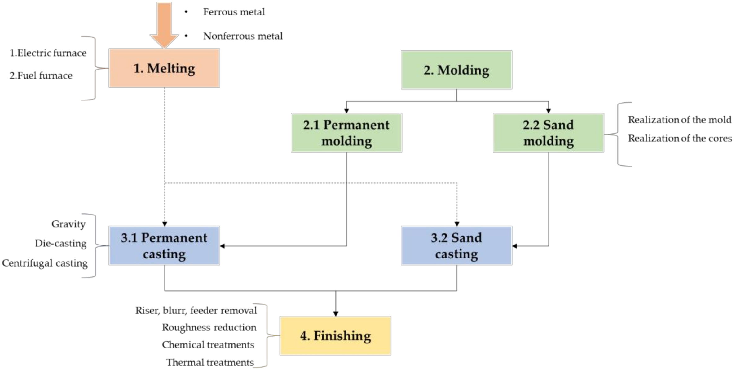
Even though the foundry process could vary based on the kind of metal, which could be ferrous or nonferrous, and depending on company policies, there is a common backbone for all the processes. Indeed, the metal is melted by a furnace, which could be an electric or a fuel furnace. The melting phase is the most energy-intensive phase of the foundry process since it accounts for 70% of the total energy consumption [11]. Specifically, the energy consumption of an electric furnace is between 500 and 700 kWh/ton of metal melted, while the energy consumption related to a furnace fueled by coke is in the range of 90–120 kg/ton of metal melted [12]. With regards to the fuel furnace, the adopted fuel could be coke or methane, which is the most common for nonferrous metals. In parallel with the melting phase, the foundry process is characterized by the molding phase, which consists in the preparation of the molds. A mold is the negative of the realized pieces, and it could include cores to create cavities. Moreover, a mold could be made by sand, or it could be permanent. In case sand molding is adopted, a distinct mold must be created for each produced piece. The materials composing a sand mold are usually silica, olivine sand, and sodium silica, along with other substances such as red mud and blast furnace slag [13]. By contrary, a permanent mold could be used for multiple pieces. Indeed, the mold is made out of metal, and it can be coated with graphite or TO2-based coatings [14]. Downstream the melting and molding phase, the casting phase occurs. The molten metal is poured into the mold, where it solidifies through the heat exchange with the colder mold. For a sand mold, the molten metal is poured through gravity, while, for a permanent mold, a die-casting or a centrifugal casting could also be adopted to let the metal spread within the mold. During this phase, the melted metal must fill all the mold cavity without creating any holes that would be present in the final product. Finally, the solidified metal is extracted from the mold, and it is sent to the finishing phase, which is tasked with the removal of all the risers, feeders, burrs, and superficial sand inclusion, along with improving the surface roughness. The finishing phase could also include thermal or chemical treatments. A schematic representation of the four main phases characterizing the foundry process is illustrated in Figure 1.
Within the context of the foundry industry, the reference document to pursue a greater energy efficiency is the Best Available Techniques Reference Documents (BREFs) related to metal foundry [12]. The BREFs are documents realized by the European Union with the aim to provide a guideline for improving energy efficiency. In addition to the BREFs, several energy-efficient technological solutions are reported in the literature. For instance, technologies related to the molding and casting phase could be found in References [15,16,17,18,19], respectively. Specifically, the application of additive manufacturing in the foundry process is found in References [15,16,17].
Since reaching a higher degree of energy efficiency and environmental sustainability have become crucial requirements, there are several works on this topic for the foundry and the iron and steel industries of distinct countries. Relevant examples were Reference [20] for the foundry industry of India, while References [21,22,23,24,25,26,27] were related to the iron and steel industries of China, Mexico, and Taiwan, respectively. Similar studies have been conducted for the Italian foundry industry as well [1,28,29]. Both References [1,29] presented energy efficiency opportunities extracted from the analysis of Energy Audits (EAs), reporting information related to the adopted technologies, along with some relevant energy consumption data. Specifically, both of the aforementioned works underline how energy recovery could be accounted as a difficult task in a foundry plant but nevertheless, if possible, may lead to a 20% energy saving. Installing recuperative burners was also described as an effective energy-saving technology. Reference [28] was also based on an extensive analysis on the EAs of five foundry plants; however, it was more focused on auxiliary systems such as lightening, compressors, pumps, and electric motors.
Despite many researchers have been focusing their efforts on the improvements of energy consumption of energy-intensive processes, industrial technology is constantly developing [30]; thus, keeping up with the technological advances could be regarded as a tough task. Accordingly, some technologies could become obsolete and the available technological solutions for energy-saving purposes should be continuously updated. Moreover, there could be a gap between the technologies proposed by the literature and the technologies that the companies are currently investing on. In this context, this paper aims to provide an overview of the current Italian scenario and near future developments related to technological energy-saving opportunities and investments in the foundry industry, leading to an update of previous studies. Moreover, this work tries to determine the economic reasons that drive the companies towards a given solution instead of other viable options. The data required for the present study are extracted from the EAs of 231 distinct Italian foundry manufacturing sites, carried out by companies in the foundry sector to comply with Article 8 of Legislative Decree 102/2014, Italian implementation of the Energy Efficiency Directive (EED) 2012/27/EU. Indeed, consulting companies working on the field is a common practice to gather useful information and relevant feedbacks [31], along with obtaining an overview of the real situation. Finally, compared to previous similar research carried out for the Italian foundry industry [1,28,29], the present study exploits a higher number of Eas, assuring a much consistent sample. Furthermore, the same studies were mainly focused on presenting the available technologies along with some cost and energy-saving data, while an extensive analysis of all the planned and implemented interventions is neglected. This last aspect is fundamental to grasp the past and future investment trends.
It is worth mentioning that only the technological solutions are considered within this study, while the managerial solutions are disregarded. Moreover, this work does not account for the solution related to lightning, installation of sensors, and heating of the offices. By contrary, technological solutions related to heat recovery systems and auxiliary systems are considered for their pivotal role within a foundry plant. Moreover, even though the terms intervention and solution could be regarded as synonyms, the first is used for referring to something that has been implemented or planned by an Italian company, while the latter is a general word that identifies something that has been found in the literature or in the EAs.
The remainder of the present paper is organized as follows. Section 2 defines the steps of the methodology and describes the available data. Section 3 describes the obtained results related to the analysis. Subsequently, Section 4 provides a discussion on the results, and finally, in Section 5, the conclusions are presented.

2. Materials and Methods

The main objective of the present study is to investigate the actual trend of opportunities and investments in energy-saving technologies related to the Italian foundry industry. Indeed, the foundry industry is regarded as a highly energy-intensive sector; therefore, reducing energy consumption is a pivotal task to assure a sustainable and forward-looking management of the production process.

2.1. Background

In October 2012, the EED was published by the European Parliament and Council with the purpose of reaching 20% energy savings before 2020 [32]. The EED reports several legal obligations that the large companies (all companies that are not considered as small and medium enterprises) must follow to fulfill the required energy efficiency increase. Within the developed framework, Article 8 obliges the affected enterprises to produce EAs. As stated by Cantini et al. [31], an EA is a systematic document that is required to assess the current energy consumption profile and evaluate future energy-saving investments. In Italy, the EAs are collected by an agency named ENEA (Italian National Agency for New Technologies, Energy, and the Sustainable Economic Development), which is tasked with the management and control of the application of the EED’s framework on Italian soil. The EAs are uploaded by the companies on the ENEA Audit 102 portal (https://audit102.enea.it/, accessed on 23 December 2019). In Italy, not only large companies but also energy-intensive enterprises are subject to the EA obligation. Energy-intensive companies are those that consume more than 1 GWh of electricity per year, that have tax relief on the electricity bill, and that are registered in the Environmental Energy Services Fund (CSEA) lists.
The EAs, which were received by ENEA in December 2019 (first expiry of the second cycle of mandatory diagnoses after 2015), contain a lot of interesting information, such as the plant location, the plant type, the type of adopted raw material, and the type of finished products manufactured by the companies. However, for the actual work, the most useful information regarded the interventions implemented by the Italian companies between 2015 and 2019, and the interventions that the companies planned to realize between 2019 and 2022. Indeed, the listed energy-saving solutions are essential to define an overview of the Italian most common opportunities and investments to limit energy consumption in the foundry sector.
To pursue the objective of the present paper, three main phases are identified as described by the following subsections.

2.2. Available Technological Solutions for Energy-Saving Purposes

At first, a literature screening on the technologies adopted by the foundry industry is conducted. Then, the obtained list is integrated with the implemented in the last five years and planned interventions found in the EAs. This activity is of prominent importance to define a comprehensive list of possible energy-saving solutions through the integration of real company information and academic studies. Subsequently, the developed list was shared with the experts of the Italian Foundry Trade Association (Assofond) to obtain valuable comments on the applicability of the listed technological solutions. To consider expert observations, the list of detected technologies was presented to the experts during a brainstorming session. The technological solutions were screened one by one and when an expert determined as necessary to add an observation, a discussion started until a common opinion by all the experts was reached. Accordingly, the developed lists of technological opportunities and investments represent a synthetic, yet useful, tool to facilitate companies in choosing appropriate energy-saving solutions.

2.3. Analysis of the Implemented and Planned Interventions in Italy

Within the context of Italian EAs, a given intervention could be proposed by more companies. Thus, to grasp a better understanding of the Italian foundry sector, the frequencies of the energy-saving technologies extracted through the EAs are estimated. Indeed, the adoption of relevant statistical parameters is pivotal to point out the most popular interventions, along with determining possible past and future trends. Denoting by SD, the total number of manufacturing sites that produced the EA and the frequencies of the implemented and planned interventions are computed through Equations (1) and (2), respectively.
f i ,   i = n i , i S D   ,
f p ,   i = n p , i S D   ,
where n i , i identifies the number of companies that implemented the ith intervention between 2015 and 2019, while n p , i   denotes the number of companies that proposed the ith intervention as a future development. Finally, f i ,   i and f p ,   i represents the frequency of implementation and planning associated with the ith intervention.
It is worth mentioning that the foundry process could be characterized by an electric or by a fuel furnace. Moreover, the casting phase could occur through the adoption of a permanent or a sand mold. Accordingly, some of the detected interventions could have some applicability limitations. For instance, some technologies could be related to the permanent mold casting; thus, they cannot be adopted by a plant that exploits sand casting. In light of this, new frequencies are defined to get a more truthful and accurate description of the Italian foundry industry. Particularly, given an intervention extracted from the EAs, the new frequencies consider as a sample the number of plants where the aforementioned intervention is implementable (i.e., just a portion of the original sample). Consequently, the more truthful frequencies of the implemented and planned interventions are estimated through Equations (3) and (4), respectively.
f r e l e v a n t _ i ,   i = n i , i r e f e r e n c e _ S D   ,
f r e l e v a n t _ p ,   i = n p , i r e f e r e n c e _ S D   ,
where n i , i and n p , i still identify the number of companies that, respectively, implemented and planned the ith intervention, while r e f e r e n c e _ S D is the reduced sample size representing all the companies that could adopt the ith intervention. Finally, f r e l e v a n t _ i ,   i and f r e l e v a n t _ p ,   i denote the new frequencies related to the implementation and the planning.
The estimated frequencies could be useful to detect a trend and underline the most popular interventions in the Italian foundry industry, but they are not sufficient to justify whether an intervention is better than another one.

2.4. Quantitative Economic Analysis of the Gathered Eneregy Saving Interventions

Some of the EAs included data regarding cost, energy savings, and payback period related to the most relevant interventions. Thus, these data were collected and analyzed to determine the reasons that led the companies to adopt a specific energy-saving solution rather than others. Compared to Section 2.2, this phase allows to analyze the adopted interventions from an economic point of view, considering both the investment cost and the expected energy savings associated with each considered intervention. Specifically, a cost-effectiveness indicator is estimated as illustrated by Equation (5)
c o s t e f f e c t i v e n e s s   i n d i c a t o r = E u r o   i n v e s t e d   Ton   of   Oil   Equivalent   toe of   energy   saved   ton   ,

3. Results

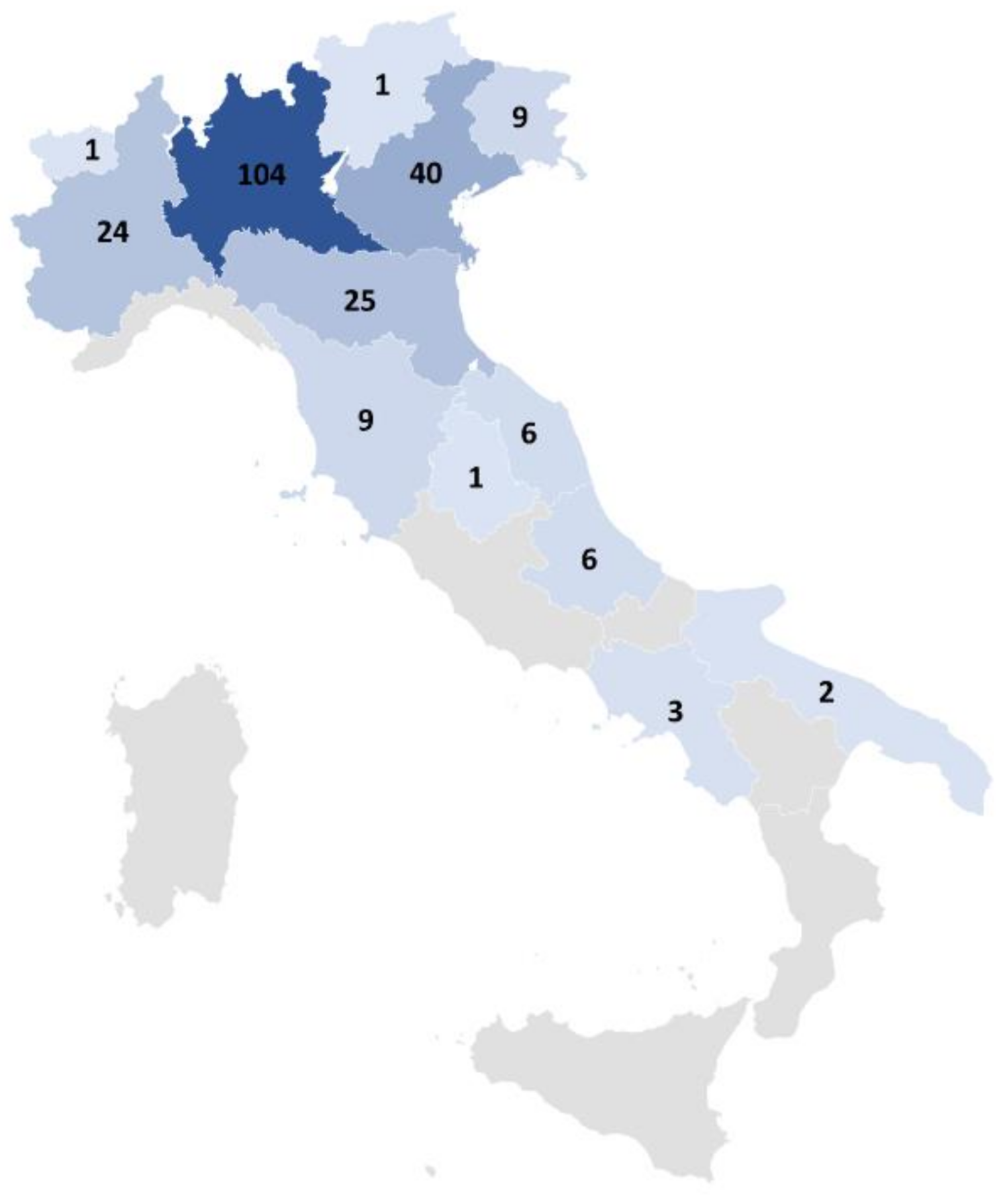
The EAs were provided by 231 different manufacturing sites scattered around all Italy, with a higher density in the Lombardy Region with a total amount of 104 plants (see Figure 2). Moreover, the northern regions contain 204 sites, while 22 sites belong to the central regions, and finally, just 5 plants are located in the South of Italy. Finally, 23% of the 231 plants are considered as big enterprises, while the remaining ones are regarded as small and medium enterprises. All 231 plants are required to procure an EA.
Considering the Nomenclature of Economic Activities (NACE), the analyzed manufacturing processes comprehend the following class: (i) Casting of iron (NACE code 24.51), (ii) Casting of steel (NACE code 24.52), (iii) Casting of light material (NACE code 24.53), and (iv) Casting of non-iron ferrous material (NACE code 24.54). However, a coarser classification has been adopted for the present study by distinguish between ferrous metal casting and nonferrous metal casting, which can be identified, respectively, by the first two and the last two NACE codes.
By analyzing the 231 EAs, it emerged that 89 manufacturing sites work with ferrous metal (mainly cast iron), while 134 plants are devoted to nonferrous metal casting (mainly aluminum). Finally, seven plants realize artifacts with both ferrous and nonferrous metals. A summary of the aforementioned classification is reported by Table 1.
As previously mentioned, a foundry plant could work with an electric or a fuel furnace based on management policies and choices. Accordingly, the 231 plants were classified based on the exploited type of furnace as well. It was found that 78 foundry sites operate with an electric furnace, while a fuel furnace is adopted by 132 processes. The remaining 21 sites comprehend both an electric and a gas furnace. These findings are listed by Table 2. It is worth mentioning that the analyzed steel foundries adopt only electric furnace, while 60% of the cast-iron production sites exploit an electric furnace. Half of the remaining cast-iron plants (20%) use a coke furnace, while the other half are characterized by a gas furnace. Finally, the majority of nonferrous manufacturing sites have a gas furnace.
Finally, the last division has been identified between sites that adopt permanent casting and sites that use sand casting. Particularly, among the 231 production plants, 130 exploit permanent casting, while 91 have implemented side casting. Additionally, 10 manufacturing processes includes both permanent and side casting, as revealed by Table 3.
It is worth mentioning that there is a great difference between a sand casting and a permanent casting process. Indeed, a sand mold is less expensive than a permanent mold, but it is needed to realize a new mold for each produced piece. By contrary, the investment cost related to a permanent mold is higher, but it leads to higher productivity and less finishing requirements of the casted products.

3.1. List of Energy-Saving Technologies Obtained through the Literature and EAs

A literature review was conducted to obtain a preliminary list of available technologies related to the foundry sector. Next, to provide a broader overview of the technologies that could be adopted, the implemented and planned interventions extrapolated from the EAs were integrated with the available literature. Finally, to validate the obtained output, the list of technologies was screened by two foundry experts who provided precious observations regarding the applicability of some technological solutions, along with eliminating unnecessary solutions and adding relevant ones. The two experts that took part in the process belong to the staff of the Italian foundry association and have, respectively, more than 20 and 30 years of experience.
The detected technological solutions were divided by process phases to make them more user-friendly and understandable. As an example, in Table 4, the technologies found for the melting phase are listed, while the tables related to the other phases are reported in Appendix A. In each table, the third column refers to the solution that can be implemented to improve a specific process stage, while the first and the second columns, respectively, identify the machinery and the object associated with the technological solution. Moreover, each technology found in the literature is accompanied by the related bibliographic references (fifth column), while the experts’ comments are listed in the sixth column. Finally, the technological alternatives found in the Eas are reported in italics. Therefore, there could be three different types of technologies:
  • Technologies that are reported in italics and characterized by one or more bibliographic references. These technologies are found both in the literature and in the Eas.
  • Technologies that are reported in black. These technologies are only found in the literature
  • Technologies that are reported in italics and characterized by no bibliographic reference. These technologies are only found in the Eas.
To make a meaningful difference an energy hierarchy that specifies the energy approach was introduced in the fourth column. Specifically, the energy hierarchy is based on three levels similarly to what were done by Reference [33], where seven levels were used. The different energy approaches and their hierarchy are as follows:
  • Innovation: introduce a completely new technology for a part of the process or that is tasked with something that was not done before.
  • Replace: replacing a given technology with a more efficient and/or modern ones. Compared to the previous level, it introduces less changes.
  • Recover: recover thermal or electric energy.
  • Resource: change the source of energy.
Table 4. Technological energy-saving solutions for melting obtained from both the literature and Eas.
Melting
Process MachinerySolution ObjectEnergy-Saving ApproachEnergy-Saving Technological SolutionReferenceComments from Sector Experts
Furnace feedersFurnace feedersRecoverPreheating the row material through the exhaust fumes[34,35]This solution was very common in the past, but it is now less popular due to the high costs. It could be interesting in case the exhaust gas is adopted to preheat the scrap before entry the furnace.
FurnaceBurnersInnovationInstalling recuperative burners[36]
FurnaceBurnersInnovationInstalling low NOx burners to reduce the emission[34]
FurnaceBurnersReplaceReplacing the existing burners with more modern and efficient ones[34]
FurnaceBurnersInnovationInstalling regenerative burners[34]
FurnaceBurnersInnovationInstalling oxy-fuel burners[37,38]This solution is mandatory and it is adopted in all the cast iron plants with rotating furnaces.
FurnaceBurnersInnovationInstalling a combustor for a no flame combustion[34,38]
FurnaceFurnaceReplaceReplacing the existing furnace with a more modern and efficient one[34]
FurnaceFurnaceInnovationAdopting IGBT technology for electric furnace[39]
FurnaceFurnaceInnovationInstalling Ultra High Power transformer to increase the voltage of the electric arc furnace[8]Few companies adopt this solution, which is typical of steel foundry process characterized by smaller furnaces compared to steel production. It should be evaluated if this intervention could be convenient in a foundry plant since the furnace size and its degree of utilization are different compared to the iron and steel industry.
FurnaceFurnaceRe-sourceInstalling Oxy-oil technology to exploit oil as fuel and reducing the consumption of coke along with the emission[8]There is no similar application in Italy
FurnaceFurnaceReplaceInstalling an efficient water-cooled furnace[27]A water-cooling system is already present.
FurnaceFurnaceReplaceReplacing the refractory material of the furnace with a new one to reduce the heat dispersion[27,40]Increasing the thickness of the refractory material leads to a reduction of the furnace production capacity, even though it assists in reducing the energy consumption. Moreover, increasing the thickness of the refractory material causes less space available for the raw material.
FurnaceFurnaceInnovationInstalling Electron Beam Furnace[35]
FurnaceFurnaceInnovationInstalling Solar Furnace[35]
FurnaceFurnaceInnovationInstalling Plasma Furnace[35]
FurnaceFurnaceInnovationInstalling Immersion Heaters[35]
FurnaceFurnaceInnovationInstalling Microwave melting technology[35]
FurnaceRecovery systemInnovationInstalling machines to recover metal from slag[41]Slag is usually selected depending on the furnace type; thus, its chemical composition is known.
FurnacePneumatic powder injectorInnovationInstalling a pneumatic injector to send to the furnace the dust trapped within the air filters[42]It leads to higher energy consumption and slag production. It assists in decreasing the environmental impact.
FurnacePneumatic injector lanceInnovationInstalling a pneumatic injector lance to blow away the slag from the combustion area[42]This solution inerts the slag, leading to a reduction of environmental impact. However, it could increase the energy consumption.

3.2. Frequencies of the Interventions Extracted from the Eas

After extracting the implemented and planned interventions from the Eas, the frequencies associated with each intervention was computed as explained in Section 2.3. The results of the calculation are shown in Table 5, where an italic intervention represents an intervention that is found only in the Eas.
It is possible to state that the estimated frequencies provide a description about the adopted strategies to reduce energy consumption in the Italian foundry industry. Indeed, high values of f r e l e v a n t _ i , i denote a common intervention exploited by the Italian companies in the last five years for energy-saving purposes. Indeed, since f r e l e v a n t _ i , i represents the percentage of plants that implemented the ith intervention, the higher the value of f r e l e v a n t _ i , i , the more popular a given intervention has been during the past years. Moreover, f r e l e v a n t _ p ,   i represents the portion of companies that are willing to adopt a certain technological intervention, giving a hint on possible future developments. Indeed, high values of f r e l e v a n t _ p ,   i indicates an intervention that could be soon very popular since a high number of Italian foundry plants are planning to implement that intervention in the next future.
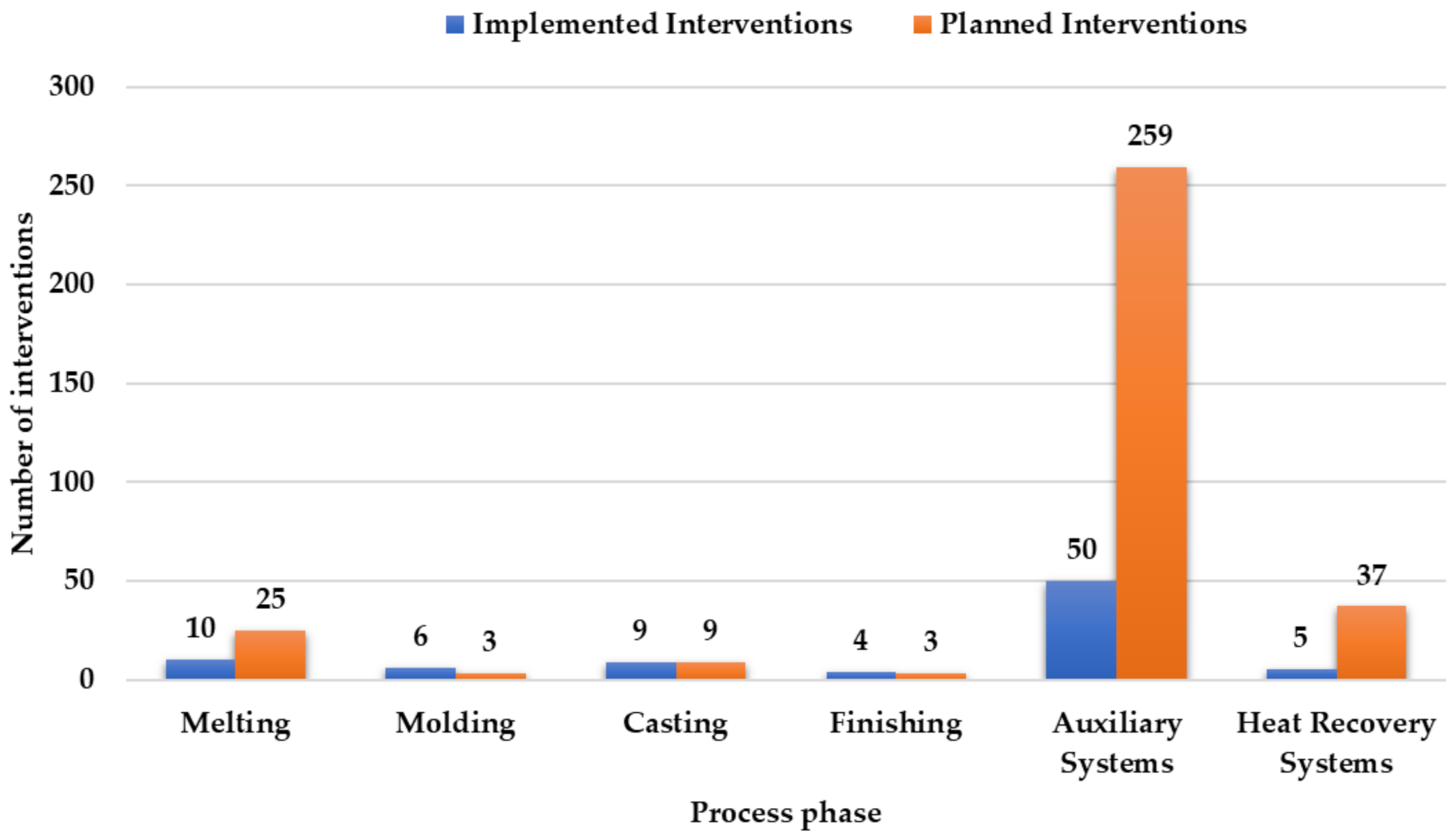
Figure 3 illustrates the number of interventions implemented and planned for each process phase, considering the auxiliary and the heat recovery systems as a separate phase.
It emerged that the companies prefer investing in auxiliary systems, which are characterized by 50 implemented interventions and 259 planned interventions. Accordingly, 59% of the implemented interventions and 77% of the planned interventions involve the auxiliary equipment. In contrast, less interest is devoted to the other process phases among which the heat recovery systems result the most considered one, with five implemented interventions and 37 planned interventions. Since the melting phase is the most energy-intensive, many efforts and investments are focused on it. Specifically, the melting phase has seen a total of 10 implemented interventions and 25 planned interventions. Finally, the finishing phase is the most neglected phase, since it is not relevant in all the manufacturing sites. For instance, the plants that adopt permanent mold casting are usually characterized by less effort on the finishing phase.
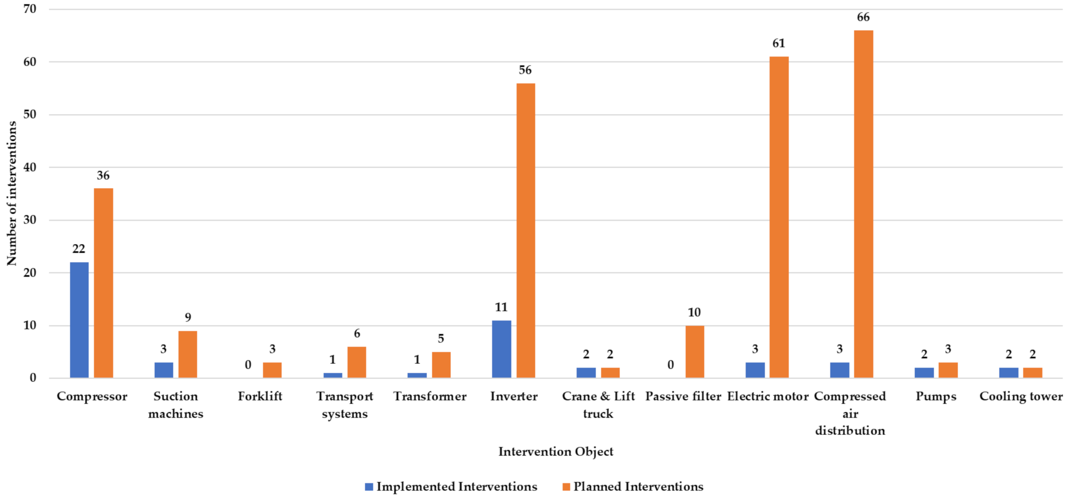
To illustrate even further the obtained results, the implemented and planned interventions for each intervention object related to the auxiliary systems, the heat recovery systems, and the melting phase are illustrated by Figure 4, Figure 5 and Figure 6, respectively. Indeed, it is interesting to highlight the distributions of the interventions associated with the three most relevant “phases”.
Considering the auxiliary systems, the most interventions were adopted for the compressors, which are characterized by 22 implemented interventions; among which, 21 interventions were regarded the replacement of old compressor with newer and more efficient ones (see Table 5). Indeed, the aforementioned intervention is associated with the highest f r e l e v a n t _ i , i , which is estimated at 0.09. This value identifies a trend of the implemented interventions, since almost 9% of the companies replaced the compressors between 2015 and 2019. Moreover, the replacement of compressors with more efficient ones has been planned by 33 enterprises, leading to a f r e l e v a n t _ p , i equal to 0.14. Accordingly, this intervention is still regarded as one of the most beneficial. Finally, 56, 61, and 66 companies planned an intervention related to inverters, electric motors, and air distribution systems, respectively. Thus, it is expected to see an increase of the number of interventions associated with the three aforementioned intervention objects during the next years. Considering the inverters, 56 companies are willing to install new ones or replace the old ones, leading to a f r e l e v a n t _ p , i of 0.24. However, the highest values of f r e l e v a n t _ p , i are associated with the reduction of leaks in the air distribution systems (66 planned interventions) and the replacement of electric motors with more efficient ones (56 planned interventions). Indeed, the last two interventions yield a f r e l e v a n t _ p , i of 0.29 and 0.24, respectively.
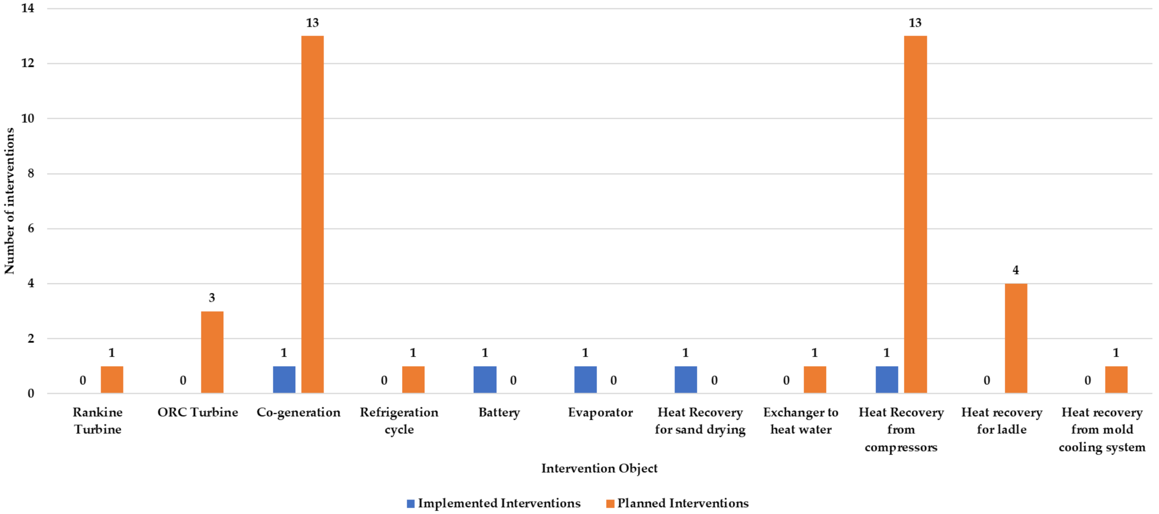
The heat recovery systems are mostly characterized by planned interventions; among which, the most popular one consists in installing a heat recovery system to retrieve heat from the compressor. This intervention is associated with a f r e l e v a n t _ p , i equal to 0.056, which identifies the possibility that 6% of the companies will adopt this intervention during the next years. The installation of a cogeneration system could also become a common intervention during the next years, since it yields a f r e l e v a n t _ p , i of 0.056 as well.
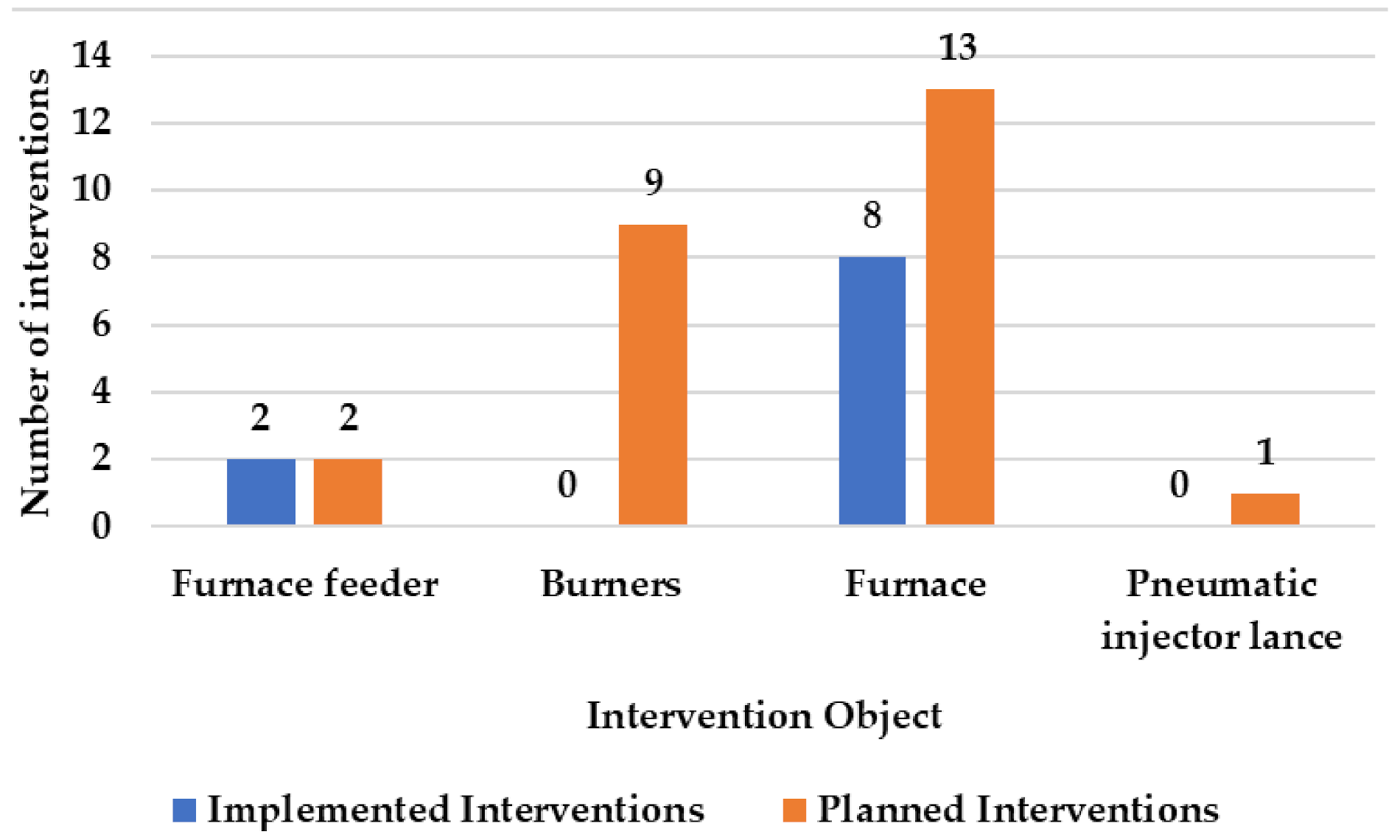
Finally, with regards to the melting phase, most of the implemented interventions is related to the furnace, which has seen eight interventions; among which, six interventions consisted of replacing the old furnace with a more efficient one, leading to a f r e l e v a n t _ i , i of 0.026. Installing a more efficient furnace has also been planned by 11 companies, resulting in a f r e l e v a n t _ p , i equal to 0.045.

3.3. Cost–Benefit Quantitative Analysis

Companies also reported quantitative data on the savings achieved by implementing technological interventions. A total of 84 implemented interventions with quantitative information were listed in the analyzed 231 EAs. Among them, the focus in this article is on technological areas of intervention related to the production process, auxiliary systems and heat recovery systems: they are summarized in Table 6 and Table 7. In the tables, toe stands for ton of oil equivalent, and savings are in terms of final energy. (The column “Other savings” refers to a mix of electric and thermal savings for which the disaggregation in the two components was not available in the energy audit or to savings of other energy vectors.) Production lines determine large energy savings and the largest economic investments (both total and average). Interventions on electric or fuel furnaces are included in this area, coherently with the technological interventions shown in Table 7, and these are largely represented by replacing the existing furnace with a more modern and efficient one. Pressure systems are the second area both in terms of savings and total investment, whereas thermal power plant and heat recovery systems are the second area in terms of average investment. The average quantitative data shown in Table 6 and Table 7 was computed as average of the number of production sites that reported quantitative information.
A cost-effectiveness indicator was calculated for each intervention, measured as Euros invested per Ton of Oil Equivalent (toe) of energy saved (see Table 8). The available information allowed to calculate it only on 11 interventions, reporting both information on energy saved and costs. The area of “Engines, inverters, and other electrical installations” shows an advantageous value of the indicator, confirming that this is a type of intervention with a large applicability, also in different industrial sectors.
A total of 840 planned interventions with quantitative information were identified in the EAs examined. For the purpose of this analysis, as already explained for implemented interventions, we disregard solutions related to areas of intervention not related to production process and auxiliary systems such as, for example, lighting, managerial interventions, and production from renewable sources. Table 9 and Table 10 summarize the savings of final energy and investment cost indicated by those companies that proposed a feasibility study. Table 11 reports the cost-effectiveness indicators calculated for the planned interventions. Feasibility studies estimated electrical savings in all areas and thermal savings to be significant in “Thermal power plant and heat recovery systems” and “Production lines and machines” one. As in the applied interventions, also in the planned interventions the highest energy saving was associated with the production lines area, accompanied, however, by a significant investment cost (Table 10). This area shows a high cost-effectiveness indicator, and as shown in Table 4, most technological interventions are applied to furnaces; additionally, in this case, a furnace substitution represents a high share of interventions in this area. Thermal power plant and heat recovery systems have the best value of cost-effectiveness, followed by pressure systems (Table 11).
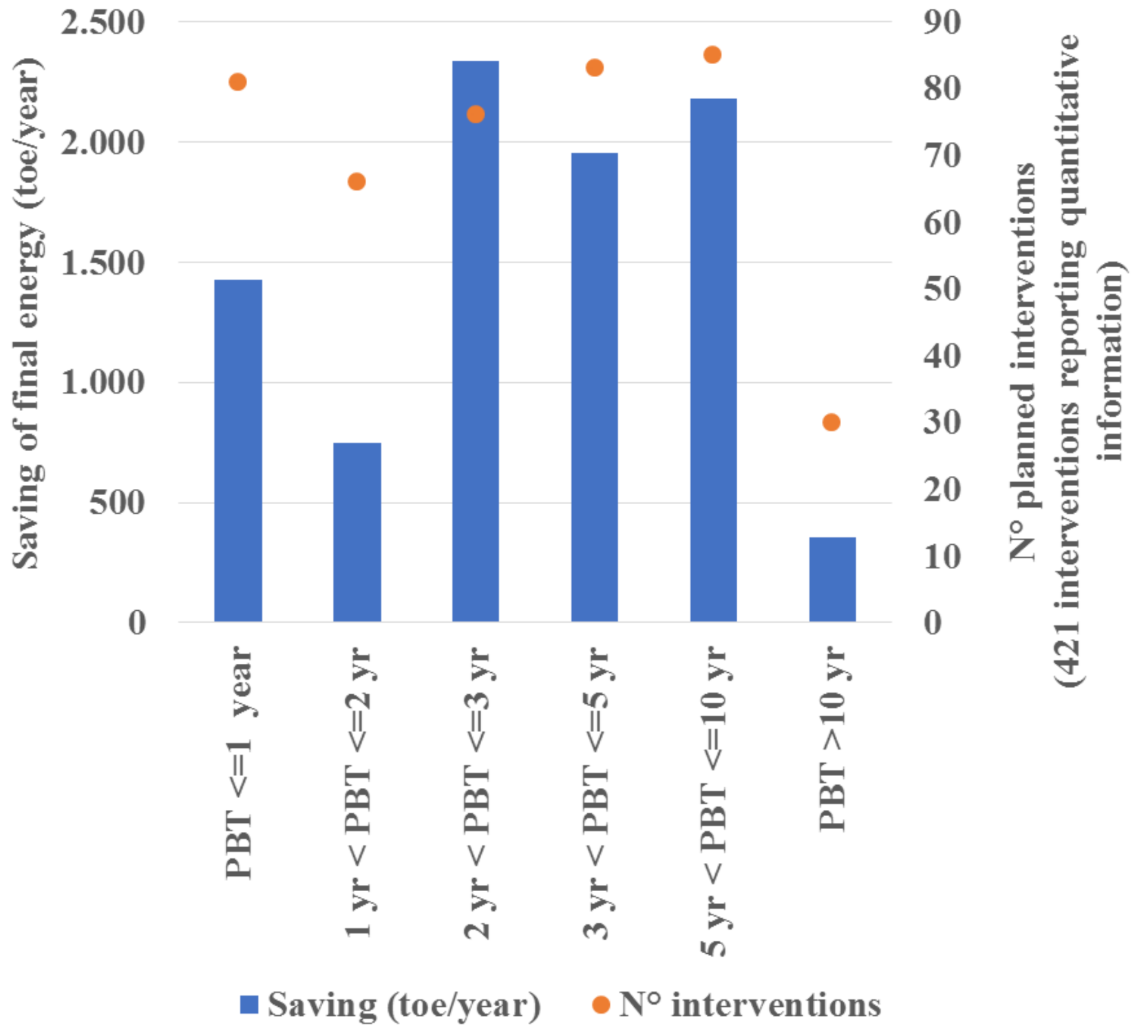
Planned technological interventions can also be analyzed distinguishing for their Payback Time class (PBT; Figure 7). In this case, 421 interventions report quantitative information: interventions with PBT between one and two years represent 8% (2.1 ktoe/year) of the total annual potential saving. Further, 26% of the potential savings is associated with interventions, having a PBT between 2 and 3 years (2.3 ktoe/year).

4. Discussion

As depicted by Figure 3, the auxiliary systems are characterized by the highest number of implemented and planned interventions. This peculiar trend is related to the low investment cost, which results in decent values for the cost-effectiveness indicator and short payback period. Indeed, auxiliary machines are characterized by the lowest investment costs (see Table 10). Moreover, the compressors and pressure systems are associated with the lowest PBT, which is estimated at 2.6 years, and the second cost-effectiveness indicator evaluated at 3252 €/toe (see Table 11) for the planned intervention and 6821 €/toe for the implemented intervention. Furthermore, replacing old compressors with more efficient ones is regarded by the association expert as a very good strategy to reduce energy consumption. On the other side, vacuum systems and electric motors have a PBT of approximately 5 years and a cost-effectiveness indicator estimated at about 6000 €/toe for the planned intervention. Additionally, the engine sector is characterized by the best cost-effectiveness indicator among the implemented interventions (about 3000 €/toe). Another advantage of the interventions related to the auxiliary systems is the easiness of implementation, since the process remains unchanged, and the interventions are mostly characterized by the replacement of an old machine with a more efficient and modern one.
The interventions that act on the heat recovery systems are also quite popular due to the lowest cost-effectiveness indicator of 1935 €/toe (among the planned interventions). Compared to the interventions on auxiliary systems, which are always possible, the interventions related to the heat recovery systems could not always represent a viable option. Indeed, the ability to retrieve heat is limited because of the low temperature characterizing the exhaust gas, leading to some applicability restrictions. For instance, the installation of a cogeneration system is considered by the experts as difficult to implement in a foundry plant. Saying that, the installation of an Organic Rankine Cycle (ORC) turbine and the heat recovery from compressors could become popular interventions in the next future. The ORC turbine exploits lower temperature compared to the more common Rankine turbine, while the heat recovery from compressors is regarded by the experts as an emerging technology which advantages, related to energy-saving indicators, must be evaluated during the next years. Among the interventions concerning heat recovery systems, the installation of an exchanger to retrieve heat and preheat the ladle is worth mentioning. Indeed, the Italian foundry experts state that it is not a common technology, but it has great potential and margin of rationalization. It is worth mentioning that cogeneration and trigeneration interventions are not included in the heat recovery system category, but they are examined as a separate category: planned interventions reporting quantitative information are 10 and correspond to 17,586 toe/year of primary energy saving. The average cost-effectiveness indicator is 1536 €/toe of primary energy; the average PBT is 4 years, thus showing a similar value to heat recovery systems (3.4 years).
Considering the process phases, most of the interventions are implemented and planned for the melting phase, which is the most energy-intensive one. The interventions related to this area are among the most expensive ones, but they assure higher annual energy savings compared to more popular interventions. Furthermore, these kinds of interventions are usually more complex and invasive compared to the interventions related to the auxiliary systems. For instance, replacing the furnace could be very impactful on production schedule and could also lead to more strict requirements with regards to layout and spacing within the plant. However, there are some interventions that are easier to implement, such as the installation of regenerative burners, which is now mandatory and adopted by all the cast iron foundry plants, as stated by the experts.
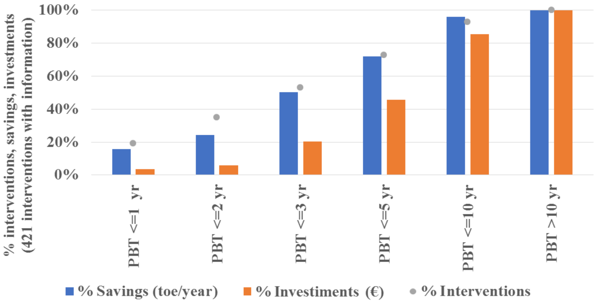
To make a meaningful difference and resume the previous findings, Figure 8 shows that half of potential saving (4.5 ktoe/year) can be achieved by adopting interventions with PBT lower than 3 years and by mobilizing 20% of total investment associated with suggested interventions (around 5.9 million Euro). This highlights that relatively less expensive interventions are associated with a high saving potential, and such a trend appears even more significant when considering that the existing incentive mechanisms are not included within the PBT calculations.
Finally, it is worth mentioning that some technological solutions are found in the literature, but they are not currently implemented or planned by Italian companies. There could be different reasons that leads to this behavior. For instance, some technologies are emerging (e.g., 3D printing for core and mold making), which leads to uncertainty related to their application. Indeed, the costs and benefits of the emerging technology are not always clear, or the companies could be reluctant to implement a technology that is not well-known. Another reason for a low application level could be that a given technological solution is obsolete; thus, companies are not considering it anymore. Another possible reason for a scarce implementation could be that certain technologies could be disruptive for the process and could lead to major changing. As a result, there could be a quite strong resistance to change. Finally, the existing energy efficiency incentive schemes are very likely to have a role in influencing what technological solutions are more often adopted or planned: the policy coverage would evolve over time, including more promising technologies.

5. Conclusions

Given the uncertainties and difficulties that arise when planning energy-saving investments in a foundry plant, a comprehensive analysis on the interventions implemented and planned by 231 Italian manufacturing sites was conducted in this study. The in-depth study involved the EAs provided by the Italian foundry companies, along with foundry expert judgements, leading to obtain an overview of the current Italian developments on energy-saving investments. Indeed, the frequencies related to the implemented interventions provide the past trends, while the frequencies associated with the planned interventions give a hint on future trends. Moreover, as a further step of analysis, the economic data reported by the EAs were examined to determine whether there is a relationship between the adopted technological interventions and economic indicators.
The results of this study pointed out that the companies lean towards investments on the auxiliary systems and the heat recovery systems, while the melting phase has attracted most of the efforts among the process phases. Specifically, the most adopted intervention was the replacement of compressors with more efficient ones, while the most planned intervention is reducing the leakages of the air distribution systems. Among the most popular interventions that the companies are willing to implement, it is worth mentioning the following ones: replacing electric motors and furnaces with more efficient ones, installing cogeneration systems and installing or replacing the inverters. From an economic and energy-efficiency perspectives, it is possible to state that the companies prefer investing in technologies characterized by a short PBT and a decent cost-effectiveness indicator. The cost-effectiveness indicator represents the investment cost for each toe of energy saved; thus, it is strongly related to the reduction of energy consumption. The aforementioned trend is also related to the easiness of implementation of some solutions compared to others. Indeed, considering the interventions related to the heat recovery systems, it is possible to state that they guarantee the best cost-effectiveness indicators and generally higher energy-savings compared to the interventions related to pressure systems, compressors and engines. However, they are characterized by some limitations with regards to implementation.
Another fundamental outcome of this paper is the list of technologies, which have been validated by Italian foundry experts. Indeed, this output represents an up-to-date guideline for companies who are conducting a screening analysis of the possible energy-saving solutions. In other words, the aforementioned list could be exploited as a preliminary decision support tool.
During this work, energy-efficiency strategies related to lighting, heating of offices, and installation of sensors, along with the adoption of proper managerial practices, were not considered. Thus, the presented study could not account for all the possible solutions that can be adopted in a foundry plant to reduce energy consumption.
Further developments could include the analysis of other industrial sectors subjected to the EED, along with duplicating the analysis for the foundry industry of other countries. Indeed, different types of manufacturing plant could have distinct needs, leading to different choices related to energy-saving investments. Additionally, both the prices of electric energy and fuels could vary from nation to nation, resulting in diverse economic opportunities. Finally, another interesting future development could be repeating the study when the next EAs are produced to check whether the companies adopted the planned interventions and point out whether new opportunities have been identified.

Author Contributions

Conceptualization, A.C., L.L. and F.D.C.; methodology, A.C., L.L. and F.D.C.; software, C.T., C.M., M.S., F.M., A.C. and L.L.; validation, A.C., L.L., F.D.C., C.T., F.M., M.S. and C.M.; formal analysis, A.C., L.L. and C.M.; investigation, A.C., L.L. and C.M.; resources, C.M. and M.S.; data curation, A.C., L.L. and C.M.; writing—original draft preparation, L.L.; writing—review and editing, A.C., F.D.C., C.T., C.M., F.M. and M.S.; visualization, L.L.; supervision, F.D.C.; project administration, F.D.C., F.M. and M.S.; and funding acquisition, M.S. and F.M. All authors have read and agreed to the published version of the manuscript.

Funding

This work is part of the Electrical System Research (PTR 2019–2021), implemented under Programme Agreements between the Italian Ministry for Economic Development and ENEA, CNR, and RSE S.p.A.

Institutional Review Board Statement

Not applicable.

Informed Consent Statement

Not applicable.

Data Availability Statement

Data is contained within the article.

Acknowledgments

The authors gratefully acknowledge the technical support provided by the Italian Foundry Association Assofond.

Conflicts of Interest

The authors declare no conflict of interest.

Appendix A

Table A1. Technological energy-saving solutions for molding obtained from both the literature and EAs.
Molding
Process MachinerySolution ObjectEnergy-Saving ApproachEnergy-Saving Technological SolutionReferenceComments from Sector Experts
Molding machinerySand recovery systemInnovationInstalling machine capable of retrieving slag from furnace and using it as sand mold.[43]
Molding machinerySand recovery systemRe-sourceReplacing the electric sand recovery system with a gas oneEnergy AuditsThis solution is in total contrast with the decarbonization requirments.
Molding machinerySand recovery systemInnovationInstalling a sand recovery systemEnergy AuditsThis solution generates an increase of the energy consumption; however, it could help mitigating the environmental impact. Indeed, recovering sand leads to lower level of sand waste and disposal.
Molding machineryMolding stationReplaceReplacing the molding stations with more efficient onesEnergy Audits
Molding machineryMixerReplaceReplacing the mixing systems with a more efficient oneEnergy Audits
Molding machinery“Hot box” moldingInnovationInstalling a preheating system or regenerative or recuperative burners for the furnace tasked with the production of the sand mold[29]
Molding machineryMolding machineryReplaceInstalling an efficient filter for the sand molding processEnergy AuditsThe benefits of this solution should be evaluated considering the compressed air required to clean the filter
Molding machineryMolding machineryInnovationInstalling a infrared system for drying the mold[8,17]This solution is adopted by some Italian foundry plants. It is exploited for both the refractory material of the mold and the coating of the sand mold
Molding machineryMolding machineryInnovationInstalling low-pressure casting machine capable of using inorganic coresEnergy Audits
Molding machineryMolding machineryReplaceReplacing the existing machinery with newer and more efficient ones[8]
Molding machinery3D PrinterInnovationInstalling a 3D Printer (Jet Binding) for making molds[15,44]
Molding machinery3D PrinterInnovationInstalling a 3D Binder Jetting Printer for making cores. The 3D Printer blends the sand through a binder agent[16]Emerging techology; thus, its energy consumption should be evaluated more in-depth. More benefits for low production volumes.
Molding machinery3D PrinterInnovationInstalling 3D Printer for making cores[16]Emerging techology; thus, its energy consumption should be evaluated more in-depth. More benefits for low production volumes.
Table A2. Technological energy-saving solutions for casting obtained from both the literature and EAs.
Casting
Process MachinerySolution ObjectEenergy-Saving ApproachEnergy-Saving Technological SolutionReferenceComments from Sector Experts
Casting machineryCasting machineryInnovationInstalling a Vacuum Suction Casting Technology[15]This solution allows to obtain a better surface roughness, leading to a lower energy consumption during the finishing phase. However, it is an emerging technology and it could lead to high energy consumption due to the requirments of mantaining the vaccum conditions. Before implementing this solution it is recommended to evaluate the energy consumption increase during the casting phase and the energy consumption decrease of the finishing phase.
Casting machineryCooling systemInnovationAdopting the “quench casting” technique for cooling the cast[18]
Casting machineryCooling systemInnovationAdopting the “splash casting” technique for cooling the cast[18]
Casting machineryCooling systemInnovationInstalling a forced ventilation cooling systemEnergy Audits
Casting machineryLadleInnovationInstalling machines capable of scheduling an efficient preheat of the ladle[8,38]It is usually performed without considering energy-saving opportunities. Large margin of potential and rationalization.
Casting machineryLadleInnovationUsing lid for ladle to reduce the heat loss[8]It is a very useful solution with large margin of potential and rationalization.
Casting machineryLadleInnovationAdopting coating material for the ladle to reduce the heat loss[8]It is a very useful solution with large margin of potential and rationalization
Casting machineryLadleReplaceInstalling ladle with a more pointed outled to reduce the porosity of the cast. It also assures a lower thermal dispersion.[45]It is not a common technological solution
Casting machineryLadleInnovationInstalling an automatic ladle pouring system[35]
Casting machineryCasting furnaceReplaceReplacing the casting furnace with a more efficient and newer oneEnergy Audits
Casting machineryCasting machineryReplaceReplacing the casting machineries with more efficient and newer ones[46]
Casting machineryDie-casting machineryReplaceInstalling a new efficient die-casting lineEnergy Audits
Casting machineryDie-casting machineryReplaceReplacing the furnace where the cast waits to be poured in the mold with a more efficient and newer oneEnergy Audits
Sand removal machinerySand removal machineryReplaceReplacing the machinery in charge of the sand removal process with more efficient and newer ones[8]
Table A3. Technological energy-saving solutions for finishing obtained from both the literature and EAs.
Finishing
Process MachinerySolution ObjectEnergy-Saving ApproachEnergy-Saving Technological SolutionReferenceComments from Sector Experts
Finishing stationRobotInnovationInstalling a robot for finishing[47]The automatic operations allows to both reduce cost and save time. Moreover, they limit human interventions leading to a safer process.
Finishing stationFinishing stationReplaceInstalling a new efficient finishing lineEnergy Audits
Finishing stationFinishing stationReplaceReplacing old finishing machineries with more efficient and modern ones[8,24]
Finishing stationFinishing stationReplaceInstalling high efficiency nozzlesEnergy Audits
Heat Treatment FurnaceHeat Treatment FurnaceReplaceReplacing the heat tratment furnace with a more efficient and modern oneEnergy Audits
Table A4. Technological energy-saving solutions for auxiliary systems obtained from both the literature and EAs.
Auxiliary Systems
Process MachinerySolution ObjectEnergy-Saving ApproachEnergy-Saving Technological SolutionReferenceComments from Sector Experts
CompressorsCompressorsReplaceReplacing the compressor with more modern and efficient ones[28]It is a very good technological solution to reduce energy consumption
CompressorsExchangerInnovationImproving the air quality through the introduction of an exchanger located at the compressor outlets[48]
CompressorsFilterInnovationImproving the air quality through the introduction of a filter located at the compressor outlets to remove volatile substances [48]
CompressorsFilterInnovationImproving the air quality through the introduction of a filter to remove oil from compressed air[48]
CompressorsInjection pumpInnovationInstalling a pump for better injecting and sparing the lubrificant [48]
CompressorsCompressorsInnovationInstalling technologies capable of isolating some sections of the system that requires specific values for the pressure of the air[49]
CompressorsCompressorsReplaceOptimize the size of the compressors[49]
CompressorsCompressorsInnovationInstalling an intercooler for the compressors[28,50]
CompressorsCompressorsInnovationInstalling variable speed compressors (i.e., compressor with inverter)[49]
CompressorsCompressorsReplaceInstalling efficient induction motors[49]
CompressorsCompressorsInnovationReplacing the compressors needed for creating vacuum with vacuum pumps[49]
Pressure systemsPressure systemsInnovationReplacing all the equipment for pressurized air distribution with electric or idraulic devices (if possible)[49]It is a very good technological solution to reduce energy consumption
Pressure systemsPressure systemsInnovationReplacing the compressor with fans, blowers or other alternative solutions (if possible)[51]
Lubrification systemLubrification system Installing technologies for electrostatic lubrification to decrease the oil contained in the air[34]
Suction SystemsSuction SystemsInnovationPlaced the suction systems as close as possible to the sources[34]It is a very good technological solution to reduce energy consumption
Suction SystemsSuction SystemsInnovationInstalling defrosters to remove condensation drops[34]
Suction SystemsSuction SystemsInnovationInstalling electrostatic precipitator to remove dust[34]
Suction SystemsSuction SystemsInnovationInstalling appropriate systes to reduce the emissions[36]
Suction SystemsSuction SystemsReplaceInstalling high efficiency fans[8]
Suction SystemsSuction SystemsReplaceInstalling fans with proper size and power[8]
Suction SystemsSuction SystemsInnovationInstalling variable speed fans (i.e., fans with inverter)[8]
Suction SystemsSuction SystemsInnovationInstalling a forced air suction system for the furnaceEnergy Audits
Transport SystemsForkliftReplaceReplacing the forklifts with more efficient and modern ones[52]
Transport SystemsForklift’s batteryReplaceReplacing the batteries of the forklifts[52]
Transport SystemsTransport SystemsReplaceReplacing conveyor belts with more efficient and modern onesEnergy Audits
Transport SystemsTransport SystemsInnovationInstalling appropriate covers and roofings for the material transportation systems[36]
Transport SystemsTransport SystemsInnovationInstalling frequency converters with controlled speed for the transportation systems[53]
Transport SystemsTransport SystemsInnovationReplacing pneumatic, chain and screw transport systems with belt conveying systems[53]
Transport SystemsTransport SystemsReplaceReplacing poly-v belts with more efficient and modern ones[54]
Transport SystemsTransport SystemsInnovationInstalling high efficiency belt and replace V-belts with toothed belts[8]
Transport SystemsTransport SystemsInnovationReplacing V-belts with helicoidal beltsEnergy Audits
Transport SystemsLift truckReplaceReplacing the lift trucks with more efficient and modern onesEnergy Audits
Transport SystemsCraneReplaceReplacing the cranes with more efficient and modern onesEnergy Audits
Electricity TransformersElectricity TransformersReplaceReplacing the electricity transformers with more efficient and modern onesEnergy Audits
InvertersInvertersInnovationInstalling inverters on eletric motors or replacing the inverters with more efficient and modern ones[1]
Electric PlantElectric PlantInnovationInstalling passive filters[34]
EnginesEnginesReplaceInstalling high efficiency electric motors (class IE2, IE3 and IE4)[28,54]It is recommended for all the motors with high working hours.
EnginesEnginesReplaceInstalling electric motors correctly sized in relation to the power required by the system[54]
EnginesEnginesInnovationInstalling regenerative electric motorsEnergy Audits
EnginesEnginesInnovationInstalling motors with low starting current[55]It assures lower consumption and less dependence on the electricity network.
EnginesEnginesReplaceRewinding electric motors[8,55]
EnginesEnginesReplaceRewiring the engines [8]
EnginesEnginesInnovationInstalling variable speed motors (i.e., motors with inverter)[55]
Fluid distribution systemsFluid distribution systemsReplaceInstalling a closed circuit cooling system[36]
Fluid distribution systemsFluid distribution systemsInnovationOptimize the pipelines’ design leakage along with installing appropriate seal to minimize air leakage[49,56]
Fluid distribution systemsFluid distribution systemsReplaceInstalling a proper insulation for the fluid distribution system to reduce heat loss[8]
PumpsPumpsReplaceReplacing the pumps with more efficient and modern ones[8]
PumpsPumpsReplaceInstalling pumps correctly sized [8]
PumpsPumpsReplaceTrim the impellers of the pumps to reduce the energy consumption[8]
PumpsPumpsInnovationInstalling variable speed pumps (i.e., pumps with inverter) [8]
Cooling SystemsCooling SystemsReplaceReplacing the cooling towers with more efficient and modern onesEnergy Audits
Cooling SystemsCooling SystemsInnovationInstalling technologies able to reuse the condensation of the cooling towers[8]
Table A5. Technological energy-saving solutions for heat recovery systems obtained from both the literature and EAs.
Heat Recovery Systems
Process MachinerySolution ObjectEnergy-Saving ApproachEnergy-Saving Technological SolutionReferenceComments from Sector Experts
FurnaceHeat Recovery SystemsRecoverInstalling a heat recovery system to retrieve heat from the slag[57]
FurnaceHeat Recovery SystemsRecoverInstalling a preheater for the combustion air[36]
FurnaceHeat Recovery SystemsRecoverInstalling a regenerator to retrieve heat from exhaust gas[35]
FurnaceHeat Recovery SystemsRecoverInstalling a recuperator to retrieve heat from exhaust gas[35]
FurnaceHeat Recovery SystemsInnovation Installing Carbon Capture and Utilization (CCU) technology for capturing the CO2 contained in the exhaust gas and exploit it for other purposes[58]This is an emerging solution; thus, it is not easily implementable for small and medium enterprises
Rankine turbineHeat Recovery SystemsRecoverInstalling a Rankine turbine to generate electric energy through the exhaust gas[34,38]
Combined cycleHeat Recovery SystemsRecoverInstalling technologies able to exploits exhaust gas to produce electric energy through a combined cycle[59]It is usually adopted for gas cupola furnace
ORC turbineHeat Recovery SystemsRecoverInstalling a ORC turbine to generate electric energy through the exhaust gas[8,38,56]It could be adopted for medium cupola furnaces, which are exploited for at least two shifts
BurnerHeat Recovery SystemsInnovationInstalling a burner able to capture organic volatile substances to burn them and produce heat[5]This is an interesting technology in case the post-combustion could be totally fueled with the volatile substances, otherwise methane is required, leading to economic unsustainability
CogenerationHeat Recovery SystemsRecoverInstalling cogeneration or trigeneration technologies[8]This solution is not easily implementable in a foundry plant
Refrigeration cycleHeat Recovery SystemsRecoverInstalling technologies able to exploits the exhaust gas for a refrigeration cycle[60]
BatteryHeat Recovery SystemsReplaceReplacing the batteries of the heat recovery systems[61]
EvaporatorHeat Recovery SystemsRecoverInstalling an evaporator to retrieve heat from the emulsified waterEnergy AuditsIt is adopted for the nonferrous metals produced through die-casting
Sand drying systemHeat Recovery SystemsRecoverInstalling technologies for the sand drying processEnergy Audits
FurnaceHeat Recovery SystemsRecoverInstalling an exchanger to retrieve heat from the exhaust gas and generate hot water for the drierEnergy Audits
FurnaceHeat Recovery SystemsRecoverInstalling a turbine to retrieve heat from the high pressure of the furnace[24,57]
Storage TankHeat Recovery SystemsRecoverInstalling a heat storage tank[56]
CompressorExchangerRecoverInstalling an exchanger to retrieve heat from the compressors[49,56]
LadleExchangerRecoverInstalling an exchanger to retrieve heat and preheat the ladle[51]It is not a common technology; however, it has a large margin of potential and rationalization
Casting machineryCooling systemRecoverInstalling a heat recovery system from the cooling process of the moldsEnergy Audits

References

  1. Noro, M.; Lazzarin, R. Energy audit experiences in foundries. Int. J. Energy Environ. Eng. 2016, 7, 409–423. [Google Scholar] [CrossRef] [Green Version]
  2. Corelli, G. La Razionalizzazione dei Processi di Fonderia. Available online: https://www.castingitaly.com/ (accessed on 22 April 2021).
  3. Kermeli, K.; Deuchler, R.; Worrell, E.; Masanet, E.R. Energy Efficiency Improvement and Cost Saving Opportunities for Metal Casting: An ENERGY STAR® Guide for Energy and Plant Managers. Environmental Protection Agency: Washington, DC, USA. 2016. Available online: https://www.energystar.gov/sites/default/files/tools/ENERGY%20STAR%20Metal%20Casting%20Energy%20Guide.pdf (accessed on 1 December 2021).
  4. Thollander, P.; Backlund, S.; Trianni, A.; Cagno, E. Beyond barriers–A case study on driving forces for improved energy efficiency in the foundry industries in Finland, France, Germany, Italy, Poland, Spain, and Sweden. Appl. Energy 2013, 111, 636–643. [Google Scholar] [CrossRef] [Green Version]
  5. Sa, A.; Paramonova, S.; Thollander, P.; Cagno, E. Classification of industrial energy management practices: A case study of a Swedish foundry. Energy Procedia 2015, 75, 2581–2588. [Google Scholar] [CrossRef] [Green Version]
  6. Thollander, P.; Ottosson, M. Energy management practices in Swedish energy-intensive industries. J. Clean. Prod. 2010, 18, 1125–1133. [Google Scholar] [CrossRef] [Green Version]
  7. Vinci, G.; D’Ascenzo, F.; Esposito, A.; Musarra, M.; Rapa, M.; Rocchi, A. A sustainable innovation in the Italian glass production: LCA and Eco-Care matrix evaluation. J. Clean. Prod. 2019, 223, 587–595. [Google Scholar] [CrossRef]
  8. Worrell, E.; Blinde, P.; Neelis, M.; Blomen, E.; Masanet, E. Energy Efficiency Improvement and Cost Saving Opportunities for the US Iron and Steel Industry an ENERGY STAR (R) Guide for Energy and Plant Managers; Lawrence Berkeley National Lab. (LBNL): Berkeley, CA, USA, 2010. [Google Scholar]
  9. Pastor-López, I.; Santos, I.; Santamaría-Ibirika, A.; Salazar, M.; De-la-Peña-Sordo, J.; Bringas, P.G. Machine-learning-based surface defect detection and categorisation in high-precision foundry. In Proceedings of the 2012 7th IEEE Conference on Industrial Electronics and Applications (ICIEA), Singapore, 18–20 July 2012; pp. 1359–1364. [Google Scholar]
  10. Assofond. Assofond—Il Processo di Fonderia. Available online: https://www.assofond.it/il-processo-di-fonderia(accessed on 22 April 2021).
  11. Arasu, M.; Jeffrey, L.R. Energy consumption studies in cast iron foundries. In Proceedings of the Transactions of 57th IFC, Kolkata, India, 13–15 February 2009; pp. 331–336. [Google Scholar]
  12. Prevention, I.P. Control Reference Document on Best Available Techniques in the Smitheries and Foundries Industry; European Commission: Bruxelles, Belgium, 2005. [Google Scholar]
  13. Sinha, N.K.; Choudhary, I.; Singh, J. Influence of Mold Material on the Mold Stability for Foundry Use. Silicon 2021, 1–10. [Google Scholar] [CrossRef]
  14. Hamasaiid, A.; Dargusch, M.; Davidson, C.; Tovar, S.; Loulou, T.; Rezai-Aria, F.; Dour, G. Effect of mold coating materials and thickness on heat transfer in permanent mold casting of aluminum alloys. Metall. Mater. Trans. A 2007, 38, 1303–1316. [Google Scholar] [CrossRef] [Green Version]
  15. Rodríguez-González, P.; Robles Valero, P.; Fernández-Abia, A.; Castro-Sastre, M.; Barreiro García, J. Application of Vacuum Techniques in Shell Moulds Produced by Additive Manufacturing. Metals 2020, 10, 1090. [Google Scholar] [CrossRef]
  16. Lynch, P.; Hasbrouck, C.; Wilck, J.; Kay, M.; Manogharan, G. Challenges and opportunities to integrate the oldest and newest manufacturing processes: Metal casting and additive manufacturing. Rapid Prototyp. J. 2020. [CrossRef]
  17. Wang, J.; Sama, S.R.; Manogharan, G. Re-Thinking Design Methodology for Castings: 3D Sand-Printing and Topology Optimization. Int. J. Met. 2019, 13, 2–17. [Google Scholar] [CrossRef]
  18. Acar, S.; Guler, K.A. A Preliminary Study Upon the Applicability of the Direct Water Cooling with the Lost Foam Casting Process. Int. J. Met. 2021, 15, 88–97. [Google Scholar] [CrossRef]
  19. Lee, J.; Lee, Y.C.; Kim, J.T. Migration from the traditional to the smart factory in the die-casting industry: Novel process data acquisition and fault detection based on artificial neural network. J. Mater. Process. Technol. 2021, 290, 116972. [Google Scholar] [CrossRef]
  20. Patange, G.; Khond, M. Some studies on energy consumptions and identification of suitable energy management techniques in Indian foundry industries. Eur. Sci. J. 2013, 9, 241–252. [Google Scholar]
  21. Price, L.; Sinton, J.; Worrell, E.; Phylipsen, D.; Xiulian, H.; Ji, L. Energy use and carbon dioxide emissions from steel production in China. Energy 2002, 27, 429–446. [Google Scholar] [CrossRef]
  22. Lin, B.; Wang, X. Promoting energy conservation in China’s iron & steel sector. Energy 2014, 73, 465–474. [Google Scholar]
  23. Wei, Y.-M.; Liao, H.; Fan, Y. An empirical analysis of energy efficiency in China’s iron and steel sector. Energy 2007, 32, 2262–2270. [Google Scholar] [CrossRef]
  24. Guo, Z.; Fu, Z. Current situation of energy consumption and measures taken for energy saving in the iron and steel industry in China. Energy 2010, 35, 4356–4360. [Google Scholar] [CrossRef]
  25. Zhang, J.; Wang, G. Energy saving technologies and productive efficiency in the Chinese iron and steel sector. Energy 2008, 33, 525–537. [Google Scholar] [CrossRef]
  26. Ozawa, L.; Sheinbaum, C.; Martin, N.; Worrell, E.; Price, L. Energy use and CO2 emissions in Mexico’s iron and steel industry. Energy 2002, 27, 225–239. [Google Scholar] [CrossRef]
  27. Chan, D.Y.-L.; Yang, K.-H.; Lee, J.-D.; Hong, G.-B. The case study of furnace use and energy conservation in iron and steel industry. Energy 2010, 35, 1665–1670. [Google Scholar] [CrossRef]
  28. Lazzarin, R.M.; Noro, M. Energy efficiency opportunities in the service plants of cast iron foundries in Italy. Int. J. Low-Carbon Technol. 2017, 12, 96–109. [Google Scholar] [CrossRef]
  29. Lazzarin, R.M.; Noro, M. Energy efficiency opportunities in the production process of cast iron foundries: An experience in Italy. Appl. Therm. Eng. 2015, 90, 509–520. [Google Scholar] [CrossRef]
  30. Hasanbeigi, A.; Price, L.; Lin, E. Emerging energy-efficiency and CO2 emission-reduction technologies for cement and concrete production: A technical review. Renew. Sustain. Energy Rev. 2012, 16, 6220–6238. [Google Scholar] [CrossRef] [Green Version]
  31. Cantini, A.; Leoni, L.; De Carlo, F.; Salvio, M.; Martini, C.; Martini, F. Technological Energy Efficiency Improvements in Cement Industries. Sustainability 2021, 13, 3810. [Google Scholar] [CrossRef]
  32. European Parliament and Council, Energy Efficiency Directive 2012/27/EU (EED). 2012. Available online: https://eur-lex.europa.eu/LexUriServ/LexUriServ.do?uri=OJ:L:2012:315:0001:0056:en:PDF (accessed on 5 December 2021).
  33. Enright, N. The resource EFFICIENCY Hierarchy. Available online: https://www.sustainsuccess.co.uk/the-resource-efficiency-hierarchy (accessed on 23 November 2021).
  34. Roudier, S.; Sancho, L.D.; Remus, R.; Aguado-Monsonet, M. Best Available Techniques (BAT) Reference Document for Iron and Steel Production: Industrial Emissions Directive 2010/75/EU: Integrated Pollution Prevention and Control; Publications of the European Union Luxembourg: Luxembourg, 2013. [Google Scholar]
  35. BCS Incorporated. Advanced Melting Technologies: Energy Saving Concepts and Opportunities for the Metal Casting Industry; BCS Incorporated: Boston, MA, USA, 2005. [Google Scholar]
  36. Cusano, G.; Gonzalo, M.; Farrell, F.; Remus, R.; Roudier, S.; Sancho, L. Best Available Techniques (BAT) Reference Document for the Non-Ferrous Metals Industries-Industrial Emissions Directive 2010/75/EU (Integrated Pollution Prevention and Control); Publications of the European Union: Luxembourg, 2017. [Google Scholar]
  37. Pardo, N.; Moya, J.A. Prospective scenarios on energy efficiency and CO2 emissions in the European Iron & Steel industry. Energy 2013, 54, 113–128. [Google Scholar]
  38. Eronen, S.; Tapola, M.; Svensson, E.; Sommarin, P.; Helber, J.; Piatek, J.; Przybylski, J.; Caballero, P.; Kemppainen, P. Improving the Energy Efficiency of Foundries in Europe Foundrybench—Foundry Energy Efficiency Benchmarking Project (IEE/07/585/SI2.500402); European Commission: Bruxelles, Belgium, 2012. [Google Scholar]
  39. Grunbaum, R. Voltage source converters for maintaining of power quality and stability in power distribution. Proceedings of 2005 European Conference on Power Electronics and Applications, Dresden, Germany, 11–14 September 2005. [Google Scholar]
  40. Sako, E.Y.; Orsolini, H.D.; Moreira, M.; de Meo, C.E.; Pelissari, P.I.; Salvini, V.R.; Pandolfelli, V.C. Thermal ceramic coatings as energy saving alternatives for high temperature processes. Int. J. Appl. Ceram. Technol. 2020, 17, 2492–2508. [Google Scholar] [CrossRef]
  41. Sibanda, V.; Sipunga, E.; Danha, G.; Mamvura, T.A. Enhancing the flotation recovery of copper minerals in smelter slags from Namibia prior to disposal. Heliyon 2020, 6, e03135. [Google Scholar] [CrossRef] [Green Version]
  42. Jezierski, J.; Janerka, K. Wastes utilisation in foundries and metallurgical plants with pneumatic conveying techniques–selected aspects. Interdiscip. Environ. Rev. 2011, 12, 154–165. [Google Scholar] [CrossRef]
  43. Prabhushankar, N.; Balaji, N. Various Alternative Sources for Silica Sand, Binders and Additives in Sand Casting and their Properties—A Review. IOP Conf. Ser. Mater. Sci. Eng. 2020, 993, 012137. [Google Scholar] [CrossRef]
  44. Sama, S.R.; Badamo, T.; Manogharan, G. Case studies on integrating 3d sand-printing technology into the production portfolio of a sand-casting foundry. Int. J. Met. 2020, 14, 12–24. [Google Scholar] [CrossRef]
  45. Choi, J.; Hwang, H.; Kang, S. Effect of ladle outlet geometry on internal porosity in gravity casting automotive brackets: An experimental investigation. China Foundry 2020, 17, 56–60. [Google Scholar] [CrossRef] [Green Version]
  46. Bonollo, F.; Gramegna, N.; Timelli, G. High-pressure die-casting: Contradictions and challenges. JOM 2015, 67, 901–908. [Google Scholar] [CrossRef]
  47. Gruzman, V. Foundry production digitalization. IOP Conf. Ser. Mater. Sci. Eng. 2020, 966, 012127. [Google Scholar] [CrossRef]
  48. Wrona, R.; Ziółkowski, E.; Smyksy, K.; Brzeziński, M. The quality of compressed air as the necessary condition the improving the process efficiency in foundry plants. Arch. Foundry Eng. 2013, 13, 107–111. [Google Scholar] [CrossRef]
  49. Eras, J.J.C.; Gutiérrez, A.S.; Santos, V.S.; Ulloa, M.J.C. Energy management of compressed air systems. Assessing the production and use of compressed air in industry. Energy 2020, 213, 118662. [Google Scholar] [CrossRef]
  50. Šarevski, M.N.; Šarevski, V.N. Thermal characteristics of high-temperature R718 heat pumps with turbo compressor thermal vapor recompression. Appl. Therm. Eng. 2017, 117, 355–365. [Google Scholar] [CrossRef]
  51. Institute For Industrial Productivity. Explore Energy Efficiency Technologies across the Industrial Sectors. Available online: http://www.iipinetwork.org/wp-content/Ietd/content/institute-industrial-productivity.html (accessed on 11 January 2021).
  52. Artal-Sevil, J.; Bernal-Agustín, J.; Dufo-López, R.; Domínguez-Navarro, J. Forklifts, Automated Guided Vehicles and Horizontal Order Pickers in Industrial Environments. Energy Management of an Active Hybrid Power System based on Batteries, PEM Fuel Cells and Ultracapacitors. Renew. Energy Power Qual. J. (REPQJ) 2017. [Google Scholar] [CrossRef]
  53. Pang, Y.; Lodewijks, G. Improving energy efficiency in material transport systems by fuzzy speed control. In Proceedings of the 3rd IEEE International Symposium on Logistics and Industrial Informatics, Budapest, Hungary, 25–27 August 2011; pp. 159–164. [Google Scholar]
  54. Abdel-Hadi, A.; Salem, A.R.; Abbas, A.I.; Qandil, M.; Amano, R.S. Study of Energy Saving Analysis for Different Industries. J. Energy Resour. Technol. 2021, 143, 052101. [Google Scholar] [CrossRef]
  55. Kurilin, S.; Denisov, V.; Dli, M.; Bobkov, V. Scientific and technical directions of improvement of electric motors for non-ferrous metallurgy. Non-Ferr. Met. 2019, 47, 53–58. [Google Scholar] [CrossRef]
  56. Helber, J.S.M. Good Practice Guide on Energy Saving POTENTIALS and Opportunities for foundries. Foundrybench—Foundry Energy Efficiency Benchmarking Project, (IEE/07/585/SI2.500402); European Commission: Bruxelles, Belgium, 2011. [Google Scholar]
  57. Holappa, L. Energy efficiency and sustainability in steel production. In Applications of Process Engineering Principles in Materials Processing, Energy and Environmental Technologies; Springer: Cham, Switzerland, 2017; pp. 401–410. [Google Scholar]
  58. Hammerschmid, M.; Müller, S.; Fuchs, J.; Hofbauer, H. Evaluation of biomass-based production of below zero emission reducing gas for the iron and steel industry. Biomass Convers. Biorefinery 2021, 11, 169–187. [Google Scholar] [CrossRef]
  59. Ryzhkov, A.; Levin, E.; Filippov, P.; Abaimov, N.; Gordeev, S. Making more efficient use of blast-furnace gas at Russian metallurgical plants. Metallurgist 2016, 60, 19–30. [Google Scholar] [CrossRef]
  60. Chen, L.; Yang, B.; Shen, X.; Xie, Z.; Sun, F. Thermodynamic optimization opportunities for the recovery and utilization of residual energy and heat in China’s iron and steel industry: A case study. Appl. Therm. Eng. 2015, 86, 151–160. [Google Scholar] [CrossRef]
  61. Zhang, Y.; Shi, Y.; Zhang, L.; Li, J.; Fu, Q.; Zhu, X.; Liao, Q. A fluidized-bed reactor for enhanced mass transfer and increased performance in thermally regenerative batteries for low-grade waste heat recovery. J. Power Source 2021, 495, 229815. [Google Scholar] [CrossRef]
Figure 1. Main phases of the foundry production process.
Energies 14 08470 g001
Figure 2. Geographical distribution of the 231 Italian foundry plants constituting the investigated sample.
Energies 14 08470 g002
Figure 3. Number of implemented and planned interventions for each process phase.
Energies 14 08470 g003
Figure 4. Number of implemented and planned interventions for the auxiliary systems.
Energies 14 08470 g004
Figure 5. Number of implemented and planned interventions for the heat recovery systems.
Energies 14 08470 g005
Figure 6. Number of implemented and planned interventions for the melting phase.
Energies 14 08470 g006
Figure 7. Annual saving and planned interventions according to the PBT classes.
Energies 14 08470 g007
Figure 8. Cumulative saving and investment according to PBT classes.
Energies 14 08470 g008
Table 1. Types of casted metal of the 231 manufacturing sites.
Type of Casted MetalManufacturing SitesPercentage of the Sample
Ferrous8939%
Nonferrous13458%
Both73%
Table 2. Types of adopted furnace by the 231 manufacturing sites.
Type of FurnaceManufacturing SitesPercentage of the Sample
Electric7833.8%
Fuel13257.1%
Both219.1%
Table 3. Types of adopted casting by the 231 manufacturing sites.
Type of CastingManufacturing SitesPercentage of the Sample
Permanent13056.3%
Sand9139.4%
Both104.3%
Table 5. Number of companies that implement and plan a given intervention, along with its associated frequencies.
Process StageIntervention ObjectEnergy-Saving ApproachIntervention n i , i n p , i f i , i f p , i f r e l e v a n t _ i , i f r e l e v a n t _ p , i
MeltingFurnace feedersRecoverPreheating the row material through the exhaust fumes220.00870.00870.00870.0087
MeltingBurnersInnovationInstalling recuperative burners0700.030300.046
MeltingBurnersReplaceReplacing the existing burners with more modern and efficient ones0100.004300.0065
MeltingBurnersInnovationInstalling regenerative burners0100.004300.0065
MeltingFurnaceReplaceReplacing the existing furnace with a more modern and efficient one6110.0260.0480.0260.048
MeltingFurnaceInnovationAdopting IGBT technology for electric furnace0100.004300.01
MeltingFurnaceReplaceReplacing the refractory material of the furnace with a new one to reduce the heat dispersion 210.00870.00430.0130.0065
MeltingPneumatic injector lanceInnovationInstalling a pneumatic injector lance to blow away the slag from the combustion area 0100.004300.0043
MoldingSand recovery systemRe-sourceReplacing the electric sand recovery system with a gas one0100.004300.0099
MoldingSand recovery systemInnovationInstalling a sand recovery system100.004300.00990
MoldingMolding stationReplaceReplacing the molding stations with more efficient ones100.004300.00990
MoldingMixerReplaceReplacing the mixing systems with a more efficient one200.008700.020
Molding“Hot box” moldingInnovationInstalling a pre-heating system or regenerative or recuperative burners for the furnace tasked with the production of the sand mold 100.004300.00990
MoldingMolding machineryInnovationInstalling low-pressure casting machine capable of using inorganic cores0100.004300.0099
MoldingMolding machineryReplaceInstalling an efficient filter for the sand molding process0100.004300.0099
MoldingMolding machineryReplaceReplacing the existing machinery with newer and more efficient ones100.004300.00990
CastingCasting furnaceReplaceReplacing the casting furnace with a more efficient and newer one100.004300.00430
CastingCooling systemInnovationInstalling a forced ventilation cooling system100.004300.00710
CastingCasting machineryReplaceReplacing the casting machineries with more efficient and newer ones420.0170.00870.0290.014
CastingDie-casting machineryReplaceReplacing the furnace where the cast waits to be poured in the mold with a more efficient and newer one230.00870.0130.0140.021
CastingDie-casting machineryReplaceInstalling a new efficient die-casting line0300.004300.0099
CastingSand removal machineryReplaceReplacing the machinery in charge of the sand removal process with more efficient and newer ones100.004300.00430
CastingLadleInnovationInstalling machines capable of scheduling an efficient preheat of the ladle 0100.04300.043
FinishingFinishing stationReplaceInstalling a new efficient finishing line200.008700.00870
FinishingFinishing stationReplaceInstalling high efficiency nozzles0100.004300.0043
FinishingFinishing stationReplaceReplacing old finishing machineries with more efficient and modern ones210.00870.00430.00870.0043
FinishingHeat Treatment FurnaceReplaceReplacing the heat electric furnace with a more efficient and modern one0100.004300.0043
Auxiliary SystemsCompressorsReplaceReplacing the compressor with more modern and efficient ones21330.0910.140.0910.14
Auxiliary SystemsCompressorsInnovationInstalling variable speed compressors (i.e., compressor with inverter)0300.01300.013
Auxiliary SystemsPressure SystemsInnovationReplacing all the equipment for pressurized air distribution with electric devices (if possible)100.004300.00430
Auxiliary SystemsSuction SystemsReplaceInstalling high efficiency fans160.00430.0260.00430.026
Auxiliary SystemsSuction SystemsInnovationInstalling variable speed fans (i.e., fans with inverter)130.00430.0130.00430.013
Auxiliary SystemsSuction SystemsInnovationInstalling a forced air suction system for the furnace100.004300.00430
Auxiliary SystemsForkliftsReplaceReplacing the forklifts with more efficient and modern ones0100.004300.0043
Auxiliary SystemsForklits’ BatteriesReplaceReplacing the batteries of the forklifts0200.008700.0087
Auxiliary SystemsTransport SystemsReplaceReplacing conveyor belts with more efficient and modern ones100.004300.00430
Auxiliary SystemsTransport SystemsInnovationInstalling high efficiency belt and replace V-belts with toothed belts0500.02200.022
Auxiliary SystemsTransport SystemsInnovationReplacing V-belts with helicoidal belts0100.004300.0043
Auxiliary SystemsElectric TransformersReplaceReplacing the electricity transformers with more efficient and modern ones150.00430.0220.00430.022
Auxiliary SystemsInverterInnovationInstalling inverters on electric motors or replacing the inverters with more efficient and modern ones11560.0480.240.0480.24
Auxiliary SystemsLift TruckReplaceReplacing the lift trucks with more efficient and modern ones0100.004300.0043
Auxiliary SystemsCraneReplaceReplacing the cranes with more efficient and modern ones210.00870.00430.00870.0043
Auxiliary SystemsPassive filterInnovationInstalling passive filters01000.04300.043
Auxiliary SystemsEnginesReplaceInstalling high efficiency electric motors (class IE2, IE3 and IE4)3560.0130.240.0130.24
Auxiliary SystemsEnginesInnovationInstalling regenerative electric motors0200.008700.0087
Auxiliary SystemsEnginesReplaceRewinding electric motors0100.004300.0043
Auxiliary SystemsEnginesInnovationInstalling variable speed motors (i.e., motors with inverter)0200.008700.0087
Auxiliary SystemsFluid Distribution SystemInnovationOptimize the pipelines’ design leakage along with installing appropriate seal to minimize air leakage3660.0130.290.0130.29
Auxiliary SystemsPumpsReplaceReplacing the pumps with more efficient and modern ones230.00870.0130.00870.013
Auxiliary SystemsCooling SystemsReplaceReplacing the cooling towers with more efficient and modern ones220.00870.00870.00870.0087
Heat Recovery SystemsRankine turbineRecoverInstalling a Rankine turbine to generate electric energy through the exhaust gas0100.004300.0043
Heat Recovery SystemsORC turbineRecoverInstalling a ORC turbine to generate electric energy through the exhaust gas0300.01300.013
Heat Recovery SystemsCogenerationRecoverInstalling cogeneration or trigeneration technologies1130.00430.05620.00430.056
Heat Recovery SystemsRefrigeration cycleRecoverInstalling technologies able to exploits the exhaust gas for a refrigeration cycle0100.004300.0043
Heat Recovery SystemsBatteryReplaceReplacing the batteries of the heat recovery systems100.004300.00430
Heat Recovery SystemsEvaporatorRecoverInstalling an evaporator to retrieve heat from the emulsified water100.004300.00430
Heat Recovery SystemsSand drying systemRecoverInstalling technologies for the sand drying process100.004300.00430
Heat Recovery SystemsExchangerRecoverInstalling an exchanger to retrieve heat from the exhaust gas and generate hot water for the drier0100.004300.0043
Heat Recovery SystemsExchangerRecoverInstalling an exchanger to retrieve heat from the compressors1130.00430.0560.00430.056
Heat Recovery SystemsCooling systemRecoverInstalling a heat recovery system from the cooling process of the molds0100.004300.0071
Heat Recovery SystemsExchangerRecoverInstalling an exchanger to retrieve heat and preheat the ladle0400.01700.017
Total84336
Table 6. Energy savings produced by the implemented technological interventions in the various areas of intervention. The total annual savings are calculated as the sum of thermal energy, electricity, and fuel savings.
Area of InterventionProduction Sites Reporting Quantitative InformationElectricity Savings (Toe/Year)Thermal Energy Savings (Toe/Year)Other Savings (Toe/Year)Annual Savings (Toe/Year)Annual Savings (%)Average Annual Savings (Toe/Year)
Pressure systems1432601333919%24
Intake system8117001177%15
Thermal power plant and heat recovery systems3059441036%34
Engines, inverters, and other electrical installations390090%3
Production lines and machines14348258610121768%87
Total428013176671784100%-
Table 7. Investments required to apply technological interventions in the various areas of intervention.
Area of Intervention# Production Sites Reporting Quantitative InformationTotal Investment (€)Total Investment (%)Average Investment (€)
Pressure systems191,791,06817%94,267
Intake system9666,4286%74,487
Thermal power plant and heat recovery systems3615,5006%205,166
Engines, inverters, and other electrical installations7430,6204%71,770
Production lines and machines207,347,95668%367,398
Total5810,851,572100%-
Table 8. Cost-effectiveness indicator for each area of intervention.
Area of InterventionProduction Sites Reporting Quantitative InformationCost-Effectiveness Indicator (€/toe)
Pressure systems146821
Intake system715,340
Thermal power plant and heat recovery systems0-
Engines, inverters, and other electrical installations33101
Production lines and machines1113,900
Table 9. Energy savings assessed for the planned technological interventions in the various areas of intervention. The total annual savings are calculated as the sum of thermal energy, electricity, and fuel savings.
Area of InterventionProduction Sites Reporting Quantitative InformationAnnual Electricity Savings (Toe/Year)Annual Thermal Energy Savings (Toe/Year)Other Savings (Toe/Year)Annual Savings (Toe/Year)Annual Savings (%)Average Annual Savings (Toe/Year)
Pressure systems14213164764142714%10
Intake system71569005696%8
Thermal power plant and heat recovery systems567419171264292229%52
Engines, inverters, and other electrical installations14910720128120012%600
Production lines and machines6520751380437389239%3892
Total48310,0092344189314,246100%-
Table 10. Investments assessed for the planned interventions for distinct areas of intervention.
Area of Intervention# Production Sites Reporting Quantitative InformationTotal Investment
(€)
Total Investment (%)Average Investment (€)
Pressure systems1353,549,17611%26,290
Intake system732,662,4378%36,472
Thermal power plant and heat recovery systems537,023,60621%132,521
Engines, inverters, and other electrical installations1485,646,49617%48,872
Production lines and machines6814,568,16544%214,238
Total47730,787,442100%-
Table 11. Cost-effectiveness indicator for each area of intervention.
Area of Intervention# Production Sites Reporting Quantitative InformationCost-Effectiveness Indicator
(€/toe)
Pay-Back Time (Years)
Pressure systems13332522.6
Vacuum system7162324.9
Thermal power plant and heat recovery systems5219353.4
Engines, inverters, and other electrical installations14366225.2
Production lines and machines6110,0895.6
Publisher’s Note: MDPI stays neutral with regard to jurisdictional claims in published maps and institutional affiliations.

