
Concept of a Dual Energy Storage System for Sustainable Energy Supply of Automated Guided Vehicles


Institute for Material Handling and Logistics, Karlsruhe Institute of Technology, 76131 Karlsruhe, Germany
*
Author to whom correspondence should be addressed.
Energies 2022, 15(2), 479; https://0-doi-org.brum.beds.ac.uk/10.3390/en15020479
Submission received: 17 December 2021
/
Revised: 3 January 2022
/
Accepted: 4 January 2022
/
Published: 10 January 2022
(This article belongs to the Special Issue Hybrid Energy Storage Based on Battery and Ultracapacitor)
Abstract
:Due to the growing number of automated guided vehicles (AGVs) in use in industry, as well as the increasing demand for limited raw materials, such as lithium for electric vehicles (EV), a more sustainable solution for mobile energy storage in AGVs is being sought. This paper presents a dual energy storage system (DESS) concept, based on a combination of an electrical (supercapacitors) and an electro-chemical energy storage system (battery), used separately depending on the required transport distance. Each energy storage unit (ESU) in this DESS is capable of supplying the AGV completely. The concept takes into account requirements for a complex material flow as well as minimizing the energy storage capacity required for the operation of the AGV. An energy flow analysis is performed and further used as a basis to derive three possible circuit concepts for the technical realization. The circuit concepts are compared to other approaches from related work, differentiating the functionality to hybrid energy storage systems (HESS). The functionality of the concepts was validated by mapping the energy flow states to active circuit components. Finally, an approach for implementing the control strategy as a state machine is given, and conclusions for further investigations are drawn.
1. Introduction
Manufacturing and distribution companies today have increasingly complex material flow processes. These processes can be implemented with a combination traditional continuous conveyors, such as belt or roller conveyors, as well as discontinuous conveyors, such as forklifts, or lift carts. In addition to these solutions, automated guided vehicles (AGVs) are increasingly utilized as a flexible approach for implementing complex material flows.
The 2010s saw a steadily increasing demand for automated guided vehicle systems (AGVS) accompanied by a rapid increase in the amount of system and component manufacturers on the market [1]. Further research into optimizing these systems appears both economically and environmentally beneficial. Furthermore, the global logistics industry has been shaped by the desire for sustainable production as well as logistics.
The term “green logistics” is used to heighten the environmental awareness of companies towards their logistic processes. This includes sustainability in the sense of resource- and energy-efficient development of logistics systems and processes. Due to the change to the age of e-mobility, the demand for resources for the production of energy storage systems (ESS) is increasing enormously.
One approach to improving sustainability and resource efficiency when using AGVs in intralogistics is to reduce the capacity of the ESS used to a necessary minimum. Current AGVs usually feature large ESSs designed for several hours of operation. Due to the mostly missing fast charging possibility, battery changing or vehicle redundancy in the fleet is necessary to maintain system availability while the vehicles are being charged.
The amount of energy stored in batteries is considerably larger than in SC storage systems. The use of supercapacitors (SC) as energy storage in AGVs has disadvantages compared to conventional electrochemical ESS (i.e., batteries). First, an AGV with a battery is more flexible in terms of transport distances due to the significantly higher energy density of batteries. SC based AGVs require more charging systems (CS), which can be installed at every load transfer station or, for example, along long sections of the route to be used as intermediate CSs.
The challenge is to design an ESS that meets the requirements of both a complex material flow and minimizing the energy storage capacity needed to operate the AGV. In this paper, a concept of a dual energy storage system (DESS) is introduced, intended to improve the sustainability of AGVs and thus to contribute towards greener logistics. Furthermore, the disadvantages of an SC system compared to a battery system in an AGV are to be minimized. The targeted use of the two different energy storage units (ESU), based on the current transport task and route, can guarantee flexibility with respect to varying transport distances.
Compared to other DESS or hybrid ESS (HESS), which mainly target peak power shaving and battery lifetime extension, the DESS concept introduced here allows fully supplying the AGV from either the SC or the battery. The SC is used as the sole ESU for short distances, with the battery for long distances. The battery is gradually charged from the SC during consecutive short transport tasks, allowing for very fast charging during stops at load transfer stations. An additional aim with the DESS concept is to increase the operational availability of AGVs compared to systems based only on SC or batteries.
The challenges of this work were to find a system solution that meets the requirements of both a complex material flow and minimizing the energy storage capacity needed to operate an AGV. For the approach presented in this paper, a control strategy was developed in which both short and long distances can be taken into account, and these can be linked together under logical conditions. Based on this, the necessary energy flow states were determined, which result from the process steps of the control strategy. Finally, circuit concepts were determined, taking resource minimization into account, which can support the required energy flow states to support the DESS concept.
The paper starts in Section 2 with the technical fundamentals of energy supply of AGVs, related work on control strategies of AGVs and circuit concepts of hybrid energy storage systems (HESS). In Section 3 of this paper, the DESS concept is described, alongside the previously mentioned challenges of control strategy, energy flow analysis and the development of circuit concepts. In Section 4, the control strategy is analyzed and evaluated, and an approach for the realization of the control by a state machine is presented.
Further, the conceived circuit concepts are analyzed and compared with related work and validated by the mapping of energy flow states and active converters. The conclusion presents a summary of the core aspects of the concept presented in this paper. Finally, the results of the analysis are reviewed in Section 4, and an outlook on the planned further work is given, which includes empirical investigations.
2. Background
2.1. Structure of an AGV
Automated guided vehicles (AGV), also called mobile transport robots or mobile transport systems are used—for example, for the automated material supply and disposal of production plants, for the flexible conveyance of goods, as well as for the transport of entire semi-finished products. They essentially consist of a traction drive (i.e., drives), a vehicle control system (i.e., Control), an ESS, sensors for environment and obstacle detection, devices for load handling and an energy transmission system.
AGVs are part of an AGVS, which, in addition to the vehicles themselves, includes other peripherals, such as a control system with order management, a transport layout, as well as load transfer systems and CSs. Figure 1 illustrates the components of an AGVS and their AGV.
An AGV is usually powered by electricity and has an ESS, which is usually a rechargeable battery. In order to supply vehicle control and electric drives, as well as other sensors and actuators with energy, voltage regulators (i.e., DC–DC converters) are required that generate a constant supply voltage from the fluctuating voltage of the energy storage. The voltage fluctuations depend on the type of energy storage, the size of the energy storage, the state of charge, the electrical load and the age of the ESS [2,3].
2.2. Current Energy Storage Systems in AGVs
Electrochemical ESS, such as lead-acid and lithium-ion (Li-ion) batteries, as well as electrical ESS, such as electric double-layer capacitors (EDLC, also known as supercapacitors (SC) or boost capacitors), are used as ESS for AGVs. Lead-acid batteries come in a variety of designs. These include liquid electrolyte lead-acid batteries. Further developed lead-gel or lead-flow batteries have solid electrolytes. The gravimetric energy density describes the ratio between the maximum storable energy and the total mass.
Due to the many factors influencing service life and high charging times, lead-acid batteries are economically best suited for capacitive operation where the battery is used until it is completely discharged (see Section 2.4, (A)) [3]. Li-ion batteries are also available in different versions, e.g., as a compound with iron phosphate or titanium (lithium titanate oxide accumulator, LTO).
Li-ion ESS are widely used in new AGVSs, as this is the most widespread energy storage solution on the market [3] and has also become accepted as a suitable energy storage solution in EVs [4]. Compared to lead-acid batteries or EDLC, smaller control devices can also be operated directly from the battery without a DC–DC converter. EDLC have a particularly high energy density compared to typical electrolytic capacitors. In 2019, EDLC with capacitance values between 10 F and 5000 F are available on the market and thus cover the capacitance range between electrolytic capacitors and batteries [5].
Despite the comparatively high energy-related acquisition costs, EDLC are also used as a proven solution for energy supply in AGVs. Compared to electro-chemical ESS, such as Li-ion or lead-acid batteries, EDLC are clearly superior in terms of their possible large charging current and the associated shorter charging time. Likewise, the expected cyclic, as well as calendar lifetime of an EDLC is greater than that of an electrochemical battery [3,5].
On the other hand, an argument against the use of EDLC as a stand-alone ESS in an AGV is that the electrical energy can only be stored efficiently for a short time. This is due to the high self-discharge rate, which is reported in studies [6,7] to be 5% to 60% voltage loss in 14 days.
An EDLC also occupies more space volume compared to an electro-chemical battery of similar capacity. Table 1 shows the typical characteristics of the previously mentioned energy storage types.
2.3. Charging Systems for AGVs
A charging system (CS) is required to charge ESS. This consists of at least one current-controlled voltage power supply unit for converting the mains voltage to a DC voltage and an energy transmission system. Depending on the vehicle and energy storage type, the technical characteristics of the system components vary. For most ESS, a “CC-CV charging” (constant current–constant voltage) process is used, in which the ESS is charged in two stages, first “charging with constant current” and second “charging with constant voltage”.
In the first state, the ESS is charged with a variable voltage and a constant charging current. When the voltage reaches the cell-specific end-of-charge voltage, the previously still variable charging voltage is kept constant at the end-of-charge voltage. The charging current decreases according to the state of charge of the ESS. When the charge current falls below a lower charge current threshold or after a set charge duration has elapsed, the ESS is regarded as fully charged and the charging process is complete.
The charging processes can be automatic or manual. In the context of this paper, only automatic charging processes without regular intervention by people, e.g., manual plugging in and unplugging of the charging connector, are considered.
2.4. Operating and Charging Strategies
An operating strategy regulates the behavior of the AGVs in the overall system. It determines which vehicle processes which transport order in which sequence. Furthermore, an operating strategy implies charging strategies that regulate the energy supply of the AGVs. These are explained in more detail in the following subsection (cf. Section 2.4).
According to [13], charging strategies can be divided into two categories. In the first category, no active monitoring of the storage capacity is performed. In this case, the ESS is designed for a specific operating time and is charged after the operating time has ended. A decision-making and monitoring system is not required. In the second category, the state of charge and other characteristics of the ESS of each AGV during operation are monitored continuously.
In this category, a computing unit is required to make decisions regarding charging operations. This can be implemented as a central computing unit that evaluates the state of all AGVs or in a decentralized manner within each vehicle control system. The following charging strategies can be assigned to the second category (based on [3,14,15,16,17]):
- (A)
- Capacitive operation.
- (B)
- Capacitive operation with intermediate charging.
- (C)
- Gradually reduced capacity limit.
- (D)
- Opportunity charging.
- (E)
- Shifted battery charging cycles (cycle strategy).
- (F)
- Neural network-based energy management.
- (G)
- Minimum delay charging station.
In charging strategy A, a lower capacity threshold is defined. If the capacity falls below the threshold, the transport order is completed, and the vehicle then moves to a free CS. Intermediate charging, for example in the case of a low volume of transport orders, is covered by charging strategy B. A lower capacity threshold is also defined for this strategy.
Contrary to charging strategy A is the possibility of intermediate charging, for example at load transfer points or in buffer sections. Charging strategy C builds on charging strategy B. The aim of this charging strategy is to avoid simultaneous charging of several vehicles and to maintain the availability of the overall system. For this purpose, a capacity limit is defined that is dynamically adjusted to the required availability of the system.
For example, in an AGVS with four fully charged AGVs, the first vehicle would be charged at a capacity discharge of 80%, the second vehicle at 60% and the third vehicle at 40 % [14]. Charging strategy D describes opportunity charging, in which every opportunity during operation is used for charging. This includes, for example, downtimes of the entire system, intermediate charging at load transfer stations or in buffer sections, or charging during the absence of new transport orders. Permanent intermediate charging allows the system to be used in 24-h operation [3,15].
In charging strategy E, the assumption is made that all vehicle batteries cycle continuously. At the same time, the availability of the overall system is to be kept constant. For this purpose, the vehicles are charged and put back into operation at evenly distributed intervals. A further approach is the use of a neural network to assign transport orders or charging instructions to the vehicles (charging strategy F). For the user, the decision making of the neural network is not comprehensible, but still shows an improvement in terms of charging strategy A according to [16].
The last charging strategy (charging strategy G) listed here describes a charging strategy, which is referred to by Zhan et al. as “minimum delay charging station” [17]. This takes into account the minimum expected waiting time at the charging stations, which can occur in case the charging stations are occupied.
2.5. Related Work
This section describes the current state of research on HESS and DESS and highlights their weaknesses with regard to their use in AGVs. In the scope of this publication, a DESS refers to an ESS that consists of two different energy storage types that can be used independently of each other as the stand-alone energy source to supply energy to AGVs.
The goal of power smoothing during acceleration and deceleration phases as pursued in HESS, where the SC is used to provide the peak power (both motoring and regenerative) to maintain the battery at a relatively constant load, is not followed in DESS. As the two concepts differ significantly, the term HESS will be used for concepts targeting power smoothing, and the term DESS for the presented concept of two stand-alone energy sources with the distance-oriented choice of used energy source. Some publications use the term DESS, but the mode of operation is still similar to that of HESS [18,19,20], these will also be collectively referred to as HESS in this work.
2.5.1. Current Approaches to Hybrid Energy Storage Systems (HESS)
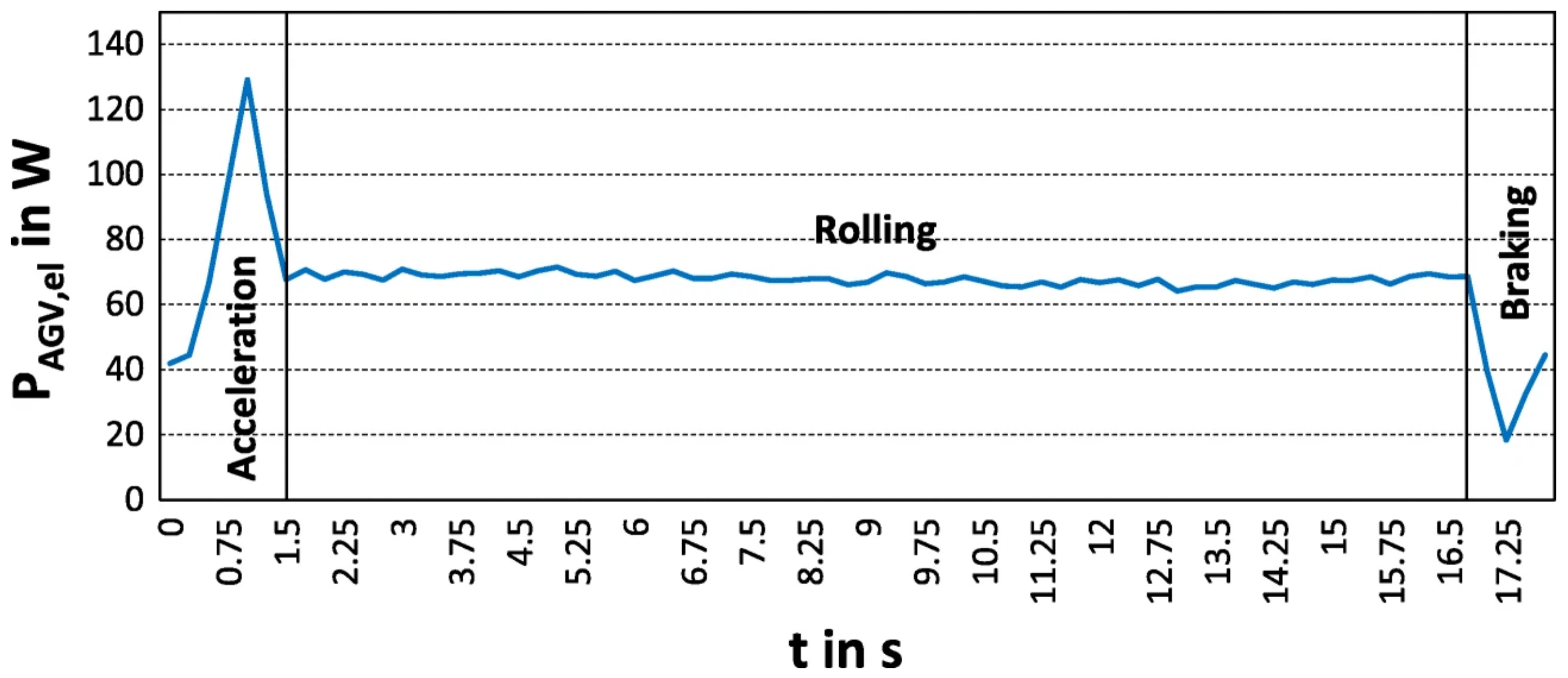
HESS are typically used for the power smoothing of power-sensitive applications, which are mentioned in several publications [18,21,22,23,24,25]. This is the case, for example, with vehicles during an acceleration process. Acceleration requires a higher power peak compared to constant velocity driving. (cf. Figure 2, ‘Acceleration/Rolling’).
In the case of higher power deceleration, regenerating more power than the overall demand, the regenerated excess power can be supplied back into an ESS (here assuming that the vehicle control requires 40W continuously, cf. Figure 2, ‘Braking’). These can be fed back into an ESS through targeted regenerative braking. Research by the Université de Sherbrooke Canada has shown that the effective current of the battery can be reduced by 12%, thus, making a positive contribution to the battery’s service life [18]. This effect has also been described in other studies [19,24].
The strategies for energy flow control in a HESS are usually rule-based. For example, if a load current demanded by the electrical load is greater than the maximum current of the battery, the SC is added. The same applies to a braking process with the opposite direction of current flow. To keep the SC ready for an acceleration process, the energy flow from the battery to the SC is switched as required [26].
Figure 2.
Example of required power of an AGV depending on the driving mode [27].
Figure 2.
Example of required power of an AGV depending on the driving mode [27].

2.5.2. Current Approaches to Dual Energy Storage Systems (DESS)
An approach for a DESS in an AGVS is provided by Bär Automation GmbH [28]. This procedure describes the application of two distinctive ESU, where the primary ESU is designed as a SC and the secondary ESU is designed as a battery. The primary goal of this approach is to guarantee the continued operation of the AGV after operational downtime. As already described in Section 2.2, the self-discharge of SC with 90%/d is very high.
After downtime, e.g., due to a weekend, the SC cannot supply enough electrical energy to the AGV to reach the next CS. The energy flow control is rule-based. The battery is kept at a constant state of charge during operation or successively charged after use. If the SC voltage falls below a lower threshold voltage, the battery is switched on as an energy supplier and the AGV can be supplied with energy until the next CS. The concept presented in this paper differs from the patent in that both ESUs (SC and battery) can be used as stand-alone energy supply depending on the transport distance.
The main aim is to increase the operational availability of the vehicles by using the SC as the primary ESU for short distances and the battery for long distances. The high power density of the SC enables fast charging at various load transfer stations, while some of the charged energy can be transferred from the SC to the battery while driving.
2.5.3. Circuit Concepts
Zimmermann et al. conducted a review of circuit concepts for the combining of high-power (i.e., SC) and high-energy (i.e., battery) storage units, where the collected papers were mainly written in the context of electric vehicles. Furthermore, based on the referenced investigations, they developed a topology class of “discrete hybrid energy storage topologies (HEST)” (i.e., circuit concepts). The following section shows two typical circuit concepts according to Zimmermann et al. and Cao et al. as well as two extensions [24,25,29,30]. Arrows are used to indicate which direction the energy flow can take place.
The first circuit concept “Capacitor semi-active HEST” (cf. Figure 3) is often the subject in studies on HESS (cf. [19,20,23,24,29]). A DC–DC converter was added between the battery and SC, with the battery directly connected to the DC link. Due to the bidirectional DC–DC converter, it is possible to actively connect or disconnect the SC for the supply of power peaks in the case of acceleration, as well as the regenerative braking energy into the SC. In addition, the DC–DC converter enables strict separation of the SC and battery voltages. A significantly larger voltage range of the SC can be used compared to the first circuit concept, which results in higher efficiency.
Xiang et al. developed a circuit concept for HESS in which only a DC–DC converter with a comparatively lower power rating than other circuit concepts is used (cf. Figure 4). Depending on the power requirement of the load, different switching states can be achieved using switches S1 and S2. The dashed connections refer to the unidirectional voltage balancing of the concept, where the SC voltage is always kept greater than or equal to the battery voltage. This allows a supporting energy flow from SC to the load.
The third circuit concept “Parallel full active HEST” (cf. Figure 5) is characterized by two DC–DC converters and strict separation of the two ESUs. Depending on the drives and the control method for the speed of a vehicle, it is typically necessary for the DC link to have a constant voltage. By separating the ESUs and the DC link by DC–DC converters, a constant DC link voltage can be ensured regardless of the state of charge of the ESUs. Depending on the design of the DC–DC converters, regnerated power from braking can be fed back into the SC or also into the battery.
Hanschek et al. have investigated topologies (i.e., circuit concepts) of HESS for use in AGVs. The basic circuit concepts can be derived from the previously mentioned circuit concepts by Zimmermann et al. and were partly extended by various concepts for voltage balancing of the common DC link.
Figure 6 shows a circuit concept from Hanschek et al., which, in addition to the topologies from Zimmermann et al. considers further electrical loads with different voltage levels (cf. “Control1” to “Control3”) in Figure 6), for example for load handling or control units. Here, the possible energy flows in the circuit concept are also illustrated through arrows. It can be derived directly from the circuit concept 3 “Parallel full active HEST” (cf. Figure 5).
2.5.4. Limitations of Current HESS for AGVs
The application of HESS in EVs as well as in DC grids is typically limited to smoothing power during operation. An investigation of the use of different energy storage types depending on the transport distance, especially for AGVS, has not been carried out thus far. Separation of the power supply of controls and drives by two ESUs has also not been considered in previous studies.
In most cases, AGVs are operated with electric motors, which are also the focus of this paper. Electrochemical or electrical ESS are used for this purpose. Depending on the type of ESS, different charging strategies are required, which have already been described in the Section 2.4.
The only objective of the concept of Bär Automation GmbH is that after an operational downtime the system continues to be supplied with energy and can continue to operate. With this system solution, it is not possible to switch between the ESS depending on the transport route. Likewise, a separation of the electrical loads is not provided, since the battery voltage is used directly as the supply voltage for the control and sensor systems (cf. [28]).
3. Concept of a DESS for AGV
In this section, the concept of a DESS is introduced, in which both used ESS can be used separately as an energy supply system for both the control and the drives. After the concept description, the control strategy is described, possible energy flows within a DESS are outlined and analyzed and then concepts for circuit implementation are presented.
3.1. Concept Description
To counteract the disadvantages of the respective energy storage solution for AGVs mentioned in Section 2.2, a concept of a DESS consisting of a battery module and an SC module was developed. In this concept, the electrical loads of the drive and the controls are considered separately. The ESS is selected based on the expected transport distance of the respective transport task. The two electrical loads are in the following illustrated separately to highlight the different energy flows in different situations.
The electric drives include motor controllers and the drive motors for moving. The control unit includes the power supply for sensors and control systems, as well as other electrical safety devices, such as warning sounders or indicators. Possible additional actuators and peripherals for load handling, such as lifting plates or conveyor rollers can be assigned to the control if required.
The process for a short distance consists of three steps (cf. Figure 7) and for a long distance without opportunity charging of five steps (cf. Figure 8). The upper part of the diagram shows the energy flow within the AGV, as well as from CS to SC. The green arrows describe the respective energy flows. The lower part shows the position of the AGV between two stations. An Arrow is used to indicate whether the AGV moves in the current step.
In the initial situation (step 1 in Figure 7) in a short-distance process between two stations with a CS the AGV is picking up goods and charging the SC at the first station. During charging, the CS is coupled directly to the SC, and the energy flows simultaneously into the SC and to the vehicle control through the converter of SC module. The SC remains selected as the power supply for the vehicle. In the second step, the SC supplies the vehicle control and drives as well as still charges the battery. Arriving at station B, the vehicle changes goods while the SC is charged by the CS as in step 1. In this step, the SC continuous to supply energy to the vehicle and charging the battery (step 3 in Figure 7).
For the long-distance process, it is assumed that the initial state of charge of the battery is sufficient for supplying the vehicle during the subsequent transport orders until a transport order includes a station with a CS. This process is exemplary for a transport between a station with charging system and a station without a charging system and back (A to C to A, cf. Figure 8).
At the station with a CS, the AGV picks up goods and charges the SC simultaneously. The CS supplies further the vehicle control and charges the battery. In the second process step, the AGV starts moving. The SC supplies the control and drives until the SC can no longer supply energy. At this point, the third process step begins, in which the battery takes over the power supply to the control and drives. The SC is always discharged first to ensure maximum energy absorption during the next charging process.
Arriving at station C (process step 4, cf. Figure 8), the vehicle hands over its goods and picks up new goods, while the battery supplies the vehicle control system with energy. In the last process step, the AGV relies on the battery as the sole energy supplier from the start of the journey, since the SC could not be charged at station C.
3.2. Conceived Control Strategy
The operating concept of AGVs with the application of DESS can be distinguished into the short-distance cycle and the long-distance cycle. Both cycles can be divided into different stages, stop, stop with transfer, stop with transfer and charging, stop with charging and without transfer and transport. The cycles start with the beginning of a transportation task with the stage “charge” and end with the completion of the transportation task until the next charging process.
During the short-distance cycle, the SC of the DESS is fully charged and supplies the vehicle control and the electric drives with energy during the driving task. At the same time, the SC storage unit releases energy continuously to the battery to supply it evenly with energy for improved service life. It is assumed that the maximum capacity of the SC storage unit is smaller than that of the battery.
Due to the high power density of the SC, it can absorb a lot of energy in a few minutes or seconds compared to the battery and can subsequently charge the battery successively during short-distance cycles, in order for the battery to provide energy for the vehicle during long-distance cycles. This sets a limit to the relative frequency of long-distance cycles to short-distance cycles and needs to be considered during the dimensioning of the storage.
At the goods transfer station, the SC storage unit of the DESS is recharged in a short time, such that it is ready for use again and is ready for use again immediately after the transfer of the conveyed goods. During the long-distance cycle, the battery must have a charge level with which a trip to the remote destination and a return trip can be performed regardless of whether the destination is equipped with a CS.
During the journey, the electric drives and the vehicle control system are supplied with electrical energy from a single ESU. If there is no CS at the destination point, the SC storage unit cannot be temporarily charged and the battery must provide the energy supply for the control system and drives alone during the next trip. At the next load transfer station with a charging system, the SC storage can be charged again in a short time. Depending on the battery’s state of charge and the demand for long-distance orders, the battery in the DESS is capable of handling further long-distance trips.
3.3. Energy Flow Analysis in a DESS for AGVs
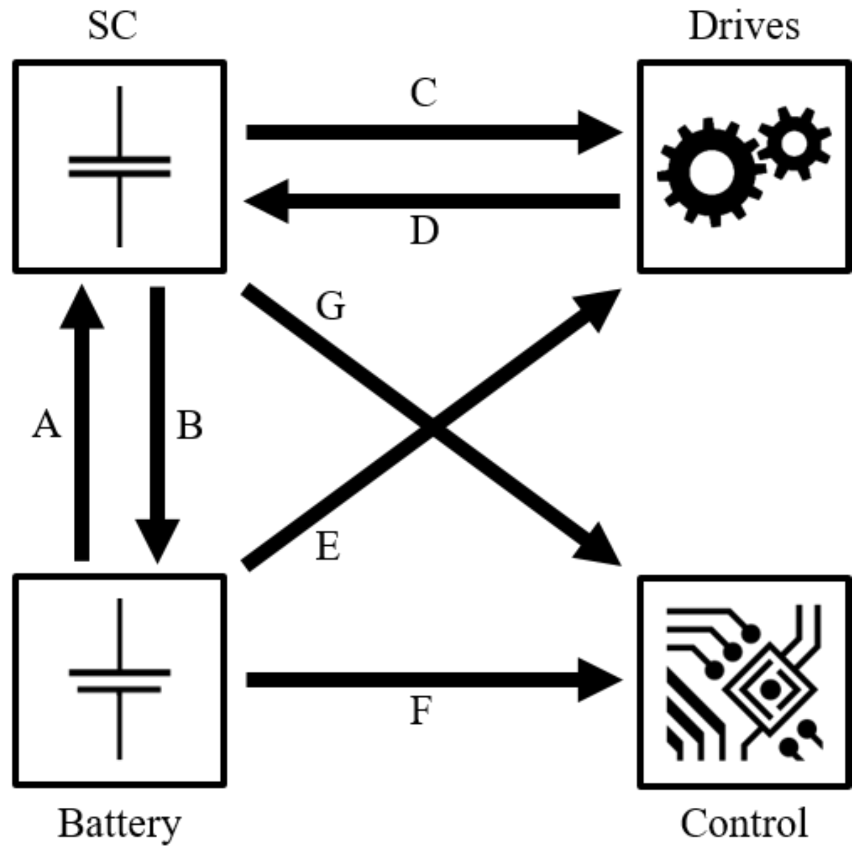
The following Figure 9 illustrates the previously described two different types of energy storage in a DESS and their connection to the drives and the control system. The possible energy flows within the system are marked with arrows. The division of the energy supply between the drives and the control system is intended to prevent voltage dips in acceleration phases, facilitate the recovery of braking energy from the drives into the SC module and enable the energy supply for the drives to be switched off completely.
To determine the necessary energy flows and their combinations for the DESS concept, the first step was to filter for physically possible ones. In the second step, combinations of energy flows were analyzed regarding efficient energy flow management. Subsequently, possible combinations of the energy flows were determined. Since the sequence or repetitions according to combinatorics are not relevant for the determination of the energy flow state combinations, the maximum number of possible combinations can be calculated as , with the number of possible energy flows with being .
Subsequently, criteria were worked out to exclude combinations of different energy flows. The column “Excluded combination” in Table 2 describes the combinations that does not apply to the DESS concept. The second column describes the exclusion criteria in detail. The upper part of the table defines the physically impossible, and the lower part of the table defines the combinations excluded due to other criteria.
The outcome are nine energy flow combinations and one charging state, referred to as energy flow states in the following Table 3. The charging state is comparable to the “StandbySC+”, whereby a power flow into the SC is also given.
The states are to be distinguished by operation mode and by used ESU. The first operation mode is ‘Standby’ in which the control unit is supplied with power and the drives remain voltage-free. The ‘drive’ mode describes states, in which the control unit and the drives are supplied with power from one of the two energy store units. The ‘RegBrake’ mode is the regenerative braking mode, where the control unit is supplied with power and simultaneously the regenerated power from the deceleration of the AGV will charge the SC.
These three modes can be found for each used ESU. States with designations ending ‘BAT’ uses the battery for supplying the AGV and is activated, when the SC is discharged. The states with designations ending ‘SC+’ and ‘SC’ are used as long as the SC is not discharged. Designations ending ‘SC+’ describes the state, where the battery is charged via the SC. This can take place during the three operation modes mentioned above.
The last energy flow state is the ‘ChargeSC’, which describes the energy flow during the charging process. While the SC is supplied with energy by the CS, the CS also supplies the control unit through the SC converter (cf. energy flow G) and simultaneously charges the battery (cf. energy flow B). Based on the selection of the energy flow states, a suitable circuit concept must be developed. This is explained in the following section.
3.4. Circuit Concept
In this section, three circuit concepts for use as DESS are presented and compared. Each converter mentioned in this section is a DC–DC converter. The requirement for each of the circuit concepts is that all energy flow states (cf. Table 3) are technically feasible. It must be noted that recuperation of braking energy into the SC, as well as separate energy supply of vehicle control and drives can be possible. If no recuperation is required, an omnidirectional converter can be used instead of a bidirectional converter to save costs.
Separating the electrical loads makes sense for several reasons. On the one hand, possible different voltage ranges can be realized, on the other hand, the input voltages to the various loads are, up to a point, decoupled of each other. Short-term power peaks drawn by one load do not cause drops in the input voltage of other loads. By using additional capacitors parallel to the power supply of the drives, the power peaks can be buffered to minimize the voltage drops such that the power supply of the vehicle control can be maintained.
For better comparability of the circuit concepts that are shown in Figure 3, Figure 4, Figure 5, Figure 6, the arrangement of SC, battery, drives and vehicle control is identical. The arrows indicate the possible energy flow with direction. In all concepts, the converters are designed as components that can be switched off. This enables targeted switching on and off. The following circuit concepts are essentially based on the ’multiple converter configuration’, according to [24] (cf. Figure 5).
3.4.1. Common Loadside Circuit Concept
The common loadside circuit concept (cf. Figure 10) can be distinguished from the “Parallel full active HEST” (cf. Figure 5 [29]) by a different arrangement of the converters. The converters DCDC1 and DCDC3, the input sides of which are directly connected to the SC or the battery, adjust the voltage of the respective ESU to the nominal voltage of the drives.
Only one of DCDC1 or DCDC3 is active at the same time in steady state. For feeding back energy from regenerative braking to the SC, DCDC1 is bidirectional. The drives and the input sides of the other converters DCDC2 and DCDC4 are connected to the common loadside DC-Link. DCDC2 regulates the constant output voltage of DCDC1 to the end-of-charge voltage of the battery when the system is supplied from the SC; otherwise, it is turned off and DCDC3 is active. To limit the charging current for the battery an additional circuit is required. DCDC4 regulates the constant output voltages of DCDC1 to the nominal voltage of the vehicle control.
The advantage in this concept is that only DCDC1 requires a large input voltage range. The other converters could be designed as lower-cost linear voltage regulators. However, this would result in low efficiency; thus, DC–DC switched mode converters would be preferable in terms of optimizing operating range. However, these converters do not need to support as wide of an input voltage range.
A disadvantage of this circuit concept is that, if converters are connected in series, the overall efficiency is lower than in the parallel circuit concept because the individual power losses are added up. Furthermore, it may only partially possible to use converters already installed in existing AGVs.
Regenerative braking can be supported, but DCDC1 needs to regulate the common DC-link voltage relatively tightly to avoid the voltage range from exceeding the allowed input range for DCDC2 or DCDC4. Otherwise regenerative braking cannot be supported. The selective disconnection of individual energy supplies by converters cannot always be guaranteed either. For example, if the control system is to be supplied with energy and the energy supply for the drives is to be switched off simultaneously, this would not be possible without a separate cut-off device in this circuit concept due to the series arrangement of the converters, regardless of the ESU used.
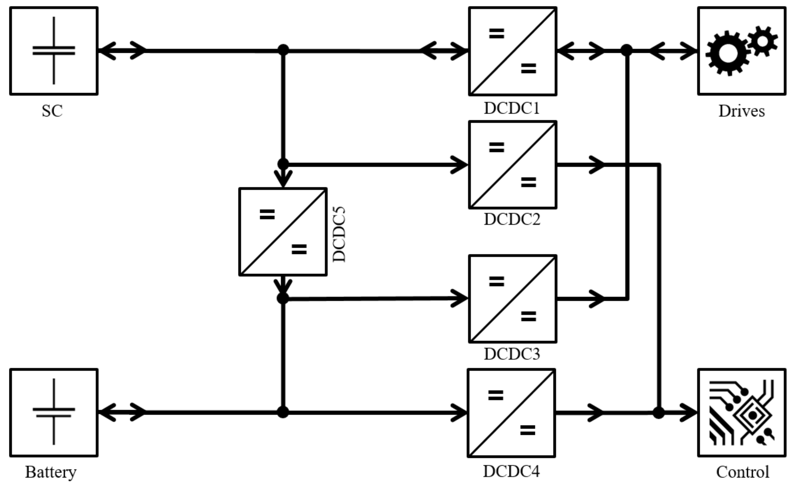
3.4.2. Parallel Circuit Concept
The parallel circuit concept (cf. Figure 11) includes five converters. DCDC1 is designed as a bidirectional converter, which allows energy flow from SC to the drives as well as vice versa for regenerative braking (cf. Figure 9, energy flows C and D). DCDC2 is responsible for supplying energy to the vehicle control through the SC, allowing energy flow G. DCDC3 is responsible for supplying energy to the drives through the battery (cf. energy flow E) whereby DCDC4 is responsible for the energy flow from battery to vehicle control and fulfills energy flow F. Finally, DCDC5 is used for matching the SC voltage to the battery voltage, which ensures the power flow B.
The converters arranged in parallel allow unneeded converters to be switched off to save power dissipation due to energy conversion. It allows the energy flow states defined in Table 3 to be controlled directly by switching the converter on or off. In steady state, only one of the pair DCDC1 and DCDC3, as well as one of the pair DCDC2 and DCDC4 is active. DCDC5 is only active in modes where the SC is used as a supply. The disadvantage in this concept is that the three converters connected directly to the SC (DCDC1, DCDC2 and DCDC5) require a wide voltage input range to maximize the energy yield of the SC. Converters with a wide voltage input range are more expensive compared to converters with smaller voltage input ranges.
3.4.3. Powerswitch Circuit Concept
Due to the previously mentioned disadvantages as well as the high number of investment-intensive converters of the parallel circuit concept and common loadside circuit concept, another circuit concept is necessary that requires fewer converters. In order to reach the respective voltage ranges of the drives and the vehicle controls, converters are already used in most AGVs. If these are already available (DCDC2 and DCDC3, cf. Figure 12), only one additional converter (DCDC1) and two switching devices (DCDC1, Switch1 and Switch2, cf. Figure 12) are required to implement the DESS with the powerswitch circuit concept. This concept does not require any intervention in the vehicle electrics.
Only the connections to the ESS need to be modified. The following circuit concept is named after the utilised switching devices. Both ESUs are connected in parallel via Switch1 and Switch2 to the converters DCDC2 and DCDC3 of the respective electric loads. Due to the different voltages of the ESUs, varying based on the energy storage type and state of charge, a direct parallel connection to the voltage supply of the converters through the changeover switch is to be avoided.
As required in Section 3.3, regenerative braking to the SC must be possible also during battery operation. This is enabled by switching the drives over to the SC during the braking. The converter between SC and battery shall be designed for voltage ranges of both ESUs. The direction of energy flow is restricted from the SC to the battery.
4. Results
This section presents the results of this paper. These are divided in three sections, the realization approach for the control strategy, the circuit concept analysis and the concept evaluation.
4.1. Realization Approach for the Control Strategy
In this section, an approach for realizing the conceived control strategy is presented where the control can be implemented in the form of a state machine. Figure 13 shows a state machine that can be derived from the conceived control strategy. For a simplified overview, the states for regenerative braking have been neglected here; however, the corresponding states would be placed between the “Drive” and “Standby” states. The start of the state machine was defined before the state ‘ChargeSC‘. It is assumed that a charge cycle runs long enough to increase the state of charge of the SC to at least 99%.
Then, depending on the fulfillment of the conditions, the state ‘DriveSC+’ or ‘DriveSC’ is activated. During a journey between two stations with CS, it is possible for the AGV to occasionally experience foreseen or unforeseen standstill times. Depending on the control input of the vehicle control (i.e., “cmdStop”, “cmdGo” and “cmdCharge”), it is possible to switch between the ‘Drive’ and ‘Standby’ state groups. It is assumed that the DC–DC converters or switches of the implemented circuit concept can be activated or deactivated by means of I/O signals.
To implement the state machine, the parameters described in Table 4 must be known.
represents the maximum amount of energy of the SC. The usable amount of energy of the SC depends on the voltage input range of the DC–DC converter used as these require a minimum voltage on the input side for voltage conversion. Voltages below this limit can no longer be converted to the set output voltage. The amount of energy thus remaining in the SC is subtracted from the maximum amount of energy of the SC to determine the usable amount of energy. This variable is calculated as follows:
describes the expected energy demand of the vehicle for a transport job until the next charging station. Average power requirements of the control unit and drives as well as onboard charging (cf. Energy flow B, Figure 9) are at least taken into account and calculated as follows:
Not considered for calculations at this time are aging processes, efficiencies of the DC–DC converters and potential power requirements for load handling and others. All variables are updated cyclically while operating.
The conditions “cmdStop”, “cmdGo” and “cmdCharge” are control inputs of the vehicle control unit. Depending on the control of the vehicle, the necessary DC–DC converters and switches are set according to the control concept. The results for the control of the three conveiced circuit concepts are presented in the following Section 4.2. The switching conditions of the state machine are defined based on the conceived control strategy (cf. Section 3.2) as follows:
- If the usable amount of energy in the SC can sustain the energy supply of the entire AGV during a transport distance to the next known CS and, at the same time, can supply the battery with energy for the scheduled transport duration.
- If the usable amount of energy in the SC to power the AGV cannot be maintained during the transport distance to the next known CS, or only if no additional energy is drawn from the SC to power the battery.
- When the SC voltage has reached or undershot the lower limit voltage , specified for example by the minimum input voltage of the DC–DC converter.
4.2. Circuit Concept Analysis
The circuit concepts presented in Section 2.5.3 were created with the background of the development of power trains in electric vehicles. In most cases, electrical devices for control or additional devices for automatic load handling, as used in several AGVs, were not considered. Nevertheless, some of these circuit concepts provide switching states for specific energy flows (cf. Section 3.3), which are necessary for the conceived control strategy presented in Section 3.2. For the evaluation of the developed circuit concepts (cf. Section 3.4.1), the circuit concepts are in the following compared and contrasted in tabular form and on the basis of several properties.
A comparison of the circuit concepts from related work and the concepts presented in this work is shown in Table 5. The upper four circuit concepts are the concepts presented in Section 2.5.3, and the lower three are the contributed circuit concepts from Section 3.4.1. For each circuit concept, the necessary amount of DC–DC converters and how many of them need to be bidirectional are shown.
Furthermore, the main ESU, as well as the type of energy distribution between the ESUs (i.e., “Onboard charging”) is contrasted. The main ESU is determined based on which is being primarily charged at a CS. The required charging time depends on the characteristics of the ESU and the CS, but the charging time can be qualitatively compared, as relatively high or low. As already presented in the Section 2.2, SC can be fully charged within a few seconds to minutes without a large negative impact on the lifetime.
For batteries, on the other hand, the charging time should be increased significantly for maximizing the lifetime [31,32]. Furthermore, heat losses during charging does not allow fast charging as in SC. Current limiting and temperature monitoring is required for all energy storage types.
The next two contrasted properties are whether the circuit designs support fully all presented regenerative braking states (cf. Table 3) while using battery as the power source for the controls and whether the control unit can be supplied separately from the drives. Finally, based on the properties, we evaluated whether the circuit concepts are applicable for the use of a DESS control strategy.
The top four circuit concepts all feature the battery (i.e., “BAT”) as the main ESU, suggesting a high charging time. Only the “CSA-HEST” and “Advanced CSA-HEST” concepts offer the possibility of power flow from SC to battery, which is part of the innovative core of the presented DESS control strategy. Due to the requirements expected by the control strategy for regenerative braking while the battery supplies the control unit and that the control unit can be supplied with energy separately from the drives, these circuit concepts are not possible without extensions or adaptations, for example by additional DC–DC converters or switching devices.
The “Common loadside” concept presented is also not fully suited for use with the DESS control strategy due to the limitations regarding regenerative braking while using battery as the ESU for the AGV, as well as the lack of separate supply of the control unit and drives (cf. Table 6 and related discussion below).
The contributed concepts “Parallel” and “Powerswitch” are applicable for the use of the presented DESS control strategy. In all concepts, the conditions for the energy flow from the SC to the battery are given, and the control unit and the drives can be supplied with energy separately. Furthermore, regenerative braking is supported without affecting the energy supply to the control unit.
The following Table 6, Table 7 and Table 8 show the mapping of energy flow states and active converters as well as the switch position with the “Powerswitch” concept. The mapping validates the concepts as being able to support the control strategy for using DESS. Bullets in the Tables indicate that the respective system component is active. “P” stands for the corresponding switch position, which are indicated in the figures of the respective circuit concepts. Finally, brackets indicate a possible problem.
The mapping of the common loadside concept has shown that all states except “RegBrakeBAT” can be used without further system adjustments. For the state “RegBrakeBAT” the activation of DCDC1, DCDC3 and DCDC4 is necessary, whereby DCDC1 is used in reverse. With this configuration DCDC1 is using the common DC-link as an input, while DCDC3 supplies the DC-link as an output, attempting to regulate it to a constant voltage.
This system state might lead to regulatory issues (leading, e.g., to input voltage fluctuations to the controls as the input to DCDC4 fluctuates), or undesired behavior (e.g., inefficiently charging SC from battery). These issues and possible solutions were not the focus of current work and will be investigated as part of future work.
In the mapping of the circuit concepts Parallel and Powerswitch, each state can be represented by an equivalent combination of switch positions of the DC–DC converter and switch devices. Regardless of the control strategy used, all circuit concepts require at least one bidirectional DC–DC converter. For further energy flows, additional DC–DC converters are required, which can usually be designed as unidirectional DC–DC converters.
In the case of the “Common loadside” concept, it is possible to reduce the required count by one by combining DCDC2 and DCDC3 into one bidirectional DC–DC converter (cf. Figure 10). For the “Advanced CSA-HEST” and “Powerswitch” concepts, two circuit devices are required in addition to the DC–DC converters. The operation of these is described in Section 2.5.3 and Section 3.4.1.
4.3. Concept Evaluation
According to Woody et al. [31] and Xie et al. [32], it is assumed that by charging the battery by the SC during some states of the control strategy (cf. Table 3, especially when driving short distances, that the battery lifetime in the DESS can be increased compared to state-of-the-art system solutions. It is assumed also that the average depth of discharge (DoD) of the battery in the DESS does not exceed 50%.
According to Woody et al. [31] and Hua et al. [33], it is concluded that the battery lifetime can be further increased by reducing the average DoD. The use of two stand-alone ESUs allows the AGV to rely on the respective ESU as the sole power supply system, depending on the planned power demand to the next charging station. The goal of this concept with a DESS, as explained at the beginning, is to dimension the ESUs for a specific application with a minimum required capacity.
SC as a sole energy supply system has the disadvantage of being a very expensive solution with typical gravimetric energy densities of 4 Wh/kg to 9 Wh/kg and acquisition costs of 5 €/kWh to 12 €/kWh. Batteries, on the other hand, offer a comparatively short lifetime with a cyclic lifetime of 200 to 8000, which is further reduced by fast charging (cf. Table 1) [31,32]. The ability to fast-charge the SC at load transfer stations is assumed to provide high AGV operational availability compared to battery-powered AGVs.
Compared to AGVs with SC as the sole energy storage device, a higher operational availability of the AGV is expected, since an AGV with DESS requires fewer charging cycles when considering a larger period of several hours. This can be justified by the intermittent use of the battery in the DESS, which, however, does not require a charging cycle at a charging station. The aforementioned expectations in terms of charging time and increase in operational availability only apply if opportunities for charging the SC are also available at several of the AGV load transfer stations.
When designing the battery for the DESS, it is expected that at least 90 % of the required capacity for a 16 h operation can be saved by an equivalent battery-powered AGV, thus contributing to the resource efficiency of AGVs. The disadvantage of this concept is the higher complexity in the development and integration in AGV. By adding another control unit for energy management in the DESS, which requires further interfaces with the vehicle control system, the development is more complex than typical energy storage systems. Furthermore, for the integration of DESS in AGVs, adjustments in the transport layout regarding CS may have to be made.
5. Conclusions
In this paper, we presented a control strategy for an AGV using a DESS. An energy management system, which takes over the control strategy, regulates the energy flows between the DESS components, CS, the vehicle control, the drives and the used ESUs. The use of a DESS in an AGV pursues the goal of achieving at least the same operational availability of the vehicles as compared to the current state of the art with the minimum necessary energy storage capacity.
The control strategy states that, depending on the transport distance of the current transport job, either the SC or the battery can be used as the sole energy supply for the vehicle. In addition to the concept of the control strategy, circuit concepts were presented with which the functional concept of the DESS can be implemented in AGVs. The functionality of the three conceived circuit concepts was validated by the mapping of energy flow states and active converters. Furthermore, a requirements analysis of energy flow combinations within the AGV was carried out in order to derive possible process states. A further result of this paper, a realization approach for implementing the control strategy in the form of a state machine was presented.
The control concept of AGVs with a DESS requires further investigation, particularly on the subject of design procedures. Common design methods cannot be applied for the dimensioning of the DESS. On the one hand, they mostly consider energy storage systems with one ESU only, on the other hand, they do not take into account the dimensioning of the required circuit components for energy management, which is based on one of the circuit concepts presented in this paper.
As further future work, the effects of the DESS-concept on both the AGVS level and vehicle level can be further studied. On the AGVS level, e.g., the optimization of transport layouts or task management for DESS based AGVs to further improve energy efficiency or to combine with other optimization goals, such as the system availability or minimizing the required charging infrastructure are interesting open questions. On the vehicle level, as noted, e.g., by [34,35], the optimization of driving strategies for energy efficiency can have an effect on the dimensioning of the whole powertrain. Thus, another interesting research direction is the optimization driving strategies alongside the DESS concept and the possible effects on the dimensioning of the powertrain.
The contents of this paper provide the basis for a related empirical investigation using simulations. In a subsequent paper, a design procedure for dimensioning a DESS for AGVs considering vehicle specifications and material flow data is presented. Furthermore, the control concept is presented in the form of a simulation, and its results are compared with control strategies and their ESS from the state of the art.
6. Patents
A patent is pending for the energy storage concept presented in this paper.
Author Contributions
Conceptualization, M.S. and T.K.; methodology, M.S.; formal analysis, M.S.; investigation, M.S.; writing—original draft preparation, M.S.; writing—review and editing, M.S. and T.K.; visualization, M.S.; project administration, M.S.; funding acquisition, M.S. All authors have read and agreed to the published version of the manuscript.
Funding
This research was funded by the German Federal Ministry for Economic Affairs and Energy under the grant number KK5040304ZG0.
Institutional Review Board Statement
Not applicable.
Informed Consent Statement
Not applicable.
Data Availability Statement
Not applicable.
Acknowledgments
We acknowledge support from the KIT-Publication Fund of the Karlsruhe Institute of Technology.
Conflicts of Interest
The authors declare no conflict of interest.
Abbreviations
The following abbreviations are used in this manuscript:
| AGV | Automated guided vehicle |
| AGVS | Automated guided vehicle system |
| CS | Charging system |
| CSA | Capacitor semi-active |
| DC–DC | DC–DC-converter |
| DESS | Dual energy storage system |
| EDLC | Electric double-layer capacitor |
| ESS | Energy storage system |
| ESU | Energy storage unit |
| HESS | Hybrid energy storage system |
| HEST | Hybrid energy storage topologies |
| LTO | Lithium titanate oxide accumulator |
| PFA | Parallel full active |
| SC | Supercapacitor |
References
- IFR International Federation of Robotics; World Robotics: Frankfurt, Germany, 2021.
- Holze, R. Elektrische Energie: Speichern und Wandeln; Essentials; Springer Fachmedien Wiesbaden GmbH and Springer Spektrum: Wiesbaden, Germany, 2019. [Google Scholar]
- Ullrich, G. Automated Guided Vehicle Systems: A Primer with Practical Applications; Springer: Berlin/Heidelberg, Germany, 2015. [Google Scholar] [CrossRef]
- Castelvecchi, D. Electric cars and batteries: How will the world produce enough? Nature 2021, 596, 336–339. [Google Scholar] [CrossRef] [PubMed]
- Horn, M.; MacLeod, J.; Liu, M.; Webb, J.; Motta, N. Supercapacitors: A new source of power for electric cars? Econ. Anal. Policy 2019, 61, 93–103. [Google Scholar] [CrossRef] [Green Version]
- Sauer, D.U.; Kowal, J.; Willenberg, L.; Rahe, C.; Teuber, M.; Drillkens, J.; Ringbeck, D.; Schäper, C. Speicherung der Elektrischen Energie; Tschöke, H., Gutzmer, P., Pfund, T., Eds.; Springer Vieweg: Berlin/Heidelberg, Germany, 2019. [Google Scholar]
- Kowal, J.; Avaroglu, E.; Chamekh, F.; Šenfelds, A.; Thien, T.; Wijaya, D.; Sauer, D.U. Detailed analysis of the self-discharge of supercapacitors. J. Power Sources 2011, 196, 573–579. [Google Scholar] [CrossRef]
- Kurzweil, P.; Dietlmeier, O. Elektrochemische Speicher: Superkondensatoren, Batterien, Elektrolyse-Wasserstoff, Rechtliche Rahmenbedingungen; Springer Vieweg: Wiesbaden, Germany, 2018. [Google Scholar] [CrossRef]
- Omar, N.; Gualous, H.; Salminen, J.; Mulder, G.; Samba, A.; Firouz, Y.; Monem, M.A.; van den Bossche, P.; van Mierlo, J. Electrical double-layer capacitors: Evaluation of ageing phenomena during cycle life testing. J. Appl. Electrochem. 2014, 44, 509–522. [Google Scholar] [CrossRef]
- Xu, G.; Han, P.; Dong, S.; Liu, H.; Cui, G.; Chen, L. Li4Ti5O12-based energy conversion and storage systems: Status and prospects. Coord. Chem. Rev. 2017, 343, 139–184. [Google Scholar] [CrossRef]
- Wu, K.; Yang, J.; Zhang, Y.; Wang, C.; Wang, D. Investigation on Li4Ti5O12 batteries developed for hybrid electric vehicle. J. Appl. Electrochem. 2012, 42, 989–995. [Google Scholar] [CrossRef]
- Huggins, R.A. Energy Storage: Fundamentals, Materials and Applications; Engineering; Springer: Berlin/Heidelberg, Germany; New York, NY, USA; Dordrecht, The Netherlands; London, UK, 2016. [Google Scholar] [CrossRef]
- VDI Society Production and Logistics. VDI 4451 Part 7: Compatibility of Automated Guided Vehicle Systems (AGVS)—AGVS Guidance Control System; VDI Society Production and Logistics: Düsseldorf, Germany, 2005. [Google Scholar]
- Colling, D.; Oehler, J.; Furmans, K. Battery Charging Strategies for AGV Systems. Logist. J. Proc. 2019, 2019. [Google Scholar] [CrossRef]
- VDI Society Production and Logistics. VDI 4451 Part 2: Compatibility of Automated Guided Vehicle Systems (AGVS)—Power Supply and Charging Technology; VDI Society Production and Logistics: Düsseldorf, Germany, 2000. [Google Scholar]
- Pagani, P.; Colling, D.; Furmans, K. A Neural Network-Based Algorithm with Genetic Training for a Combined Job and Energy Management for AGVs. Logist. J. Proc. 2018, 2018. [Google Scholar] [CrossRef]
- Zhan, X.; Xu, L.; Zhang, J.; Li, A. Study on AGVs battery charging strategy for improving utilization. Procedia CIRP 2019, 81, 558–563. [Google Scholar] [CrossRef]
- Trovao, J.P.F.; Roux, M.; Ménard, E.; Dubois, M.R. Energy- and Power-Split Management of Dual Energy Storage System for a Three-Wheel Electric Vehicle. IEEE Trans. Veh. Technol. 2017, 66, 5540–5550. [Google Scholar] [CrossRef]
- Gomozov, O.; Trovao, J.P.F.; Kestelyn, X.; Dubois, M.R. Adaptive Energy Management System Based on a Real-Time Model Predictive Control With Nonuniform Sampling Time for Multiple Energy Storage Electric Vehicle. IEEE Trans. Veh. Technol. 2017, 66, 5520–5530. [Google Scholar] [CrossRef]
- Pisu, P.; Rizzoni, G. A supervisory control strategy for series hybrid electric vehicles with two energy storage systems. In Proceedings of the 2005 IEEE Vehicle Power and Propulsion Conference, Chicago, IL, USA, 7–9 September 2005. [Google Scholar] [CrossRef]
- Mamen, A.; Supatti, U. A survey of hybrid energy storage systems applied for intermittent renewable energy systems. In Proceedings of the 2017 14th International Conference on Electrical Engineering/Electronics, Computer, Telecommunications and Information Technology (ECTI-CON), Phuket, Thailand, 27–30 June 2017; pp. 729–732. [Google Scholar] [CrossRef]
- Kouchachvili, L.; Yaïci, W.; Entchev, E. Hybrid battery/supercapacitor energy storage system for the electric vehicles. J. Power Sources 2018, 374, 237–248. [Google Scholar] [CrossRef]
- Liu, X.; Zhang, Q.; Zhu, C. Design of battery and ultracapacitor multiple energy storage in hybrid electric vehicle. In Proceedings of the 2009 IEEE Vehicle Power and Propulsion Conference, Dearborn, MI, USA, 7–10 September 2009; pp. 1395–1398. [Google Scholar] [CrossRef]
- Cao, J.; Emadi, A. A New Battery/UltraCapacitor Hybrid Energy Storage System for Electric, Hybrid, and Plug-In Hybrid Electric Vehicles. IEEE Trans. Power Electron. 2012, 27, 122–132. [Google Scholar] [CrossRef]
- Hanschek, A.J.; Bouvier, Y.E.; Jesacher, E.; Grbović, P.J. Analysis of power distribution systems based on low-voltage DC/DC power supplies for automated guided vehicles (AGV). In Proceedings of the 2021 21st International Symposium on Power Electronics (Ee), Novi Sad, Serbia, 27–30 October 2021; pp. 1–6. [Google Scholar] [CrossRef]
- Gokce, K.; Ozdemir, A. A Rule Based Power Split Strategy for Battery/Ultracapacitor Energy Storage Systems in Hybrid Electric Vehicles. Int. J. Electrochem. Sci. 2016, 11, 1228–1246. [Google Scholar]
- Meißner, M.; Massalski, L. Modeling the electrical power and energy consumption of automated guided vehicles to improve the energy efficiency of production systems. Int. J. Adv. Manuf. Technol. 2020, 110, 481–498. [Google Scholar] [CrossRef]
- Bär, R. Method for Operating an Automated Guided, Mobile Assembly and/or Material Transport Unit and Automated Guided, Mobile Assembly and/or Material Transport Unit Therefor. WO Patent 2010118737A2, 16 April 2010. [Google Scholar]
- Zimmermann, T.; Keil, P.; Hofmann, M.; Horsche, M.F.; Pichlmaier, S.; Jossen, A. Review of system topologies for hybrid electrical energy storage systems. J. Energy Storage 2016, 8, 78–90. [Google Scholar] [CrossRef]
- Xiang, C.; Wang, Y.; Hu, S.; Wang, W. A New Topology and Control Strategy for a Hybrid Battery-Ultracapacitor Energy Storage System. Energies 2014, 7, 2874–2896. [Google Scholar] [CrossRef] [Green Version]
- Woody, M.; Arbabzadeh, M.; Lewis, G.M.; Keoleian, G.A.; Stefanopoulou, A. Strategies to limit degradation and maximize Li-ion battery service lifetime—Critical review and guidance for stakeholders. J. Energy Storage 2020, 28, 101231. [Google Scholar] [CrossRef]
- Xie, W.; Liu, X.; He, R.; Li, Y.; Gao, X.; Li, X.; Peng, Z.; Feng, S.; Feng, X.; Yang, S. Challenges and opportunities toward fast-charging of lithium-ion batteries. J. Energy Storage 2020, 32, 101837. [Google Scholar] [CrossRef]
- Hua, Y.; Zhou, S.; Cui, H.; Liu, X.; Zhang, C.; Xu, X.; Ling, H.; Yang, S. A comprehensive review on inconsistency and equalization technology of lithium-ion battery for electric vehicles. Int. J. Energy Res. 2020, 44, 11059–11087. [Google Scholar] [CrossRef]
- Koch, A.; Teichert, O.; Kalt, S.; Ongel, A.; Lienkamp, M. Powertrain Optimization for Electric Buses under Optimal Energy-Efficient Driving. Energies 2020, 13, 6451. [Google Scholar] [CrossRef]
- Anselma, P.G. Optimization-Driven Powertrain-Oriented Adaptive Cruise Control to Improve Energy Saving and Passenger Comfort. Energies 2021, 14, 2897. [Google Scholar] [CrossRef]
Figure 1.
Block diagram of an AGVS and its components.

Figure 3.
Circuit concept 1 “Capacitor semi-active HEST”. Own illustration according to [29].
Figure 3.
Circuit concept 1 “Capacitor semi-active HEST”. Own illustration according to [29].

Figure 4.
Circuit concept 2 “Advanced Capacitor semi-active HEST”. Own illustration according to [29,30].

Figure 5.
Circuit concept 3 “Parallel full active HEST”. Own illustration according to [29].
Figure 5.
Circuit concept 3 “Parallel full active HEST”. Own illustration according to [29].

Figure 6.
Circuit concept 4 “Advanced parallel full active HEST”. Own illustration according to [25].
Figure 6.
Circuit concept 4 “Advanced parallel full active HEST”. Own illustration according to [25].

Figure 7.
Possible process for a short distance.

Figure 8.
Possible process for a long distance without opportunity charging at station C.

Figure 9.
Overview of energy flows in an AGV with a DESS. The flows B, C, D, and G are from the SC respectively to battery (charging), drives (motoring and regenerative operation) and controls. The flows A, E, and F are from the battery respectively to SC, drives and controls.
Figure 9.
Overview of energy flows in an AGV with a DESS. The flows B, C, D, and G are from the SC respectively to battery (charging), drives (motoring and regenerative operation) and controls. The flows A, E, and F are from the battery respectively to SC, drives and controls.

Figure 10.
Common loadside circuit concept.

Figure 11.
Parallel circuit concept.

Figure 12.
Powerswitch circuit concept.

Figure 13.
Derived state machine for realization of the control strategy.


| Energy Storage System | Acquisition Costs [€kWh] | Gravimetric Energy Density [Wh/kg] | Gravimetric Power Density [W/kg] | Cycle Life |
|---|---|---|---|---|
| Lead-acid | 100 | 25–40 | 100–500 | 200–300 |
| Li-Ion | 300–500 | 120–200 | 400 | 500–1000 |
| LTO | 300–400 | 70–80 | 2800 | 8000 |
| EDLC | 5000–12,000 | 4–9 | 1000–50,000 | 1,000,000 |
Table 2.
Excluded energy flow combinations.
| Excluded Combination | Exclusion Criteria |
|---|---|
| These combinations shows contrary energy flows at the same time. This is not physically feasible and is therefore excluded. | |
| Combining the energy flows from the battery and SC for the drives cannot be used in “powerswitch circuit concept” (cf. Section 3.4.3) due to different voltage ranges. The combinations can in theory be supported by the other suggested circuit concepts but are utilized at most briefly during transfer from one ESU to another. | |
| A | In the described functional concept of a DESS, an energy flow from battery into SC is not utilized. Furthermore, this is not feasible for the “powerswitch circuit concept” due to technical limitations (cf. Section 3.4.3). |
| The combination of the energy flows from the SC to the battery and from the battery to the drives and vehicle control are excluded to avoid efficiency drops due to the additional energy conversion to the battery. It can be ensured by the respective energy flow from SC to the drives [C] and from SC and the control [G]. | |
| The combination of the energy flow from one ESU to one load and simultaneously from the other ESU to the other load cannot be used beneficially (due to the losses during the previous energy transfer from one ESU to another) in this concept. Either the SC or the battery is used as the sole energy supplier for control and drives. | |
| It is assumed that at constant power demand in any operating state, power is supplied either by the battery or by the SC. Both energy flows are not possible simultaneously with the “powerswitch circuit concept” (cf. Section 3.4.3). |
Table 3.
Energy flow states. • indicates that the DC-DC-converter is active in the state.
| No. | B | C | D | E | F | G | State Designation |
|---|---|---|---|---|---|---|---|
| 0 | • | • | ChargeSC | ||||
| 1 | • | • | StandbySC+ | ||||
| 2 | • | StandbySC | |||||
| 3 | • | StandbyBAT | |||||
| 4 | • | • | • | DriveSC+ | |||
| 5 | • | • | DriveSC | ||||
| 6 | • | • | DriveBAT | ||||
| 7 | • | • | • | RegBrakeSC+ | |||
| 8 | • | • | RegBrakeSC | ||||
| 9 | • | • | RegBrakeBAT |
Table 4.
Input parameters for the state machine.
| Parameter | Description |
|---|---|
| Current voltage of the SC | |
| Nominal voltage for the SC | |
| Nominal capacity of the SC | |
| Lower voltage limit from the DC–DC converter connected to the SC | |
| Average power demand of the drives | |
| Average power demand of the vehicle control unit | |
| Average power demand for onboard charging the battery through the SC | |
| Estimated operation time to the next charging station |
Table 5.
Circuit concept comparison. if DCDC2 and DCDC3 are replaced by a common bidirectional DC–DC converter. if function “Regenerative braking while BAT supplies control unit” is not necessary.
Table 5.
Circuit concept comparison. if DCDC2 and DCDC3 are replaced by a common bidirectional DC–DC converter. if function “Regenerative braking while BAT supplies control unit” is not necessary.
| Circuit Concept | Count of DCDC| of Which Bidirectional | Main ESU | Onboard Charging | Charging Time | Regenerative Braking while BAT Supplies Control Unit | Control Unit Supplied Separately from Drives | DESS Control Strategy Applicable | |
|---|---|---|---|---|---|---|---|---|
| Related work concepts | CSA-HEST (cf. Figure 3) | 1|1 | BAT | SC <–> BAT | high | No | No | No |
| Advanced CSA-HEST (cf. Figure 4) | 1|1 | BAT | SC <–> BAT | high | No | No | No | |
| PFA-HEST (cf. Figure 5) | 2|1 | BAT | BAT –> SC | high | No | No | No | |
| Advanced PFA-HEST (cf. Figure 6) | 3|1 | BAT | BAT –> SC | high | No | No | No | |
| Contributed concepts | Common loadside (cf. Figure 10) | 4|1 or 3|2 | SC | SC –> BAT | low | No | No | Yes |
| Parallel (cf. Figure 11) | 5|1 | SC | SC –> BAT | low | Yes | Yes | Yes | |
| Powerswitch (cf. Figure 12) | 3|1 | SC | SC –> BAT | low | Yes | Yes | Yes |
Table 6.
Mapping of the energy flow states and active converters for the common loadside concept. • indicates that the DC-DC-converter is active in the state, while indicates the converter is operating in regenerative mode.
Table 6.
Mapping of the energy flow states and active converters for the common loadside concept. • indicates that the DC-DC-converter is active in the state, while indicates the converter is operating in regenerative mode.
| State | DCDC1 | DCDC2 | DCDC3 | DCDC4 |
|---|---|---|---|---|
| ChargeSC | • | • | • | |
| StandbySC+ | • | • | • | |
| StandbySC | • | • | ||
| StandbyBAT | • | • | ||
| DriveSC+ | • | • | • | |
| DriveSC | • | • | ||
| DriveBAT | • | • | ||
| RegBrakeSC+ | • | • | ||
| RegBrakeSC | • | |||
| RegBrakeBAT | (•) | • |
Table 7.
Mapping of the energy flow states and active converters for the parallel circuit concept. • indicates that the DC-DC-converter is active in the state, while indicates the converter is operating in regenerative mode.
Table 7.
Mapping of the energy flow states and active converters for the parallel circuit concept. • indicates that the DC-DC-converter is active in the state, while indicates the converter is operating in regenerative mode.
| State | DCDC1 | DCDC2 | DCDC3 | DCDC4 | DCDC5 |
|---|---|---|---|---|---|
| ChargeSC | • | • | |||
| StandbySC+ | • | • | |||
| StandbySC | • | ||||
| StandbyBAT | • | ||||
| DriveSC+ | • | • | • | ||
| DriveSC | • | • | |||
| DriveBAT | • | • | |||
| RegBrakeSC+ | • | • | |||
| RegBrakeSC | • | ||||
| RegBrakeBAT | • | • |
Table 8.
Mapping of the energy flow states and active converters for the Powerswitch concept. The switching state is not relevant for this condition as the load (DCDC1) is deactivated. • indicates that the DC-DC-converter is active in the state, while indicates the converter is operating in regenerative mode.
| State | DCDC1 | DCDC2 | DCDC3 | Switch1 | Switch2 |
|---|---|---|---|---|---|
| ChargeSC | • | • | N.A. | P1 | |
| StandbySC+ | • | • | N.A. | P1 | |
| StandbySC | • | N.A. | P1 | ||
| StandbyBAT | • | N.A. | P2 | ||
| DriveSC+ | • | • | • | P1 | P1 |
| DriveSC | • | • | P1 | P1 | |
| DriveBAT | • | • | P2 | P2 | |
| RegBrakeSC+ | • | • | P1 | P1 | |
| RegBrakeSC | • | P1 | P1 | ||
| RegBrakeBAT | • | P1 | P2 |
Publisher’s Note: MDPI stays neutral with regard to jurisdictional claims in published maps and institutional affiliations. |
© 2022 by the authors. Licensee MDPI, Basel, Switzerland. This article is an open access article distributed under the terms and conditions of the Creative Commons Attribution (CC BY) license (https://creativecommons.org/licenses/by/4.0/).
Share and Cite
MDPI and ACS Style
Sperling, M.; Kivelä, T. Concept of a Dual Energy Storage System for Sustainable Energy Supply of Automated Guided Vehicles. Energies 2022, 15, 479. https://0-doi-org.brum.beds.ac.uk/10.3390/en15020479
AMA Style
Sperling M, Kivelä T. Concept of a Dual Energy Storage System for Sustainable Energy Supply of Automated Guided Vehicles. Energies. 2022; 15(2):479. https://0-doi-org.brum.beds.ac.uk/10.3390/en15020479
Chicago/Turabian StyleSperling, Marvin, and Tommi Kivelä. 2022. "Concept of a Dual Energy Storage System for Sustainable Energy Supply of Automated Guided Vehicles" Energies 15, no. 2: 479. https://0-doi-org.brum.beds.ac.uk/10.3390/en15020479
Note that from the first issue of 2016, this journal uses article numbers instead of page numbers. See further details here.