1. Introduction
Nuclear power technology has been continuously researched and developed since its beginnings in the 1940s. Nuclear reactors are most often used to produce electric power, for which the demand increases every year; currently light water reactors (LWR) (~1000 MWe) dominate electricity generation. However, in recent years there have been more and more examples of uses of the process or waste heat generated by nuclear power in other processes, such as desalination of sea water to produce fresh water or district heating. The use of nuclear power plants (NPPs) operated in cogeneration results in many environmental, economic and efficiency related benefits. However, the thermal energy from LWR can be used only in selected branches of industry, where high temperatures are not necessary. In other industries, like chemical, metallurgical, etc., that need higher temperatures the employment of more advanced reactor technologies, like gas-cooled high temperature reactors (HTGRs) or high temperature reactors (VHTGRs), is reasonable. HTGRs belong to the Gen IV group of reactors that are characterized by efficient production of energy and providing the process heat at high temperatures that are used in many industrial processes, e.g., in the petrochemical and steel industry and for hydrogen production [
1,
2].
A serious issue related to the development of nuclear energy and the construction of new nuclear reactors is the still existing fear of nuclear power and its effects. Typical reasons for concerns are related to safety aspects, the radioactive pollution risk, high investment costs, and the production of high-level activity nuclear waste that creates a threat for many millions of years. These concerns have increased after the Fukushima Daiichi accident in 2011 [
3]. Certain countries, under pressure of public opinion, have decided to permanently suspend all activities related to nuclear power. Some of them, such as Switzerland, have decided not to renew licenses at the end of the nuclear power plant lifetime [
4], others, like Germany, have decided to do this more immediately [
5]. However, there are countries, like China, that are planning to develop their nuclear power plants [
6] or countries, like France, that have decided to continue the operation of nuclear power plants but also increase the share of renewable energies at the same time [
7]. It is worth noting that current technologies have significantly improved in terms of safety, economic and environmental impact. HTGRs are reactors that are characterized by efficient energy production and high temperature process heat supply [
1,
2]. Interest in high temperature gas cooled reactors has been growing dynamically in recent years. Around the world, the technology is accepted as an inherently safe nuclear reactor that is able to produce electricity with high efficiency and provide a high temperature chemical process for nuclear hydrogen generation. Deep burning of the long-lived actinides and plutonium in HTGRs is important in reducing the toxicity and the amount of generated waste [
8,
9].
In many countries, HTGRs with TRISO coated particle fuel are being deliberated for proximate term deployment. Poland is a country that is considering launching the HTGR technology for supporting domestic industries and achieving climate goals [
10].
The basic condition for the implementation of HTGR technology is to ensure constant supplies of TRISO fuel or to launch a production line in the country.
Another problem to solve is handling this unusual fuel after it is discharged from the reactor. The operation of nuclear reactors is always associated with the formation in their core through nuclear reactions of new radioactive compounds and materials, which are treated as waste that should be properly managed. Because of this, waste management is one of key matters to solve in nuclear energy. Advanced technologies that are now being researched will most likely help to solve this problem [
11].
Although direct disposal [
12] seems to be the most reasonable option for TRISO spent fuel, conducting studies on reprocessing seems important, given the economic and environmental determinants of the future and circular economy requiring the recovery of nuclear resources and reducing the amount of disposed waste. Safety of the operation of high-temperature reactors with the use of the new TRISO fuel is crucial for the implementation of HTGR technology and its further dissemination. It should also be noted that the use of TRISO fuels in many other nuclear reactors was considered, including light water, salt-cooled, microreactors and nuclear thermal propulsion [
13].
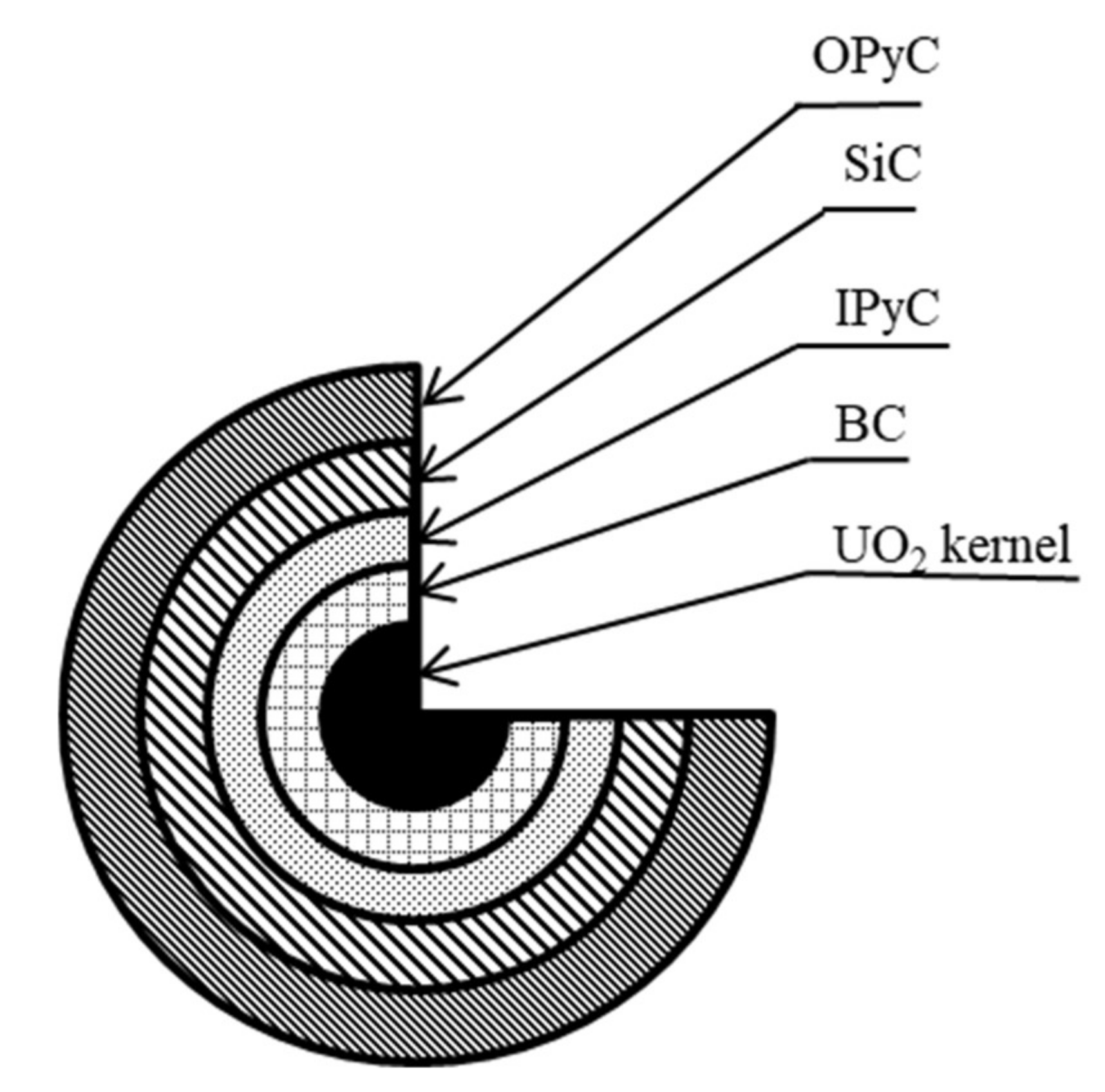
In recent times, it was confirmed that no fuel damage would occur, even during accidents, such as multiple losses of reactor shutdown functions. Each spherical fuel element contains about 8300 UO
2 particles coated with graphite layers. A UO
2 single particle is 0.92 mm in diameter and the fuel element is 60 mm in its outer diameter and 50 mm in its inner diameter [
14]. A UO
2 kernel is covered with four coatings: the porous carbon buffer layer (BC), inner coat of dense pyrolytic carbon layer (IPyC), coat made of silicon carbide (SiC) or zirconium carbide (ZrC) and outer dense pyrolytic carbon layer (OPyC) (
Figure 1). There are formed gaseous and metallic fission products during the operation of the reactor. The function of coating layers is to keep them in a fuel particle. The first coating, BC, is designed to collect gaseous fission products and carbon monoxide. The SiC coating is characterized by high mechanical resistance. It guarantees the high level of safety of TRISO fuel. SiC (or ZrC) ensures retention of gaseous and metallic fission products. The role of the outer pyrocarbon layer is a mechanical protection of cover layers. The structure of TRISO fuel and the materials used make it resistant to incidents that are dangerous when using traditional fuel and fuel rods, such as thermal expansion, pressure of fission products and temperatures above 1600 °C. The fuel design allows the reaching of high burnup and ensures a complete containment of all gaseous fission products in any normal or anomalous case of reactor operation.
The form and structure of the fuel determines the approach to handling it after burnout and discharge from the reactor.
2. The Types of Waste Generated in HTGR Cycle
During the operation and maintenance of nuclear power plants, radioactive waste with a broad range of characteristics is produced. This waste exists in various forms: gaseous, aqueous and solid, including the graphite moderator blocks, as well as the spent nuclear fuel (if disposal in deep repository is chosen). If the option of separation of fissile elements from spent fuel is selected, we deal with the additional waste generated along the reprocessing scheme. Each potentially radioactive product—gas, liquid or solid—is picked up, characterized and processed in accordance with the concentration of radioactive elements, chemical and physical properties. A lot of the waste from spent nuclear fuel reprocessing can be processed into glass form for the safe disposal in interim storage facilities or repositories. Radioactive and non-radioactive contamination in gaseous effluents should be removed before discharge to the environment.
In the case of HTGR, the release of radioactive substances to the outside is made difficult by the safety structural barriers (e.g., the construction of the fuel, closed circuit of the coolant, etc.). However some radioactive species still escape into the environment, primarily in the form of gas, as well as the reactor coolant pollutants. It is relevant to successively clean the coolant to prevent radioactivity from accumulating in the circuits. The impurities present in the coolant can also form specific radionuclides by the interaction with neutrons. When inert gas, such as helium, is used as a cooling medium, the production of pollution is much less than in the case of using a typical water coolant. For safety reasons, constant monitoring of the total radioactivity released into the atmosphere and into the coolant is required. The acceptable limits of the release of radionuclides are established in each individual case based on the values that are safe for humans and the environment. This information is included in the safety report prepared for each nuclear facility before its commissioning. Most of the radioactive substances in spent HTGR fuel are in solid form so they can be treated as a non-release form. Several layers that coat the UO2 fuel kernel particles retain and store the fission products and can prevent leakage. These particles are characterized by strong mechanical strength and high resistance to irradiation. The fuel particles are put into the graphite block. They can resist high temperatures that achieve up to ~1600 °C.
A major radioactive pollution in gaseous waste is carbon dioxide from the burners (with radioactive isotope C-14). The waste gas can contain, also, the fission products released in the course of the irradiation and in time of post-irradiation heating tests of TRISO fuels [
15]. When uranium fuel is used, the main products come from U-235 fission [
16]. Among the isotopes found in gaseous fission products, only long-lived components have a great significance with regard to the spent nuclear fuel storage. Among them, only three radioactive isotopes of H-3, Kr-85 and I-129 have been identified as important factors that might be released from spent HTGR fuel at storage conditions. The half-life of Kr-85 and H-3 are 10.7 and 12.4 years, respectively. They will need to be stored for a long period of time, approximately 100 years, to decay enough for further discharge [
17]. The half-life of I-129 is 1.7·10
7 years and its storage will be required for a long time.
As long as coating layers are not damaged, there will be no release of fission products from the TRISO particles. However, the possibility of the corrosion of reactor core structure materials should be considered. The corrosion of coating can be caused by several mechanisms that are possible during HTGR processing. It seems that the most serious damage of the SiC coating is caused by the Pd corrosion [
18,
19]. Other fission products may damage it as well. Damage caused by defects in the coating manifesting as, for example, external discoloured spots in the SiC coating and so-called internal flaws [
20] is also possible. These defects were inserted during the SiC depositing. An alternative for the SiC coating is a ZrC coating, which is characterized by excellent stability at high temperatures. Fission products, among them long-lived actinides, can be released in the form of aerosol. The metallic fission products, e.g., Ag-110m, Eu-154, Cs-137, and Sr-90, are retained in the kernel and coatings. The release of Cs-134 and Cs-137 is a main indicator of a loss of integrity in the SiC layer, because the pyrocarbon layer does not retain cesium. The fission products that are beta and gamma emitting radioisotopes should be concentrated, dried and burnt, and then transformed to a form that will be conducive to long-term storage (e.g., by vitrification process). The major hazard of long-lived actinides is that they comprise alpha emitters. They will need the same processing as the fission products, but, at present, attention is being given to separate the actinides and subject them to special treatment. C-14 may be released to the atmosphere during the above processes. It may require additional treatment. One option is to convert the released CO
2 by burning it to stable calcium carbonate in the reaction with lime. The obtained product can be stored then as a low-level waste [
21].
It is anticipated that helium coolant derived from HTGR will be polluted with contaminants from various sources. As stated by Graham et al. [
22], air entering during charge and discharge of the fuel, water in vapour form, carbon oxide and dioxide as a degassing effects of the graphite in the nuclear core and insulator materials or from leakages, and hydrogen coming from proton diffusion over materials of heat exchangers and coolers cooled by water, have been recognized as the sources of gaseous contamination for conventional HTGRs. When the produced contaminants come into reaction with a large amount of hot graphite, almost total free oxygen is eliminated as CO, some H
2O is decomposed to H
2 and CO, and most of the CO
2 is also converted to CO. The most likely impurities in helium of an advanced HTGR are H
2O, H
2, CH
4, CO, N
2, and probably CO
2 [
23].
The solid metallic precipitates (Mo, Tc, Ru, Rh, Pd, Ag, Cd, In, Sn, Sb, and Te), oxide precipitates (Rb, Cs, Ba, Zr, Nb, Mo, and Te) and other fission products, which occur as a solid solution in the fuel matrix (Sr, Zr, Nd and the rare earths), are also present in irradiated UO
2 [
24]. The amount of fission products is related to the burnup and is dependent on this variable in an almost linear way. According to this, the amount of fission products is 10 times as high if the burnup is 10 times higher.
A specific waste stream that is generated during the operation of HTGR and its associated activities is irradiated graphite [
25]. Graphite acts as a moderator and reflector of neutrons, leading to the generation of great amounts of low radioactive but still long-lived radioactive material. The irradiated graphite could present a major part of the carbonaceous waste in HTGR; whereas others, i.e., carbide and pyro-carbon, contribute a much smaller fraction. These two kinds of carbonaceous waste should be handled separately due to their varying radioactivity. The irradiated carbonaceous wastes coming from the graphite matrix are problematic due to their content of long-lived radioisotopes C-14 and Cl-36. In graphite, also, shorter-lived radionuclides, among them H-3, Co-60, and a slight amount of fission products and actinides, occur [
26]. C-14 is generated by the neutron reaction of N-14 that is adsorbed from air and of natural C-13 present in graphite during the irradiation in the core, whereas H-3 is formed through the neutron irradiation of Li-3 that is present in the graphite as an impurity. The radioactivity of both of these elements is in the range of the limit for waste classed as low-level waste (LLW). Therefore, the waste from the graphite matrix of spent fuel elements could be classified as LLW, if the right technology is employed to avoid further contamination with the fission products. The relatively long half-life of C-14 (5730 years) makes it a potentially long-term hazard for human health and the environment. Moreover, combustion of the graphite could transform the C-14 present in it to
14CO
2. When released into the atmosphere, it may potentially pose a β radiation exposure hazard to people. Since low-activity graphite is generated in huge amounts, it is important to separate the high-activity fuel from moderate-activity graphite in the context of the volume reduction of the waste from HTGR. Then, the separated TRISO fuel could be reprocessed or be destined for disposal in a deep geological repository.
Shropshire and Herring published a comparison of fuel used in the large PWRs and HTGRs made at Idaho National Engineering and Environmental Laboratory (INEEL) [
15]. The selected numbers from the set of parameters showed in the paper are presented in
Table 1. The comparison confirms the advantage of the HTGR over the PWRs which, among others, should be expressed in the formation of a smaller amount of high-level radioactive waste (HLW). The burnup of TRISO fuel is higher, however, the higher U enrichments are required. The amounts of discharged heavy metal and plutonium in fuel elements are much smaller for HTGR and these reactors require less frequent refuelling.
3. Methods of Chemical Characterization of TRISO Spent Nuclear Fuel
Safety is a fundamental issue in nuclear reactors operation. To ensure the safe operation of the HTGR, without releasing radioactive materials in all operational and possible accident circumstances, it is helpful to know the mechanism that can damage fuel particles.
The strict quality control in fuel fabrication reduces almost entirely the risk of using failed elements. Three groups of nuclear fuel inspection can be used during production: fuel element inspection, coated particle inspection and fuel kernel inspection. The fuel element inspection is performed to check the mechanical and chemical integrity of fuel. The coated particle inspection is mainly done for fuel performance related to the retention of fission products in the coated particles. The fuel kernel inspection is focused on nuclear fuel design, fuel performance and the further coating process.
The release of fission products from fuel is determined by its chemical form and operating temperature. In the case of uranium fuel, the chemical form of each fission product and its amount are strongly related to the oxidative potential of nuclear fuel, temperature and the composition of spent fuel. Kleykamp has studied in detail the chemical form of fission products in irradiated oxide fuels [
27]. He showed that the change of composition in the time of irradiation arising from the fission process is a significant factor affecting the fuel chemical state. Because of this, the chemical form depends on many factors that change during exposition and the general knowledge obtained for fuel with different compositions and radiation history could not be applied to specific cases of spent fuel. A number of analytical techniques are used to characterize nuclear material. However, limitations occur in terms of access to the appropriate laboratory infrastructure. All work with nuclear fuel must be carried out in hot cells, and samples must be transported under rigorous conditions that prevent contamination of the environment and do not present a risk to humans. The variety of analytical techniques offers a wide range of possibilities to fully characterize the fuel before it is placed in the reactor core, as well as after it is removed from the reactor.
The characterization of samples derived from nuclear materials can be performed using both non-destructive and destructive methods [
28] (
Table 2).
Gamma spectrometry can be used as a non-destructive method of spent fuel examination. It is applied for the determination of the isotopic composition of Np, Am, U and Pu; daughter and fission products, among them Cs-137. Radioactive nuclei in the process of their decay emit gamma rays. Different nuclei emit radiation of different energies. This technique allows us to calculate or verify parameters, such as fuel burnup rate and cooling time. The spent fuel is a high density radioactive source with a large number of different radioactive nuclei emitting gamma rays in a wide range of energy. For this reason the detectors that are used for detection should meet several requirements. The most commonly used detectors are germanium detectors (semiconductor detectors). They are characterized by high resolution. Their disadvantage is that they work at a low temperature, which is usually achieved by cooling with liquid nitrogen. Detectors with CdZnTe (cadmium-zinc-telluride crystals) or CdTe (cadmium-tellurium) detectors have high detection efficiency. Sodium iodide scintillation detectors have the worst resolution of all above detectors.
Gamma spectroscopy was used to estimate the burnup of TRISO fuel in the AGR-1 (Advanced Gas Reactor-1) examination [
29]. The level of burnup was estimated using two methods measuring Cs-137 activity and measuring the isotopic ratio of Cs-134 to Cs-137. The obtained results were compared with the results from the computational simulation. The highest obtained value of burnup reached 20.1% fissions per initial heavy metal atom (FIMA) for the method basing on the direct Cs-137 measuring and 20.0% FIMA for the method using the measuring of the ratio of cesium isotopes. The result obtained from simulation was 19.56% FIMA. The samples were also analysed using destructive methods. One of them was inductively coupled plasma mass spectrometry (ICP-MS). The results were compared with those obtained by gamma ray spectroscopy. The values of burn up obtained by mass spectroscopy ranged from 19.3% FIMA to 10.7% FIMA. The results of burnup obtained by mass spectrometry for the measured samples agreed well with the results of burnup determined by gamma spectrometry and calculated burnup from simulation. The study confirmed the exactness of the nondestructive analysis for burnup assessment from gamma spectroscopy for TRISO spent fuel from AGR-1 experiments. Other techniques used for the characterization of nuclear materials could be also applied for TRISO fuel analysis. Trace elements determinations in nuclear material were completed using inductively coupled plasma atomic emission spectroscopy (ICP-AES) [
28]. Actinides were removed from the sample solutions obtained by the dissolution of examined material prior to ICP-AES analysis. In this study, ICP-MS analysis was performed with dissolved samples without previous actinide separation. The gas mass spectroscopy was applied to fix burn up and reprocessing indicators.
Alpha/beta spectrometry could also be used for the examination of nuclear material [
28]. The isotopic content of U, Pu, Am and Np, daughter and fission products, was determined. Titration was used for precise determination of U and Pu composition. The coulometry allowed for determining Pu with high accuracy. The atomic absorption spectrometry was used for measuring the concentration of mercury. The significant parameters for nuclear fuels and the enrichment process are impurities, such as C, H, N, O, S and halogens. They can be measured by interstitial gas analysis. The total content of carbon in a particular sample was fixed by combustion to form carbon dioxide and the amount was estimated using an infrared detector. Fluoride and chloride were released by pyrohydrolysis, brought in an aqueous solution and examined by anion-exchange chromatography. X-ray fluorescence (XRF)/WDXRF/EDXRF/handheld XRF) could be used for the determination of elemental and chemical analysis of particles and surface.
The techniques described above allow us to characterize the chemical properties of nuclear materials. However the physical characteristics are also necessary for obtaining complete information. Optical microscopy (OM) provides a full cross-sectional view and an overview of the general microstructure. This method supplies information on particle morphology and size. Scanning electron microscopy (SEM) gives detailed microstructure information (from cm to tens of nm). In general, this method allows for providing information on particle morphology, particle and phase distribution, porosity, and surface roughness. The chemical composition of solid samples as an elemental map can be made by electron microprobe analysis (EMA). An analysed material is bombarded with a beam of electrons. The interaction of the electron beam with the nuclear material results in formation of X-rays which are analysed by the microbe. Chemical elements (qualitative analysis) present in the sample are identified based on energies and wavelengths of these X-rays. The comparison of the measured X-ray intensities with reference materials can be used to determine element concentrations (quantitative analysis) [
30]. X-ray diffraction (XRD) was used for structural and phase studies, atomic structure and residual strain [
28].
Other detection methods that could be used for the characterization of physical properties of nuclear materials are high resolution autoradiography (distribution of radioactive particles in a powder sample, determination of average size and morphology), particle distribution analysis (the analysis of powder surface and particle size distribution), particle size analysis with micro-orifice uniform deposition impactors (particle in samples are size-fractionated for gravimetric and/or chemical analysis), X-ray photoelectric spectroscopy (the measurement of elemental composition, including oxidation state of the compounds that present within a material), and Fourier transform infrared spectroscopy (identify organic material associated with or coating the materials).
One of the basic characterization techniques for quality assurance is HTGR fuel burn-and-leach testing. During examination of the sample, the graphite is burnt in a combustion chamber at ~800 °C in the atmosphere of air to the SiC layer. The burning process is performed until the weight remains constant. The residual ash is treated with the solution of nitric acid at ~100 °C and the dissolved uranium is analysed. The SiC layer is resistant to corrosion, and for this reason the uranium found in the solution comes from particles with defective SiC layer and from the natural U-content of matrix material [
31].
The chemical and radiochemical characterization of TRISO spent fuel is necessary to develop methods for further action and to consider the possible recycling of fissile materials and graphite. The analysis of nuclear materials demands using both particle-based and bulk material characterization techniques. The extensive analysis of the nuclear material at the molecular level is important. Major effects of material treating can be established on the base of a particle surface and particle microstructure, and its size and shape distribution [
32,
33]. The analysis of bulk samples is also essential. These kinds of samples are taken out of the nuclear fuel cycle (i.e., mining, enrichment, fuel fabrication, reactor operations, and processing) and they are diverse types of materials. Techniques used for bulk characterization afford higher accuracy, precision, and sensitivity in the determination of isotopic and elemental composition. For the complete analysis of samples both non-destructive and destructive methods are used.
4. TRISO Spent Fuel Management
The essential strategy for the HTGR is to significantly reduce the production of spent fuel and graphite waste by the proper design of reactors, in order to decrease the impact of waste that will inevitably be produced within the nuclear fuel cycle. The design of the core and fuel is continuously improved to obtain the most advantageous combination of running parameters in the construction of HTGR. The aim is that the nuclear plant will accomplish high-level targets, namely to be safe, economic, proliferation resistant, to produce power with high efficiency, and to minimise significantly waste generation [
34].
During HTGR operation, as in other nuclear reactors, under the influence of neutrons, reactions provide the formation of radioactive nuclides. In respect to uranium fuel, they mainly come from the fission of U-235; moreover, new formed radionuclides can be products of activation and corrosion of core construction materials. The release of these substances to the outside naturally hinders the system of structural barriers, but a certain part of radioactive species escapes into the environment, mainly in gaseous form, as well as to the reactor coolant. Low-level wastes (LLW) that are generated at all stages of the fuel cycle can be acceptable for storage in the near surface facilities. These kind of repositories are currently in operation in many countries. The volume of waste is minimized by treatment or conditioning processes, such as incineration, compaction and physical transforming. It is possible to reduce the waste volume by up to one third of the initial volume [
35]. Intermediate-level waste (ILW) may contain long lived radionuclides. Because of this, they require more serious isolation, and should be placed at a greater depth than the near surface facilities offer. High-level waste (HLW) requires deep geological disposal. However, the first step is interim storage. The role of this is to safely store and monitor the decay of activity of spent fuel until sufficient heat is removed to transfer spent fuel to the final disposal. There are various types of interim storage facilities and their location may differ. The interim storage may be situated at the NPP site or away from the reactor (AFR), or at a centralized location [
36]. The monitoring in centralized storages is easier, because all containers are placed at the same location, but the transportation of spent fuel is a big disadvantage of this solution.
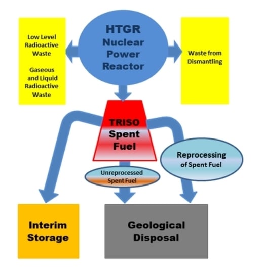
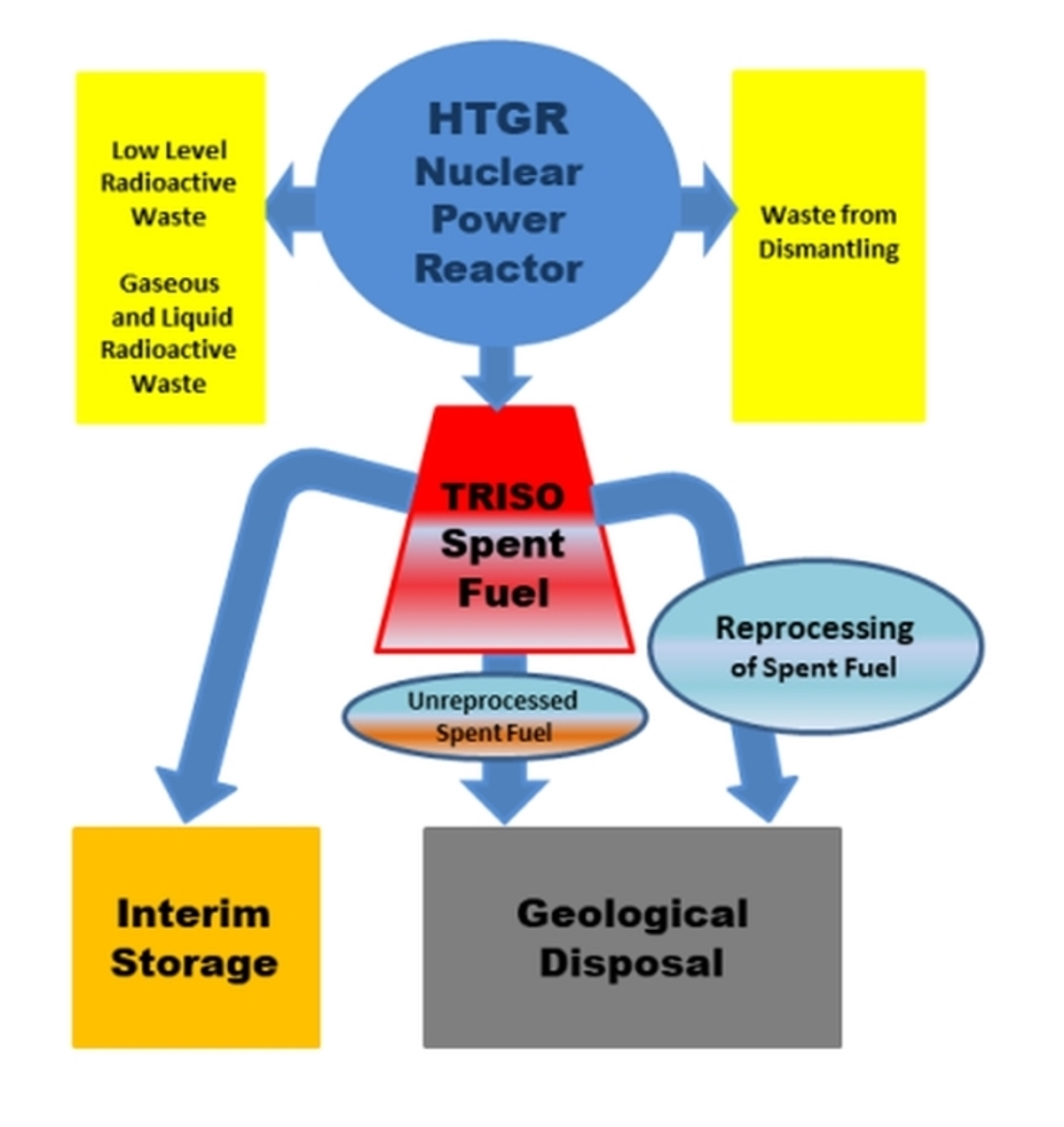
In terms of technology, two types of interim storage can be distinguished: wet or dry. The wet interim storage is usually the cooling pools next to the reactor. This type of solution is not often used at AFR locations. Both in AFR and in centralized storages, the most popular and expanding technology is the dry method. The specific techniques of the management of spent fuel from the reactor may differ by the implemented nuclear fuel cycle strategy. Two leading nuclear fuel cycle strategies—the once-through cycle (direct disposal or open cycle) and the twice-through cycle (recycling or partially closed cycle)—are showed in
Figure 2.
In the once-through cycle strategy, the fuel is used once and then is treated as a high-level waste (HLW) that has to be safely stored for millions of years until the level of its radiotoxicity obtains a natural uranium level or another optional safe reference level. In this strategy, the spent nuclear fuel is not treated by any chemical processes. There are only two steps considered: interim storage and final disposal. After the unloading spent nuclear fuel from reactor, it is stored in reactor pools for 5–10 years, then it is transported to the interim storage facility where is kept over 50–100 years. After this, it must be moved to deep geological disposal [
37]. The alternative option is putting the spent nuclear fuel through a sequence of chemical processes called reprocessing. In the first stage it is necessary to cool the spent nuclear fuel in a temporary storage facility and then transport it to the reprocessing plant. There, unused uranium and plutonium are recovered and then recycled as MOX nuclear fuel used in a dedicated nuclear reactor [
37]. The spent nuclear fuel contains also minor actinides (MA) and fission products (FP) that after separation are solidified in a glass matrix by vitrification and are then stored as HLW, intended for disposal in a deep geological repository. The advantages of the twice-through cycle is the recovering of more energy from recycled material used as nuclear fuel and the significant reduction in the volume of high-level waste to about one-fifth [
38]. The other advantage is that the level of radioactivity of the waste drops to just one-tenth of the initial value [
36]. It is important to reduce the volume of spent nuclear fuel stored because the accumulation of large amounts is a significant problem in the context of final disposal. The greatest part of spent nuclear fuel is put into the pool and stored there waiting for further solution or for a planned geological repository. Only small part (about 30%) of all of the spent nuclear fuel is processed at the present time [
39]. In the twice-through cycle, the spent nuclear fuel is considered to be a source of uranium and plutonium.
However, the final disposal of HLW or spent nuclear fuel (treated as HLW in the once-trough fuel cycle) is the last stage of fuel cycle, regardless of the adopted option. It is generally accepted that a deep geological repository (DGRs) is the only solution for the management of HLW for countries that do not have the spent nuclear fuel reprocessing technology. Currently, there is no operating DGR in the world, but a few are planned to be commissioned soon [
40].
It should be noted that the final stage of the back-end of the nuclear fuel cycle is the same in both schemes. At present, the most-considered option is deep geological disposal. The facility is planned to be placed underground in stable host rock that is can operate as a natural barrier for the isolation of radionuclides from the biosphere. Several countries have been studying deep geological repositories and, among them, Finland, Sweden, France and the United States are the most advanced. This option will allow for confining long-lived/high-level radioactive waste through putting it in stable rock deep under the ground and isolating it from humans and the environment above ground [
41]. The safeness of the disposal of radioactive waste in a geological repository is based on the natural barriers given by the repository host rock and its surrounds, and by the Engineered Barrier Systems (EBS). The different types of host rocks are being studied around the world. Some countries, among them, Canada, Finland, Spain, and Sweden, are considering hard rock formations, e.g., granite. The Netherlands, France, and Belgium are thinking about argillaceous formations (clay). In the Yucca Mountain, USA, there are studies regarding volcanic formations (tuff) [
36]. Moreover, two configurations of deep geological disposal are possible. The first one is the system of galleries, where waste is set alongside the axis. The second one is the structure of boreholes. These are drilled horizontal or vertical boreholes in the gallery. The waste is put in them. The aim of the EBS is to keep and/or retard the release of radionuclides from the waste into the repository environment. The EBS presents the simulated, engineered materials, comprised of various sub-systems or components—in particular, the waste container, buffer material, backfilling, seals, and plugs [
42]. The waste form is the first barrier. It includes the radioactive waste in the solid material called the matrix. The role of the waste matrix is to afford a firm waste form that is durable to leaching and to ensure a slow or even no release of radionuclides over a long period of time. The container is designed to make easier waste treatment, placement and recovery, and to ensure successful isolation for up to 1000 years or more, depending upon the character of the waste. The buffer/backfilling is to stabilize the thermohydro-mechanical-chemical conditions. Its second role is to afford low permeabilities and/or diffusivities, and/or prolonged delay. The role of seals, plugs, etc., is to avoid releases via shafts and underground tunnels and to avoid release to the repository [
43]. The differences in storage methods considered for HWL and ILW/LLW can be shown in the example of the Grimsel Test Site (GTS), located in the Swiss Alps. The high-level waste here is held in large steel disposal containers. These containers are placed on bentonite pedestals within the disposal tunnel that is then backfilled with bentonite [
44]. Whereas, LLW is placed within steel drums, and these steel drums are set into concrete disposal casks that are filled with mortar. Currently, most waste is stored in such a way that it is readily retrievable from storages.
One of the advantages of fourth generation reactors is the reduction of waste formation and emissions of greenhouse gases, while maintaining efficient energy production at the same time. Nonetheless, the safe treatment and storage of the spent TRISO fuel is one of the most important issues for developing HTGR reactors. It is necessary to treat these wastes properly, to transform them into forms that are acceptable for safe storage and disposal. The acceptable solutions to handle this kind of waste are not yet established, although it seems that this will be easier compared to the fuel from water reactors as a result of tightness of the TRISO covering layers and the confinement to avoid the release of radionuclides. In the 1980s, the following options for fuel storage from prismatic reactors were considered in the United States:
- -
whole blocks storage
- -
storage with prior removal of graphite
- -
reprocessing of the spent nuclear fuel to isolate of the fission products [
45,
46].
The direct storage of the nuclear fuel particles enclosed in the graphite medium of the fuel pebbles is related to a huge volume of waste requiring a big storage space. Forschungszentrum Jülich [
47,
48] was considering storing the fuel blocks in the ASSE salt mine in Germany.
A significant reduction in the volume of stored fuel could be achieved by separating the fuel from huge amounts of low-level radioactive graphite. The detached compacts or TRISO particles can be directed to the storage or can be reprocessed for U and Pu recovery. Guittonneau et al. [
49] proposed a method which allows the total degradation of graphite blocks and the separation of TRISO particles while maintaining their cohesion. The method was based on the intercalation of sulfuric acid into graphite layers to separate the grains. It was found that good partition of TRISO grains from the graphite matrix of compacts is preceded via acid treatment. It is necessary to note that this treatment allows for preventing damage to the spent TRISO fuel particles.
HTGR fuel is characterized by features that are important, not only during normal reactor operation and emergency situations, but also are useful in the conditions of temporary storage and final disposal of the spent nuclear fuel. Among them:
- -
the effective usage of uranium and plutonium generated in situ in low enriched fuel by high burn;
- -
isotopic composition of the spent nuclear fuel is not propitious to proliferate;
- -
the TRISO coatings which give a potential long resistant barrier to the transport of fission product and reduce the necessity for extra barriers;
- -
the low fuel power density, the using passive air cooling strategies cause that it is ready from the initial time to intermediate storage;
- -
the possibility to use disposal methods elaborated for medium active waste to spent HTGR fuel;
- -
consistent graphite matrix that reduces all spent nuclear fuel management efforts;
- -
resistant to corrosion in repository conditions (e.g., in salt decks), both matrix graphite and fuel particle coatings, allowing the use of a simple packaging concept for storage.
The existence of a series of barriers that prevent transport of radionuclides into the environment is a significant benefit in applying TRISO fuel in terms of its long-term safety. However, the stability of these layers and resistance to corrosive properties of the repository environment are important. Simulation tests and modelling studies allow the assessment of the long-term way of behaving of the fuel in this corrosive environment. They also enable evaluation of the rate of release of radionuclides into the environment in the conditions of damage to subsequent protective repository barriers.
The modelling and analysing of decomposition rates of the spent fuel from HTGR have been done by Peterson and Dunzik-Gougar [
50] in relation to planned permanent geological disposal. Their aim was to find the parameters that would have the most impact on broad behaviour of the fuel. The following fuel particle parameters were analysed: kernel composition, outer pyrolytic carbon layer thickness, thickness of SiC layer, buffer layer and thickness of inner coat layer, SiC layer strength, temperature effect on the variability of the breakdown rate of TRISO fuel and the rapidity of SiC and outer dense pyrolytic carbon layers corrosion. The modelling was performed without taking into consideration engineering barriers of geological disposal. The SiC layer can be compared to a pressure container which maintains gases formed through nuclear fission. Based on the above assumption, TRISO fuel was designed as a pressure vessel that lets down when the stress in the layer of the SiC surpasses the layer strength. The study showed that in the repository environment the estimated time needed for particle failure is strongly dependent on the rate of corrosion, temperature change over time, and the thicknesses of the outer pyrolytic carbon and SiC layers. However, parameters, like the kernel dimensions, carbon buffer layer, inner coat of dense pyrolytic carbon layer, the strength of silicon carbide layer and the pressure inside TRISO particle, did not importantly influence on the time needed for particle failure. The comprehension of matters of the corrosion rates of the outer pyrolytic carbon and SiC layers and improving the quality control of the outer pyrolytic carbon and SiC layers thickness are very important. This could help remarkably in terms of reducing uncertainty in the assessed failure time of the spent TRISO fuel in a repository environment.
The vitrification of TRISO particles before placing them into a future geological repository [
51,
52] is also considered. Glass is another barrier that protects fuel particles against corrosion caused by groundwater and radionuclides spreading in the environment.
Preliminary studies showed that it is possible to immobilize TRISO-fuel particles in a borosilicate glass matrix. This type of matrix is being used for LLW and HLW vitrification, e.g., in France [
51]. Two methods of vitrification are taken into account: vitrification by melting and vitrification by sintering. The confinement of TRISO-fuel in sintered glass seems to be preferable compared to the melted glass method. The following advantages of sintered glass were identified:
- -
the process proceeds at low temperature in the air atmosphere. In these conditions the TRISO-particles better retain their physical properties. No fractures in particles were observed;
- -
it is characterized by features allowing coating the TRISO-particle without macroscopic bubbles;
- -
the thermal processing of TRISO particles prior to vitrification is not necessary;
- -
good chemical strength of obtained sintered glass-TRISO-particles composite.
The alternative method, vitrification by melting, demands high treatment temperatures (approximately 1150 °C) and has to proceed in an atmosphere of inert gas. This is important because oxidation of the TRISO-coatings may cause the releasing of volatile radionuclides, among them C-14, I-129, Cs-134, Cs-135, and Cs-137. It should be anticipated that caesium radionuclides may be well immobilized in the glass, however it seems far more complicated for C-14 and I-129. Most countries prefer the borosilicate glass for vitrification of HLW. However, for example, in Russia there are also attempts to use an aluminium-phosphate matrix [
53].
Large quantities of irradiated graphite production are a serious problem in HTGR reactors. There are about 250,000 t of irradiated carbon worldwide. The basic strategy for reactor graphite is to disassemble reactor cores after a period of immobility (typically 85 years) and transfer graphite to a storage or disposal site [
26,
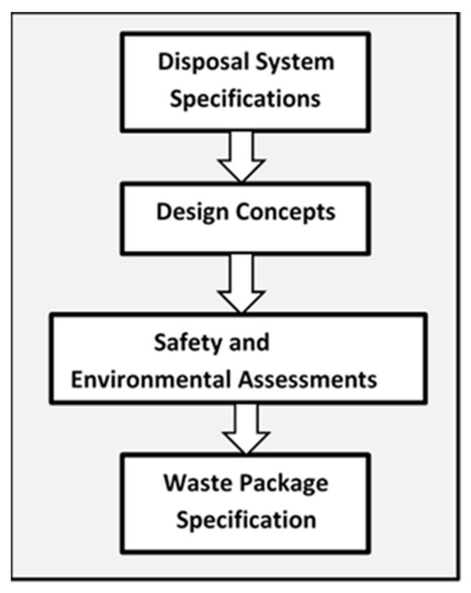
54]. The waste packages for HLW require some specific characteristics that allow for storing them safely for a long time. A Generic Waste Package Specification published in 2012 [
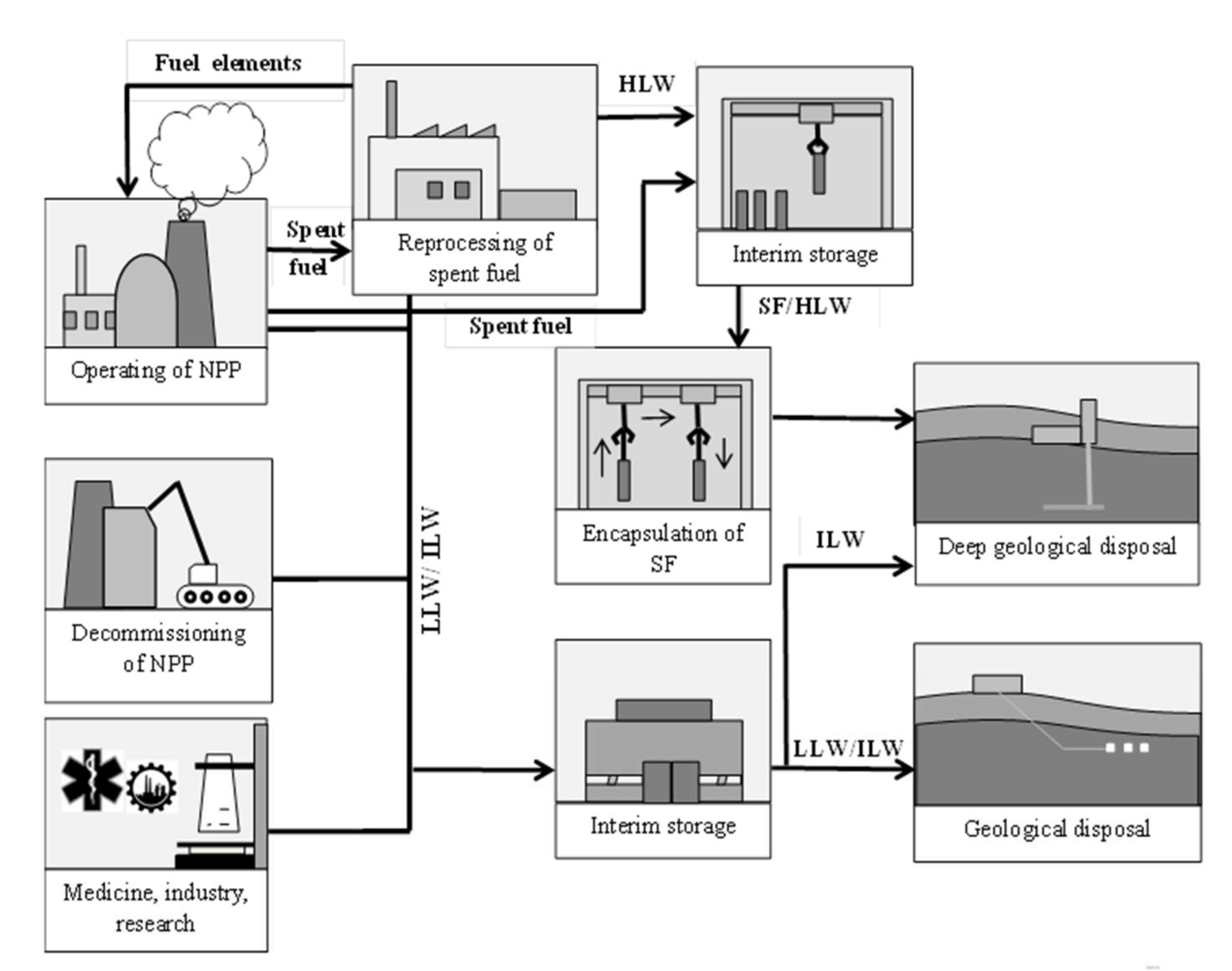
55] represents a high-profile document in a hierarchy of packaging specifications related to geological disposal in general and the packaging of waste in particular. In the geological disposal concept, the information about safety and environmental assessments and about waste package specification, as it was presented in
Figure 3, should be also included.
The choice of irradiated graphite processing methods should be established on examination of economic, environmental friendly and sustainable ways. Three main aims should be considered in terms of irradiated graphite treatment processes:
- -
the radionuclides removing from graphite and change radioactive classification of graphite (which means to convert ILW into LLW). Moreover, the removal of long-lived radionuclides could make the graphite acceptable for placement in the near-surface repository;
- -
conversion of the irradiated graphite to an inactive matrix;
- -
the significantly reduction of the volume of waste.
The main processing methods of irradiated graphite include Wigner energy elimination, thermal processing, chemical processing, immobilization and gasification [
56]. Then, there are the following possible options for handling irradiated graphite: gasification with release of gaseous products to the environment, and storage in a near-surface or at-surface facility or a deep geological repository.
5. TRISO Spent Fuel Reprocessing Options
There are three primary possibilities for the management of the spent TRISO nuclear fuel considered: (1) reprocessing, (2) disposal in a geological repository or (3) long-term on-site storage. The best solution would be to transport the spent TRISO nuclear fuel offsite shortly after unloading from the nuclear HTGR reactor to the reprocessing facility or to a geological repository for the final disposal. Nonetheless, the availability of these solutions varies by country or region. If transport offsite is not an accessible possibility, the spent TRISO nuclear fuel will therefore need to be kept on-site up to a time when such a possibility will be available [
57].
For recycling HTGR spent nuclear fuel several strategies can be considered, such as: without recycling, mixed methods of recycling, one time through recycling, or complete recycling [
17].
Among the first steps in the reprocessing of spent nuclear fuel of the HTGR is the separation of high-activity fuel from the graphite. This is an important and challenging step because of the significantly hard coat of the TRISO fuel particle [
57]. A few countries have tried to develop useful methods for the breaking of TRISO particles and reprocessing in order to recover uranium or thorium, e.g., the ORNL (Oak Ridge National Laboratory) in the USA, FZJ (Forschungszentrum Jülich) GmbH in Germany, CEA (Commissariat a l’Énergie Atomique) in France and JAEA (Japan Atomic Energy Agency) in Japan. At the ORNL in the 1960s and 1970s, and at FZJ in the 1980s, at the laboratory scale and, after that, at the pilot plant scale, the processing of the HTGR spent fuel was studied. The first step of the research was the recovery of oxide kernels containing uranium and thorium by removing the carbon and silicon carbide coats. Then, uranium and thorium were recycled from fission products using the THOREX method. In the first step, the oxides were dissolved in the mixture of nitric acid and hydrofluoric acid and then thorium and uranium were recovered by the solvent extraction process using TBP in the organic phase [
58,
59]. At the ORNL laboratories, the different kinds of jaws and hammer crushers, ball mills, pneumatic and cyclone separators, etc., were examined for block-type compacts and pebble TRISO spent fuel. The complete fragmentation of the TRISO particle layers was not possible, even using a modern method of a high-speed impaction grinding. At FZJ (Germany) laboratories, in the 1980s, a demonstration test was done and around 11,000 fresh pebbles of TRISO particles were treated by grinding and combustion [
59]. At the ORNL and FZJ laboratories, the joint methods for the processing of the spent TRISO fuel, such as grinding, and combustion, followed by THOREX process, were performed, with obtained recovery yields of U and Th ~95%. Bearing in mind the radiotoxicity of the waste in its final form, and the limitation of the off-gas released activity, there is a need for greater recovery yields. At the CEO laboratories in Marcoule, the additional improvements for the reprocessing of the spent TRISO fuel were applied. The mechanical extraction of the HTGR compacts from the spent TRISO fuel blocks seems to be a favourable method, as well as eliminating graphite from the compacts by means of pulsed currents and by oxidizing thermal methods to free the particles, and to reach the fissile compound [
60]. For the fabrication process of the kernels the method of gelation seems to be appropriate, especially for the efficient recycling of actinides [
60,
61].
A brand new approach for the reprocessing of spent TRISO fuel was proposed by Liyang Zhu et al. [
62,
63]. The extraction efficiency of the UO
2 powder obtained after grinding the UO
2 pellets from HTGR spent fuel using TBP-nitric acid mixture in supercritical CO
2 is almost 92%, and the U
3O
8 extraction yield is 98%. U
3O
8 fine powder was obtained after UO
2 pellets were broken spontaneously into U
3O
8 at a temperature of 600 °C in an O
2 stream and with the TBP-nitric acid system in supercritical CO
2 [
62]. The spent TRISO fuel particles were recovered from graphite components by electrochemical intercalation, obtaining a mix of U
3O
8 powder and SiC shells. Uranium oxide (U
3O
8) powder was transformed into solid uranyl nitrate by conversion using liquid N
2O
4, and then uranyl nitrate was recycled by supercritical CO
2 containing TBP as complexing agent, with the residue of silicon carbide shells. The efficiency of the selective extraction of uranium was ~98% (at 50 °C and 25 MPa), while there was no extraction of silicon carbide by TBP [
63].
Another study of disintegration the graphite matrix has been carried out, using the electrochemical method with a salt of ammonium nitrate as a suitable electrolyte. The obtained results prove that the developed electrochemical method with salt like the electrolyte is a good route to disintegrate the graphite medium from the HTGR spent fuel components [
64]. The complete removal of different layers from coated TRISO particles is difficult and the combined methods of dry and wet oxidation at 800–1000 °C can be applied for reprocessing and the selective recovery of uranium from UO
2 microspheres prepared by the internal gelation procedure [
65].


