
Composite Non-Linear Control of Hybrid Energy-Storage System in Electric Vehicle


Hunan Institute of Engineering, College of Computer and Communication, Xiangtan 411104, China
*
Author to whom correspondence should be addressed.
Energies 2022, 15(4), 1567; https://0-doi-org.brum.beds.ac.uk/10.3390/en15041567
Submission received: 27 January 2022
/
Revised: 15 February 2022
/
Accepted: 18 February 2022
/
Published: 21 February 2022
(This article belongs to the Topic Power System Modeling and Control)
Abstract
:The underlying circuit control is a key problem of the hybrid energy-storage system (HESS) in electric vehicles (EV). In this paper, a composite non-linear control strategy (CNC) is proposed for the accurate tracking current/voltage of the fully-active HESS by combining the exact feedback linearization method and the sliding mode variable structure control technology. Firstly, by analyzing the circuit characteristics of HESS, the affine non-linear model of fully-active HESS is derived. Then, a rule-based energy management strategy (EMS) is designed to generate the reference current value. Finally, the HESS is linearized by the exact feedback linearization method, and the proposed CNC strategy is developed combined with sliding mode variable structure control technology to ensure fast response, high performance, and robustness. At the same time, the stability proof based on the Lyapunov method is given. Moreover, the performance of the CNC strategy is thoroughly investigated and compared with simulation studies with the traditional PI control and a modified sliding mode control, and its effectiveness under different driving conditions is fully verified.
1. Introduction
With the rapid growth of global vehicle ownership, energy shortages and environmental pollution have become increasingly serious, which has a serious negative impact on the sustainable and healthy development of the vehicle industry. As one of the ideal models of new energy vehicles, electric vehicles (EV) have attracted extensive attention and attention because of their zero-emission and low-pollution characteristics. Nevertheless, the battery energy-storage system of an EV has the disadvantages of low power density and short cycle life, which will lead to insufficient power during vehicle driving and increase the maintenance cost of vehicle energy sources [1]. As a new energy-storage element, the supercapacitor has a high power density and long cycle life compared with the battery. It can meet the peak power demand of vehicle driving well, avoid high current discharge of the battery, and make use of its fast charging and discharging speed to efficiently recover vehicle regenerative braking energy and improve energy utilization. The HESS consisting of the battery, the supercapacitor, and the DC/DC converter can meet the driving needs of vehicles well. It is an important development direction of EV energy sources in the future [2].
At present, the research on HESS can be divided into two categories: one is to design top-level EMS to distribute the required power to each energy-storage element reasonably and efficiently to generate reference, such as rule-based [3], fuzzy control [4], dynamic programming [5], and neural networks [6], etc. The other is to design the underlying control strategy by considering the interaction between different components so that the EMS can be implemented as expected. Previously, most researchers were committed to designing EMS to obtain high economy. However, due to the combination of multiple components, the HESS has multi-variable, non-linear, and strong coupling characteristics. How to realize the underlying control under the condition of multi-component coupling and strong non-linearity and ensure the safe and stable operation is also a key technical problem of the HESS. In [7], an advanced topology was proposed for the HESS, which can achieve a smooth transition and maintain stability when the load fluctuates. Nevertheless, its practicability and effectiveness need to be further verified. In [8], a fractional-order proportional-integral-derivative (PID) controller was proposed for the coordinated control of the fuel cell and the supercapacitor in hybrid renewable energy systems. Nevertheless, as a linear controller, PID is very sensitive to parameter changes and is not suitable for the control method of complex non-linear systems. In [9], combined with the port-controlled Hamiltonian (PCH) model and L2 gain control method, an L2 gain adaptive robust control (L2-ARC) strategy was developed to stabilize the output of the HESS. Nevertheless, the control process is more complicated.
Recently, the exact feedback linearization method and the sliding mode variable structure control technology have been widely studied. As a non-linear control method, exact feedback linearization can globally linearize the non-linear system through coordinate transformation and input/output linearization, to further analyze and control [10]. An exact feedback linearization control strategy for voltage source converters (VSCs) in smart distribution systems and microgrids was proposed, which was studied by using the equivalent linear model with non-linear characteristics, and the effective control effect was obtained [11]. Nevertheless, the effectiveness of exact feedback linearization depends on the accurate description of the system’s non-linearity, which is highly dependent on the accuracy of the mathematical model. As a non-linear robust control, sliding mode variable structure control (SMC) technology has been widely applied with satisfactory control performance, such as a robotic system [12], vehicle control [13], DC motor [14], power electronics [15], and power system [16], etc. Based on the fifth-order averaged model, the classical sliding mode current controller and the Lyapunov-based voltage controller were designed to realize the underlying circuit control for the fully-active HESS [17]. For the HESS composed of the fuel cell/battery/supercapacitor, a terminal sliding mode control strategy with adaptive law was presented to realize the stable tracking of the current and maintain voltage stability [18]. A simple multimode HESS was designed for EVs, and an adaptive sliding mode control strategy with hysteresis control was presented combined with the practical application, which effectively improves the system efficiency and ensures the safety of the battery [19]. Nevertheless, the inherent chattering of sliding mode control will harm the control effect.
In this paper, the exact feedback linearization method and the sliding mode variable structure control technology were combined, and a composite non-linear control strategy was proposed for the underlying circuit control of the fully-active HESS. After exact feedback linearization, the HESS establishes the linear switching function, which is helpful to improve the dynamic quality of the sliding mode variable structure. The sliding mode variable structure is insensitive to system uncertainty and disturbance, which eliminates the strong dependence of the exact feedback linearization method on the accuracy of the mathematical model. The main contributions of this work are as follows:
- (1)
- Through the exact feedback linearization and non-linear coordinate transformation, the original non-linear system is transformed into a linear system, which is convenient for controller design;
- (2)
- The exponential reaching law and integral sliding mode surface are combined to improve the convergence speed of the system and effectively weaken the chattering of sliding mode variable structure;
- (3)
- The control performance under different conditions was tested and compared with the traditional PI control and a modified sliding mode control. The results show that the proposed CNC strategy has faster corresponding speed, smaller overshoot, and better steady-state chattering, which proves the effectiveness of the proposed CNC strategy.
2. The Model of Fully-Active Hybrid Energy-Storage System (HESS)
2.1. The Circuit Model
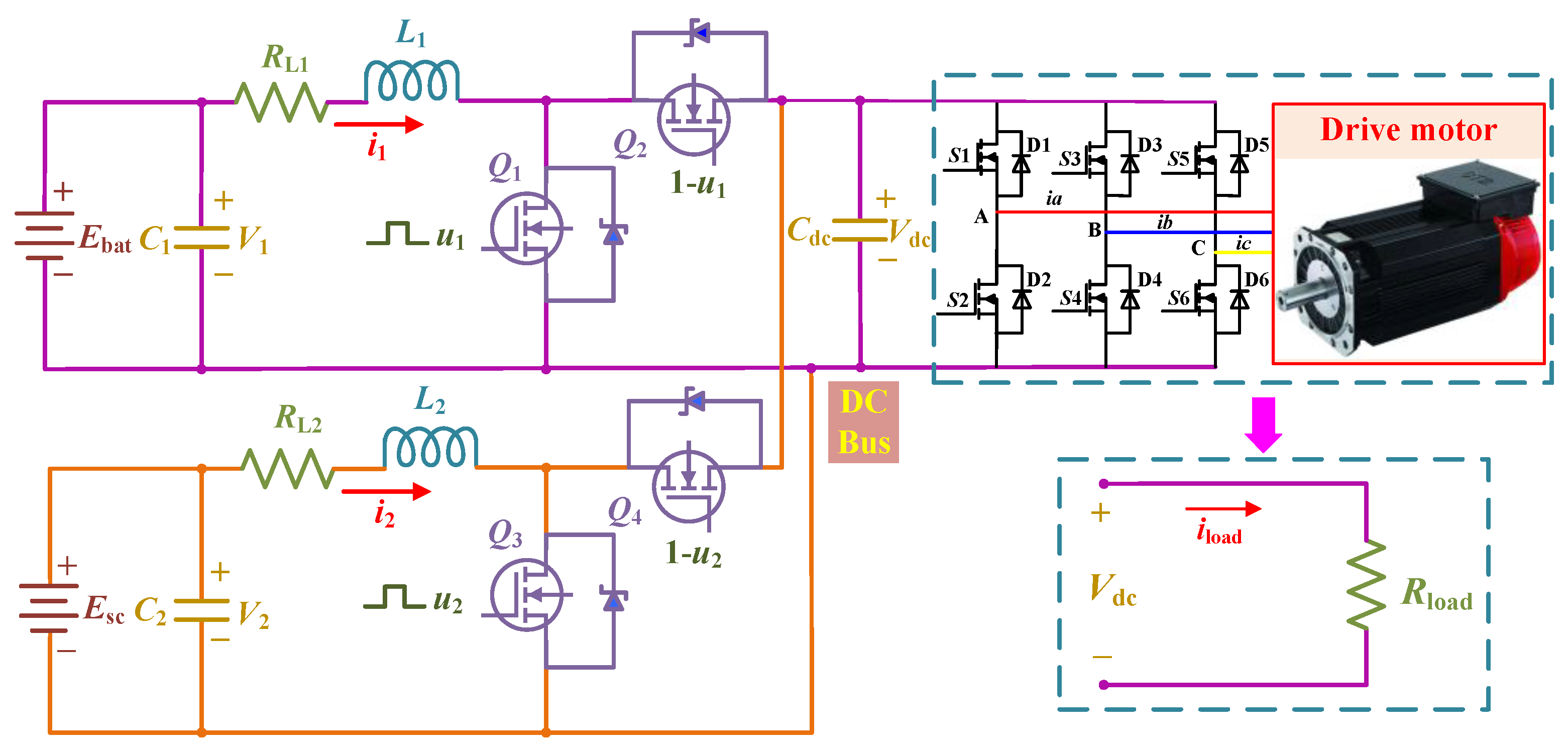
Currently, there are three types of HESS topologies: passive, semi-active and fully active. Considering the control effect, the fully-active HESS is selected as the research object, with its circuit model shown in Figure 1. It consists of a battery pack, a supercapacitor pack, two standard bidirectional DC/DC converters, a DC/AC inverter, and a driving motor. The standard bidirectional DC/DC converter consists of two Insulated Gate Bipolar Transistors (IGBTs), an inductor, and a common capacitor. The switches Q1, Q2, Q3, and Q4 adopt complementary PWM control method. When Q1 is on (off), Q2 is off (on), Q3 and Q4 are the same. Compared with the independent control, the complementary control does not need the transition switching of buck and boost circuit, which improves the work efficiency and system response speed. To simplify the research process, a load resistance with variable current iload is used to substitute for the driving system composed of DC/AC inverter and driving motor, and the influence of series resistance of the battery and the supercapacitor is ignored. Based on Kirchhoff’s law, the state Equations of the HESS circuit model are as follows:
where L1 and L2 are the inductors of the battery side and the supercapacitor side, i1 and i2 are the currents flowing through them, and RL1 and RL2 are the series resistances of L1 and L2; C1 and C2 are the filter capacitors of the battery side and the supercapacitor side, Cdc is the DC bus capacitor, V1, V2, and Vdc are the voltages corresponding to capacitors C1, C2, and Cdc; u1 and u2 are the duty cycle of switch Q1 and Q3; Ron1, Ron2, Ron3, and Ron4 are the on-resistances of the complementary switches Q1, Q2, Q3, and Q4, respectively. In this study, it can be assumed that they are equal, then the above state equations can be simplified as:
2.2. The Affine Non-Linear Model
For the multi-input and multi-output (MIMO) affine non-linear systems, the system model is as follows [20]:
where x is the n × 1 order state vector, u is the m×1 order control variable, y is the m × 1 order output vector, f(x) is the smooth vector field, g(x) is the n × m order matrix.
The main control objective of the HESS is that the current of the battery and the supercapacitor can accurately track the reference value, and the bus voltage can be stable at the target voltage. Therefore, to realize the current tracking control, it can be assumed that the bus voltage is stable. According to Equations (4)–(6), selecting x = [x1 x2]T = [i1 i2]Tas state variables, y = [y1 y2]T = [h1(x) h2(x)]T = [i1 i2]T as output variables, u = [u1 u2]T as control input variables, the affine non-linear model of the HESS can be obtained as follows:
where
3. The Composite Non-Linear Strategy
This part gives the design scheme of the CNC strategy. Firstly, a rule-based EMS is introduced to generate reference values; secondly, the exact linearization conditions of the HESS are derived; then, the linearized control model of the HESS is obtained by non-linear coordinate transformation; finally, combined with exponential reaching law and integral sliding mode surface, the voltage/current tracking controller is designed, and the stability proof based on Lyapunov theory is given.
3.1. The Rule-Based Energy Management Strategy (EMS)
Before the control strategy design, an energy management strategy (EMS) needs to be designed to distribute the required power, to obtain the power between the battery and the supercapacitor, while generating the current reference value of the battery.
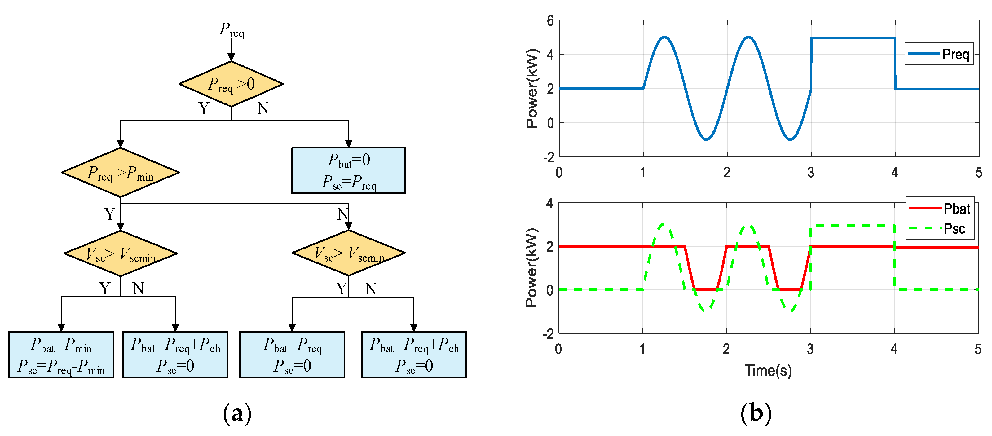
A rule-based EMS is used to manage the energy of HESS in this paper. The specific design is shown in Figure 2a, where Preq is the required power of the load, Pbat is the power of the battery, Psc is the power of the supercapacitor, Pch is the charging power of the supercapacitor, Pmin is the threshold power, Vsc is the voltage of the supercapacitor, Vscmin is 60% of the rated voltage of the supercapacitor. When Preq < 0, the vehicle is in braking mode, and the supercapacitor is used to receive the power of the load. When Preq > 0, the vehicle is in driving mode, which can be divided into two situations:
- (a)
- When Preq > Pmin: if Vsc > Vscmin, the battery bears the threshold power Pmin, and the supercapacitor bears the remained power; if Vsc < Vscmin, the battery bears the required power Preq and to charge the supercapacitor with the charging power Pch.
- (b)
- When Preq < Pmin: if Vsc > Vscmin, the battery bears the required power Preq; if Vsc < Vscmin, the battery bears the required power Preq and to charge the supercapacitor with the charging power Pch.
Figure 2b shows the artificial load power and the distributed results of the battery and the supercapacitor. It can be seen that the output power of the supercapacitor fluctuates greatly, while the output power of the battery is smooth, which shows the EMS is helpful to protect the battery.
3.2. The Exact Linearization Conditions
The exact linearization conditions of the affine non-linear model are given below [21]. If the following two conditions are true for the affine non-linear model shown in Equation (8):
- (1)
- For all x0 near x, the rank of matrix [g1(x) g2(x) adfg1(x) adfg2(x)] is constant and equal to n.
- (2)
- The vector field set D = {g1(x) g2(x) adfg1(x) adfg2(x)} is involutive at x = x0.
Then, there must be output functions [h1(x) h2(x)]T such that the correlation degree r of the system at x = x0 is equal to the order n of the system. When the output function satisfies the total relation degree r = n, the linear system expression can be obtained by coordinate transformation directly to realize decoupling. If the output function does not satisfy the total relation degree r = n, it is needed to find another output function ω(x) to meet the condition, and then coordinate transformation is carried out.
Firstly, the exact linearization conditions of the system are verified:
It can be seen that the rank of matrix [g1(x) g2(x) adfg1(x) adfg2(x)] is 2, which is equal to the system order n. Therefore, condition (1) is satisfied. Obviously, for condition (2), when the system order n = 2, the vector field set D is involution. It can be concluded that there must be a set of output functions such that the correlation degree r of the system is equal to the order n of the system.
Next, verify whether the selected output function [h1(x) h2(x)]T satisfies r = n. The correlation degree of the system can be calculated by the Lie derivative:
It can be seen from Equations (11) and (12) that under the given output, the total correlation degree r = r1 + r2 = 1 + 1 = 2 = n, where r1 and r2 are the correlation degree of output functions h1(x) and h2(x), respectively. The system is non-linear for the state variable x but linear for the control output variable u. Therefore, the non-linear coordinate transformation can be carried out directly to realize the linearization of the non-linear system.
3.3. Non-Linear Coordinate Transformation
For MIMO (multiple-input multiple-output) systems, one of the input-output feedback linearization methods is to derive the output y of the system until the control input variable u appears. Therefore, the derivation of [y1 y2]T can be obtained as follows:
where,
Due to E(x) being a non-singular matrix, it can obtain the following results by matrix transformation:
3.4. The Voltage/Current Tracking Controller
For the HESS, the control objective is that the current i1 and the current i2 track the reference value accurately. However, the feedback linearization requires the high accuracy of the system model. In order to enhance the robustness of the system, sliding mode variable structure control is introduced into the original decoupling system. The HESS after coordinate transformation is a controllable linear system, so the linear switching function can be selected. Let its reference current value be yref = [y1ref y2ref]T = [i1ref i2ref]T, the current tracking error is defined as follows:
In order to eliminate the influence of chattering on the controller, the integral sliding surface is selected as follows:
The derivation of Equation (16) shows that:
The exponential reaching law is selected to design [22]:
where k is the sliding mode gain, ε is the exponential reaching rate. In order to reduce the chattering of the system, the continuous function θ(s) is used instead of the symbolic function sgn(s):
where δ is a small positive number. Combined with Equations (17)–(19), the following Equation can be obtained:
The PWM duty ratio can be solved such that:
The current reference value of battery i1ref in Equation (15) is obtained by the energy management strategy:
The circuit loss is ignored. The current reference value of supercapacitor i2ref in Equation (15) can be obtained from the power conservation theorem:
To ensure that the DC bus voltage can be stable at the target voltage, the sliding surface is defined as follows:
where Vdcref is the target DC bus voltage. When the system is stable, the DC bus voltage will be stable at the target value, and the tracking error is zero.
Combining the exponential reaching law described in Equations (18) and (19), the sliding mode control law of bus voltage can be obtained:
By adding the voltage stability term u(t) to Equation (23), the bus voltage can be controlled to stabilize at the target value. Equation (23) can be rewritten as:
To ensure the stability of the control system, the Lyapunov function is defined as follows:
The differential of Equation (27) can be obtained as follows:
Due to ki > 0, εi > 0, i = 1,2, and δ is a small positive number. It can be obtained as follows:
Therefore, according to the Lyapunov theory, the stability of the designed control strategy is proved. Figure 3 presents the overall diagram of the proposed EFL-SMC strategy.
4. Simulation and Analysis
In order to evaluate the control performance of the proposed CNC strategy, the simulation model was established in Simulink and compared with the traditional proportional−integral (PI) control and a modified sliding mode control (E-GSMC) [23]. The simulation includes: dynamic response performance (see 4.1), robust tracking performance (see 4.2), and a typical driving cycles test (see 4.3). The selected component parameters of the simulation model are listed in Table 1. In particular, the nominal voltage of the battery pack is 180 V and the initial SOC is set as 90%; the nominal voltage of the supercapacitor pack is 150 V; the target DC bus voltage is 200 V; the frequency of pulse width module is 10 kHz; the Pmin and Pch in the energy management strategy are set to 3000 W and 200 W, respectively. Because of the small fluctuation of bus voltage in the control process, the parameters in the controller are set as follows: c11 = 1, c12 = 2, c21 = 1, c22 = 2, k1L1/Vdc = 10, ε1L1/Vdc = 3, k2L2/Vdc = 20, ε2L2/Vdc = 2, k3 = 2, ε3 = 0.2, δ = 0.001.
4.1. The Simulation Results of the Dynamic Response Performance
To investigate the dynamic response characteristics, the load required power Preq was set as 0 W→6000 W at times 0 s and 0.05 s. Figure 4, Figure 5 and Figure 6 show the dynamic response curves of the battery current, the supercapacitor current, and the bus voltage under three control strategies (PI, E-GSMC, CNC). It can be seen that the three control strategies have a certain overshoot in the starting process, and the proposed CNC strategy has a shorter steady-state time and less error chattering in the initial stage. When the reference value changes suddenly, it has a faster response speed and smaller overshoot than the PI control strategy and the E-GSMC strategy.
4.2. The Simulation Results of the Robust Tracking Performance
To investigate the robust tracking performance, the load required power Preq was set as 4000 W→7000 W→−2000 W→5000 W→2000 W at times 0 s, 1s, 2 s, 3 s, and 4 s. As shown in Figure 7, there is little difference in the robust tracking performance of battery current under the three control strategies, and the tracking error of the proposed CNC strategy is slightly improved compared with the PI control strategy and the E-GSMC strategy. As shown in Figure 8, the robust tracking performance of supercapacitor current under the three control strategies shows little difference in steady-state tracking, but when the reference current changes, the fluctuation of the PI control strategy is the largest, followed by the E-GSMC strategy, and the proposed CNC strategy is the smallest. As shown in Figure 9, the bus voltage under the three control strategies can be stable at the target voltage, but when the load required power changes, both PI control strategy and E-GSMC strategy fluctuate greatly, while the fluctuation of the proposed EFL-SMC strategy is the smallest, its overshoot decreases significantly, and its steady-state chattering is significantly less than that of the PI control strategy and E-GSMC strategy. The three strategies were simulated three times and the time costs were recorded. As shown in Table 2, it can be seen that the time for PI control is shorter because the control process is relatively simple. Compared with the E-GSMC strategy, the time cost of CNC is significantly smaller. These confirm that the proposed CNC strategy has a better robust tracking performance.
4.3. The Simulation Results of the Typical Driving Cycles Test
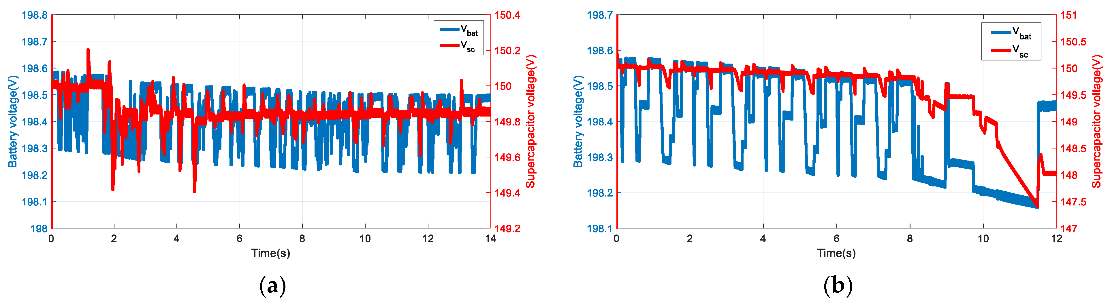
To investigate the effectiveness of the proposed EFL-SMC strategy, the test was conducted under two typical driving cycles––the Urban Dynameter Driving Schedule (UDDS) and the New European Driving Cycle (NEDC). Figure 10 presents the load required power of the UDDS/NEDC driving cycle and the power split results between the battery and supercapacitor with the rule-based EMS. Here, the load required power was optimally distributed to the battery/supercapacitor. The battery only needs to bear the threshold power, and the peak power was borne by the supercapacitor, which effectively protects the battery. Figure 11, Figure 12 and Figure 13 present the tracking curves of the battery current, the supercapacitor current, and the bus voltage under the UDDS/NEDC driving cycle. It can be seen that both battery current and supercapacitor current can accurately track the target value under two typical driving cycles. The bus voltage can also be stable at the target value with the maximum error less than 3.5 V under the UDDS driving cycle and less than 6.5 V under the NEDC driving cycle. Figure 14 presents the voltages curves of the battery and supercapacitor under the UDDS/NEDC driving cycle. It can be seen that the voltage of the battery is relatively smooth, while the voltage of the supercapacitor fluctuates greatly. These confirm the effectiveness of the proposed CNC strategy under different driving conditions.
5. Conclusions
This paper presents a composite non-linear control strategy (CNC) by combining the exact feedback linearization method and the sliding mode variable structure control technology for the control of the fully-active HESS. Firstly, the affine non-linear model of fully-active HESS was established by deriving the circuit model. Then, a rule-based EMS was designed to distribute the required power. Finally, by combining the exact feedback linearization method with the sliding mode control technology, the CNC strategy was developed to ensure high performance and robustness of the control. According to the simulation results, the effectiveness of the proposed CNC strategy could be confirmed. The developed CNC strategy could reasonably distribute the required power between the battery and the supercapacitor, and realize the robust tracking of the battery/supercapacitor current reference value with maintaining the bus voltage stability. This provides a new idea for the control of the HESS.
Author Contributions
Conceptualization, Z.L. and X.Z.; methodology, Z.L. and X.Z; software, Z.L.; validation, Z.L. and X.Z.; formal analysis, X.Z.; investigation, Z.L.; resources, X.Z.; data curation, Z.L.; writing—original draft preparation, Z.L.; writing—review and editing, X.Z.; visualization, Z.L.; supervision, X.Z.; project administration, X.Z. All authors have read and agreed to the published version of the manuscript.
Funding
This work was supported by the National Natural Science Foundation of China (62173134), the Natural Science Foundation of Hunan Province (2020JJ6024), the Scientific Research Fund of Hunan Provincial Education Department (19K025, 21B0652), and the Scientific Research Project of Hunan Institute of Engineering (21016).
Data Availability Statement
Not applicable.
Acknowledgments
Authors would like to thank the editor and anonymous reviewers for their patient and valuable comments on this paper.
Conflicts of Interest
The authors declare no conflict of interest.
References
- Raman, S.R.; Cheng, K.; Xue, X.D.; Fong, Y.C.; Cheung, S. Hybrid Energy Storage System with Vehicle Body Integrated Super-Capacitor and Li-Ion Battery: Model, Design and Implementation, for Distributed Energy Storage. Energies 2021, 14, 6553. [Google Scholar] [CrossRef]
- Nguyen, H.; Nguyn, B.H.; Vo-Duy, T.; Trovo, J. A Comparative Study of Adaptive Filtering Strategies for Hybrid Energy Storage Systems in Electric Vehicles. Energies 2021, 14, 3373. [Google Scholar] [CrossRef]
- Peng, J.; He, H.; Xiong, R. Rule based energy management strategy for a series-parallel plug-in hybrid electric bus optimized by dynamic programming. Appl. Energ. 2017, 185, 1633–1643. [Google Scholar] [CrossRef]
- Zhang, X.; Lu, Z.; Tan, C.; Wang., Z. Fuzzy Adaptive Filtering-Based Energy Management for Hybrid Energy Storage System. Comput. Syst. Sci. Eng. 2021, 36, 117–130. [Google Scholar] [CrossRef]
- Song, Z.; Hofmann, H.; Li, J.; Han, X.; Ouyang, M. Optimization for a hybrid energy storage system in electric vehicles using dynamic programing approach. Appl. Energ. 2015, 139, 151–162. [Google Scholar] [CrossRef]
- Zhu, T.; Wills, R.; Lot, R.; Ruan, H.; Jiang, Z. Adaptive energy management of a battery-supercapacitor energy storage system for electric vehicles based on flexible perception and neural network fitting. Appl. Energ. 2021, 292, 116932. [Google Scholar] [CrossRef]
- Jung, H.; Wang, H.; Hu, T. Control design for robust tracking and smooth transition in power systems with battery/supercapacitor hybrid energy storage devices. J. Power Sources 2014, 267, 566–575. [Google Scholar] [CrossRef]
- Nosrati, K.; Mansouri, H.R.; Saboori, H. Fractional-order PID controller design of frequency deviation in a hybrid renewable energy generation and storage system. Cired Open Access Proc. J. 2017, 1148–1152. [Google Scholar] [CrossRef] [Green Version]
- Zhang, X.; Lu, Z.; Yuan, X.; Wang, Y.; Shen, X. L2-Gain Adaptive Robust Control for Hybrid Energy Storage System in Electric Vehicles. IEEE Trans. Power Electr. 2021, 36, 7319–7332. [Google Scholar] [CrossRef]
- Oliveira, L.; Bento, A.; Leite, V.; Gomide, F. Evolving granular feedback linearization: Design, analysis, and applications. Appl. Soft Comput. 2019, 86, 105927. [Google Scholar] [CrossRef]
- Montoya, O.D.; Garcés, A.; Serra, F.M. DERs integration in microgrids using VSCs via proportional feedback linearization control: Supercapacitors and distributed generators. J. Energy Storage 2018, 16, 250–258. [Google Scholar] [CrossRef]
- He, S.; Xu, Y.; Wu, Y.; Li, Y.; Zhong, W. Adaptive Consensus Tracking of Multi-Robotic Systems via Using Integral Sliding Mode Control. Neurocomputing 2021, 455, 54–162. [Google Scholar] [CrossRef]
- Wang, J.; Luo, X.; Wang, L.; Zuo, Z.; Guan, X. Integral Sliding Mode Control Using a Disturbance Observer for Vehicle Platoons. IEEE Trans. Ind. Electron. 2020, 67, 6639–6648. [Google Scholar] [CrossRef]
- Wang, Y.; Zhang, X.; Yuan, X.; Liu, G. Position-Sensorless Hybrid Sliding-Mode Control of Electric Vehicles with Brushless DC Motor. IEEE Trans. Veh. Technol. 2011, 60, 421–432. [Google Scholar] [CrossRef]
- Gong, C.; Sou, W.L.; Lam, C.S. Second-Order Sliding-Mode Current Controller for LC-Coupling Hybrid Active Power Filter. IEEE Trans. Ind. Electron. 2021, 68, 1883–1894. [Google Scholar] [CrossRef]
- Bag, A.; Subudhi, B.; Ray, P.K. An adaptive sliding mode control scheme for grid integration of a PV system. CPSS Tran. Power Electron. Appl. 2019, 3, 362–371. [Google Scholar] [CrossRef]
- Song, Z.; Hou, J.; Hofmann, H.; Li, J.; Ouyang, M. Sliding-mode and Lyapunov function-based control for battery/super- capacitor hybrid energy storage system used in electric vehicles. Energy 2017, 122, 601–612. [Google Scholar] [CrossRef]
- Xu, D.; Liu, Q.; Yan, W.; Yang, W. Adaptive terminal sliding mode control for hybrid energy storage systems of fuel cell, battery and supercapacitor. IEEE Access 2019, 7, 29295–29303. [Google Scholar] [CrossRef]
- Wang, B.; Xu, J.; Wai, R.J.; Cao, B. Adaptive Sliding-Mode with Hysteresis Control Strategy for Simple Multimode Hybrid Energy Storage System in Electric Vehicles. IEEE Trans. Ind. Electron. 2017, 64, 1404–1414. [Google Scholar] [CrossRef]
- Lu, Z.; Zhang, X.; Wang, Y. Nonlinear Control Strategy of Hybrid Energy Storage System Based on Feedback Linearization. In Proceedings of the 2020 4th CAA International Conference on Vehicular Control and Intelligence (CVCI), Hangzhou, China, 18–20 December 2020. [Google Scholar]
- Isidori, A. Nonlinear Control Systems: An Introduction; Springer: Berlin/Heidelberg, Germany, 1985. [Google Scholar]
- Khalil, H.K. Nonlinear Systems, 3rd ed.; Prentice Hall: Hoboken, NJ, USA, 2007. [Google Scholar]
- Zhang, X.; Lu, Z.; Tan, C. Global sliding mode control of vehicle-mounted hybrid energy storage system based on exponential reaching law. Control Decis. 2021, 36, 885–892. [Google Scholar]
Figure 1.
The circuit model of the fully-active hybrid energy-storage system (HESS).

Figure 2.
(a) The rule−based energy management strategy (EMS); (b) the artificial load power and its distributed results.
Figure 2.
(a) The rule−based energy management strategy (EMS); (b) the artificial load power and its distributed results.

Figure 3.
The overall diagram of the proposed composite non-linear control (CNC) strategy.

Figure 4.
The dynamic response curve of the battery current.

Figure 5.
The dynamic response curve of the supercapacitor current.

Figure 6.
The dynamic response curve of the bus voltage.

Figure 7.
The robust tracking curve of the battery current.

Figure 8.
The robust tracking curve of the supercapacitor current.

Figure 9.
The robust tracking curve of the bus voltage.

Figure 10.
The load power and its split results: (a) Urban Dynameter Driving Schedule (UDDS) cycle; (b) New European Driving Cycle (NEDC) cycle.
Figure 10.
The load power and its split results: (a) Urban Dynameter Driving Schedule (UDDS) cycle; (b) New European Driving Cycle (NEDC) cycle.

Figure 11.
The tracking curves of the battery current: (a) UDDS cycle; (b) NEDC cycle.

Figure 12.
The tracking curves of the supercapacitor current: (a) UDDS cycle; (b) NEDC cycle.

Figure 13.
The tracking curves of the bus voltage: (a) UDDS cycle; (b) NEDC cycle.

Figure 14.
The voltages curves of battery and supercapacitor: (a) UDDS cycle; (b) NEDC cycle.


Table 1.
The component parameters of HESS.
| Parameter | Value |
|---|---|
| L1: Battery side inductance (H) | 2.6 × 10⁻³ |
| L2: Supercapacitor side inductance (H) | 1.8 × 10⁻³ |
| R1: Inductor L1 series resistance(Ω) | 0.2 |
| R2: Inductor L2 series resistance(Ω) | 0.15 |
| Cdc: Load side capacitor (F) | 1.5 × 10⁻³ |
| C1: Battery side capacitor (F) | 0.7 × 10⁻² |
| C2: Supercapacitor side capacitor (F) | 0.5 × 10⁻² |
Table 2.
The time costs of three strategies.
| Strategies | First Simulation | Second Simulation | Third Simulation |
|---|---|---|---|
| PI | 23.85 s | 23.73 s | 23.65 s |
| E-GSMC | 25.84 s | 25.63 s | 25.92 s |
| Proposed CNC strategy | 25.29 s | 25.35 s | 24.94 s |
Publisher’s Note: MDPI stays neutral with regard to jurisdictional claims in published maps and institutional affiliations. |
© 2022 by the authors. Licensee MDPI, Basel, Switzerland. This article is an open access article distributed under the terms and conditions of the Creative Commons Attribution (CC BY) license (https://creativecommons.org/licenses/by/4.0/).
Share and Cite
MDPI and ACS Style
Lu, Z.; Zhang, X. Composite Non-Linear Control of Hybrid Energy-Storage System in Electric Vehicle. Energies 2022, 15, 1567. https://0-doi-org.brum.beds.ac.uk/10.3390/en15041567
AMA Style
Lu Z, Zhang X. Composite Non-Linear Control of Hybrid Energy-Storage System in Electric Vehicle. Energies. 2022; 15(4):1567. https://0-doi-org.brum.beds.ac.uk/10.3390/en15041567
Chicago/Turabian StyleLu, Zhangyu, and Xizheng Zhang. 2022. "Composite Non-Linear Control of Hybrid Energy-Storage System in Electric Vehicle" Energies 15, no. 4: 1567. https://0-doi-org.brum.beds.ac.uk/10.3390/en15041567
Note that from the first issue of 2016, this journal uses article numbers instead of page numbers. See further details here.