Article

Influence of a Central Jet on Isothermal and Reacting Swirling Flow in a Model Combustion Chamber

by
Egor V. Palkin
1,2,*,
Mikhail Yu. Hrebtov
1,2,
Darya A. Slastnaya
1,2,
Rustam I. Mullyadzhanov
1,2,
Luc Vervisch
3,
Dmitriy K. Sharaborin
1,2,
Aleksei S. Lobasov
1,2 and
Vladimir M. Dulin
1,2
1
Institute of Thermophysics SB RAS, Lavrentyev Avenue 1, 630090 Novosibirsk, Russia
2
Department of Physics, Novosibirsk State University, Pirogov Street 1, 630090 Novosibirsk, Russia
3
INSA Rouen Normandie, CORIA UMR6614, 76801 Saint-Etienne-du-Rouvray, France
*
Author to whom correspondence should be addressed.
Submission received: 26 November 2021 / Revised: 9 February 2022 / Accepted: 16 February 2022 / Published: 22 February 2022
(This article belongs to the Special Issue Advances in Gas Turbine Performance, Heat Transfer and Aerodynamics)

Abstract

:
We studied flow dynamics in a model combustion chamber using Large-eddy simulations (LES) and Particle image velocimetry (PIV) at the Reynolds number R e of 15,000. The swirl is produced using a Turbomeca swirler and air flow, while combustion is supported by a central methane/air jet. We compared four flow regimes, assessing the effect of the central jet for isothermal and lean reacting conditions. A detailed comparison for isothermal and reactive cases without the central jet is described, validating the LES results against PIV. We observe that unsteady dynamics are governed by global instability in the form of a well-known precessing vortex core (PVC). The central jet slightly changes the dynamics of PVC in the isothermal case where a strong recirculation zone is still formed. However, for the reacting case, the bubble is completely destroyed with no signs of strong vortical structures in the inner shear layer. These observations are confirmed using spectral analysis and proper orthogonal decomposition, describing the contribution of different flow modes in terms of azimuthal harmonics.

1. Introduction

Stabilization of flames in combustion chambers of gas turbines is commonly performed by swirling an air flow at the inlet of a combustion chamber. Expansion of the swirling flow inside the combustion chamber results in an central recirculation zone formation. This ensures high flame ignition efficiency and stable combustion (without flame blow-off) in a compact reaction zone for a wide range of fuel and air flowrates [1,2]. A lean premixed combustion is an effective strategy to achieve a low level of NO x emissions for the combustion chambers of gas turbines [3,4,5,6]. As a result of fuel and air premixing and low flame temperature, it is possible to obtain NO x level below 9 ppm (at 15% O 2 ). However, a serious problem for practical implementation of dry–lean combustion technology in gas turbines is a large sensitivity of lean flames to external disturbances. This particularly can lead to thermo-acoustic fluctuations and resonance in the combustion chamber [7]. The underlying mechanism is determined by a complex dynamic interaction between the hydrodynamic structure of the flow field, pressure field, transport of the reactants, and propagation of the flame. This mechanism has not been studied completely.
When a swirling flow enters a combustion chamber through a region of sudden expansion, it is subjected to the centrifugal instability. If the flow swirl is strong enough, a vortex core breakdown occurs [8,9], which is known to be associated with a spiraling central wake or a bubble-type recirculation zone. The vortex breakdown is often accompanied by a weak or strong precession of the vortex core [10]. Ruith et al. [11] and Akhmetov et al. [12] suggested that unsteady flow dynamics associated with the strong precession of the vortex core and intensive pressure pulsations correspond to a global mode of self-sustained oscillations of the absolutely unstable flow. Currently, the precessing vortex core (PVC) is attributed to the global hydrodynamic instability mode triggered by a permanent presence of a reverse flow in the recirculation zone [13,14]. This mode corresponds to the rotating coherent flow structure of the precessing vortex core with an unsteady meandering central recirculation zone and the secondary helical vortex structures [15,16]. Recently, the mutual influence of unstable flame dynamics and PVC has received much attention. The latter was shown to affect flame stability and dynamics [17], thermoacoustic instabilities [18,19,20,21,22,23], and the mixing process [24,25]. At the moment, only some qualitative conclusions are drawn, while the quantitative impact of PVC on the above processes is still unclear. The major issue to be explored is the efficient control of the PVC intensity to increase flame stability for a more efficient performance of combustion chambers and reduction of unwanted emissions. While detailed measurements in full-scale combustion chambers of gas turbines are complicated and expensive, numerical eddy-resolving simulations have not yet reached the required level [26]. Thus, the fundamental aspects of new technology implementation in gas turbine combustors are analyzed in laboratory-scale burners that adequately simulate the important features of real devices and allow detailed measurements and numerical simulation of the basic processes.
Not only may the use of probes for the measurement in flames lead to local perturbations of the flow, but it also significantly affects the conditions the entire flame stabilization [27,28]. Thus, optical methods have become widespread for the study of combustion processes in model combustors. In recent years, a number of studies have been published on the measurement of instantaneous velocity fields in combustion chambers of gas turbines using particle image velocimetry (PIV) technique in order to study the effect of the unsteady flow dynamics on flames stability and thermo-acoustic resonance. To analyze the interaction of the velocity field with the flame front, the PIV method is applied simultaneously with a planar laser-induced fluorescence (PLIF) method [29,30]. Such a combination allows to obtain spatial distribution of velocity in a selected cross-section of the flow and visualize the shape and location of chemical reaction zones. Thus, Boxx et al. [30] have shown that the coherent flow structure, consisting of the PVC and secondary helical vortex structures, promotes flame stability by enlarging the front surface. A number of significant contributions for a particular configuration of a Turbomeca swirler were obtained with PIV method to study the isothermal and reacting flow regimes [31,32] as well as other experimental techniques [33].
Over the last two decades, Large-eddy simulations (LES) have been intensively used for the numerical simulation of swirling turbulent flow and flame in combustion chambers to provide a detailed analysis of the physical and chemical phenomena [33,34,35,36,37], among others. Terhaar et al. [25] performed a joint experimental and numerical study (PIV/LES) of the non-reacting flow dynamics in a model combustion chamber with a swirling flow, where a weak axial jet was injected through a hole in the swirler central body. It was found that the central jet decreases in the intensity of the integral swirl leading to a change in the flow structure and its dynamics. The axial jet shifts the recirculation region downstream and reduces the intensity of the flow precession and its frequency. Similar attempts to control the flow dynamics by perturbing the air flow rate have been reported in the literature [38,39,40,41,42,43,44,45,46,47,48,49,50,51,52,53,54]. However, in the reactive case, this effect may not be very straightforward.
In this paper, we systematically compare the effect of the central jet in isothermal and reactive cases using a model combustion chamber. The paper is organized as follows. Section 2 describes the experimental setup and flow regimes. Section 3 outlines the governing equations, computational code, and other numerical details. Section 4 demonstrates the comparison of isothermal and reactive flow regimes and the results of statistical analysis. The results of the paper are summarized in the Conclusions. The nomenclature used in the paper is given in Abbreviations.

2. Experimental Setup and Flow Regimes

2.1. Combustor

The present study is performed on a model gas–turbine combustor with optical access [55], see Figure 1. The combustor includes a plenum chamber, radial swirler, combustion chamber with observation windows made of fused silica, and an outlet contraction nozzle. The observation windows of 100   ×   100   m m 2 size are film-cooled by an air flow, which is supported through a peripheral slot at the bottom of the combustion chamber. The bottom wall of the chamber and the throat of the outlet nozzle are cooled inside by a water flow. The experiments are performed at atmospheric pressure and normal temperature. The swirler is based on a generic design by Turbomeca [56] characterized as a radial swirler with 12 vanes. The fuel gas can be supplied through holes between the vanes to obtain a well-mixed flow of fuel and air at the outlet of a swirler nozzle with the diameter of D = 37   m m . There is a conical centerbody inside the nozzle, which has a cylindrical duct inside for the injection of the fuel to organize a pilot flame. The inner diameter of the duct is 5.8   m m . In the present study we compare isothermal and reacting flows with the fuel supplied through the centerbody channel and between the vanes. The flow parameters are provided in Table 1. The PIV measurements are conducted for Cases 1–3.

2.2. PIV Measurements

The PIV approach is based on the registration of Mie laser radiation scattering on tracer particles. Further, the cross-correlation function is calculated in the integration area between a pair of frames registered for an adjusted time interval. The delay between the pair of laser pulses determines the time interval, and the group displacement of particles is determined from the position of the maximum of the cross-correlation function. As a result, in each interrogation area a two-component velocity vector is calculated. A detailed description of the PIV is presented in [57]. Investigations with similar PIV systems were conducted in unconfined swirling flows and flames that were used in our previous studies of flow with [16,58,59] and without [55,60,61] combustion.
During the experiments, the main air flow through the swirler was seeded by solid TiO 2 particles with the average size of ≈ 0.5   μ m by using a mechanical mixer. The central jet was not seeded by the tracers. The used stereo PIV system consisted of a double-head pulsed Nd:YAG laser (Beamtech Vlite 200, 532 n m ), a couple of CCD cameras, a TTL signal generator (BNC model 575), and a PC with in-house ActualFlow software for capturing, storing, and processing images. The main limitation for PIV measurements in high swirl flows is the high out-of-plane velocity, which can lead to a loss of a particle on a pair of images. To reduce this effect, a laser sheet with a thickness in the measurement region of about 1 m m was used in combination with a short time delay between a pair of frames. The delay between a pair of laser pulses was 15 μ s . The used cameras (ImperX Bobcat IGV-B2020, 4 M px , 8 bit) were equipped with optical lenses (Sigma 105 m m ) with scheimpflug adapters and band-pass optical filters ( 532 ± 5   n m ). A plane calibration target with round dots was mounted inside the chamber prior to the experiments for the spatial calibration of the cameras. In the case of calculating the velocity fields, the background signal was subtracted. The background signal was calculated by averaging the intensity values of each pixel for all image sets.
The PIV images were processed by an adaptive iterative cross-correlation algorithm with a continuous shift and deformation of interrogation windows [62]. The final integration area size was 32 × 32   px with a 50% spatial overlap rate. The scale factor of the PIV system was 30.2   px / m m . The final size of the interrogation areas was approximately 1.06   m m with a grid spacing of 0.53   m m , which is 2 vectors / m m vector resolution. The maximum displacement of tracer particles between the pair of instantaneous images corresponded to approximately 8 px , whereas 0.1   px (or 1.5% of maximum velocity) was the generally accepted accuracy for the experimental images. The vector fields were validated by using a signal-to-noise criterion for the cross-correlation functions and a 3 × 3 moving average filter. Based on two mapping functions, which described the measurement plane projection on the matrix of each camera and were obtained during calibration, a three-component velocity field was reconstructed from each pair of the two-dimensional vector field projections [63]. In order to minimize the peak locking error, the continuous shift and deformation of the interrogation windows was used. As for calibration error minimization, correction of the possible misalignment between the laser sheet and the target planes was applied [64]. The mismatch between the actual marker positions on the calibration target and marker coordinates in the obtained calibration model was less than 1 px . A total of 1500 velocity snapshots were captured and averaged to obtain the time-averaged velocity field and Reynolds stresses.

3. Computational Details

We employ Large-eddy simulations (LES) combined with Flamelet-generated manifold (FGM) approach [65,66] with tabulated chemistry based on the flamelet/progress variable framework. The governing equations are as follows:
ρ ¯ t + ρ ¯ u ˜ j x j = 0 ,
ρ ¯ u ˜ j t + ( ρ ¯ u ˜ j u ˜ j ) x j = p ¯ x i + x j 2 μ S ˜ i j D R ¯ i j ,
ρ ¯ Y c ˜ t + ρ ¯ u ˜ j Y c ˜ x j = x j ρ ¯ ( D + D t ) Y c ˜ x j + ω ˙ Y c ¯ ,
ρ ¯ Z ˜ t + ( ρ ¯ u ˜ j Z ˜ ) x j = x j ρ ¯ ( D + D t ) Z ˜ x j ,
where the overline corresponds to the spatial filtering and the tilde is the Favre-averaging (e.g., u ˜ i = ρ u i ¯ / ρ ¯ ). Four transport equations describe the evolution of density ρ ¯ , velocity components u ˜ i , pressure p ¯ , progress variable Y ˜ c , and mixture fraction Z ˜ . The progress variable is defined as Y c = 4 Y H 2 O / W H 2 O + 2 Y C O 2 / W C O 2 + 1 / 2 Y H 2 / W H 2 + Y C O / W C O [67], where W i is the molecular weight of species i. The dynamic viscosity and diffusion coefficients are denoted as μ and D. The value Z ˜ = 1 of the mixture fraction corresponds to the fuel and Z ˜ = 0 to the oxidizer. The subgrid-scale stresses R i j = ρ ¯ ( u i u j ˜ u ˜ i u ˜ j ) are expressed using the turbulent viscosity μ t = ρ ¯ ν t and the WALE model [68]. The turbulent diffusion coefficient is obtained using a constant turbulent Schmidt number S c t = 0.7 and D t = ν t / S c t . The source term ω ˙ Y c ¯ is parametrized in a flamelet look-up table based on preliminary Cantera [69] simulations of counterflow diffusion flames using the kinetic mechanism GRI-Mech 3.0 [70], containing 325 reactions for 53 components of the mixture.
The open-source unstructured finite-volume code OpenFOAM [71] is used to compute Equations (1)–(4) on a cell-centered collocated mesh. Second-order accurate central differencing schemes were utilized for spatial derivatives discretization for the momentum equation, while for Y ˜ c and Z ˜ equations upwind, second-order schemes were employed to ensure monotonic properties of the solution. The second-order implicit Crank–Nicolson scheme was used for time derivatives. The PIMPLE algorithm was used to couple pressure and velocity fields. The time step was set as 1.5 × 10 6   s and the maximum Courant number varied from 0.73 to 0.88 for all the cases. Figure 2 shows the computational domain according to the experimental setup. At the inflow we set the uniform velocity fields in agreement with the flow, see Table 1. At the outflow we use the Neumann boundary conditions for all the variables. For reacting flow simulations, the inlet area of main channels shown in Figure 2 was divided by the x = c o n s t plane. The ratio of resulting areas is equal to the volumetric flow rate of fuel Q f u e l m a i n to air Q a i r m a i n . The upper sub-inlet was used for the air flow, while the lower one was supplied with fuel with the volumetric flow rate set in Table 1. We designed meshes based on hexahedra. Provided below are additional details.

4. Results

4.1. Mesh Convergence
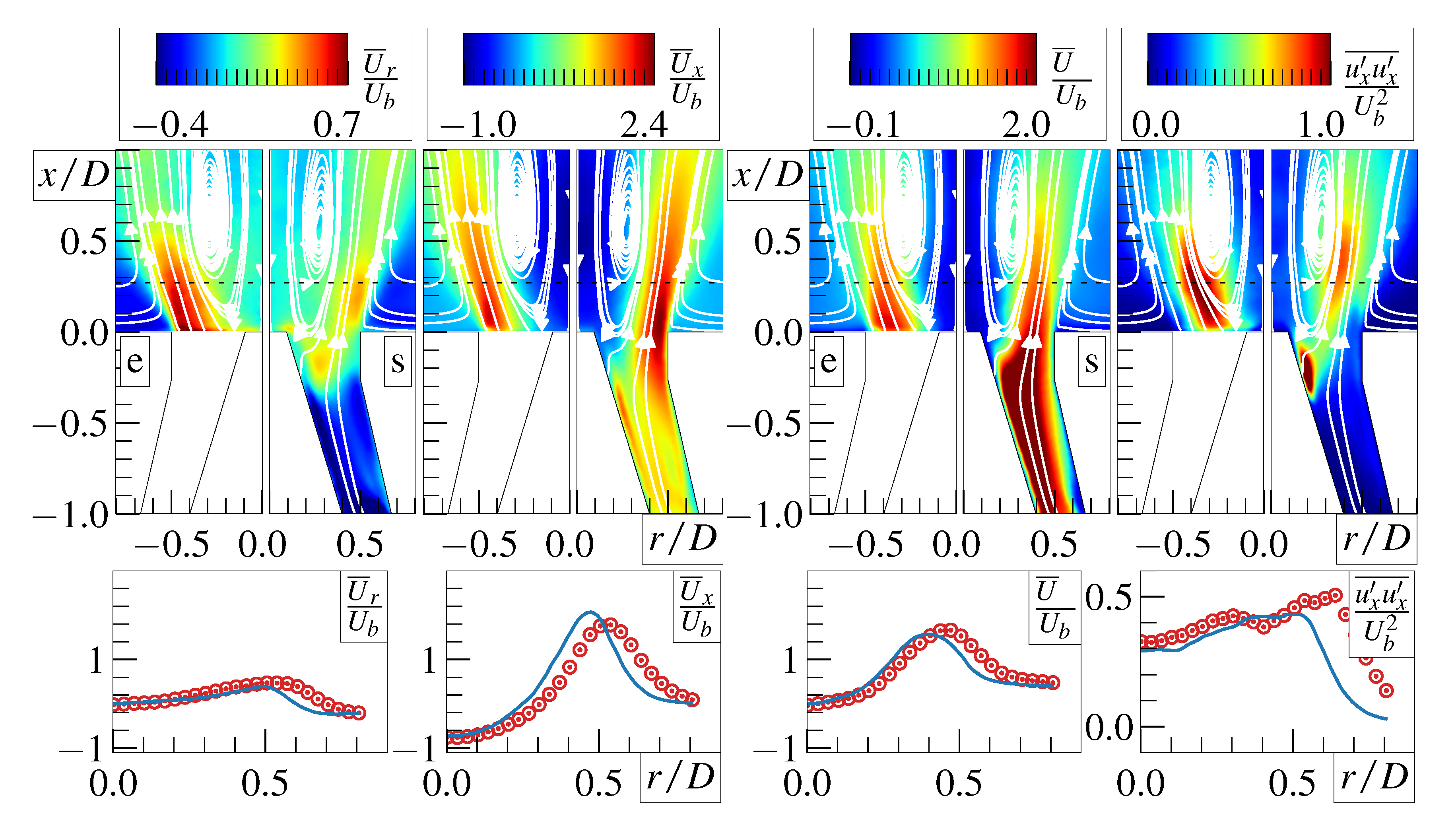
Figure 3 shows the results of the mesh convergence study for isothermal and reacting cases without the central jet. The coarse mesh m 1 contained 4.2 × 10⁶ control volumes with approximately 130, 290, and 280 cells in radial, axial, and azimuthal directions. The central area along the symmetry axis was subjected to the highly dense mesh due to central jet effects. The refinement procedure, which splits each hexahedral cell of m 1 in x directions producing 2 smaller hexahedra, was employed in the critical area r / D < 0.8 and 1 < x / D < 1 , including the outer shear layer and part of the domain inside the nozzle. The m 2 mesh contained 5.4 × 10⁶ cells, serving as a compromise between accuracy and overall simulation time. In the same region of interest as above, the m 2 mesh was refined in r and θ directions yielding 4 smaller cells and resulting in a m 3 mesh with 13.4 × 10⁶ cells total. Meshes m 1 and m 2 were used for isothermal mesh convergence studies, while m 2 and m 3 were utilized in reacting flow cases. These computational grids are visualized in Figure 3 (bottom row). Figure 3 (top row) demonstrates a x-r plane in the near-nozzle area, as well as the time-averaged axial velocity fields for the isothermal and reacting cases without the central jet for Cases 1 and 3 documented in Table 1 with the corresponding Fourier transform of the axial velocity signal. Both cases show that neither the size nor shape of the recirculation zone is affected by the refinement procedure indicating mesh convergence of the results. The results for the reacting case are slightly more sensitive to refinement, demonstrating small changes of the flow inside the recirculating region. The Δ x + , Δ y + , Δ z + distributions were computed and showed a gradual decline with mesh refinement levels increasing, with values typically in the range from 1 to 25, reaching their maximum near the outer radius of the swirler nozzle.
As mentioned in the Introduction, the strongly swirling jet is subjected to the formation of PVC, which is analyzed below. However, Figure 3 also shows the Fourier transform of the U x / U b signal in the inner shear layer for Case 1 and 3. The results for the isothermal case show the peak corresponding to PVC with the Strouhal number S t = f D / U b = 0.98 , where f 127 Hz is the typical frequency in the signal. At the same time for the reacting case, the dominant Strouhal number shifts to the value S t 0.33 .

4.2. No Central Jet

First, to validate experimental and numerical results, we show the comparison between PIV and LES for the isothermal case with no central jet (see Case 1 in Table 1). Figure 4 demonstrates close agreement between experiments and simulations, especially for U ¯ x . The field of tangential velocity U ¯ θ agrees well; however, experimental values are slightly lower than numerical ones. The size and shape of the recirculation zone are well reproduced, despite slight discrepancies in U ¯ r at the bottom of the bubble. A comparison of streamwise turbulent fluctuations u x u x ¯ is possible in the view of the experimental error of the measurements, as well as the level of uncertainty due to the inflow conditions. Similar results show other components of Reynolds stresses.
One may inspect the instantaneous velocity and pressure fields for the isothermal case to understand the organization of vortical structures in the flow. Figure 5 shows three velocity components and pressure in the same cross-section as above, together with streamlines. Note that negative axial velocity penetrates the nozzle due to a strong meandering recirculation zone. The streamlines highlight strong vortical structures zigzagging in the inner shear layer.
Figure 6 shows the time-averaged velocity fields and streamwise Reynolds stresses from PIV and LES for the reacting flow regime corresponding to Case 3 (see Table 1). A close agreement is observed for U ¯ x , U ¯ θ , while the radial velocity for PIV is notably higher than for LES. Turbulent stresses distribution have better agreement near the swirler nozzle. Nevertheless, streamlines for LES and PIV have similar patterns and the size of the recirculation zone agrees well. In line with the isothermal results, we inspect the instantaneous velocity and pressure fields for reactive flow without a strong central jet. Figure 7 shows the three velocity components and pressure highlighting the effect of combustion on the flow. Note a strong acceleration of the velocity fields as well as the laminarization of shear layers. However, the streamlines still indicate a zigzagging large-scale vortical structure in the inner shear layer.

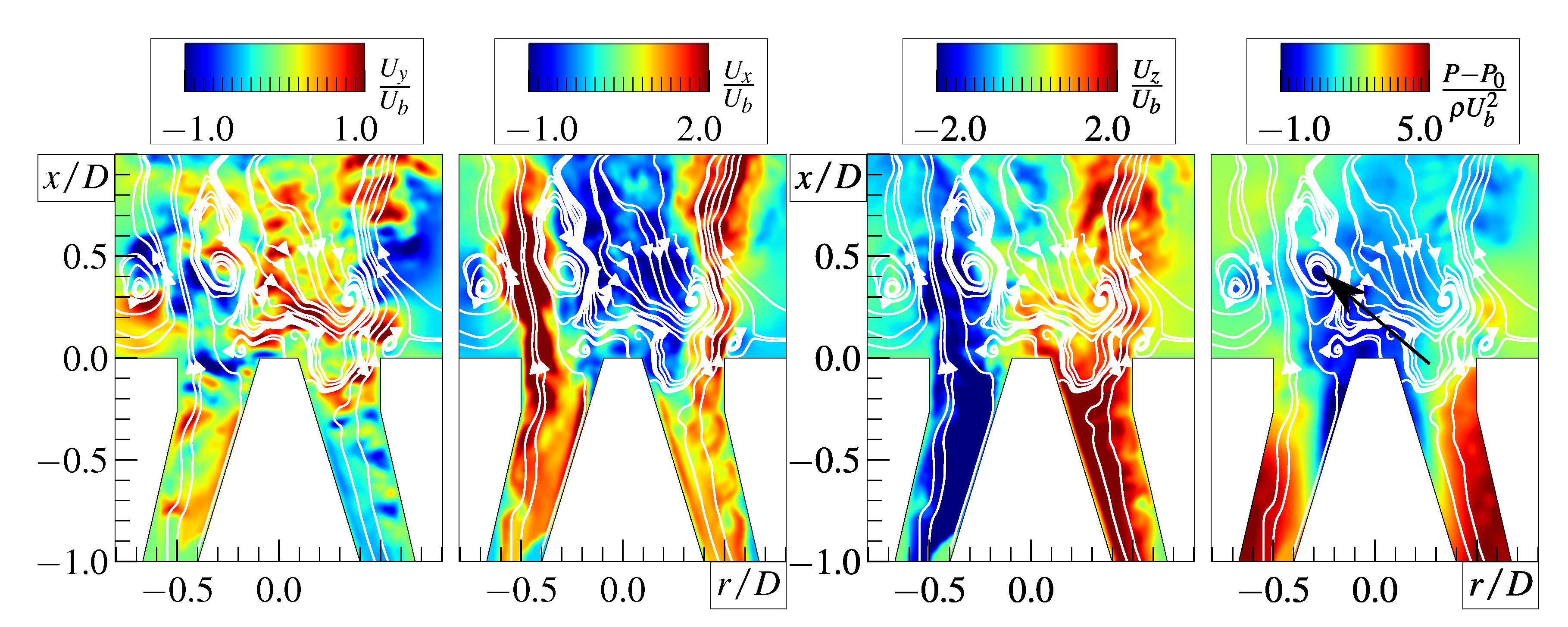
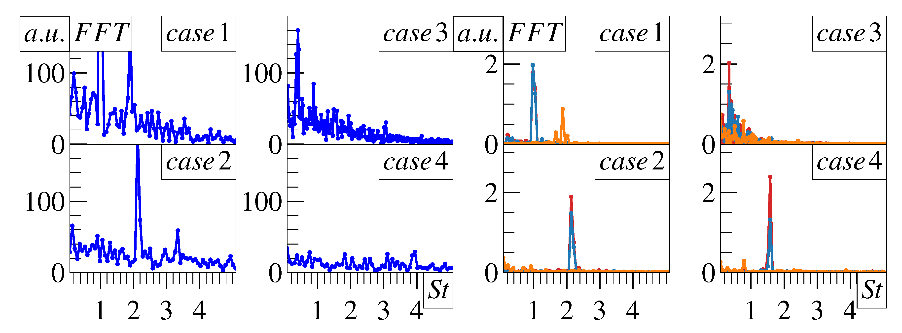
4.3. Central Jet Effect

In this subsection, we assess the effect of the central jet on the time-averaged, instantaneous, and spectral characteristics. Figure 8 compares the axial velocity fields of all four cases. In the case of isothermal flow, the central jet penetrates the bubble, although it is decaying already at x / D = 1 . A long bubble induced by a central bluff body is altered and replaced by a smaller secondary recirculation region attached to the nozzle spanning in the region 0.1 < r / D < 0.3 . However, negative axial velocity areas are still present inside the nozzle together with intensive vortical structures which are analyzed below. At the same time, the comparison of the reacting Cases 3 and 4 shows that the strong central jet largely impacts the recirculation zone vanishing the regions with negative axial velocity. Due to chemical reactions, the presence of lightweight combustion products in the bubble let the jet strongly penetrate along the axis of symmetry. The PVC is expected to be suppressed, leaving smaller spiralling vortices due to a strong swirl in the inner shear layer.
Figure 9 shows the isosurfaces of the pressure field for all isothermal and reacting cases. This visualization reveals a large-scale coherent vortical structure, revealing that the PVC is present mostly in the inner shear layer for Cases 1 and 3, while it is mainly present between inner and outer jets for Cases 2 and 4. This spiralling vortex rotates around the symmetry axis with the bulk swirl according to the non-dimensional frequency S t 0.98 and 0.4 for Case 1 and Case 3, respectively. Spectral analysis indicates that the central jet shifts the dominant frequency to higher values. We may speculate that, since the Strouhal number doubles for Case 1 and 2, a low azimuthal wavenumber m = 1 , which is significant for Case 1, becomes less energetic for the case with the central jet (Case 2), where m = 2 becomes the dominant one. A similar shift takes place in the case of reactive flow regimes.

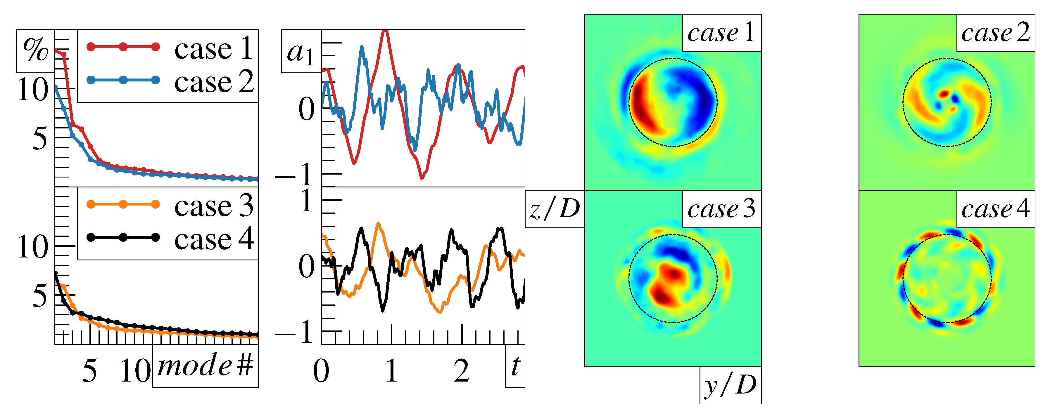
4.4. Proper Orthogonal Decomposition

In this subsection, we perform the proper orthogonal decomposition [72] of the velocity field for all four cases to quantify the contribution of the dominant vortical structures to the overall turbulent fluctuations. The velocity field can be decomposed as follows:
U i ( x , y , z , t ) = k = 1 N a k ( t ) λ k Φ k , i ( x , y , z ) ,
where a k describes the evolution of the mode k, the eigenvalue λ k is the corresponding turbulent kinetic energy, and Φ k , i are the components of a particular eigenmode, see [73,74]. Both a k and Φ k , i are orthonormal basis functions with corresponding normalization. The procedure is performed using the standard SVD decomposition [75].
We perform POD in x-r and r- θ planes for all four cases. For brevity, we summarize the results for r- θ plane at x / D 0.4 , as it is useful to demonstrate cross-planes with a footprint of a spiralling vortical structure. Figure 10 presents an FFT plot of the first 3 POD temporal modes and U x / U b time-signal as in Figure 3 for each case. For Cases 1, 2, 3, and 4, the main frequencies of the first temporal POD mode are S t = 0.98 , 2.13, 0.40, and 1.58, respectively. For Cases 1 and 3, these values are close to the ones previously shown and discussed in Figure 3. This suggests that the POD method correctly captured low-dimensional dynamics of PVC. Figure 11 shows the comparison of POD spectra among all the cases, as well as the first eigenmodes corresponding to the largest eigenvalue. The comparison of isothermal cases show that without the central jet (Case 1), the dominant mode corresponding to the PVC with the azimuthal wavenumber m = 1 contains approximately 27.3 % (the sum of the first two eigenvalues) of the turbulent kinetic energy in the chosen cross-section. The second pair (the sum of the third and fourth eigenvalues) contains around 12.2 % and corresponds to the azimuthal wavenumber m = 2 . On the other hand, with the central jet (Case 2), the dominant eigenvalues are not quite explicit. Moreover, we observe a switch between m = 1 and m = 2 modes. This is in line with recent observations of the competition between the first and second azimuthal wavenumbers for an annular jet [76]. The first two eigenvalues corresponding to m = 2 account for 18.1 % of the total energy. The second pair reflecting m = 1 contains 9.5 %. The dominant frequency of the first temporal POD mode for Case 2 can be observed in the spectra of U x / U b for the case without the central jet as well (see Case 1 in Figure 10). This additionally confirms the switch from m = 1 to m = 2 azimuthal modes for Case 2. A similar analysis of reacting cases shows that without the central jet (Case 3), the first two eigenvalues correspond to m = 1 with 12.2 % of the total energy, while the second pair has 6.6 % presenting m = 2 . In Case 4, the central jet destroys large-scale coherence, leading to dominant higher-frequency fluctuations. The first pair of eigenvalues contains 11.6 % of the total energy, corresponding to a much higher azimuthal wavenumber ( m = 6 ), whereas the second pair has 6.3 % ( m = 3 ). The main frequency of the temporal POD mode in Case 4 is not that pronounced in the spectra of U x / U b for the case without the central jet (see Case 3 in Figure 10) as it was for Cases 1 and 2. This, nevertheless, implies that the flow is substantially modified by the central jet and azimuthal modes m = 1 and m = 2 in Case 3 are no longer present in Case 4, promoting higher azimuthal waves ( m = 3 and m = 6 ).

5. Conclusions

We conducted experimental and numerical simulations and presented results on reacting flow dynamics in a model combustion chamber based on Turbomeca swirler configuration with D = 37   m m by Large-eddy simulations (LES) and Particle image velocimetry (PIV) at the Reynolds number R e = 15,000. We compared four regimes of strongly swirling flow, assessing the effect of the central jet for isothermal and lean reacting conditions. The results of LES are consistent with PIV, particularly for isothermal conditions. We studied dynamic characteristics of the flow and observed intensive spiralling vortical structures, including the precessing vortex core (PVC). The central jet slightly changed the PVC dynamics in the isothermal case where a strong recirculation zone was formed. Nonetheless, for the reacting case, the bubble was significantly altered with no signs of PVC in the inner shear layer. Additional analysis using the proper orthogonal decomposition (POD) showed that the central jet redistributes the turbulent kinetic energy from the first azimuthal wavenumber to higher harmonics. This means that the global instability seen in Cases 1 and 3 was essentially suppressed, leaving a stable flow and increasing mixing in the shear layer (Cases 2 and 3).

Author Contributions

Conceptualization, methodology, M.Y.H., R.I.M. and L.V.; writing, M.Y.H., E.V.P., R.I.M. and V.M.D.; software, validation and visualization, M.Y.H., E.V.P. and D.A.S.; formal analysis and investigation, M.Y.H., E.V.P., R.I.M., L.V.; experimental data acquisition and processing, D.K.S. and A.S.L. All authors have read and agreed to the published version of the manuscript.

Funding

The study was supported by the Ministry of Science and Higher Education of the Russian Federation (agreement No. 075-15-2020-806).

Institutional Review Board Statement

Not applicable.

Informed Consent Statement

Not applicable.

Data Availability Statement

Not applicable.

Acknowledgments

We acknowledge the computational resources of HPC “Cascade” provided by the Novosibirsk State University and Institute of Thermophysics SB RAS.

Conflicts of Interest

The authors declare no conflict of interest.

Abbreviations

The following abbreviations are used in this manuscript:
PVCPrecessing vortex core
LESLarge-eddy simulation
PIVPartice image velocimetry
PLIFPlanar laser-induced fluorescence
FGMFlamelet-generated manifold
PODProper orthogonal decomposition
(r, θ , x)Cylindrical coordiante system components
(x, y, z)Cartesian coordiante system components
Ddiameter of the swirler nozzle
μ dynamic viscosity
μ t turbulent viscosity
ffrequency in Hz
U b bulk velocity calculated through the swirler nozzle
U b p i l o t bulk velocity calculated through the pilot nozzle
StStrouhal number
Q a i r m a i n volumetric flow rate for air supplied in the air channel
Q f u e l p i l o t volumetric flow rate for fuel supplied in the pilot nozzle
ρ density
u i velocity component
ppressure
Y c progress variable
Zmixture fraction
u ¯ i time-averaged velocity component
u ˜ i Favre-averaged velocity component
R i j subgrid-scale stresses tensor
S c t Schmidt number
mPOD mode
λ m energy in m POD mode

References

  1. Gupta, A.; Lilley, D.; Syred, N. Swirl Flows; Abacus Press: Tunbridge Wells, UK, 1984. [Google Scholar]
  2. Weber, R.; Dugué, J. Combustion accelerated swirling flows in high confinements. Prog. Energy Combust. Sci. 1992, 18, 349–367. [Google Scholar] [CrossRef]
  3. Tacina, R. Combustor technology for future aircraft. In Proceedings of the 26th Joint Propulsion Conference, Orlando, FL, USA, 16–18 July 1990; p. 2400. [Google Scholar]
  4. Correa, S.M. Power generation and aeropropulsion gas turbines: From combustion science to combustion technology. Symp. Int. Combust. 1998, 27, 1793–1807. [Google Scholar] [CrossRef]
  5. Lefebvre, A. Gas Turbine Combustion, 2nd ed.; Taylor & Francis: Philadelphia, PA, USA, 1999. [Google Scholar]
  6. Dunn-Rankin, D. Lean Combustion: Technology and Control; Academic Press: Cambridge, MA, USA, 2011. [Google Scholar]
  7. Lieuwen, T.; Torres, H.; Johnson, C.; Zinn, B. A mechanism of combustion instability in lean premixed gas turbine combustors. J. Eng. Gas Turbines Power 2001, 123, 182–189. [Google Scholar] [CrossRef]
  8. Billant, P.; Chomaz, J.M.; Huerre, P. Experimental study of vortex breakdown in swirling jets. J. Fluid Mech. 1998, 376, 183–219. [Google Scholar] [CrossRef] [Green Version]
  9. Lucca-Negro, O.; O’doherty, T. Vortex breakdown: A review. Prog. Energy Combust. Sci. 2001, 27, 431–481. [Google Scholar] [CrossRef]
  10. Syred, N. A review of oscillation mechanisms and the role of the precessing vortex core (PVC) in swirl combustion systems. Prog. Energy Combust. Sci. 2006, 32, 93–161. [Google Scholar] [CrossRef]
  11. Ruith, M.; Chen, P.; Meiburg, E.; Maxworthy, T. Three-dimensional vortex breakdown in swirling jets and wakes: Direct numerical simulation. J. Fluid Mech. 2003, 486, 331–378. [Google Scholar] [CrossRef] [Green Version]
  12. Akhmetov, D.; Nikulin, V.; Petrov, V. Experimental study of self-oscillations developing in a swirling-jet flow. Fluid Dyn. 2004, 39, 406–413. [Google Scholar] [CrossRef]
  13. Oberleithner, K.; Sieber, M.; Nayeri, C.N.; Paschereit, C.O.; Petz, C.; Hege, H.C.; Noack, B.R.; Wygnanski, I. Three-dimensional coherent structures in a swirling jet undergoing vortex breakdown: Stability analysis and empirical mode construction. J. Fluid Mech. 2011, 679, 383–414. [Google Scholar] [CrossRef] [Green Version]
  14. Oberleithner, K.; Paschereit, C.O.; Seele, R.; Wygnanski, I. Formation of turbulent vortex breakdown: Intermittency, criticality, and global instability. AIAA J. 2012, 50, 1437–1452. [Google Scholar] [CrossRef]
  15. Cala, C.; Fernandes, E.; Heitor, M.; Shtork, S. Coherent structures in unsteady swirling jet flow. Exp. Fluids 2006, 40, 267–276. [Google Scholar] [CrossRef]
  16. Alekseenko, S.; Dulin, V.; Kozorezov, Y.S.; Markovich, D. Effect of high-amplitude forcing on turbulent combustion intensity and vortex core precession in a strongly swirling lifted propane/air flame. Combust. Sci. Technol. 2012, 184, 1862–1890. [Google Scholar] [CrossRef]
  17. Oberleithner, K.; Paschereit, C.O.; Wygnanski, I. On the impact of swirl on the growth of coherent structures. J. Fluid Mech. 2014, 741, 156–199. [Google Scholar] [CrossRef] [Green Version]
  18. McManus, K.; Poinsot, T.; Candel, S.M. A review of active control of combustion instabilities. Prog. Energy Combust. Sci. 1993, 19, 1–29. [Google Scholar] [CrossRef]
  19. Lieuwen, T.C. Unsteady Combustor Physics; Cambridge University Press: Cambridge, UK, 2021. [Google Scholar]
  20. Moeck, J.P.; Bourgouin, J.F.; Durox, D.; Schuller, T.; Candel, S. Nonlinear interaction between a precessing vortex core and acoustic oscillations in a turbulent swirling flame. Combust. Flame 2012, 159, 2650–2668. [Google Scholar] [CrossRef]
  21. Oberleithner, K.; Schimek, S.; Paschereit, C.O. Shear flow instabilities in swirl-stabilized combustors and their impact on the amplitude dependent flame response: A linear stability analysis. Combust. Flame 2015, 162, 86–99. [Google Scholar] [CrossRef]
  22. Terhaar, S.; Ćosić, B.; Paschereit, C.; Oberleithner, K. Suppression and excitation of the precessing vortex core by acoustic velocity fluctuations: An experimental and analytical study. Combust. Flame 2016, 172, 234–251. [Google Scholar] [CrossRef]
  23. Ghani, A.; Poinsot, T.; Gicquel, L.; Müller, J.D. LES study of transverse acoustic instabilities in a swirled kerosene/air combustion chamber. Flow Turbul. Combust. 2016, 96, 207–226. [Google Scholar] [CrossRef] [Green Version]
  24. Stöhr, M.; Arndt, C.M.; Meier, W. Transient effects of fuel–air mixing in a partially-premixed turbulent swirl flame. Proc. Combust. Inst. 2015, 35, 3327–3335. [Google Scholar] [CrossRef] [Green Version]
  25. Terhaar, S.; Krüger, O.; Paschereit, C.O. Flow field and flame dynamics of swirling methane and hydrogen flames at dry and steam diluted conditions. J. Eng. Gas Turbines Power 2015, 137, 041503. [Google Scholar] [CrossRef]
  26. Reynolds, W.; Alonso, J.; Fatica, M. Aircraft gas turbine engine simulations. In Proceedings of the 16th AIAA Computational Fluid Dynamics Conference, Orlando, FL, USA, 23–26 June 2003; p. 3698. [Google Scholar]
  27. Stricker, W.P. Measurement of Temperature in Laboratory Flames and Practical Devices; Taylor and Francis: New York, NY, USA, 2002. [Google Scholar]
  28. Meier, W.; Duan, X.R.; Weigand, P.; Lehmann, B. Temperatur-Messungen in turbulenten Drallflammen: Thermoelemente im Vergleich zu Laser-Raman-Streuung. Gas Wärme Int. 2004, 53, 153–158. [Google Scholar]
  29. Stöhr, M.; Sadanandan, R.; Meier, W. Experimental study of unsteady flame structures of an oscillating swirl flame in a gas turbine model combustor. Proc. Combust. Inst. 2009, 32, 2925–2932. [Google Scholar] [CrossRef]
  30. Boxx, I.; Stöhr, M.; Carter, C.; Meier, W. Temporally resolved planar measurements of transient phenomena in a partially pre-mixed swirl flame in a gas turbine model combustor. Combust. Flame 2010, 157, 1510–1525. [Google Scholar] [CrossRef] [Green Version]
  31. Midgley, K.; Spencer, A.; McGuirk, J. Unsteady flow structures in radial swirler fed fuel injectors. J. Eng. Gas Turbines Power 2005, 127, 755–764. [Google Scholar] [CrossRef]
  32. Spencer, A.; McGuirk, J.; Midgley, K. Vortex breakdown in swirling fuel injector flows. J. Eng. Gas Turbines Power 2008, 130, 021503. [Google Scholar] [CrossRef]
  33. Kim, W.W.; Menon, S.; Mongia, H.C. Large-eddy simulation of a gas turbine combustor flow. Combust. Sci. Technol. 1999, 143, 25–62. [Google Scholar] [CrossRef]
  34. Selle, L.; Lartigue, G.; Poinsot, T.; Koch, R.; Schildmacher, K.U.; Krebs, W.; Prade, B.; Kaufmann, P.; Veynante, D. Compressible large eddy simulation of turbulent combustion in complex geometry on unstructured meshes. Combust. Flame 2004, 137, 489–505. [Google Scholar] [CrossRef]
  35. Duwig, C.; Fuchs, L. Large eddy simulation of vortex breakdown/flame interaction. Phys. Fluids 2007, 19, 075103. [Google Scholar] [CrossRef]
  36. Dunham, D.; Spencer, A.; McGuirk, J.; Dianat, M. Comparison of URANS and LES CFD methodologies for air swirl fuel injectors. Turbo Expo Power Land Sea Air 2008, 43130, 187–196. [Google Scholar]
  37. Moureau, V.; Domingo, P.; Vervisch, L. From large-eddy simulation to direct numerical simulation of a lean premixed swirl flame: Filtered laminar flame-pdf modeling. Combust. Flame 2011, 158, 1340–1357. [Google Scholar] [CrossRef]
  38. Paschereit, C.O.; Gutmark, E.; Weisenstein, W. Structure and control of thermoacoustic instabilities in a gas-turbine combustor. Combust. Sci. Technol. 1998, 138, 213–232. [Google Scholar] [CrossRef]
  39. Paschereit, C.O.; Gutmark, E.; Weisenstein, W. Coherent structures in swirling flows and their role in acoustic combustion control. Phys. Fluids 1999, 11, 2667–2678. [Google Scholar] [CrossRef]
  40. Paschereit, C.O.; Gutmark, E.; Weisenstein, W. Excitation of thermoacoustic instabilities by interaction of acoustics and unstable swirling flow. AIAA J. 2000, 38, 1025–1034. [Google Scholar] [CrossRef]
  41. Külsheimer, C.; Büchner, H. Combustion dynamics of turbulent swirling flames. Combust. Flame 2002, 131, 70–84. [Google Scholar] [CrossRef]
  42. Balachandran, R.; Ayoola, B.; Kaminski, C.; Dowling, A.; Mastorakos, E. Experimental investigation of the nonlinear response of turbulent premixed flames to imposed inlet velocity oscillations. Combust. Flame 2005, 143, 37–55. [Google Scholar] [CrossRef]
  43. Bellows, B.D.; Neumeier, Y.; Lieuwen, T. Forced response of a swirling, premixed flame to flow disturbances. J. Propuls. Power 2006, 22, 1075–1084. [Google Scholar] [CrossRef]
  44. Bellows, B.D.; Bobba, M.K.; Forte, A.; Seitzman, J.M.; Lieuwen, T. Flame transfer function saturation mechanisms in a swirl-stabilized combustor. Proc. Combust. Inst. 2007, 31, 3181–3188. [Google Scholar] [CrossRef]
  45. Giauque, A.; SELLE, L.; Gicquel, L.; Poinsot, T.; Buechner, H.; Kaufmann, P.; Krebs, W. System identification of a large-scale swirled partially premixed combustor using LES and measurements. J. Turbul. 2005, 6, N21. [Google Scholar] [CrossRef]
  46. Kang, D.; Culick, F.; Ratner, A. Combustion dynamics of a low-swirl combustor. Combust. Flame 2007, 151, 412–425. [Google Scholar] [CrossRef]
  47. Lacarelle, A.; Faustmann, T.; Greenblatt, D.; Paschereit, C.; Lehmann, O.; Luchtenburg, D.; Noack, B. Spatiotemporal characterization of a conical swirler flow field under strong forcing. J. Eng. Gas Turbines Power 2009, 131, 031504. [Google Scholar] [CrossRef] [Green Version]
  48. Ayoola, B.; Hartung, G.; Armitage, C.; Hult, J.; Cant, R.; Kaminski, C. Temperature response of turbulent premixed flames to inlet velocity oscillations. Exp. Fluids 2009, 46, 27–41. [Google Scholar] [CrossRef]
  49. Thumuluru, S.K.; Lieuwen, T. Characterization of acoustically forced swirl flame dynamics. Proc. Combust. Inst. 2009, 32, 2893–2900. [Google Scholar] [CrossRef]
  50. Kim, K.T.; Lee, J.G.; Quay, B.; Santavicca, D. Response of partially premixed flames to acoustic velocity and equivalence ratio perturbations. Combust. Flame 2010, 157, 1731–1744. [Google Scholar] [CrossRef]
  51. Kim, K.T.; Hochgreb, S. The nonlinear heat release response of stratified lean-premixed flames to acoustic velocity oscillations. Combust. Flame 2011, 158, 2482–2499. [Google Scholar] [CrossRef]
  52. Palies, P.; Durox, D.; Schuller, T.; Candel, S. The combined dynamics of swirler and turbulent premixed swirling flames. Combust. Flame 2010, 157, 1698–1717. [Google Scholar] [CrossRef]
  53. Palies, P.; Schuller, T.; Durox, D.; Gicquel, L.; Candel, S. Acoustically perturbed turbulent premixed swirling flames. Phys. Fluids 2011, 23, 037101. [Google Scholar] [CrossRef] [Green Version]
  54. Kim, K.T.; Santavicca, D. Generalization of turbulent swirl flame transfer functions in gas turbine combustors. Combust. Sci. Technol. 2013, 185, 999–1015. [Google Scholar] [CrossRef]
  55. Sharaborin, D.K.; Savitskii, A.G.; Bakharev, G.Y.; Lobasov, A.S.; Chikishev, L.M.; Dulin, V.M. PIV/PLIF investigation of unsteady turbulent flow and mixing behind a model gas turbine combustor. Exp. Fluids 2021, 62, 1–19. [Google Scholar] [CrossRef]
  56. Janus, B.; Dreizler, A.; Janicka, J. Experimental study on stabilization of lifted swirl flames in a model GT combustor. Flow Turbul. Combust. 2005, 75, 293–315. [Google Scholar] [CrossRef]
  57. Raffel, M.; Willert, C.; Kompenhans, J.; Werely, S. Particle Image Velocimetry. A Practical Guide, 2nd ed.; Springer: Berlin, Germany, 2007. [Google Scholar]
  58. Alekseenko, S.; Dulin, V.; Kozorezov, Y.; Markovich, D.; Shtork, S.; Tokarev, M. Flow structure of swirling turbulent propane flames. Flow Turbul. Combust. 2011, 87, 569–595. [Google Scholar] [CrossRef]
  59. Dulin, V.; Lobasov, A.; Chikishev, L.; Markovich, D.; Hanjalic, K. On impact of helical structures on stabilization of swirling flames with vortex breakdown. Flow Turbul. Combust. 2019, 103, 887–911. [Google Scholar] [CrossRef]
  60. Markovich, D.; Dulin, V.; Abdurakipov, S.; Kozinkin, L.; Tokarev, M.; Hanjalić, K. Helical modes in low- and high-swirl jets measured by tomographic PIV. J. Turbul. 2016, 17, 678–698. [Google Scholar] [CrossRef]
  61. Lobasov, A.; Alekseenko, S.; Markovich, D.; Dulin, V. Mass and momentum transport in the near field of swirling turbulent jets. Effect of swirl rate. Int. J. Heat Fluid Flow 2020, 83, 108539. [Google Scholar] [CrossRef]
  62. Scarano, F. Iterative image deformation methods in PIV. Meas. Sci. Technol. 2001, 13, R1. [Google Scholar] [CrossRef]
  63. Soloff, S.M.; Adrian, R.J.; Liu, Z.C. Distortion compensation for generalized stereoscopic particle image velocimetry. Meas. Sci. Technol. 1997, 8, 1441. [Google Scholar] [CrossRef]
  64. Coudert, S.; Schon, J. Back-projection algorithm with misalignment corrections for 2D3C stereoscopic piv. Meas. Sci. Technol. 2001, 12, 1371–1381. [Google Scholar] [CrossRef]
  65. van Oijen, J.; de Goey, L. Modelling of premixed laminar flames using flamelet-generated manifolds. Combust. Sci. Technol. 2000, 161, 113–137. [Google Scholar] [CrossRef] [Green Version]
  66. Ma, L.; Huang, X.; Roekaerts, D. Large Eddy Simulation of CO2 diluted oxy-fuel spray flames. Fuel 2017, 201, 165–175. [Google Scholar] [CrossRef]
  67. Ma, L. Computational Modeling of Turbulent Spray Combustion. Doctoral Thesis, Delft University of Technology, Delft, The Netherlands, 2016. [Google Scholar]
  68. Nicoud, F.; Ducros, F. Subgrid-scale stress modelling based on the square of the velocity gradient tensor. Flow Turbul. Combust. 1999, 62, 183–200. [Google Scholar] [CrossRef]
  69. Cantera (an Open-Source Suite of Tools for Problems Involving Chemical Kinetics, Thermodynamics, and Transport Processes) Home Page. Available online: https://cantera.org/ (accessed on 9 February 2022).
  70. Smith, G.P.; Golden, D.M.; Frenklach, M.; Moriarty, N.W.; Eiteneer, B.; Goldenberg, M.; Bowman, C.T.; Hanson, R.K.; Song, S.; Gardiner, W.C.; et al. GRI-Mech (an Optimized Detailed Chemical Reaction Mechanism Capable of the Best Representation of Natural Gas Flames and Ignition). Home Page. Available online: http://combustion.berkeley.edu/gri-mech/ (accessed on 9 February 2022).
  71. OpenFOAM (Free, Open Source CFD Software with an Extensive Range of Features to Solve Anything from Complex Fluid Flows Involving Chemical Reactions, Turbulence and Heat Transfer, to Acoustics, Solid Mechanics and Electromagnetics) Home Page. 2004. Available online: http://www.openfoam.com (accessed on 9 February 2022).
  72. Holmes, P.; Lumley, J.; Berkooz, G.; Rowley, C.W. Turbulence, Coherent Structures, Dynamical Systems and Symmetry; Cambridge University Press: Cambridge, UK, 2012. [Google Scholar]
  73. Mullyadzhanov, R.; Abdurakipov, S.; Hanjalic, K. Helical structures in the near field of a turbulent pipe jet. Flow Turbul. Combust. 2017, 98, 367. [Google Scholar] [CrossRef]
  74. Mullyadzhanov, R.; Sandberg, R.; Abdurakipov, S.; George, W.; Hanjalić, K. Propagating helical waves as a building block of round turbulent jets. Phys. Rev. Fluids 2018, 3, 062601. [Google Scholar] [CrossRef] [Green Version]
  75. Sirovich, L. Turbulence and the dynamics of coherent structures, I. Coherent structures. Q. Appl. Math. 1987, 45, 561. [Google Scholar] [CrossRef] [Green Version]
  76. Vanierschot, M.; Muller, J.; Sieber, M.; Percin, M.; van Oudheusden, B.; Oberleithner, K. Single-and double-helix vortex breakdown as two dominant global modes in turbulent swirling jet flow. J. Fluid Mech. 2020, 883, A31. [Google Scholar] [CrossRef]
Figure 1. Photograph and 3D sketch of the model gas turbine combustor.
Energies 15 01615 g001
Figure 2. Computational domain of the combustion chamber model and Cartesian and cylindrical coordinate systems.
Energies 15 01615 g002
Figure 3. Cell centers for m 1 and m 2 meshes are demonstrated in the near-nozzle area in the x-r plane. Contour plots in the middle show the time-averaged axial velocity field for the isothermal Case 1 (obtained on m 1 and m 2 ) and reacting Case 3 (obtained on m 2 and m 3 ) (see Table 1). The Fourier transform of the axial velocity U x / U b signal in auxiliary units (a.u.) is presented for Case 1 (red— m 1 , blue— m 2 ) and Case 3 (red— m 2 , blue— m 3 ), measured at 4 points defined as ( x , r ) = ( 0.13 D , 0.40 D ) (distributed by π / 2 along θ direction). The bottom row provides a three-dimensional illustration of m 1 , m 2 , and m 3 meshes.
Energies 15 01615 g003
Figure 4. Experimental (e) and numerical (s) time-averaged velocity components and streamwise component of the Reynolds stresses in the x-r plane for the isothermal case with no central jet (see Case 1 in Table 1). Bottom row presents mean profiles at x / D = 0.27 (LES—solid line, PIV—⊙ markers).
Energies 15 01615 g004
Figure 5. Instantaneous velocity and pressure fields for the isothermal case with no central jet (see Case 1 in Table 1) are presented in the x-r plane to highlight the PVC near the nozzle. We employ Cartesian coordinates, where ( U x , U y , U z ) correspond to the streamwise, ‘radial’ and ‘azimuthal’ components in cylindrical coordinates (see Figure 2). The pressure field P is plotted with respect to the pressure at the origin P 0 .
Energies 15 01615 g005
Figure 6. Experimental (e) and numerical (s) time-averaged velocity components and streamwise component of the Reynolds stresses in the x-r plane for the reacting case with no central jet (see Case 3 in Table 1). Bottom row presents mean profiles at x / D = 0.27 (LES—solid line, PIV—⊙ markers).
Energies 15 01615 g006
Figure 7. Instantaneous velocity and pressure fields for the reacting case with no central jet (see Case 3 in Table 1) are presented in the x-r plane to highlight the PVC near the nozzle. For this image we employ Cartesian coordinates where ( U x , U y , U z ) correspond to the streamwise, ‘radial’, and ‘azimuthal’ components in cylindrical coordinates (see Figure 2). The pressure field P is plotted with respect to the pressure at the origin P 0 .
Energies 15 01615 g007
Figure 8. Comparison of all four cases without and with the central jet. Time-averaged and instantaneous axial velocity field for isothermal and reacting cases.
Energies 15 01615 g008
Figure 9. Pressure field isosurfaces are displayed for all considered cases.
Energies 15 01615 g009
Figure 10. The spectra of (left) U x / U b time history for the same points as in Figure 3 and (right) temporal POD modes # 1 (red), 2 (blue), 3 (orange) for all four cases and in auxiliary units (a.u.).
Energies 15 01615 g010
Figure 11. The left plot shows the part of energy λ i 2 / λ k 2 and time-history a 1 ( t ) of a particular POD mode #i for all cases. The right image demonstrates the spatial distribution of the axial component Φ 1 , x ( y , z ) at the station x / D 0.4 for the largest eigenvalue for all cases. A dashed circle shows the diameter of the nozzle D.
Energies 15 01615 g011
Table 1. Description of flow cases with the corresponding values of air and fuel flow rates [ L / min ] and bulk velocities [ m / s ] .
Case Q air main Q fuel main U b Q air pilot Q fuel pilot U b pilot Type
Case 139804.82000isothermal
Case 239804.8229.2017.18isothermal
Case 339810.84.903.21.91reacting
Case 439810.84.926.03.217.18reacting
Publisher’s Note: MDPI stays neutral with regard to jurisdictional claims in published maps and institutional affiliations.

