Article

A Novel Circulating Current Suppression for Paralleled Current Source Converter Based on Virtual Impedance Concept

1
Electrical Engineering Department, Yanshan University, Qinhuangdao 066000, China
2
Institute of Electrical Engineering, Chinese Academy of Sciences, Beijing 100190, China
3
State Grid Beijing Electric Power Company, Beijing 100031, China
4
State Grid Jiaxing Electric Power Supply Company, Jiaxing 314000, China
5
Department of Energy Technology, Aalborg University, DK-9220 Aalborg, Denmark
*
Author to whom correspondence should be addressed.
Submission received: 6 February 2022 / Revised: 27 February 2022 / Accepted: 5 March 2022 / Published: 7 March 2022
(This article belongs to the Special Issue Modeling, Control and Design of Power Electronics Converters)

Abstract

:
The circulating current is one of the important issues for parallel converters. It affects the system stable operation and degrades the power quality. In order to reduce the circulating current of the parallel converter and reduce the harmonic pollution to the power grid, a new circulating current suppression strategy is proposed for the parallel current source converter without any communication line. This strategy is able to realize the current sharing between parallel modules by changing the external characteristics of the parallel modules to thus suppress the circulating current among the parallel current source converters. The proposed control strategy adopts DC-side droop control and AC-side virtual impedance control. The DC-side droop control is used to generate the reference voltage of each parallel module, while the AC-side virtual impedance is used to the circulating current suppression. We performed a time domain test of the parallel converter, and the results show that the proposed control strategy reduced the RMS circulating current of the parallel converter by 50% and effectively reduced the grid-side current THD while ensuring the stable operation of the converter. The effectiveness of the proposed control strategy was, therefore, verified.

1. Introduction

With the development of economy, the problems of the energy crisis and environmental pollution are becoming increasingly serious. The problem of developing and effectively utilizing new energy is an urgent problem to be solved in the field of power electronics. In the process of further development of power electronic technology, the current source converter has gradually become a research hotspot. Current source converters are used in uninterruptible power supply systems [1], photovoltaic power generation systems [2,3], wind power generation systems [4], multi-electric aircraft power supply systems [5], motor drives [6], modular multi-level converters [7] and others.
With the development of industry and technology, there are higher requirements for the power capacity of power supply equipment. The parallel power supply system of power modules has the advantages of increasing the capacity and reliability of the power system [8,9]. Multiple parallel modules in the parallel system can achieve equal distribution of power, reduce the voltage and current stress of the power switching devices of each module, and can reduce the size of each module, thereby, reducing the costs and increasing the power density.
Due to the differences in the hardware parameters and control parameters of the parallel converter modules, the operating states of the modules in the parallel system cannot be exactly the same, resulting in the current circulating between the modules in the parallel system [10,11,12]. As a result, the current stress of the power switching device increases, resulting in serious distortion of the AC side current of the converter and even damage to the device when the circulating current is large. Therefore, the problem of suppressing the circulating current of the parallel system has become a problem worth noting in the research of parallel power supply.
Different currents of parallel modules lead to circulating currents between parallel modules. Therefore, the current sharing between parallel modules can effectively solve the circulating current problem. For the method of paralleling multiple modules to improve the power level and reliability of a power supply system, the module parallel topology includes a modular multilevel converter (MMC) and a converter with the same modules connected in parallel. The circulating current suppression method of MMC has been extensively studied, and the circulating current suppression strategy based on proportional resonant controller is widely used in MMC.
The strategy proposed in the literature based on a proportional resonance controller can suppress low-frequency harmonic components, such as the second and fourth order, balance the capacitor voltage of the sub-module, and suppress the circulating current [13,14,15,16,17,18]. Reference [19] introduced a 10-stage linearized model-based MMC dynamic research on circulation suppression control. The gain of the circulation suppression control has a significant effect on the overall MMC dynamics. Reference [20] proposed an optimal control method that applies the gray wolf optimizer to a DC-DC boost converter, which can improve the classical proportional-integral-derivative control algorithm.
Reference [21] proposed a control scheme for suppressing circulating current of parallel inverters in island mode, which solves the circulating current problem of parallel inverters when the rated values of distributed generator sets are different. Reference [22] established an isometric calculation model of the casing circulating current of a gas-insulated switchgear with hybrid reactive power compensation equipment and studied the factors affecting the casing circulating current.
The methods of balancing current between parallel converter modules are mainly divided into control methods with communication lines and control methods without communication lines. The control methods with communication lines mainly include centralized control [23,24], master–slave control [25], and decentralized control [26]. Multiple communication lines are used to realize information exchange between modules, which increases the complexity of connecting lines between modules. It is difficult to realize flexible expansion modules.
The control method without a communication line has the advantages of less connecting lines between modules, high reliability, strong anti-interference ability and easy expansion [27,28,29,30,31]. The control methods without communication lines mainly include droop control and virtual impedance control; however, the control accuracy of the droop control method is low, the system dynamic process needs to reset the droop parameters to reasonably allocate the working points, and the control process is complicated [32,33,34,35]. The virtual impedance control without communication line includes the AC side virtual impedance control, which changes the loop impedance of the module through the control loop, thereby, suppressing the circulating current.
The disadvantage is that the calculation of the virtual impedance is complicated. Reference [36] proposed a strategy for suppressing circulating current based on the coordination of AC side droop control and virtual impedance for three-phase current source inverters and uses secondary control to reduce voltage deviation. According to the above investigation of MMC suppression circulating current method and summarizing the scheme of parallel converter suppressing circulating current, provided the idea for this paper to propose a strategy for suppressing circulating current in parallel current source converters.
After the analysis of the parallel module, a control scheme of the virtual impedance on the DC side to suppress the circulating current is obtained. By analyzing the DC equivalent circuit of the parallel module, the factors affecting the circulating current of the parallel system are obtained. In this paper, a parallel current source converter without a communication line is proposed to suppress the circulating current.
The DC side of the proposed scheme adopts droop control to realize parallel current sharing between modules, and the AC side adopts virtual impedance control to realize the suppression of circulating current between modules. We avoid the use of a communication lines between modules. Compared with the existing suppression circulating current strategy, the scheme proposed in this paper has the advantages of simple structure, simple parameter setting, high reliability, easy module expansion, and avoiding communication signal interference.
The Section 2 of this paper introduces the current source converter topology and its control method and control strategy. In the Section 3, the circulating current of the parallel current source converter is modeled and analyzed. By analyzing the DC equivalent circuit model of the parallel current source converter, the mathematical models of the positive DC bus current and the negative DC bus current of the parallel system are obtained, and a parallel current sharing scheme of current source converters without a communication line is proposed.
This scheme adds virtual impedance control on the AC side and designs the virtual impedance according to the parameters of the parallel modules. In the Section 4, the simulation and verification of the virtual impedance-based current source converter current sharing scheme proposed in the Section 3 is conducted. Finally, we present our conclusions.

2. System Operation Principle

The parallel two current source converter system studied in this paper adopts two three-phase current source converters with the same structure in parallel. First, the topology, working principle, control mode, and modulation mode of a single current source converter are introduced. The three-phase current source converter topology is shown in Figure 1. The three-phase bridge arm contains six power switching devices, and each power device is connected in series with a diode to improve the reverse blocking capability. The LC filter on the AC side is used to filter out high-frequency harmonics, and the DC side diode DF provides a freewheeling loop for the inductor current to prevent system overvoltage [37,38,39].

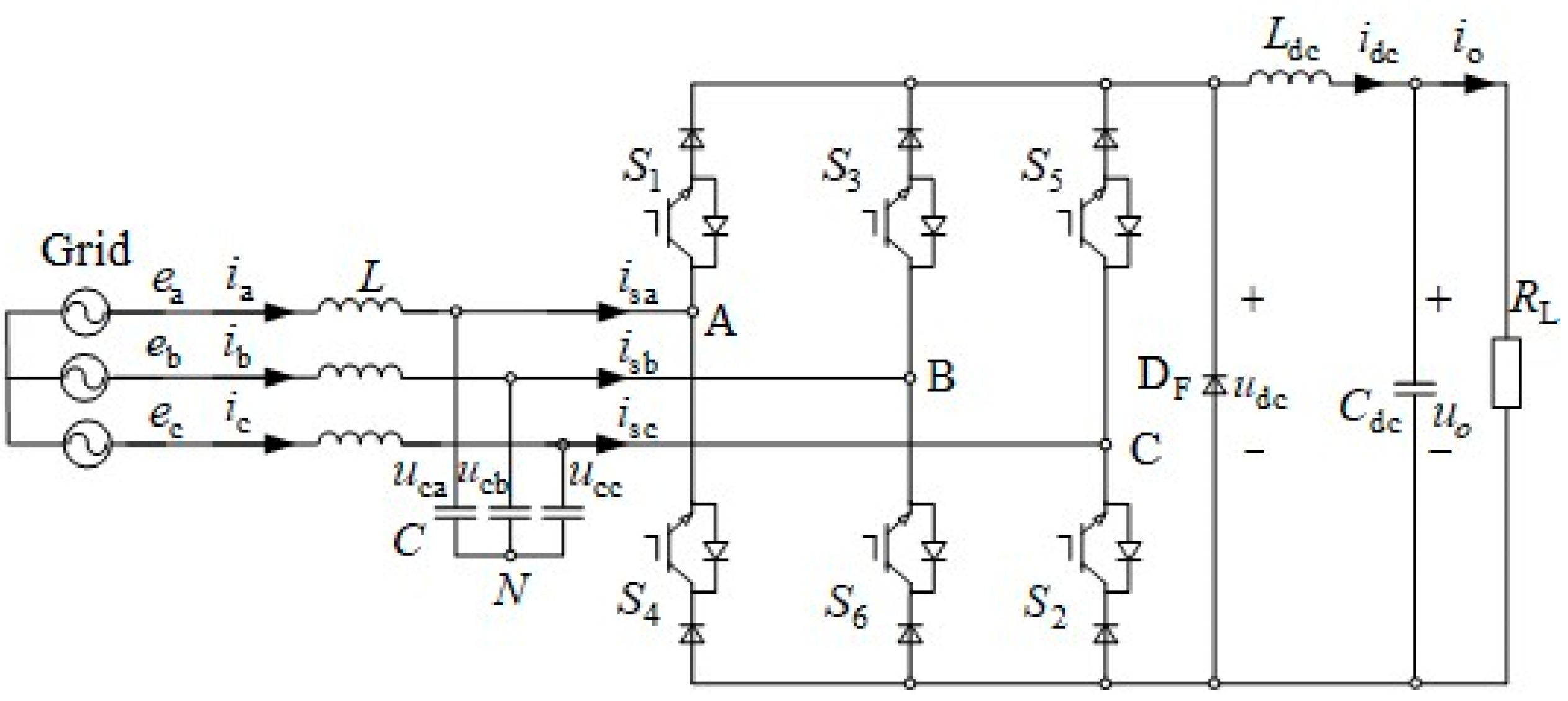
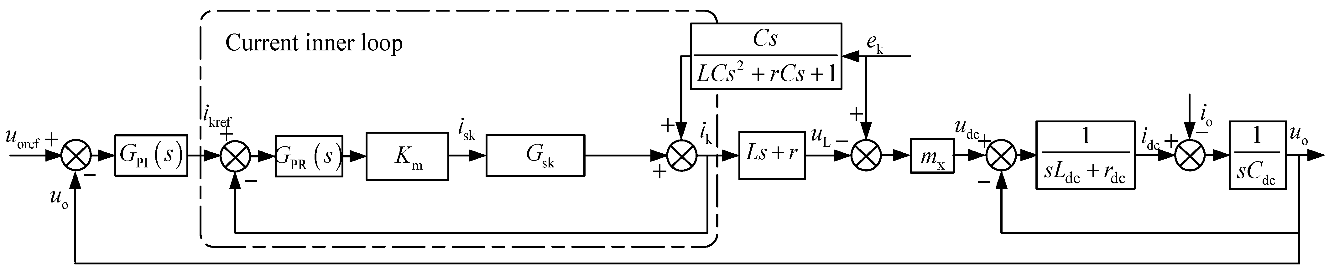
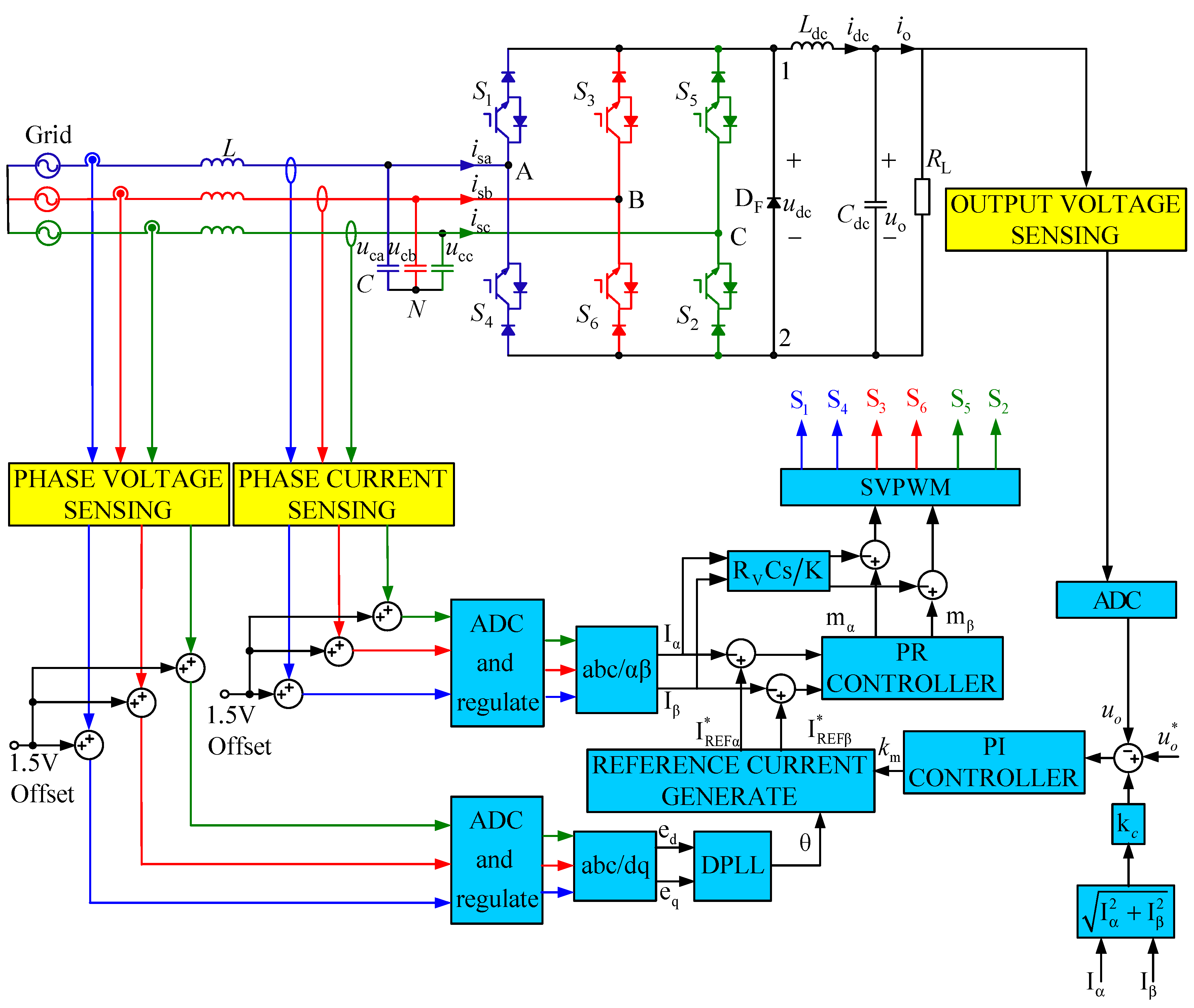
2.1. Conventional Closed-Loop Control Scheme

The conventional control scheme for the PWM converter is the voltage and current double closed-loop control. In order to enable the three-phase current source converter to output sinusoidal grid current and stable DC voltage, the converter adopts the DC side voltage outer loop and the AC side current inner loop. In the double closed-loop control method, the voltage outer loop adopts a PI regulator, and the current inner loop adopts a PR regulator [40,41,42,43,44].
The double closed-loop control block diagram is shown in Figure 2. In order to suppress the current oscillation of the LC filter on the AC side, passive damping schemes and active damping schemes can be used to suppress the LC resonance. The passive damping scheme can suppress the resonance by connecting a damping resistor in series or in parallel with the LC filter. Collect feedback variables and increase control complexity [45,46]. The active damping scheme uses the current or voltage of the inductance or capacitance of the filter as feedback, and the resonance can be suppressed by controlling it [47].

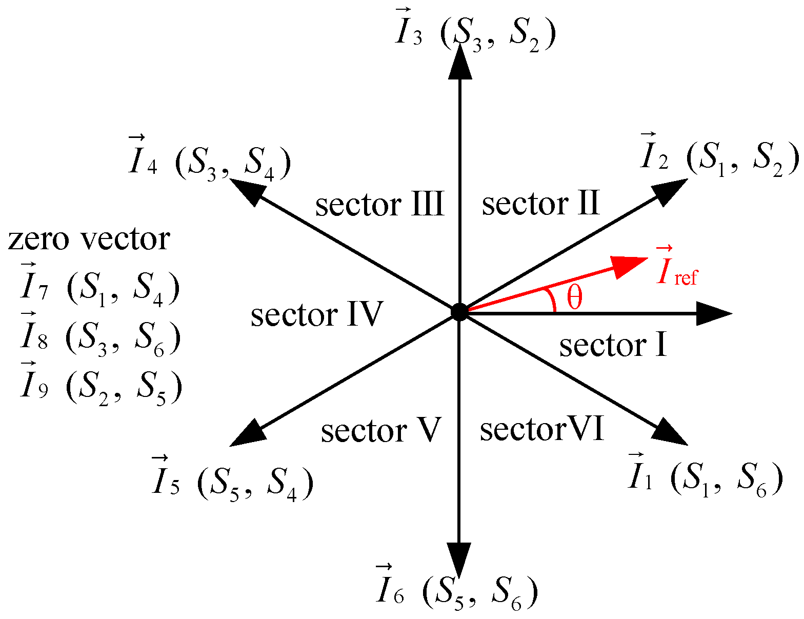
2.2. Space Vector Modulation Strategy

We collect the three-phase input current of the three-phase current source converter and convert the three-phase current from the three-phase static coordinate system to the two-phase static coordinate system through coordinate transformation. At this time, the input current of the current source converter can be equivalent to the rotating vector [48,49,50]. The space vector sector distribution is shown in Figure 3. The current source converter has nine working states, among which there are six active vectors and three zero vectors. The steps of the space vector modulation strategy are the position of the reference vector, the calculation of the vector action time, and the sorting of the vector. To reduce switching losses, the method with the least number of switches is used in each sector.

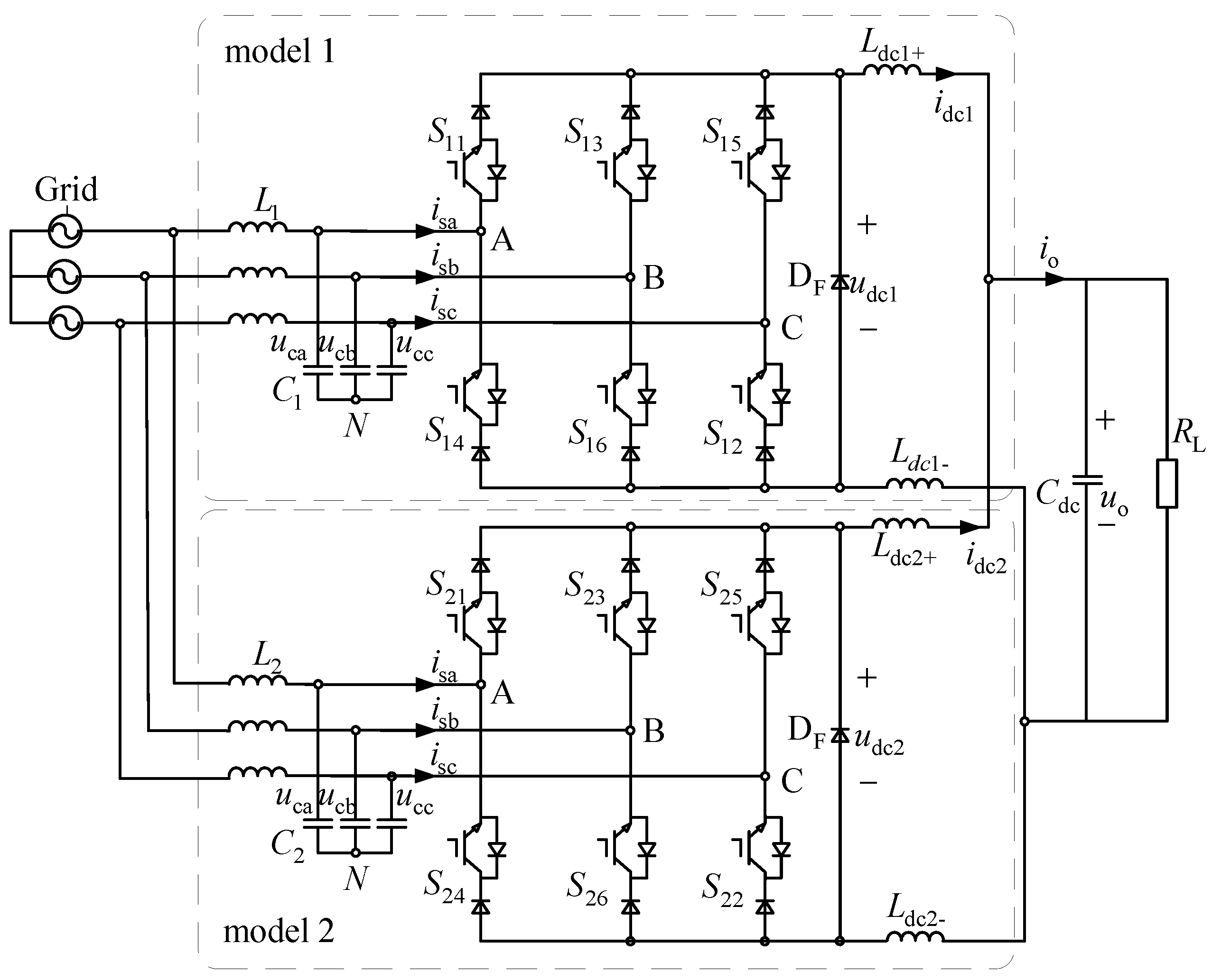
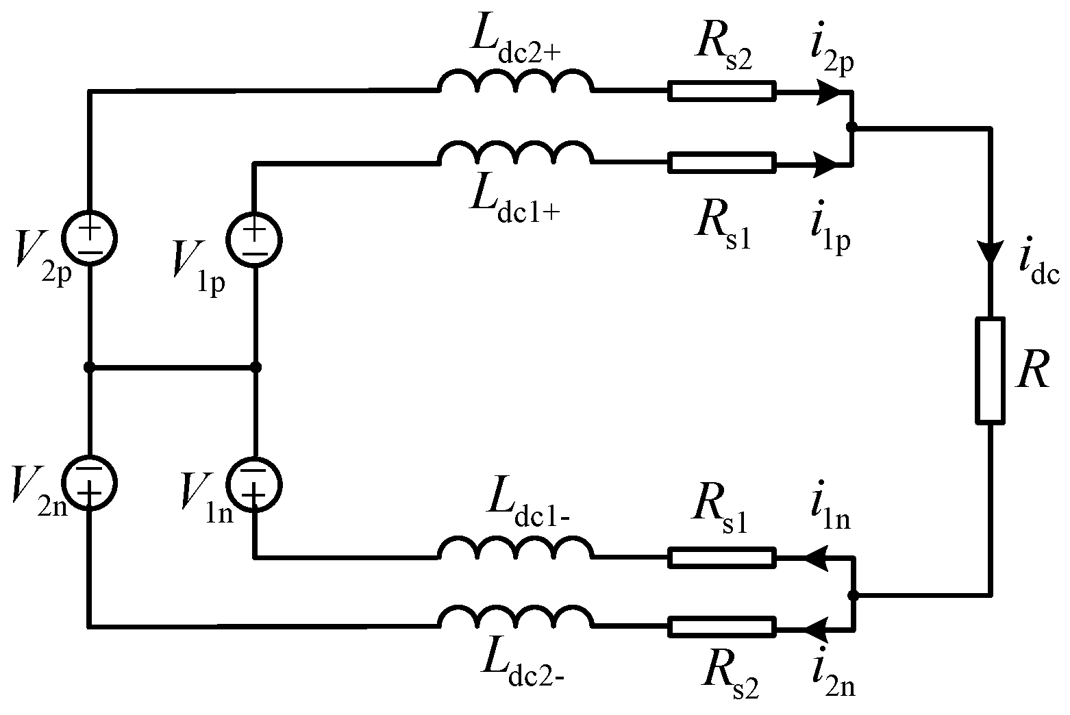
2.3. Parallel Current Source Converter Topology

The AC sides of two current source converter modules are connected in parallel while sharing an AC source, and then the DC sides of the two modules are connected in parallel while sharing a DC filter capacitor to supply power to the same load. The topology of the parallel three-phase current source converter is shown in Figure 4.

3. Circulating Current Suppression Method of Parallel Converters

Before proposing the strategy of suppressing the circulating current, the circulating current of the parallel current source converter is theoretically analyzed, and the mathematical model of the circulating current is established, which provides the basis for the theoretical analysis for the strategy of suppressing the circulating current.

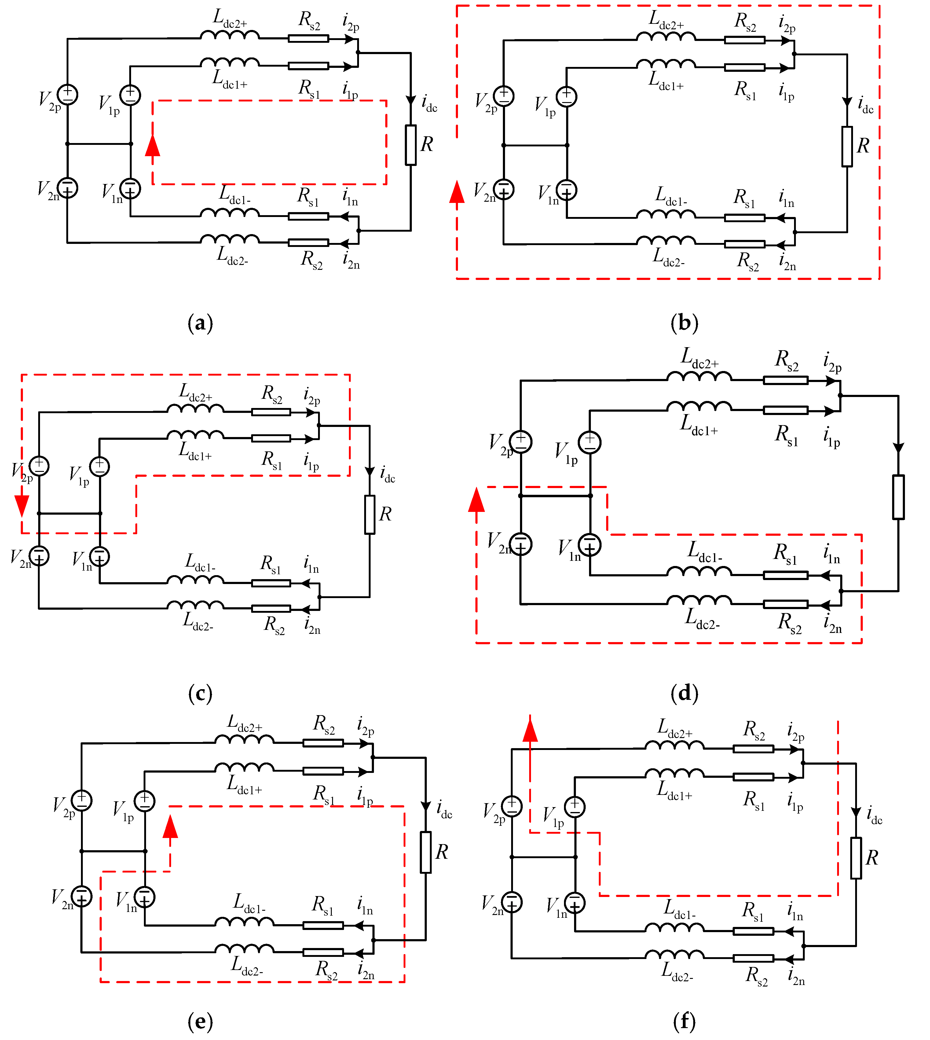
3.1. Circulating Current Analysis of Paralleled Current Source Converters

Figure 5 shows the DC equivalent circuit of the paralleled topology of two current source converters, where V1p and V2p are the output DC positive bus voltages of module 1 and module 2, V1n and V2n are the output DC negative bus voltages of module 1 and module 2, and Rs1 and Rs2 are the equivalent series resistance of the DC filter inductor.
There are six current flow paths of parallel modules, as shown in Figure 6, among which there are four current paths flowing between two parallel modules, as shown in Figure 6c–f. The circulating current is the current that flows only between two parallel modules, and thus the four circulating current paths shown in Figure 6c–f are analyzed.
According to the definition of the circulating current of the paralleled converter, the circulating current is the output voltage difference of the paralleled modules divided by the number of paralleled modules. When the three-phase current source converters are connected in parallel, the circulating current flowing through the positive DC bus of module j is shown in Equation (1), and the circulating current flowing through the negative DC bus of module j is shown in Equation (2).
C j p = m ( i j p i m p ) / N ( j , m = 1 , 2 , 3 , N )
C j n = m ( i j n i m n ) / N ( j , m = 1 , 2 , 3 , N )
We write the loop equation and node voltage equation according to the DC equivalent circuit shown in Figure 4.
L dc 1 + d i 1 p d t + R S 1 i 1 p L dc 2 + d i 2 p d t R S 2 i 2 p = V 1 p V 2 p
L dc 2 d i 2 n d t + R S 2 i 2 n L dc 1 d i 1 n d t R S 1 i 1 n = V 1 n V 2 n
i 2 p + i 1 p = i dc
i 1 n + i 2 n = i d c
Let the differential operator be P, and combine Equations (1) and (2) to calculate the positive DC bus circulating current of module 1 as
C 1 p = V 1 p V 2 p L dc 1 + P + R s 1 + L dc 2 + P + R s 2 + L dc 2 + P + R s 2 L dc 1 + P R s 1 2 ( L dc 1 + P + R s 1 + L dc 2 + P + R s 2 ) × i dc
The negative DC bus circulating current of module 1 is
C 1 n = V 2 n V 1 n L dc 1 - P + R s 1 + L dc 2 - P + R s 2 + L dc 2 - P + R s 2 L dc 1 - P R s 1 2 ( L dc 1 P + R s 1 + L dc 2 - P + R s 2 ) × i dc
Assume that
Z 1 + = L d c 1 + P + R s 1
Z 2 + = L d c 2 + P + R s 2
Z 1 = L d c 1 P + R s 1
Z 2 = L d c 2 P + R s 2
Δ V 1 p = V 1 p V 2 p = ( d 1 ap d 2 ap ) v a + ( d 1 bp d 2 bp ) v b + ( d 1 cp d 2 cp ) v c = Δ d ap v a + Δ d bp v b + Δ d cp v c
Δ V 1 n = V 1 n V 2 n = ( d 1 a n d 2 an ) v a + ( d 1 bn d 2 bn ) v b + ( d 1 cn d 2 cn ) v c = Δ d an v a + Δ d bn v b + Δ d cn v c
Among them, Δdip is the difference between the duty ratios of the switches of the upper bridge arm of the i-phase (i = a, b, c) of the two modules, and Δdin is the difference of the duty ratios of the lower arm switches of the i-phase of the two modules.
Assuming that the input three-phase AC current is balanced, the three-phase AC voltage is expressed in matrix form, and the three-phase static coordinate system is transformed into the rotating coordinate system. Combined with Equations (5) and (6), the converter module 1 in the rotating coordinate system can be obtained. Similarly, the circulation expression of module 2 in the rotating coordinate system can be obtained.
C 1 p = 1 Z 1 + + Z 2 + T [ Δ d ap Δ d bp Δ d cp ] T [ v a v b v c ] + Z 2 + Z 1 + 2 ( Z 1 + + Z 2 + ) × i dc
C 1 n = 1 Z 1 + Z 2 T [ Δ d an Δ d bn Δ d cn ] T [ v a v b v c ] + Z 2 Z 1 2 ( Z 1 + Z 2 ) × i dc
Similarly, the circulation expression of module 2 in the rotating coordinate system can be obtained.
C 2 p = 1 Z 1 + + Z 2 + T [ Δ d ap Δ d bp Δ d cp ] T [ v a v b v c ] + Z 1 + Z 2 + 2 ( Z 1 + + Z 2 + ) × i dc
C 2 n = 1 Z 1 + Z 2 T [ Δ d an Δ d bn Δ d cn ] T [ v a v b v c ] + Z 1 Z 2 2 ( Z 1 + Z 2 ) × i dc
From the above analysis, it can be seen that the factor that generates the circulating current is the difference in the duty cycle of the paralleled modules, and the size of the circulating current path impedance affects the size of the circulating current. The circulating current path impedance includes the current sharing inductance and its equivalent series resistance.
After the above analysis, in order to suppress the circulating current, the control method is adopted to make the positive and negative DC bus impedances of the two paralleled modules equal. Since the size of the inductance and its equivalent series resistance cannot be changed, and increasing the actual resistance will increase the power loss, adding virtual impedance to the control loop can avoid circuit heating and power loss.

3.2. Circulating Current Suppression Method of Parallel Converters

Figure 7 shows the control block diagram of a control strategy for suppressing the circulating current of a parallel three-phase current source converter without communication lines as proposed in this paper.
Each parallel module in the parallel system adopts this control strategy. This kind of parallel converter without communication line suppresses the circulating current control strategy by adopting DC side droop control to obtain the reference output DC voltage of each parallel module, and thus as to achieve the purpose of current sharing control between modules. The virtual impedance control is added on the AC side to change the output characteristics of the converter, and thus that the external characteristics of the parallel modules are close to the same, thereby, suppressing the circulating current. Rv is the virtual impedance, and kc is the droop coefficient.
The relationship between the AC side input current and the DC side current of the three-phase current source converter is related to the switching logic signal δk of the power switching device, and the relationship between the two is shown in Equation (19). Balance, control the three-phase input AC current to reduce the circulating current caused by the parameter difference of the parallel modules, and at the same time reduce the distortion of the AC current measurement of the parallel modules.
i sk = δ k i dc
According to Kirchhoff’s voltage and Kirchhoff’s current law, for the column loop equation and node voltage equation of the three-phase current source converter shown in Figure 1, when the three-phase power grid is symmetrical, the filter capacitance of the LC filter can be obtained. The potential is equal to the midpoint of the three-phase grid. Then, the mathematical model of the three-phase current source converter is transformed into Clarke coordinates, which are converted from the three-phase static coordinate system to the two-phase static coordinate system, and the system order is reduced to obtain the three-phase current source converter and the two-phase static coordinate system. The state equation below is
{ C d u c α β d t = i α β δ α β i dc L d i α β d t = e α β u c α β C dc d u o d t = i dc i o L dc d i dc d t = 3 2 ( δ α u c α + δ β u c β ) u o
The AC side equivalent circuit of the current source converter in the two-phase stationary coordinate system is shown in Figure 8.
The AC side adds a virtual impedance Rv in series with the filter inductor. By controlling the current of the filter capacitor, the input current of the bridge arm of the converter is adjusted, thereby, reducing the current distortion due to the AC side of the converter. The ratio of the voltage uRv of the virtual impedance to the voltage uc across the filter capacitor is 1:K, and the current of the filter capacitor is
i C α β = C d u c α β dt
According to the proportional relationship between the voltage across the virtual impedance and the voltage across the filter capacitor, the current of the filter capacitor after adding the virtual impedance can be obtained as Equation (22). i C α β is the current of the filter capacitor after adding the virtual impedance.
i C α β = R v C P K
The filter capacitor current is used as the feedback amount, and the difference is made with the modulation parameter output by the current inner loop as the modulation signal of the SVPWM generator. By changing the size of the virtual impedance Rv, the loop impedance of the three-phase current source converter module can be changed, thereby, reducing the loop impedance difference between parallel modules. Adding a virtual impedance can change the modulation ratio of the SVPWM generator, thereby, changing the duty ratio of the parallel converter module, which can reduce the difference between the duty ratios of the parallel converter modules.
After the virtual impedance is added to the AC side, the three-phase input voltage on the AC side consists of the voltage across the virtual impedance and the input AC voltage of the three-phase current source converter, and thus the input AC voltage of the three-phase current source converter is expressed as
[ v a v b v c ] = [ v m sin ( ω t ) u R v v m sin ( ω t 120 ) u R v v m sin ( ω t + 120 ) u R v ]
In order to realize current sharing among parallel modules and make the external characteristics of parallel modules consistent, droop control is added on the DC side. Since the sampling period is very short, it can be assumed that the AC side current is constant within a sampling period. There are differences in the external characteristics of parallel modules, resulting in different stable operating points for each module.
By adding droop control on the DC side, the slope of the external characteristic curve can be changed, and thus that the parallel modules can be stabilized at a similar operating point, thereby, reducing the uneven current between the modules caused by the different external characteristics of the DC side of the parallel modules. After adding droop control to each module, it is equivalent to the series resistance of the DC output side, which increases the impedance of the loop.
According to the analysis of the mathematical model of the circulating current of the parallel current source converter in Section 2, the circulating current expression of the parallel module after adding the virtual impedance of the AC side and the droop control of the DC side is obtained. The value of the sag coefficient is 1–2% of the load. Among these, Rd1 is the equivalent droop resistance when module 1 adds droop control, and Rd2 is the equivalent droop resistance when module 2 adds droop control. Among them, Δ d i m (i = a, b, c; m = p, n) is the duty cycle of the converter after adding virtual impedance control.
C 1 p = 1 Z 1 + + R d 1 + Z 2 + + R d 2 T [ Δ d ap Δ d bp Δ d cp ] T [ v a v b v c ] + Z 2 + + R d 2 Z 1 + R d 1 2 ( Z 1 + + R d 1 + Z 2 + + R d 2 ) × i dc
C 1 n = 1 Z 1 + + R d 1 + Z 2 + + R d 2 T [ Δ d an Δ d bn Δ d cn ] T [ v a v b v c ] + Z 2 + + R d 2 Z 1 + R d 1 2 ( Z 1 + + R d 1 + Z 2 + + R d 2 ) × i dc
Similarly, the positive and negative DC bus circulating currents of other parallel modules can be obtained.
C 2 p = 1 Z 1 + R d 1 + Z 2 + R d 2 T [ Δ d ap Δ d bp Δ d cp ] T [ v a v b v c ] + Z 1 + R d 1 Z 2 R d 2 2 ( Z 1 + R d 1 + Z 2 + R d 2 ) × i dc
C 2 n = 1 Z 1 + R d 1 + Z 2 + R d 2 T [ Δ d an Δ d bn Δ d cn ] T [ v a v b v c ] + Z 1 + R d 1 Z 2 R d 2 2 ( Z 1 + R d 1 + Z 2 + R d 2 ) × i dc
From the above modeling analysis of the proposed virtual impedance-based non-communication line parallel current source converter circulating current suppression scheme, it can be obtained that the scheme can reduce the distortion of the AC current by adding a virtual impedance on the AC side, and change the parallel converter. The external characteristics of the module realize the current sharing control on the AC side. Adding droop control to the DC side can realize the current sharing control of the DC side of the parallel converter module.

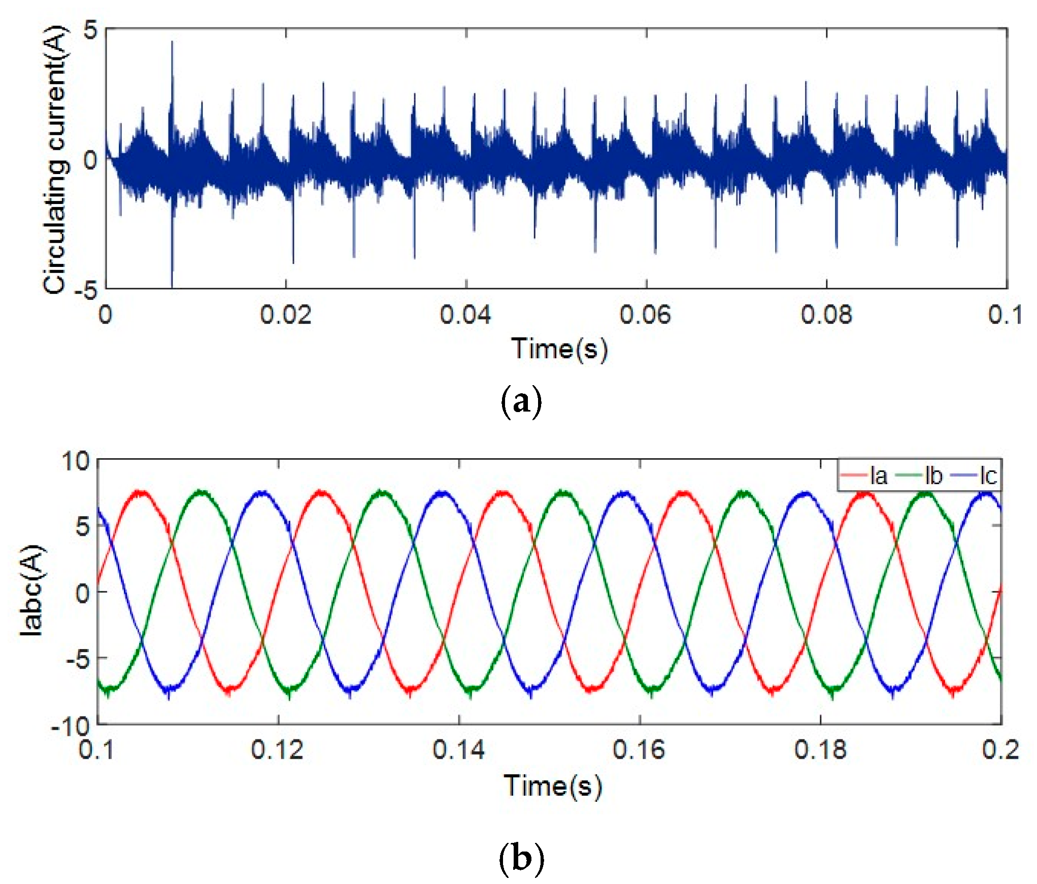
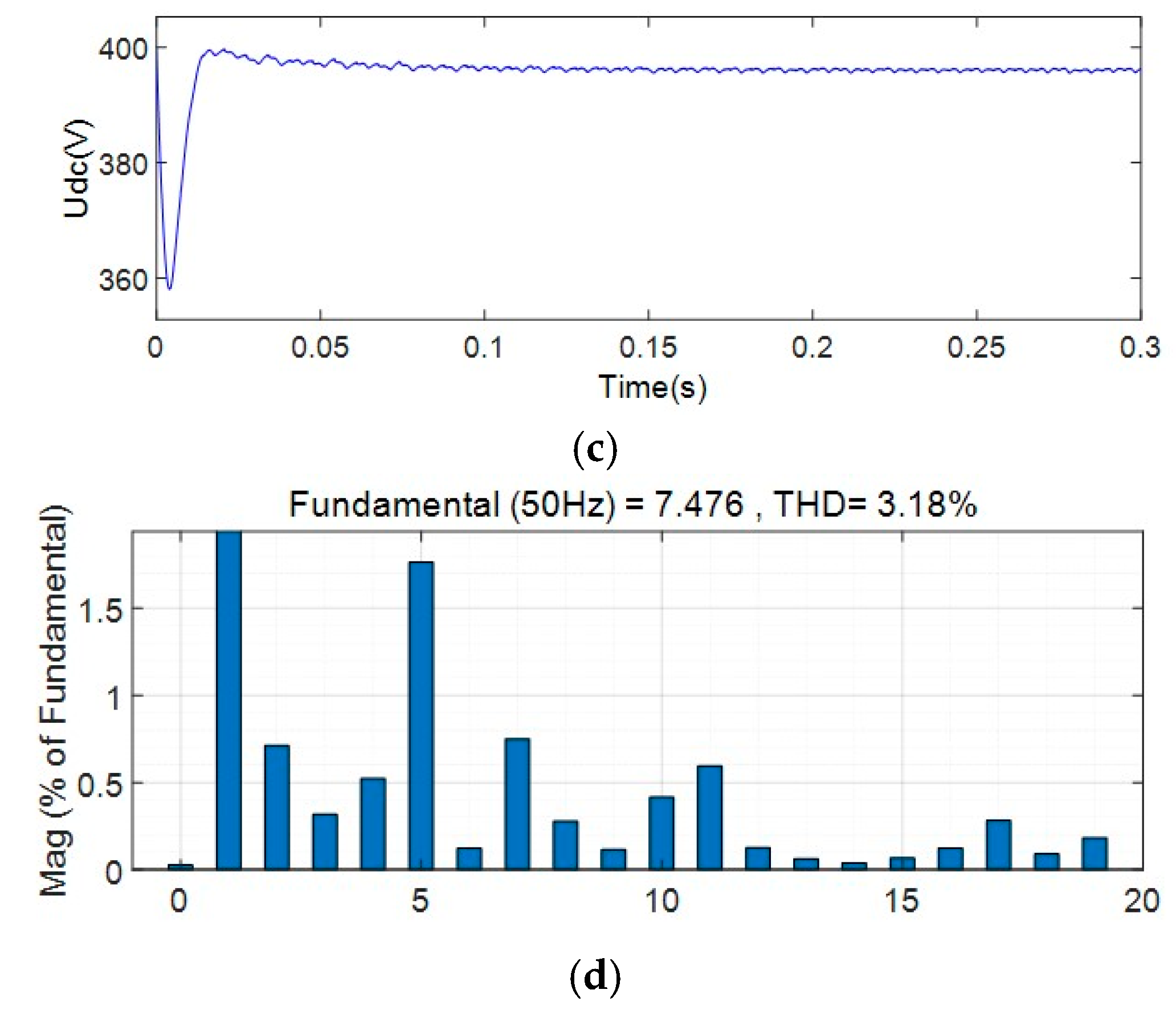
4. Simulation Verification Results

There are many reasons for the difference in the external characteristics of the parallel modules and the asynchronous working state. When the filter inductance or capacitance of the parallel modules is different, the external characteristics of the parallel modules will be different, and the impedance of the circulating current path will increase. If the frequency carrier is out of synchronization, the working state of the parallel modules will be out of synchronization.
In order to verify the effectiveness of the circulating current suppression method for parallel current source converters based on virtual impedance, the parallel current source converter system is analyzed for the following four situations: (1) There are differences in the AC side inductance parameters of the parallel modules. (2) There are differences in the DC side inductance. (3) There are differences in the positive and negative DC bus inductances of a single parallel module.
According to the simulation results, the relationship curves between the virtual impedance and the circulating current, the virtual impedance and the output DC voltage, and the virtual impedance and the AC side current THD are obtained when the parameters of the AC side inductance and the DC side inductance of the parallel module are different. The above four analysis situations are simulated based on the MATLAB/Simulink simulation platform, and the simulation parameters are shown in Table 1.

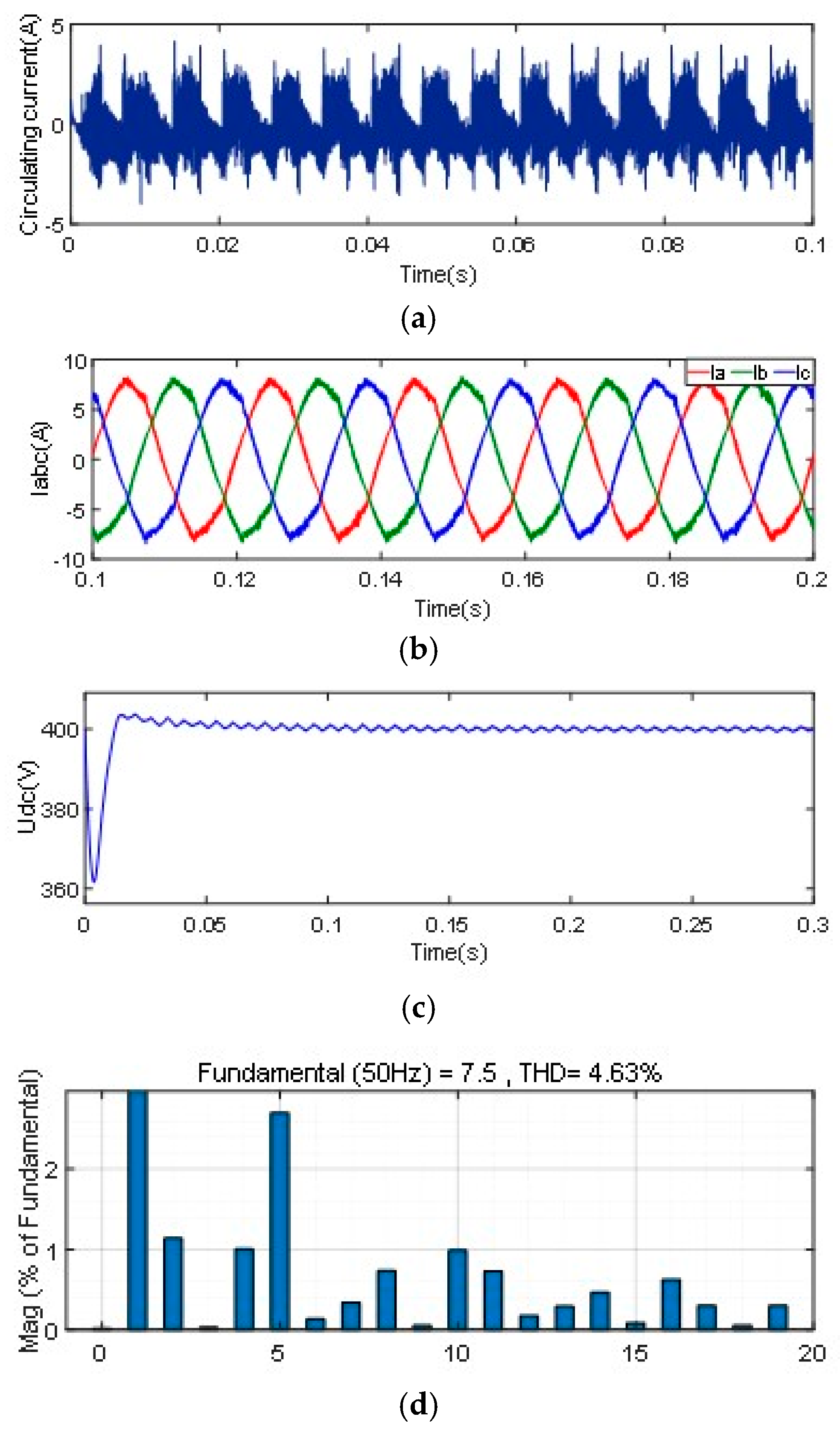
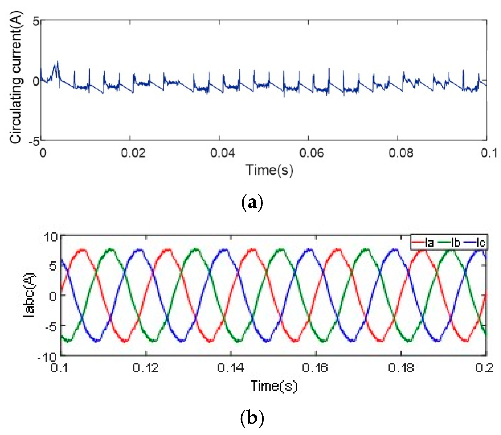
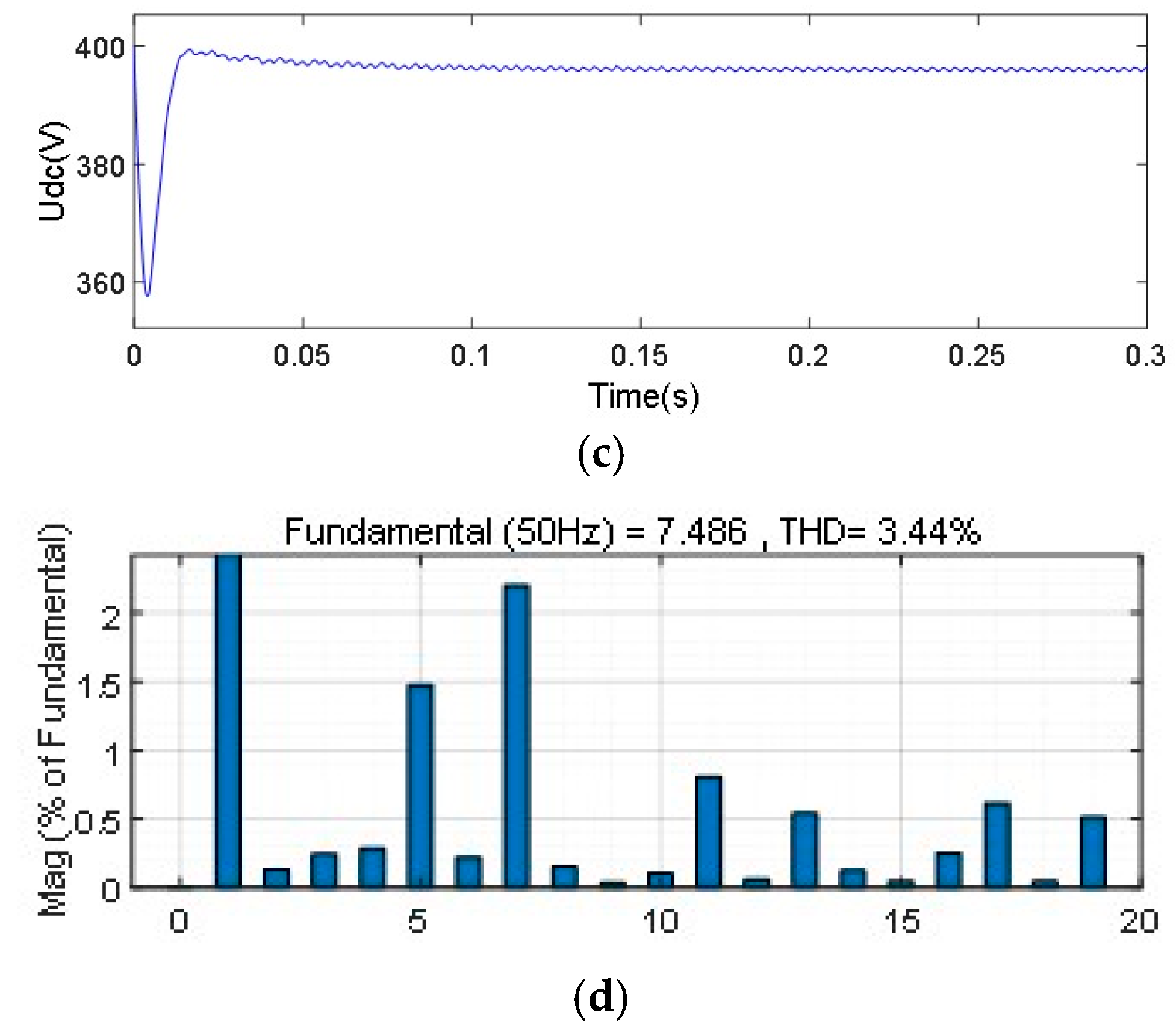
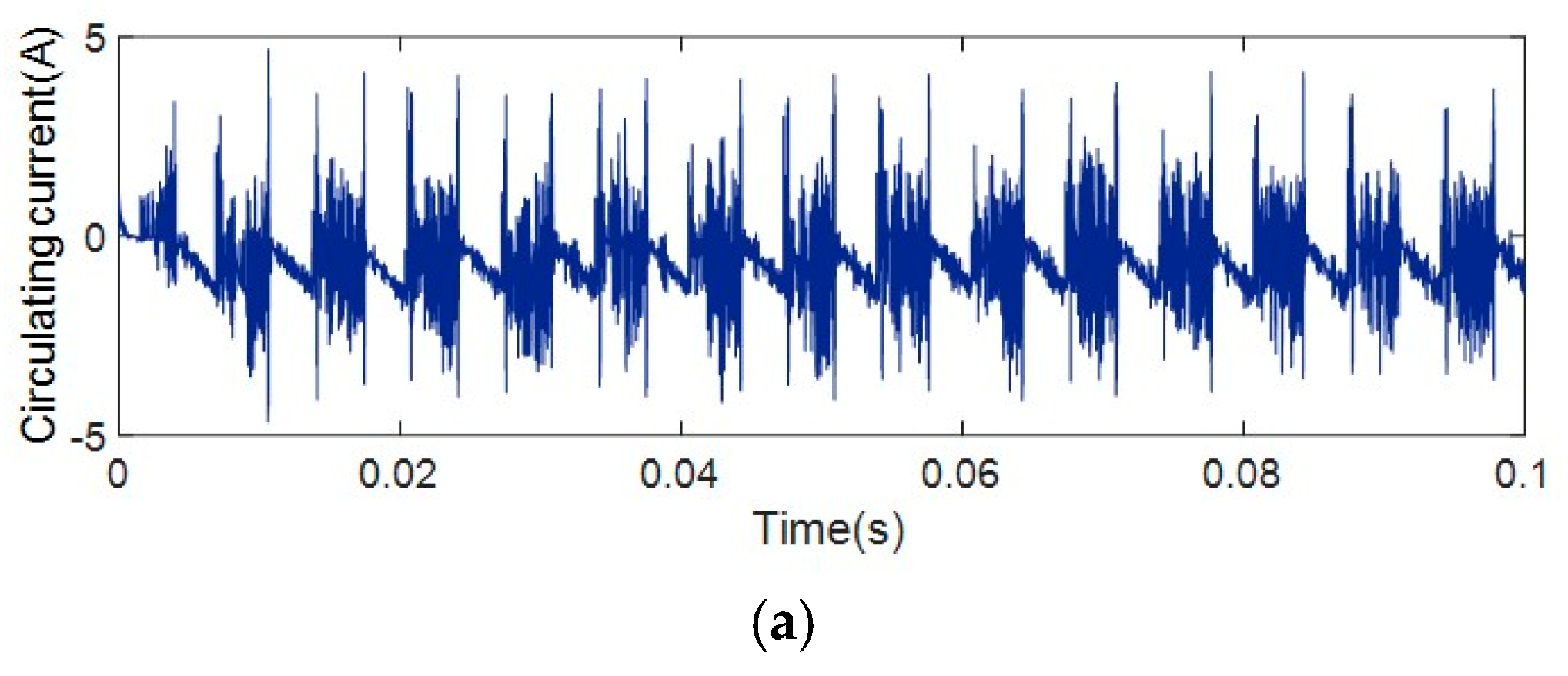
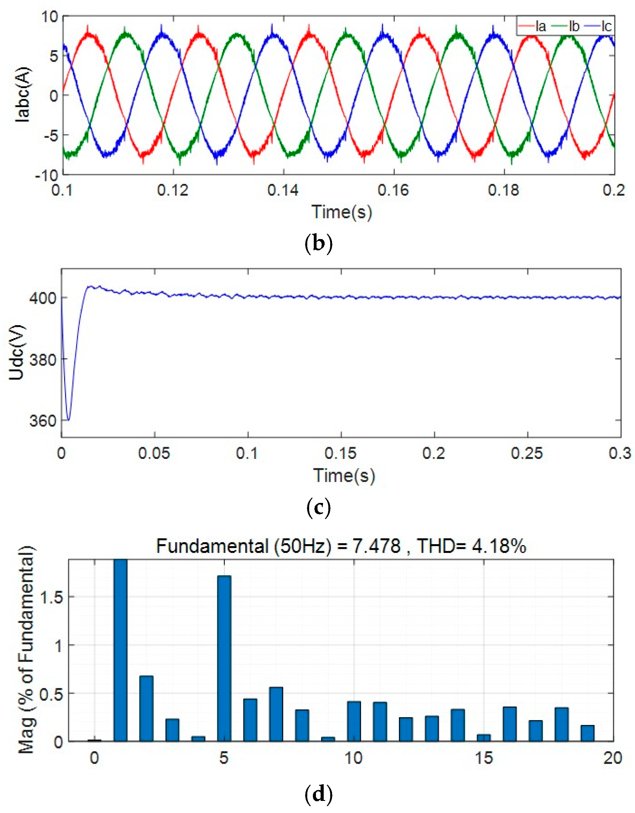
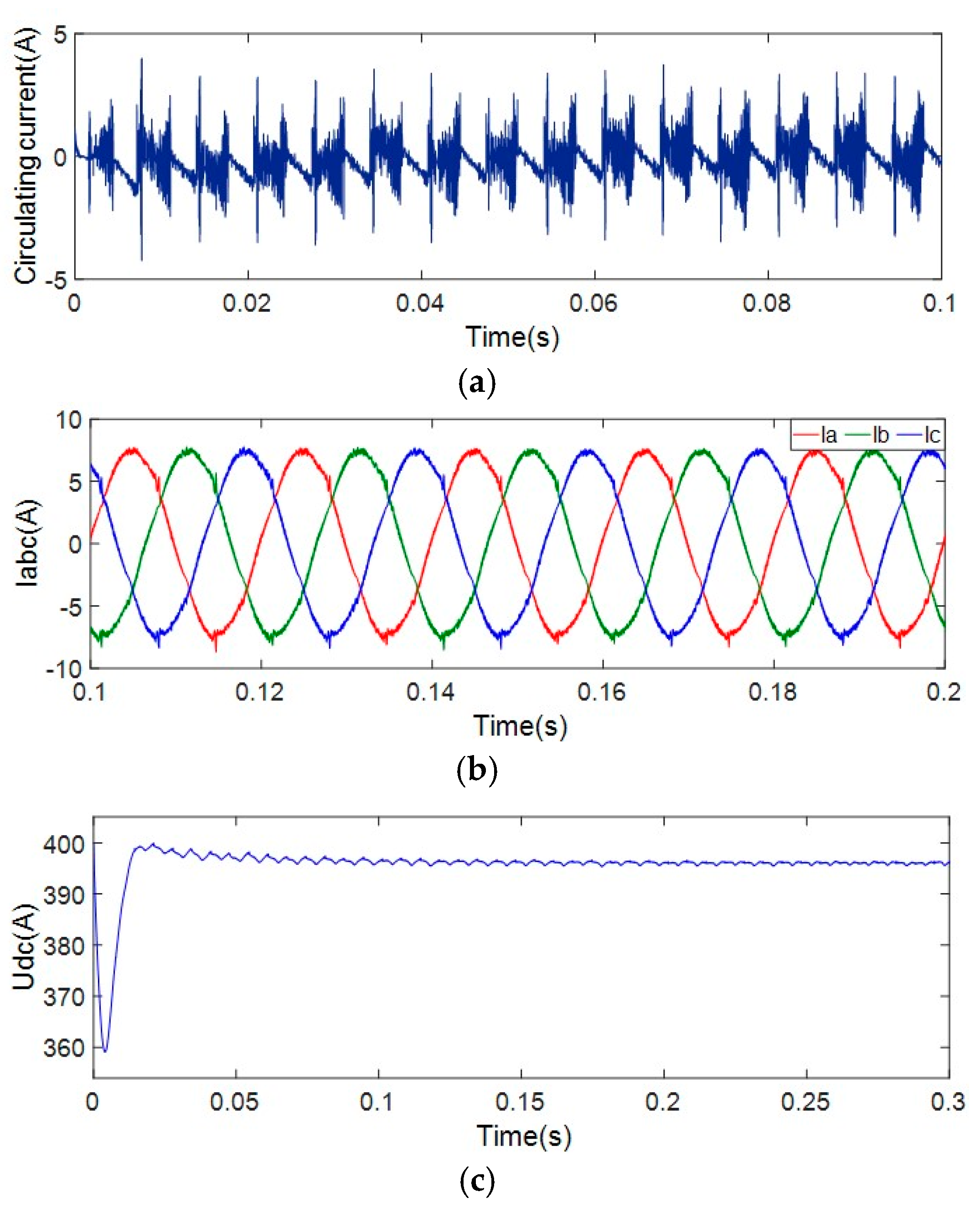
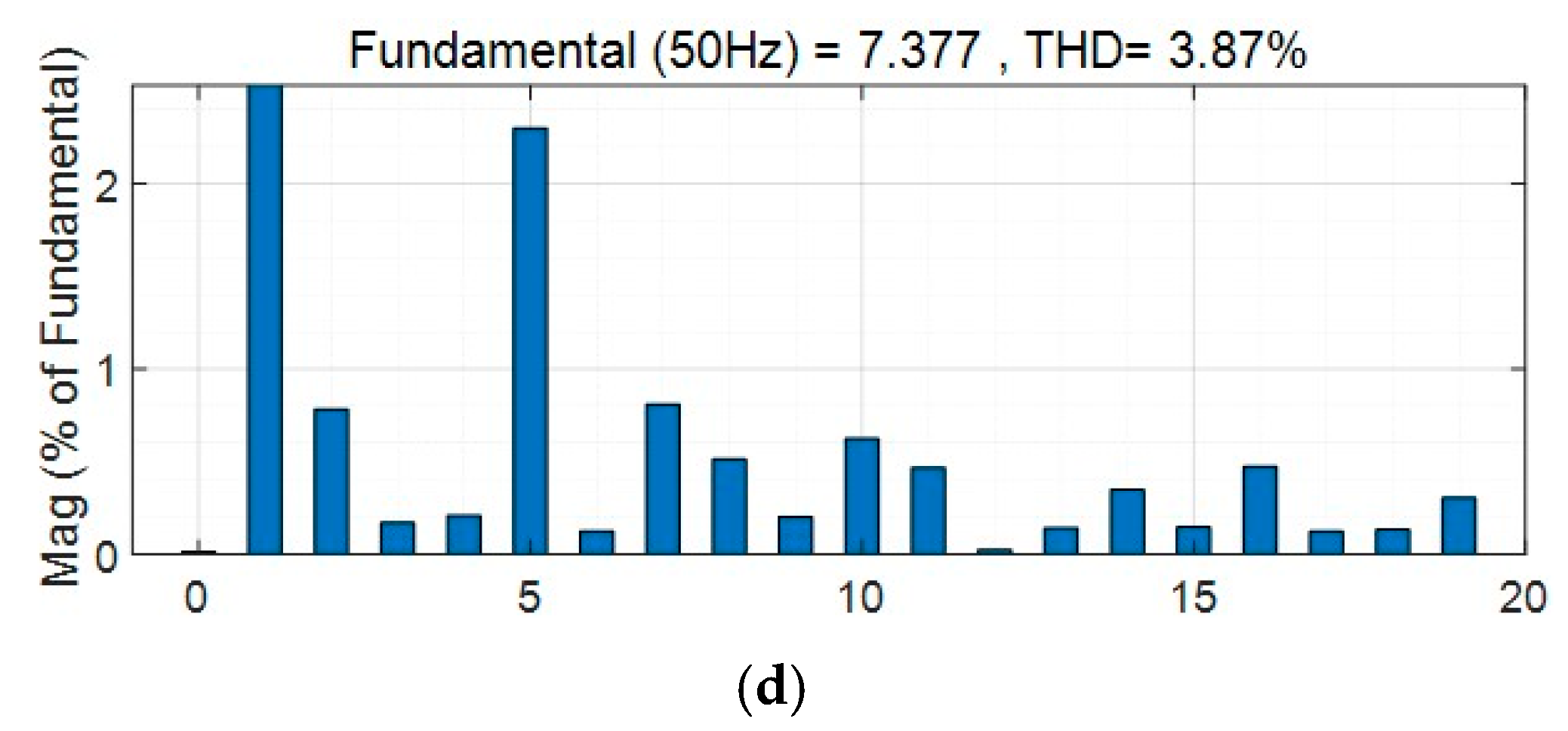
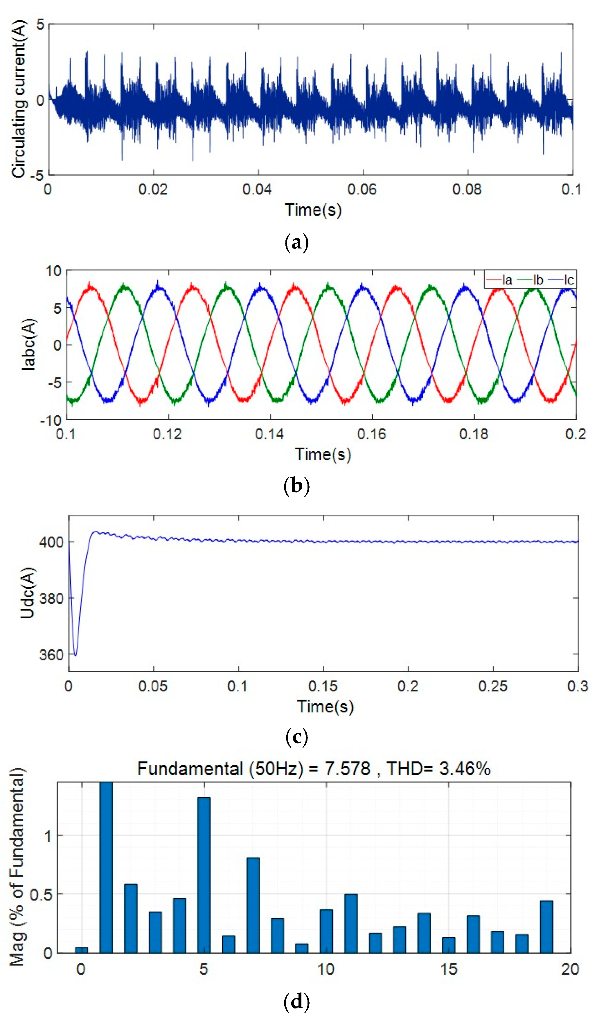
4.1. The DC Side Inductance Parameters of the Parallel Modules Are Different

Next, the simulation analysis is performed for the different inductance parameters of the DC side of the parallel module, and a comparison of the simulation results is given. The DC-side filter inductance of module 1 is 200 μH, and the DC-side inductance of module 2 is 100 μH. The simulation analysis is performed for the scheme with and without the suppression of the circulating current. The simulation results are shown in Figure 9 and Figure 10.
When the shunt converter system does not add the suppression circulating current scheme, the effective value of the positive DC bus circulating current is 1.1 A, and the AC side current THD is 4.63% at this time. The parallel converter system is added with the suppression circulating current scheme. The virtual impedance is set to 20 Ω, and the effective value of the positive DC bus circulating current is 0.6 A. At this time, the AC side current THD is reduced to 3.44%. Due to the addition of droop control on the DC side, the output voltage is lossy, and the output voltage is stable at 395 V.

4.2. The AC Side Inductance Parameters of Parallel Modules Are Different

Different inductance parameters on the AC side of the parallel modules lead to differences in the external characteristics of the parallel modules. According to the parameters shown in Table 1, the simulation analysis is performed on the different conditions of the AC side inductance parameters of the parallel modules. The AC side inductance parameters are set to the AC side of module 1. The side filter inductance is 2.5 mH, and the AC side filter inductance of module 2 is 1 mH.
Figure 11 shows the results of circulating current, output DC voltage, AC side current and AC side current THD of the parallel system without suppressing circulating current control. The effective value of the positive DC bus circulating current is 1.05 A, and the AC side current THD is 4.18% at this time. After adding the control method of suppressing the circulating current, the obtained THD of the circulating current, output DC voltage, AC side current and AC side current of the parallel system is shown in Figure 12. The positive DC bus circulating current is 0.7 A, the output DC voltage is 396 V, and the AC side current is 0.7 A.
The THD was 3.87%. Comparing the results in Figure 11 with the results in Figure 12, after adding the circulating current suppression scheme based on virtual impedance control proposed in this paper, the circulating current of the positive DC bus is reduced to 0.7 A; however, there is still a large peak value. After adding the control scheme to suppress the circulating current, the current THD of the AC side is reduced; however, the output DC voltage is lost due to the addition of droop control on the DC side.
In the case of differences in the filter inductance parameters on the AC side, the simulation results show that the circulating current spikes with the suppression circulating current strategy are almost the same as the circulating current spikes without the circulating current suppression strategy. The reason for this is that, due to the large difference in the inductance of the AC side, the difference in the change value of the inductance voltage is large, which will lead to serious AC side voltage distortion during the commutation process of the converter, which will cause the current of each parallel module to produce peak distortion. The parallel connection of two modules results in the superposition of the current spikes from each module, thus, creating a spike of circulating current.

4.3. Different Positive and Negative DC Bus Inductances for Individual Modules

The positive and negative DC busbars of the parallel converter module are connected in series with a filter inductor. The function is that the symmetry of the four inductors on the DC side can effectively reduce EMI and reduce the harmonic pollution of the parallel converter system to the power grid. Next, we analyze the effect of adding the circulating current suppression scheme to the parallel converter system when the positive and negative DC bus filter inductance parameters of a single current source converter module are different.
The positive DC bus inductance of the three-phase current source converter module is set to 200 μH, and the inductance of the negative DC bus is set to 100 μH. Figure 13 and Figure 14 show the results obtained without adding the suppression loop control scheme and adding the suppression loop control scheme, respectively. When the control scheme of suppressing the circulating current is not added, the effective value of the circulating current is 1.05 A, because the four DC side inductances of the parallel system are asymmetrical, which leads to the increase of the differential mode current of the system, thereby, increasing the circulating current.
After adding the suppression circulating current control scheme, the effective value of the circulating current is reduced to 0.62 A, and the AC side current THD is reduced; however, the circulating current still has a spike problem, which shows that the virtual impedance-based suppression circulating current control scheme in this paper has little influence on the differential mode current. Differential mode current needs to be added on the basis of the scheme in this article to increase the scheme of suppressing differential mode current.
The simulation results show that the circulating current spike after adding the suppression circulating current scheme is larger than that without the control scheme. The reason for the analysis is that the control scheme adopts the DC side droop control method, which is equivalent to connecting the resistance in series on the DC output side to change the external characteristics of the converter module.
Adding droop control increases the difference between the impedances of the positive and negative DC buses of each converter module, resulting in the voltage distortion of each converter module during voltage commutation, which further leads to the distortion of the AC side current of each module. Eventually, the circulating current peak of the parallel system increases; however, adding the control strategy proposed in this paper to suppress the circulating current can effectively reduce the effective value of the circulating current and the THD of the parallel system.

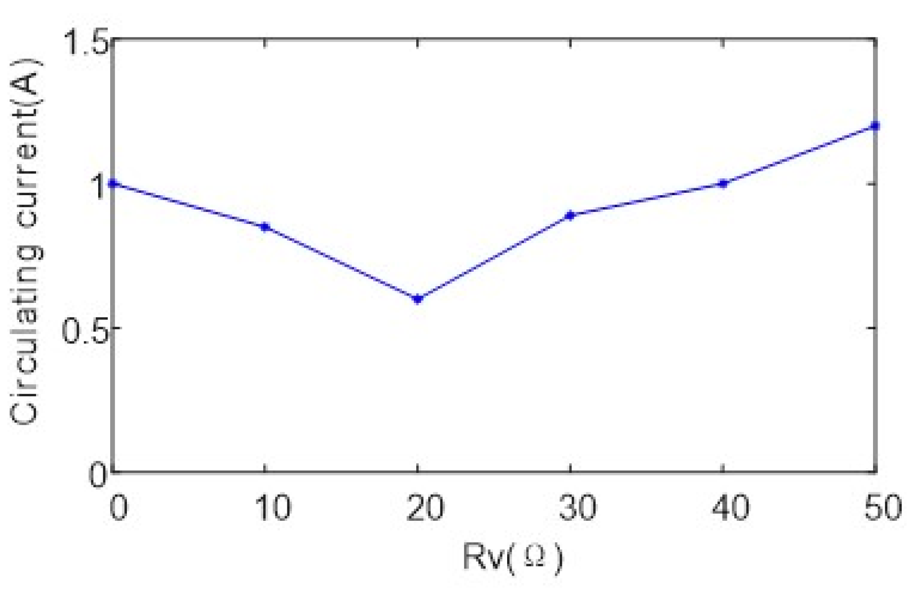
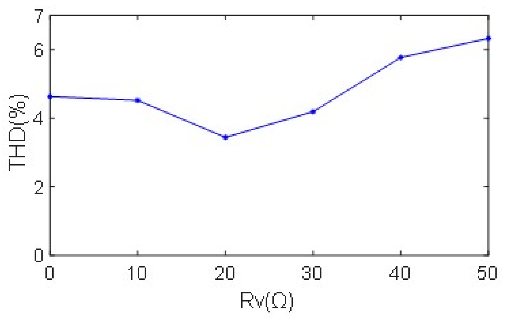
4.4. The Relationship between Virtual Impedance and Circulating Current

In order to verify the effectiveness of the method of suppressing the circulating current proposed in this paper, the simulation of different virtual impedances was conducted, and the relationship between the parallel circulating current and the virtual impedance was obtained, as shown in Figure 15. When the virtual impedance Rv was less than 20 Ω, the circulating current was suppressed. The effect was the best, however, when the virtual impedance was not as large as possible.
When the virtual impedance value gradually increased, the effect of suppressing the circulating current gradually weakened. When the virtual impedance increased to a certain value, the circulating current further increased, which was opposite to the effect of increasing the method of suppressing the circulating current. The reason is that, when the virtual impedance increases to a certain value, the ratio of the voltage across the AC side capacitor of the converter to the actual voltage across the virtual impedance is inconsistent with the set voltage ratio, resulting in a non-proportional feedback amount adjusted by the virtual impedance.
When the virtual impedance is too large, the voltage drop on the virtual impedance increases, and the voltage of the filter inductor on the AC side decreases, resulting in a decrease in the bridge arm voltage input to the three-phase converter, and a large control error will occur. The relationship between the AC side current THD and the virtual impedance is shown in Figure 16. When the virtual impedance is 20 Ω, the AC side current THD is the smallest. As the virtual impedance increases, the AC side current THD increases.

5. Conclusions

In this paper, we classified the schemes of suppressing circulation, which can be divided into centralized control, master–slave control, decentralized control, and wireless control. The advantages and disadvantages of each control scheme were analyzed and compared. The circulating current of the parallel three-phase current source converter was mathematically modeled, the expression of the circulating current was obtained, and the factors that affect the size of the circulating current were obtained through analysis.
According to an in-depth analysis of the existing schemes, we proposed a scheme based on virtual impedance for shunt current source converters to suppress the circulating current. Impedance control and droop control on the DC side were used to realize wireless current sharing control between parallel modules. The scheme was a wireless control scheme that can avoid the use of communication lines between modules, improve the scalability and modularity of the power supply, and greatly improve the redundancy of the parallel system.
In order to verify the effectiveness of the proposed scheme, the control scheme was simulated under the conditions of different circuit parameters of parallel modules and different conditions of positive and negative DC bus inductances of a single module, and the suppression effect of the scheme was analyzed. The simulation results showed that the control strategy proposed in this paper to suppress the circulating current reduced the circulating current to 50% of that without the control scheme and reduced the AC side current THD.
By comparing the relationship between the circulating current and the virtual impedance of parallel converter systems with different virtual impedances, the results showed that the virtual impedance could not be very large. When the THD was high and the virtual impedance was too large, unnecessary power loss occurred, reducing the efficiency of the parallel converter system. The scheme has the advantages of no communication line, simple control, and high reliability.
However, the shunt current source converter based on virtual impedance studied in this paper adopted DC side droop control, which causes output voltage loss. At the same time, the inductance of the DC side of the converter in this paper is small, which leads to the situation that the output DC current fluctuates greatly. However, using a small inductor on the DC side of the converter can effectively reduce the size of the parallel converter system.
In order to realize the high power density of the parallel system, reduce the volume, and apply it to the occasions with high requirements for the converter system, how to reduce the current fluctuation when using a small inductance on the DC side of the converter requires further research. The control strategy proposed in this paper has not been verified by experiments. Therefore, the theoretical part and the simulation part of the control strategy proposed in this paper were comprehensively analyzed to verify the effectiveness of the strategy theoretically and provide theoretical support for future experimental verification.
A future work is to experimentally verify the proposed strategy for suppressing circulation. The experiment will first design and build two three-phase current source converter platforms to verify the rationality of the voltage and current double closed-loop control method and the design of the space vector modulation strategy. Next, the parallel system of two three-phase current source converters can be tested. In the experimental verification, the same AC power supply and DC side load can be used to verify the effectiveness of the control strategy proposed in this paper under different hardware parameters of parallel modules.

Author Contributions

Conceptualization, X.F., H.W. and X.G.; methodology, X.F., H.W., X.G., C.S., D.J., C.C. and J.M.G.; software, X.F., H.W. and X.G.; validation, X.F., H.W., X.G., C.S., D.J., C.C. and J.M.G.; formal analysis, X.F., H.W., X.G., C.S., D.J., C.C. and J.M.G.; investigation, X.F., H.W., X.G., C.S., D.J., C.C. and J.M.G.; resources, X.F., H.W., X.G., C.S., D.J., C.C. and J.M.G.; data curation, X.F., H.W., X.G., C.S., D.J., C.C. and J.M.G.; writing—original draft preparation, X.F.; writing—review and editing, X.F., H.W., X.G., C.S., D.J., C.C. and J.M.G.; visualization, X.F., H.W., X.G., C.S., D.J., C.C. and J.M.G.; supervision, H.W., X.G., C.S., D.J., C.C. and J.M.G.; project administration, X.G., C.S., D.J., C.C. and J.M.G. All authors have read and agreed to the published version of the manuscript.

Funding

This work was supported by the National Key Research and Development Program of China (2021YFB2601600), Hebei Province Natural Science Foundation (F2020203013) and Hebei Province 333 Talent Program (A202005001).

Institutional Review Board Statement

Not applicable.

Informed Consent Statement

Not applicable.

Data Availability Statement

Not applicable.

Conflicts of Interest

The authors declare no conflict of interest.

References

  1. Wei, B.; Vásquez, J.C.; Guerrero, J.M.; Guo, X. Control architecture for paralleled current-source-inverter (CSI) based uninterruptible power systems (UPS). In Proceedings of the 2016 IEEE 8th International Power Electronics and Motion Control Conference (IPEMC-ECCE Asia), Hefei, China, 22–26 May 2016; pp. 151–156. [Google Scholar]
  2. Guo, X. A Novel CH5 Inverter for Single-Phase Transformerless Photovoltaic System Applications. IEEE Trans. Circuits Syst. II: Express Briefs 2017, 64, 1197–1201. [Google Scholar] [CrossRef]
  3. Guo, X. Three-Phase CH7 Inverter with a New Space Vector Modulation to Reduce Leakage Current for Transformerless Photovoltaic Systems. IEEE J. Emerg. Sel. Top. Power Electron. 2017, 5, 708–712. [Google Scholar] [CrossRef]
  4. Wei, Q.; Wu, B.; Xu, D.; Zargari, N.R. A Medium-Frequency Transformer-Based Wind Energy Conversion System Used for Current-Source Converter-Based Offshore Wind Farm. IEEE Trans. Power Electron. 2017, 32, 248–259. [Google Scholar] [CrossRef]
  5. Zhao, S.; Molina, J.M.; Silva, M.; Oliver, J.A.; Alou, P.; Torres, J.; Arevalo, F.; Garcia, O.; Cobos, J.A. Design of Energy Control Method for Three-Phase Buck-Type Converter with Very Demanding Load Steps to Achieve Smooth Input Currents. IEEE Trans. Power Electron. 2016, 31, 3217–3226. [Google Scholar] [CrossRef]
  6. Zhang, Y.; Jahns, T.M. Uncontrolled Generator Operation of PM Synchronous Machine Drive with Current-Source Inverter Using Normally on Switches. IEEE Trans. Ind. Appl. 2017, 53, 203–211. [Google Scholar] [CrossRef]
  7. Zhang, Y.; Yi, Y.; Dong, P.; Liu, F.; Kang, Y. Simplified Model and Control Strategy of Three-Phase PWM Current Source Converters for DC Voltage Power Supply Applications. IEEE J. Emerg. Sel. Top. Power Electron. 2015, 3, 1090–1099. [Google Scholar] [CrossRef]
  8. Wang, F.; Wang, Y.; Gao, Q.; Wang, C.; Liu, Y. A Control Strategy for Suppressing Circulating Currents in Parallel-Connected PMSM Drives with Individual DC Links. IEEE Trans. Power Electron. 2016, 31, 1680–1691. [Google Scholar] [CrossRef]
  9. Vasquez, J.C.; Mastromauro, R.A.; Guerrero, J.M.; Liserre, M. Voltage Support Provided by a Droop-Controlled Multifunctional Inverter. IEEE Trans. Ind. Electron. 2009, 56, 4510–4519. [Google Scholar] [CrossRef]
  10. Shahin, A.; Moussa, H.; Forrisi, I.; Martin, J.-P.; Nahid-Mobarakeh, B.; Pierfederici, S. Reliability Improvement Approach Based on Flatness Control of Parallel-Connected Inverters. IEEE Trans. Power Electron. 2017, 32, 681–692. [Google Scholar] [CrossRef]
  11. Kan, Z.; Zhang, C.; Zhang, B.; Wang, X. Analysis of the conflict between close-loop control and the current-sharing of ac parallel inverters and parallel control strategy. In Proceedings of the IEEE International Power Electronics and Motion Control Conference, Wuhan, China, 17–20 May 2009; pp. 368–372. [Google Scholar]
  12. Zhang, Y.; Yu, M.; Liu, F.; Kang, Y. Instantaneous Current-Sharing Control Strategy for Parallel Operation of UPS Modules Using Virtual Impedance. IEEE Trans. Power Electron. 2013, 28, 432–440. [Google Scholar] [CrossRef]
  13. Praveena, K.; Swarnasri, K. Circulating current harmonics suppression with fuzzy controller in modular multi-level inverter. Mater. Today: Proc. 2021. [Google Scholar] [CrossRef]
  14. Qin, F.; Gao, F.; Wang, X.; Niu, D. Circulating Current Control Method for Nine-Arm Modular Multilevel Converter. In Proceedings of the 2020 IEEE 9th International Power Electronics and Motion Control Conference (IPEMC2020-ECCE Asia), Nanjing, China, 29 November–2 December 2020; pp. 699–703. [Google Scholar]
  15. Wang, J.; Liang, J.; Wang, C.; Dong, X. Circulating current suppression for MMC-HVDC under unbalanced grid conditions. In Proceedings of the 2016 IEEE Industry Applications Society Annual Meeting, Portland, OR, USA, 2–6 October 2016; pp. 1–9. [Google Scholar]
  16. Qiu, J.; Hang, L.; Liu, D.; Geng, S.; Ma, X.; Li, Z. Novel Method for Circulating Current Suppression in MMCs Based on Multiple Quasi-PR Controller. J. Power Electron. 2018, 18, 1659–1669. [Google Scholar]
  17. Uddin, W.; Busarello, T.D.C.; Zeb, K.; Khan, M.A.; Yedluri, A.K.; Kim, H.-J. Control Strategy Based on Arm-Level Control for Output and Circulating Current of MMC in Stationary Reference Frame. Energies 2021, 14, 4160. [Google Scholar] [CrossRef]
  18. Zhang, M.; Shen, Y.; Sun, H.; Guo, R. MMC-HVDC circulating current suppression method based on improved proportional resonance control. Energy Rep. 2020, 6, 863–871. [Google Scholar] [CrossRef]
  19. Far, A.; Jovcic, D. Circulating current suppression control dynamics and impact on MMC converter dynamics. In Proceedings of the 2015 IEEE Eindhoven PowerTech, Eindhoven, The Netherlands, 29 June–2 July 2015; IEEE: New Jersey, NJ, USA, 2016. [Google Scholar]
  20. Guila-León, J.; Chias-Palacios, C.D.; Vargas-Salgado, C.; Hurtado-Perez, E.; García, E. Optimal PID Parameters Tunning for a DC-DC Boost Converter: A Performance Comparative Using Grey Wolf Optimizer, Particle Swarm Optimization and Genetic Algorithms. In Proceedings of the 7th IEEE Conference on Technologies for Sustainability IIESusTech, Santa Ana, CA USA, 23–25 April 2020. [Google Scholar]
  21. Bakar, A.A.; Pathan, E.; Khan, M.K.; Sadiq, M.A.; Shaikh, M.A. Decentralized Virtual Impedance-based Circulating Current Suppression Control for Islanded Microgrids. Eng. Technol. Appl. Sci. Res. 2021, 11, 6734–6739. [Google Scholar] [CrossRef]
  22. Wen, C.; Zhang, Z.; Chen, T.; Lin, H.; Liu, H. Investigation of GIS enclosure circulating current in UHV substation with hybrid reactive power compensation. Electr. Power Syst. Res. 2022, 203, 107666. [Google Scholar] [CrossRef]
  23. Cai, J.; Chen, C.; Duan, S.; Yang, D. Centralized control of large capacity parallel connected power conditioning system for battery energy storage system in microgrid. In Proceedings of the 2014 IEEE Energy Conversion Congress and Exposition (ECCE), Pittsburgh, PA, USA, 15–18 September 2014; pp. 409–413. [Google Scholar]
  24. Xing, X.; Zhang, Z.; Zhang, C.; He, J.; Chen, A. Space Vector Modulation for Circulating Current Suppression Using Deadbeat Control Strategy in Parallel Three-Level Neutral-Clamped Inverters. IEEE Trans. Ind. Electron. 2017, 64, 977–987. [Google Scholar] [CrossRef]
  25. Rahmani, S.; Saeidi, M.; Pirayesh, A. A combinational power sharing strategy based on master-slave and droop methods for power-electronics-interfaced distributed generation units operating in a DC micro-grid. In Proceedings of the 2017 IEEE International Conference on Smart Energy Grid Engineering (SEGE), Oshawa, ON, USA, 14–17 August 2017; pp. 1–6. [Google Scholar]
  26. Jung, H.; Sul, S. A design of circulating current controller for paralleled inverter with non-isolated dc-link. In Proceedings of the 2017 IEEE 3rd International Future Energy Electronics Conference and ECCE Asia (IFEEC 2017—ECCE Asia), Kaohsiung, Taiwan, 4–7 June 2017; pp. 1913–1919. [Google Scholar]
  27. Cheng, C.; Zeng, Z.; Yang, H.; Zhao, R. Wireless parallel control of three-phase inverters based on virtual synchronous generator theory. In Proceedings of the 2013 International Conference on Electrical Machines and Systems (ICEMS), Busan, Korea, 26–29 October 2013; pp. 162–166. [Google Scholar]
  28. Guan, Y.; Guerrero, J.M.; Zhao, X.; Vasquez, J.C.; Guo, X. A New Way of Controlling Parallel-Connected Inverters by Using Synchronous-Reference-Frame Virtual Impedance Loop—Part I: Control Principle. IEEE Trans. Power Electron. 2016, 31, 4576–4593. [Google Scholar] [CrossRef] [Green Version]
  29. Sun, B.; Liu, H.; Wu, H.; Wang, W. A suppression method of circulating current in parallel photovoltaic system based on virtual impedance. In Proceedings of the 2016 IEEE 8th International Power Electronics and Motion Control Conference (IPEMC-ECCE Asia), Hefei, China, 22–26 May 2016; pp. 1532–1538. [Google Scholar]
  30. Shi, R.; Zhang, X.; Hu, C.; Gu, J.; Xu, H.; Yu, Y.; Ni, H. Virtual impedance design for virtual synchronous generator controlled parallel microgrid inverters based on a cascaded second order general integrator scheme. In Proceedings of the 2016 IEEE PES Asia-Pacific Power and Energy Engineering Conference (APPEEC), Xi’an, China, 25–28 October 2016; pp. 815–819. [Google Scholar]
  31. Chen, Y.; Guo, H.; Ma, H.; Zhou, Y. Circulating current minimisation of paralleled 400 Hz three-phase four-leg inverter based on third harmonics injection. J. Eng. 2018, 13, 512–519. [Google Scholar] [CrossRef]
  32. Raj, D.C.; Gaonkar, D.N. Frequency and voltage droop control of parallel inverters in microgrid. In Proceedings of the 2016 2nd International Conference on Control, Instrumentation, Energy & Communication (CIEC), Kolkata, India, 28–30 January 2016; pp. 407–411. [Google Scholar]
  33. Yang, S.; Cao, P.; Chang, L.; Xie, Z.; Zhang, X. Droop control based stabilizing method for V/f PWM inverter fed induction motor drive system. In Proceedings of the IEEE Canadian Conference on Electrical and Computer Engineering, Halifax, NS, Canada, 3–6 May 2015; pp. 1078–1082. [Google Scholar]
  34. Altahir, S.Y.; Yan, X.; Liu, X. A poer sharing method for inverters in microgrid based on the virtual power and virtual impedance control. In Proceedings of the 2017 11th IEEE International Conference on Compatibility, Power Electronics and Power Engineering (CPE-POWERENG), Cadiz, Spain, 4–6 April 2017; pp. 151–156. [Google Scholar]
  35. Wang, S.; Liu, Z.; Liu, J.; An, R.; Xin, M. Breaking the Boundary: A Droop and Master-Slave Hybrid Control Strategy for Parallel Inverters in Islanded Microgrids. In Proceedings of the 2017 IEEE Energy Conversion Congress and Exposition (ECCE), Cincinnati, OH, USA, 1–5 October 2017; pp. 3345–3352. [Google Scholar]
  36. Wei, B.; Guerrero, J.M.; Vásquez, J.C.; Guo, X. A circulating current suppression method for parallel connected voltage-source-inverters (VSI) with common DC and AC buses. In Proceedings of the 2016 IEEE Energy Conversion Congress and Exposition (ECCE), Milwaukee, WI, USA, 18–22 September 2016; pp. 1–6. [Google Scholar]
  37. Deshmukh, R.R.; Ballal, M.S.; Suryawanshi, H.M. A Fuzzy Logic Based Supervisory Control for Power Management in Multibus DC Microgrid. IEEE Trans. Ind. Appl. 2020, 56, 6174–6185. [Google Scholar] [CrossRef]
  38. Guo, B.; Wang, F.; Aeloiza, E. A novel three-phase current source converter with delta-type input connection to reduce the device conduction loss. IEEE Trans. Power Electron. 2016, 31, 1074–1084. [Google Scholar] [CrossRef]
  39. Colombi, S.; Balblano, C. Clean Input UPS with Fast Converter Control and Improved Battery Life. U.S. Patent US7768805, 10 September 2008. [Google Scholar]
  40. Chae, B.; Kang, T.; Kang, T.; Suh, Y. Carrier based PWM for three-phase three-switch buck-type rectifier in EV rapid charging system. In Proceedings of the 2015 9th International Conference on Power Electronics and ECCE Asia (ICPE-ECCE Asia), Seoul, Korea, 1–5 June 2015; pp. 881–889. [Google Scholar]
  41. Tan, L.; Li, Y.; Wang, P.; Liu, C.; Li, Z.; Chen, Y.; Xu, W. A novel control method for IGBT current source converter. In Proceedings of the 2008 13th International Power Electronics and Motion Control Conference 2008, Poznan, Poland, 1–3 September 2008; pp. 405–408. [Google Scholar]
  42. Suhara, E.M.; Nandakumar, M. Analysis of hysteresis current control techniques for three phase PWM rectifiers. In Proceedings of the 2015 IEEE International Conference on Signal Processing, Informatics, Communication and Energy Systems (SPICES), Kozhikode, India, 19–21 February 2015; pp. 1–5. [Google Scholar]
  43. Bai, Z.; Ma, H.; Xu, D.; Wu, B.; Fang, Y.; Yao, Y. Resonance Damping and Harmonic Suppression for Grid-Connected Current-Source Converter. IEEE Trans. Ind. Electron. 2014, 61, 3146–3154. [Google Scholar] [CrossRef]
  44. Meng, L.; Guerrero, J.M. Optimization for Customized Power Quality Service in Multibus Microgrids. IEEE Trans. Ind. Electron. 2017, 64, 8767–8777. [Google Scholar] [CrossRef]
  45. Guedouani, R.; Fiala, B.; Berkouk, E.M.; Boucherit, M.S. Modeling and control of multilevel three-phase PWM current source inverter. In Proceedings of the International Aegean Conference on Electrical Machines and Power Electronics and Electromotion, Joint Conference, Istanbul, Turkey, 8–10 September 2011; pp. 455–460. [Google Scholar]
  46. Liu, F.; Wu, B.; Zargari, N.R.; Pande, M. An Active Damping Method Using Inductor-Current Feedback Control for High-Power PWM Current-Source Converter. IEEE Trans. Power Electron. 2011, 26, 2580–2587. [Google Scholar] [CrossRef]
  47. Shi, Y.; Su, J. An active damping method based on PR control for LCL-filter-based grid-connected inverters. In Proceedings of the 2014 17th International Conference on Electrical Machines and Systems (ICEMS), Hangzhou, China, 22–25 October 2014; pp. 944–948. [Google Scholar]
  48. Bai, Z.; Li, C.; Xu, D. A zero-current switching (ZCS) current source converter for high-frequency PWM applications. In Proceedings of the IECON 201—42nd Annual Conference of the IEEE Industrial Electronics Society 2016, Florence, Italy, 24–27 October 2016; pp. 3213–3216. [Google Scholar]
  49. Elgenedy, M.A.; Elserougi, A.A.; Abdel-Khalik, A.S.; Massoud, A.M.; Ahmed, S. A Space Vector PWM Scheme for Five-Phase Current-Source Converters. IEEE Trans. Ind. Electron. 2016, 63, 562–573. [Google Scholar] [CrossRef]
  50. Wei, Q.; Xing, L.; Xu, D.; Wu, B.; Zargari, N.R. Modulation Schemes for Medium-Voltage PWM Current Source Converter-Based Drives: An Overview. IEEE J. Emerg. Sel. Top. Power Electron. 2019, 7, 1152–1161. [Google Scholar] [CrossRef]
Figure 1. Topology of three-phase current source converter.
Energies 15 01952 g001
Figure 2. Double closed-loop control block diagram.
Energies 15 01952 g002
Figure 3. Space vector sector distribution.
Energies 15 01952 g003
Figure 4. Topology of two current source converters in parallel.
Energies 15 01952 g004
Figure 5. DC equivalent circuit.
Energies 15 01952 g005
Figure 6. DC equivalent circuit, figures (af) show six circulation paths respectively.
Energies 15 01952 g006
Figure 7. Circulating current suppression method of paralleled current source converters.
Energies 15 01952 g007
Figure 8. AC equivalent circuit.
Energies 15 01952 g008
Figure 9. The control scheme for suppressing circulating current is not added under different DC-side inductance parameters (a) Positive DC bus circulating current. (b) AC side current. (c) DC side output voltage. (d) THD of AC side current.
Energies 15 01952 g009
Figure 10. Adding a control scheme of suppressing circulating current under different conditions of DC-side inductance parameters (a) Positive DC bus circulating current. (b) AC side current. (c) DC side output voltage. (d) THD of AC side current.
Energies 15 01952 g010aEnergies 15 01952 g010b
Figure 11. In the case of different AC side inductance parameters, no circulating current suppression control scheme is added (a) Positive DC bus circulating current. (b) AC side current. (c) DC side output voltage. (d) THD of AC side current.
Energies 15 01952 g011aEnergies 15 01952 g011b
Figure 12. Adding a control scheme for suppressing circulating current when the inductance parameters of the AC side are different (a) Positive DC bus circulating current. (b) AC side current. (c) DC side output voltage. (d) THD of AC side current.
Energies 15 01952 g012aEnergies 15 01952 g012b
Figure 13. The control scheme of the suppressing circulating current is not added under different conditions of positive and negative DC bus inductance of parallel modules (a) Positive DC bus circulating current. (b) AC side current. (c) DC side output voltage. (d) THD of AC side current.
Energies 15 01952 g013
Figure 14. The control scheme of suppressing circulating current is added under different conditions of the positive and negative DC bus inductance of the parallel module (a) Positive DC bus circulating current. (b) AC side current. (c) DC side output voltage. (d) THD of AC side current.
Energies 15 01952 g014aEnergies 15 01952 g014b
Figure 15. Relationship between circulating current and virtual impedance.
Energies 15 01952 g015
Figure 16. Relationship between THD and virtual impedance.
Energies 15 01952 g016
Table 1. Simulation parameters for parallel modules.
Simulation ParametersNumerical ValueSimulation ParametersNumerical Value
Grid voltage amplitude/frequency380 V/50 HzLoad Resistance50 Ω
DC bus voltageUDC = 400 VOperating frequencyfs = 40 kHz
DC side filter capacitorCDC = 940 μFAC side filter inductorL = 2.5 mH
DC side filter inductor of module 1LDC1 = 200 μHAC side filter capacitorC = 9.4 μF
DC side filter inductor of module 2LDC2 = 100 μHVirtual impedanceRv = 20 Ω
Publisher’s Note: MDPI stays neutral with regard to jurisdictional claims in published maps and institutional affiliations.

