Article

Thermoelectric Performance Evaluation and Optimization in a Concentric Annular Thermoelectric Generator under Different Cooling Methods

1
School of Automation, Wuhan University of Technology, Wuhan 430070, China
2
Hubei Key Laboratory of Advanced Technology for Automotive Components, Wuhan University of Technology, Wuhan 430070, China
*
Authors to whom correspondence should be addressed.
Submission received: 19 February 2022 / Revised: 14 March 2022 / Accepted: 16 March 2022 / Published: 18 March 2022
(This article belongs to the Special Issue Advanced Studies of Thermoelectric Systems)

Abstract

:
To ensure effective heat recovery of thermoelectric generators, a cooling system is necessary to maintain the working temperature difference of the thermoelectric couples, which decreases continuously due to thermal diffusion. In order to evaluate and improve the thermoelectric performance of a concentric annular thermoelectric generator under various cooling methods, a comprehensive numerical model of the thermo-fluid-electric multi-physics field for an annular thermoelectric generator with a concentric annular heat exchanger was developed using the finite-element method. The effects of four cooling methods and different exhaust parameters on the thermoelectric performance were investigated. The results show that, in comparison to the cocurrent cooling pattern, the countercurrent cooling pattern effectively reduces temperature distribution non-uniformity and hence increases the maximum output power; however, it requires more thermoelectric semiconductor materials. Furthermore, when using the cocurrent air-cooling method, high exhaust temperatures may result in lower output power; high exhaust mass flow rates result in high exhaust resistance and reduce system net power. The maximum net power output Pnet = 432.42 W was obtained using the countercurrent water-cooling, corresponding to an optimal thermoelectric semiconductor volume of 9.06 × 10⁻⁴ m3; when compared to cocurrent water-cooling, the maximum net power increased by 8.9%, but the optimal thermoelectric semiconductor volume increased by 21.4%.

1. Introduction

The use of waste heat to generate electricity power via thermoelectric generators has been a focus of attention in the field of energy recycling for many years. The majority of the energy produced by fossil fuels is wasted as heat in internal combustion engine vehicles, with only about 30% of the energy converted to usable work. Thermoelectric generators (TEGs) are believed to have the potential and possibility of being used in an automobile’s thermal energy recovery system due to their unique advantages, such as no moving parts, no pollution, and the ability to immediately convert thermal energy into electric energy [1,2]. TEG can not only reduce pollution, but also improve fuel efficiency and save energy. The primary components of a thermoelectric generator are a thermoelectric module (TEM), a heat exchanger, and a cooling system. A conventional TEM is a thermoelectric device composed of many rectangular shaped p- and n-type thermoelectric semiconductors electrically connected in series via copper sheets and covered with two ceramic plates. The large amount of high-temperature exhaust gas generated in the exhaust should be cooled in time to ensure normal operation. In addition to the field of automobile exhaust gas recovery, TEGs can also be used effectively in fuel cell systems to recover waste heat and improve overall energy conversion efficiency. Musharavati et al. proposed an integrated system that combines a proton exchange membrane fuel cell with a solar pond system and uses TEG to recover thermal energy, thereby addressing the issues of low thermal efficiency and energy output [3]. Subsequently, they proposed a tandem energy recovery system for proton exchange membrane fuel cells, which uses an organic Rankine cycle and thermoelectric power generation technologies for more energy recovery [4].
However, the current TEGs for waste heat recovery system still suffer from low conversion efficiency, which hinders its commercialization. To improve the performance of TEG, the researchers opened up two main research directions. The first is to enhance the thermoelectric efficiency of thermoelectric semiconductor materials, and the second is to optimize the internal structure of TEG.
The dimensionless constant (ZT) is a common metric for evaluating the efficiency and performance of thermoelectric materials. In order to improve the ZT value of thermoelectric semiconductor materials, significant progress has been made by employing modern synthesis and characterization techniques [5,6,7], but most thermoelectric materials now still have ZT values in the range of 1–1.6. Bell pointed out that if ZT values of 2 or greater could be achieved, thermoelectric electronic components would be more widely used [8]. Yin et al. achieved a high ZT of 2.2 at 450 °C by alloying CuBiSe2 into GeTe [9]. Ao et al. assembled a thermoelectric sensor by integrating the n-type Bi2Te3 flexible thin films with p-type Sb2Te3 counterparts and found that the thermal diffusion method is an effective way to fabricate high-performance, flexible Te-embedded Bi2Te3-based thin films [10]. With advancements in thermoelectric materials, thermoelectric power generation technology based on thermoelectric devices is expected to emerge as a new alternative energy technology.
There are several methods to improve the internal structure of a thermoelectric generator, such as optimizing the shape of the thermoelectric semiconductor, improving the thermal management scheme on the hot side of the TEM, and optimizing the TEG cooling system [11]. A pair of thermoelectric couples (TEC), the most fundamental constituent of a thermoelectric module, is often analyzed and optimized by researchers. The energy conversion efficiency and output performance of TEGs are affected by the length of the thermocouple legs, cross-sectional area, and spacing between the legs [12,13]. Chen et al. optimized the geometry of the TEC using a multi-objective genetic algorithm; the optimized output power and efficiency increased by about 51.9% and 5%, respectively [14]. Fan et al. investigated the effects of thermoelectric semiconductor leg cross-sectional area and length on power output, efficiency, and power density of the TEG under various thermal boundary conditions; they determined the optimal cross-sectional area ratio and length of thermocouple with the objective of maximizing peak output power [15]. To accommodate cylindrical heat sources, researchers proposed a new structure of annular thermoelectric couples (ATECs)—a number of ATECs were integrated and assembled into an annular thermoelectric generator (ATEG). The application of ATEG can effectively reduce the contact thermal resistance caused by a geometric mismatch between the cylindrical heat source and the flat-type TEG [16]. Zhu et al. studied the effect of ATEC geometric parameters on ATEG output power and efficiency in three application scenarios, determining the optimal shape factor under various boundary conditions [17]. Weng et al. investigated and improved variable angle ATEC geometry parameters, as well as designed a variable angle thermoelectric generator to increase output performance by 35% [18]. Furthermore, segmented ATEC was proposed [19,20,21], which effectively improved the thermoelectric performance of ATEG by taking the optimal operating temperature range of different thermoelectric materials into account.
Furthermore, improving the heat transfer performance between the hot fluid and hot end of TEG can significantly improve the overall performance of the thermoelectric system. Luo et al. designed a converging TEG with the hot side wall of the heat exchanger slanted inward, effectively increasing power output [22]. Li et al. placed foam metal with 20 pores per inch and a filling rate of 75% in a hot-side heat exchanger—the convective heat transfer coefficient of the channel was improved by a factor of four and the output power was doubled [23]. Yang et al. developed an ATEG based on a concentric annular heat exchanger for a cylindrical channel of an automotive exhaust pipe [24], which significantly improved the heat transfer coefficient and system net power.
The main cooling methods for thermoelectric devices in terms of waste heat dissipation at the cold end of TEG are heat sink heat dissipation [25,26], phase change material heat dissipation [27], air-cooling, and water-cooling [28,29,30]. Water-cooling and air-cooling methods, in particular, are widely used in TEG because of their superior cooling performance, as well as the advantages of a simple structure and broad applicability [31]. For example, He et al. proposed an optimized method to improve a flat plate TEG with ambient air-cooling [32]. Following that, He et al. studied the effect of different cooling methods on optimal TEG performance based on a common flat plate type TEG and found that the reverse flow of heat source and cooling fluid could achieve higher power output [33]. Luo et al. proposed a numerical model of an automotive TEG that used a flat-type tank as the cooling device and internally circulated water as the coolant to evaluate the TEG performance at different vehicle speeds [34].
The cooling methods of ATEG, however, have not been fully evaluated, although a series of investigations have been conducted on ATEG and its performance advantages over the flat type TEG demonstrated. Meanwhile, in practical applications, the exhaust temperature and exhaust mass flow rate vary with vehicle speed, resulting in changes in TEG temperature distribution and exhaust resistance. However, most studies concentrate solely on improving the performance of automotive TEG systems under constant operating conditions, ignoring the effects of vehicle speed and power loss due to exhaust resistance. Furthermore, the vast majority of the literature is based on conventional flat plate-type TEGs, and the applicability of these results and design guidelines to such ATEGs has not yet been verified, especially for the cooling method of ATEGs with a new concentric annular heat exchanger.
Thus, in this paper, a comprehensive numerical model of a thermo-fluid-electric multi-physics field for an ATEG with a concentric annular heat exchanger was developed. Temperature dependence of the physical properties of thermoelectric materials, heat transfer characteristics, effect of heat source parameters on exhaust resistance, and temperature gradient characteristics within the thermoelectric generator were considered. The effects of different heat source parameters on the heat transfer coefficient in the channel and the effects of different cooling methods on the optimal output power, net power, and energy conversion efficiency of this new TEG under different vehicle operating conditions were investigated. The new features of the ATEG thermal energy recovery system were also explored. The research findings may open up new avenues for the use of automotive exhaust heat recovery systems.

2. Mathematical Modeling of the CATEG

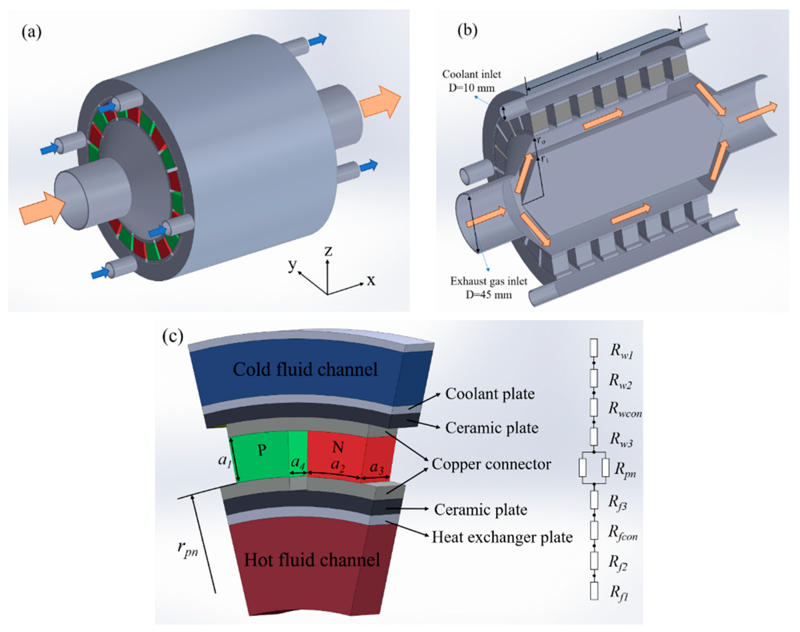
2.1. Three-dimensional Geometry of the CATEG

Figure 1a depicts a 3D schematic view of a water-cooling CATEG. The hot fluid inlet and outlet of the TEG are 45 mm in diameter, which matches the diameter of most automobile exhaust pipes. The ATEC are evenly distributed between the hot end heat exchanger and the radiator via an electrical series and thermal parallel connection. Figure 1b shows the axial profile of the CATEG. The concentric annular heat exchanger has a solid inner tube, and the automotive exhaust flows into the device at a temperature of Tfin and then flows through a narrow channel of the heat exchanger to heat the thermocouple, which then exits through the end of the heat exchanger. The proposed concentric annular heat exchanger compresses the fluid passages and improves heat transfer from the thermal fluid to the thermocouple, thereby improving the TEG output characteristics [24]. In the figure, L represents the length of TEG, while the inner and outer radiuses of the heat exchanger are represented by ri and ro, respectively, with ri = 30 mm and ro = 37 mm. Cooling water flows in at a temperature of Twin from inlets of the heat sink, effectively maintaining the temperature of the TEC cold end, and then flows out from the outlet at the other end. A portion of energy of the exhaust gas is transferred to the hot end as heat, which is directly converted to electrical energy by Seebeck effect of the thermoelectric elements, and the remainder is transferred to the cold end or to the outflow device.
Figure 1c shows the general structure of an annular thermoelectric couple branch and its equivalent thermal resistance. An annular thermoelectric couple is made up of an annular p-type thermoelectric semiconductor leg and an annular n-type thermoelectric semiconductor leg. Each PN leg is connected with a copper piece and the ATEC is insulated on the outside by two curved ceramic pieces (Al2O3). The thermocouple is made of commercially available Bi2Te3 material, which has variable resistivity, thermal conductivity, and Seebeck coefficient dependent on operating temperature. In the figure, a1, a2, and a3 represent the height, inner arc length, and thickness of the ATEC, respectively, and a4 represents the distance between the semiconductor legs. The inner radius of the PN leg is represented by rpn; the thicknesses of ceramic sheets and copper sheets on both sides of the PN leg are denoted by δcer and δcu, respectively; and the wall thicknesses of the heat exchanger is denoted by δplate. Detailed parameters and material properties of the CATEG are shown in Table 1.

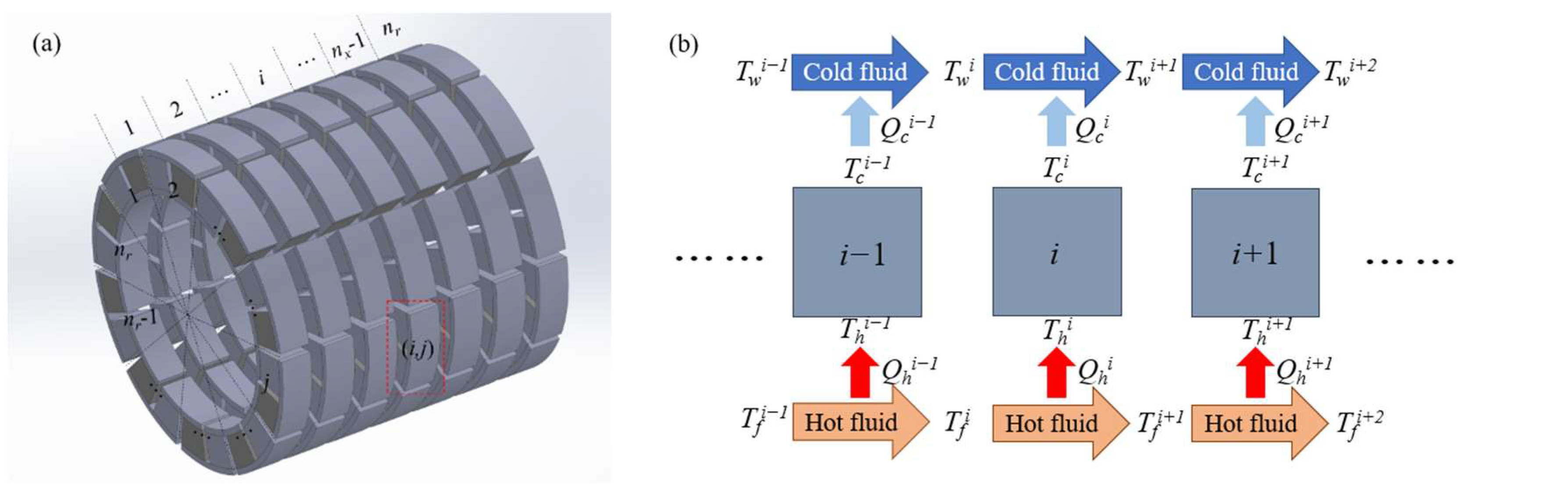
2.2. Main Equations of the Numerical Model

The ATEG non-isothermal finite element model is shown in Figure 2a. It can be divided into nx × nr pairs of thermocouples within the ATEG, with each pair of thermocouples acting as a computational unit. The i-th ring in the x-direction and the j-th thermocouple in the r-direction are chosen as an example, denoted as the (i, j)th computational unit, to illustrate the heat transfer process in this finite element model, where i ranges from 1 to nx and j ranges from 1 to nr. Following that, the CATEG modeling process was illustrated by using the example of cold and hot fluids flowing in the same direction, with the counterflow modeling process being similar to the cocurrent flow. Thermocouples installed in the same ring are connected in series, and ATECs in the same ring are assumed to have the same temperature distribution, thermodynamic properties, and power output; thus, the superscript i can be used to denote the inclusion of nr pairs of ATECs. The numerical calculation is performed with each ring as a new calculation unit. The fluid temperature and ATEC surface temperature in the i-th ring are shown in Figure 2b. The automobile exhaust flows into the ATEG at temperature Tfin and the cold fluid flows into the device at temperature Twin. The hot fluid flows into the i-th ring at temperature Tfi, and its heat is transferred to the ATEC hot end and ring i + 1, respectively, to raise the hot end temperature of the thermocouple to Thi. The hot fluid flows out of ring i at temperature Tfi+1. Similarly, the cold fluid flows into the i-th ring at temperature Twi and its heat is transferred to the ATEC cold end and the i + 1th ring, respectively, cooling the ATEC cold end to Tci and then flowing out of the i-th ring at temperature Twi+1. The precondition in this model is that there should be no air in the thermoelectric semiconductors, and the Thomson effect and thermal radiation could be ignored.
Three sets of heat transmission equations can be used to describe the heat transfer rate at the hot side of the ATEG, Qh, and the heat transfer rate at the cold side, Qc [35]. The first group is represented by the components of the Peltier effect, conduction heat, and Joule heat transfer to both ends of the TEC, respectively; the second group is constructed by considering the rate of heat transfer to the fluid; and the third group is the heat transferred by convection to the fluid at the hot and cold sides of the solid phase given by the cooling Newton law, respectively.
Based on the non-isothermal finite element model and steady-state heat transfer process in a single ring, the two heat transmission components Qhi and Qci are described as:
{ Q h i = n r [ α p n i I T h i + K p n i ( T h i T c i ) 0.5 I 2 R p n i ] Q c i = n r [ α p n i I T c i + K p n i ( T h i T c i ) + 0.5 I 2 R p n i ]
The second group, Qtransff and Qtransfw, are given by:
{ Q t r a n s f f i = c f m f ( T f i T f i + 1 ) Q t r a n s f w i = c w m w ( T w i + 1 T w i )
The third group, Qconvf and Qconvw, are given by:
{ Q c o n v f i = n r A h k f [ 0.5 ( T f i + T f i + 1 ) T h i ] Q c o n v w i = n r A c k w [ T c i 0.5 ( T w i + 1 + T w i ) ]
where A denotes the heat transmission area of the thermocouple, the subscripts “h” and “c” denote the hot end and cool end, respectively; c and m denote the specific heat capacity and mass flow rate, respectively; k denotes the total heat transfer coefficient of the fluid; and the subscripts “f” and “w” denote the hot and cold fluids, respectively.
According to the continuity condition at the junctions, we have Qh = Qconvf, Qc = Qconvw. The heat absorbed by the ATEG hot-side junction is equal to the heat released by the hot fluid, and the heat released by the TEG cold-side junction is equal to the heat absorbed by the cold fluid. Therefore, we have Qh = Qtransff, Qc = Qtransfw.
The Seebeck coefficient αpn, thermal conductance Kpn, and resistance Rpn of an ATEC can be calculated using the following equations, respectively:
α p n i = α p i ¯ α n i ¯
K p n i = a 2 a 3 ( λ p i ¯ + λ n i ¯ ) / { r p n ln [ ( r p n + a 1 ) / r p n ] }
R p n i = r p n ln [ ( r p n + a 1 ) / r p n ] ( ρ p i ¯ + ρ n i ¯ ) / a 2 a 3
The temperature-dependent equations for α, ρ, and λ of thermoelectric material are determined by:
α p i ¯ = [ T c i T h i α p ( T ) d T ] / [ T h i T c i ] α n i ¯ = [ T c i T h i α n ( T ) d T ] / [ T h i T c i ]
λ p i ¯ = [ T c i T h i λ p ( T ) d T ] / [ T h i T c i ] λ n i ¯ = [ T c i T h i λ n ( T ) d T ] / [ T h i T c i ]
ρ p i ¯ = [ T c i T h i ρ p ( T ) d T ] / [ T h i T c i ] ρ n i ¯ = [ T c i T h i ρ n ( T ) d T ] / [ T h i T c i ]
As shown in Figure 1c, the thermal resistance in the process of fluid heat transfer primarily consists of the convective thermal resistance Rf1 of the thermal fluid, the thermal conductivity Rf2 through the heat exchanger, the contact thermal resistance Rfcon between the heat exchanger and the ceramic sheet, and the conduction thermal resistance Rf3 through the ceramic piece and the copper connector; similarly, the cold end thermal resistance is Rw1, Rw2, Rwcon, and Rw3. Therefore, the total heat transfer coefficient kf is determined by:
k f = 1 / ( R 1 + R 2 + R c o n + R 3 ) = 1 / ( 1 / h + δ p l a t e / λ p l a t e + R f c o n + δ c u / λ c u + δ c e r / λ c e r )
where h denotes the convective heat transfer coefficient, and is given by
h = N u λ f / D
where D denotes the hydraulic diameter of the hot fluid channel. In (11), the Nusselt number Nu of hot fluid is determined by Gnielinski-related estimation [22]:
N u = 0.0214 ( R e 0.8 100 ) P r 0.4 [ 1 + ( D h / L ) 2 / 3 ] ( T f a v / T w a v ) 0.45 , 2300 R e 10 6
where Tfav and Twav denote the average temperature at which the hot and cold fluids flow through the TEG; Pr and Re represent the Prandtl number and Reynolds number of the hot fluid, respectively; Re can be calculated as follows:
R e = γ f D v f / μ f
where γ, μ, and v are the density, dynamic viscosity, and velocity, respectively.
The output performances of the CATEG, i.e., total current, power output, and efficiency equations are as follows:
I = i = 1 n x α p n ( T h i T c i ) / ( R L + R p n ( i ) n x n r )
P t e g = i = 1 n x ( Q h i Q c i )
η = P t e g / i = 1 n x Q h i
Although the heat transfer is improved in a CATEG, the reduction in hydraulic diameter results in a larger pressure drop. As a result, an evaluation of the CATEG net power is required. The pressure drop ∆p of the channel is expressed as:
Δ p = 4 F ( L / D ) ( v f 2 ρ f / 2 )
where Darcy resistance coefficient F is defined as follows [36]:
{ F = 0.0791 / R e 0.25 , 2000 < R e 59.7 / ( 2 H r / D ) 8 / 7 0.5 / F = 1.8 lg { 6.8 / R e + ( H r / 3.7 D ) 1.11 } , 59.7 / ( 2 H r / D ) 8 / 7 < R e 665 765 lg ( 2 H r / D ) / ( 2 H r / D ) F = 0.25 / { 2 lg [ 3.7 D h / ( 2 H r / D ) ] } 2 , R e > 665 765 lg ( 2 H r / D ) / ( 2 H r / D )
where Hr = 0.005 mm denotes the surface finish quality of the concentric annular heat exchanger.
The power dissipation Pb caused by the exhaust back pressure is calculated by combining Equations (13), (17) and (18):
P b = Δ p ( m f / ρ f )
The net power Pnet of the CATEG system is calculated as:
P n e t = P t e g P b

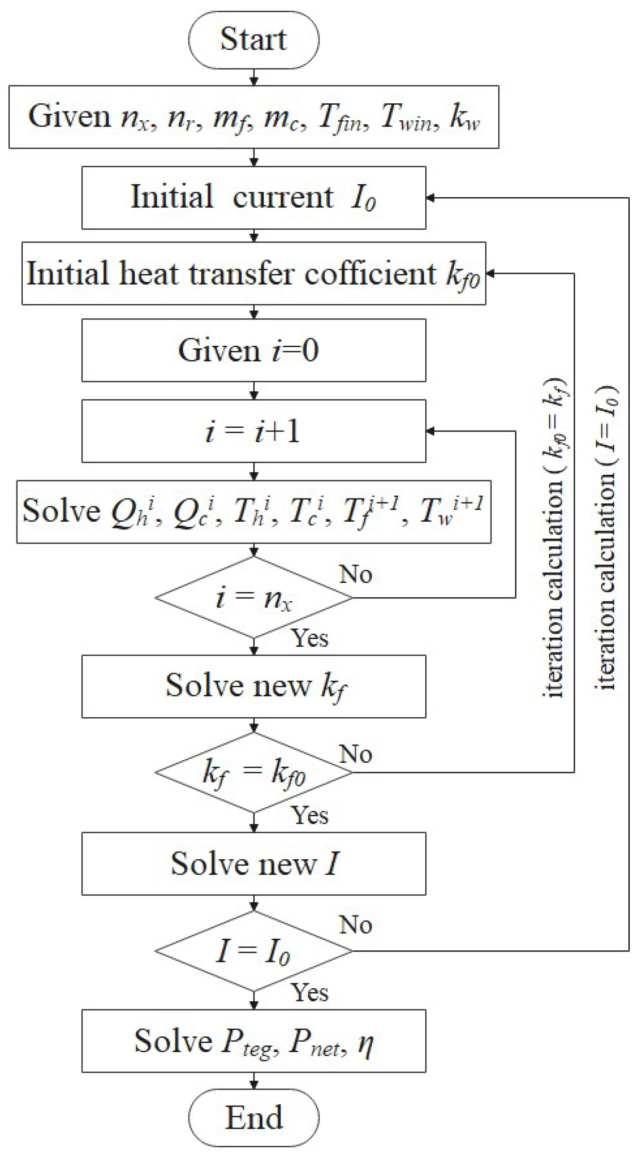
2.3. Solution Method
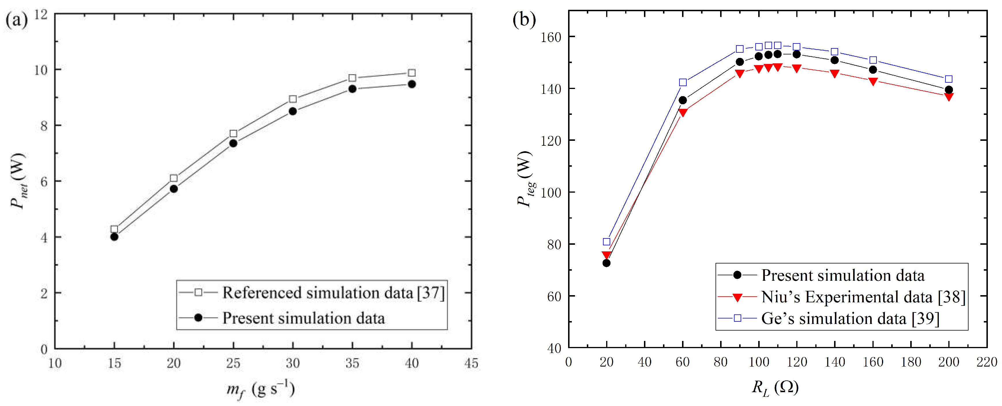
To solve the temperature distribution and heat distribution of ATEG using the numerical model developed in Section 2.2, the following equations were constructed from Equations (1)–(3):
[ 1 / c f m f 0 0 0 1 0 1 / n r 0 ( α p n i I + K p n i ) K p n i 0 0 1 / n r A h k f 0 1 0 0.5 0 0 1 / c w m w 0 0 0 1 0 1 / n r K p n i K p n i α p n i I 0 0 0 1 / n r A c k w 0 1 0 0.5 ] [ Q h i Q c i T h i T c i T f i + 1 T w i + 1 ] = [ T f i 0.5 I 2 R p n i 0.5 T f i T w i 0.5 I 2 R p n i 0.5 T w i ]
The total series current I of the CATEG is highly algebraically coupled to the nonlinear system of Equation (21), i.e., the temperature distribution of CATEG affects the series current I, and I affects the temperature distribution inside the thermoelectric generator at the same time; no analytical solution was obtained. Similar coupling relations exist between the TEG temperature field and the total heat transfer coefficient. A double iterative circular approximation approach was used to effectively solve such a multiple coupling numerical problem and the entire calculation process was solved using the Matlab program. The flowchart of the CATEG model solution procedure is shown in Figure 3.
First, the model parameters were provided and the initial guess I0 and kf0 initialization procedures were set. The initial temperature distribution within the CATEG was obtained by solving Equation (21). Based on this temperature distribution, Equation (10) was used to update kf, which was then used as the new kf0 for the next inner loop iteration. The process was repeated until the kf equaled the new initial kf0 of this iteration. Next, the new series current I was calculated using Equation (14) and used as the initial current I0 in the next iteration. This process was repeated until the new series current I equaled the initial current I0 of this iteration. Once the current, total heat transfer coefficient, and temperature distribution were determined, the power output, efficiency, and net power of CATEG was calculated using (15), (16), and (20).

3. Model Validation

In this section, the numerical results of the developed thermo-fluid-electric multi-physics field CATEG system model are validated with other numerical models and experimental data.
The numerical results of this model are compared with those of Yang et al. [37], who developed a numerical model of an ATEG applicable to a cylindrical heat source to comprehensively evaluate the optimal thermoelectric material structure size and maximum net power. To reproduce their data, we used the same ATEG parameter settings as in the literature in the model validation and set the hot end heat exchanger to a common cylindrical channel. Figure 4a depicts the variation in the ATEG maximum net power with hot fluid mass flow rate. The numerical simulation results in this study have a maximum error of 4.3% with Ref. [37]. This error is due to the fact that our model considers heat conduction through the ceramic and copper sheets, as well as the contact thermal resistance between the thermoelectric semiconductor and the heat exchanger, which were not considered in Ref. [37]. Furthermore, we improved the calculation method of the physical properties of the thermocouple, i.e., the Seebeck coefficient, thermal conductivity, and resistivity of the thermoelectric semiconductor are all highly dependent on temperature.
The numerical simulation results of this paper were compared with the experimental results as well as the numerical results of Ge et al. to further validate the developed CATEG numerical model. Niu et al. built an experimental thermoelectric generator set out of 56 commercially available Bi2Te3 thermoelectric modules combined with a flat plate heat exchanger and tested the power generation performance at various temperature differences [38]. Ge et al. proposed a new annular thermoelectric vaporizer that combined an air-heated vaporizer and thermoelectric power generation technology [39], and compared the simulation results with Niu’s experimental data. This is because, when the radius of the annular thermocouple is large enough, the inner arc of the thermoelectric leg corresponds to a small curvature and can be considered as a flat plate type thermocouple. The parameters from Ref. [38] were used for model verification. Figure 4b depicts the output performance of the thermoelectric generator under different loads. The error between the simulation data of Ge and the experimental results is less than 10%, whereas the error between the numerical simulation results in this study and the experimental data is around 7%. Although the numerical model established in this paper is a general thermoelectric generator mechanism model, there are still some discrepancies between simulation results and experimental data, which are primarily due to the model parameter settings limitations. First, the contact thermal resistance is set to 0.0008 m2∙K W−1 in the simulation; however, this is not provided in the experiment. Second, the density, dynamic viscosity, and Prandtl number of the heat source are highly dependent on temperature, which is not measured in the experiment but is set to a constant value in this model.

4. Results and Discussion

4.1. Effect of Different Cooling Methods on CATEG Thermoelectric Conversion Performance

The type of cooling fluid used in CATEGs for an automobile waste heat recovery system can be divided into air-cooling (ambient air used as cooling fluid during automobile operation) and water-cooling (coolant of the automobile engine cooling system). In regards to fluid flow direction, it can be divided into two ways: hot and cold fluid flowing in the same and reverse directions [33]. As a result, when the exhaust direction is fixed, the four most common cooling methods for an automobile thermoelectric generator system are cocurrent water-cooling (COW), cocurrent air-cooling (COA), countercurrent water-cooling (COUW), and countercurrent air-cooling (COUA). Since the convective heat transmission thermal resistance between the thermocouple and the ambient air (or water) is significantly lower than that between the thermocouple and the hot fluid [40], the heat transfer coefficient at the cold end is assumed to be constant. The cold side heat transfer coefficient kw is 100 W m−2 K−1 for air-cooling and 1000 W m−2 K−1 for water-cooling. Table 2 shows the specific parameters of the hot and cold fluids.
The variation in the power output and energy conversion efficiency of CATEG with the volume of thermoelectric semiconductor for different cooling methods is shown in Figure 5 and Figure 6, respectively. When compared to the cocurrent cooling method, the countercurrent cooling method increases the output power and efficiency of the thermoelectric generator; the percentage increase is also shown in the figures. This shows that the improved output power and efficiency by countercurrent water-cooling are lower than those improved by countercurrent air-cooling; when the total thermocouple volume is less than 2.66 × 10⁻⁴ m3, the increased percentage of output power and efficiency is lower and nearly the same for both cocurrent and countercurrent.
This is due to the fact that when the total thermocouple volume is small, the length of the CATEG is short, and cooling water flow direction has little influence on the temperature change at the TEG cold end; when the volume of the thermocouple increases, the use of countercurrent water-cooling can optimize the temperature distribution of the thermoelectric generator, i.e., obtain a more stable temperature difference to improve the output performance of the CATEG. Simultaneously, when using countercurrent air-cooling, the power output and energy conversion efficiency of the TEG are significantly improved as the thermocouple volume gradually increases, compared to cocurrent air-cooling. This is because the flow direction of air has a large impact on the cooling performance of the TEG: the mass flow rate of air is small compared to the cooling water, and the working temperature difference of the thermocouple decreases continuously when the exhaust gas and air flow in the same direction, whereas the countercurrent flow method can effectively maintain the stability of the working temperature difference of the ATECs and improve the thermoelectric conversion performance of the TEG. The greater the total volume of the thermocouple, the greater the output power and efficiency boosted by the counterflow of cold and hot fluids, and the percentage boosted by air-cooling is always greater than the percentage boosted by water-cooling. Furthermore, for each of the four cooling methods, there is an optimal thermocouple volume that produces the highest output power of the thermoelectric generator, and in general, the optimal volume is larger for water-cooling than air-cooling, and larger for countercurrent flow than cocurrent flow.
The variation in the working temperature difference ΔT of the thermocouple for the four different cooling methods are shown in Figure 7. The effect of the cocurrent flow and countercurrent flow methods on ΔT is small for water-cooling, but significant for air cooling. When using cocurrent air-cooling, ΔT decreases rapidly along the direction of fluid flow, whereas when using countercurrent air-cooling, the thermal energy transferred from the hot fluid to the cold side of the thermocouple gradually heats the air, resulting in a decreasing ΔT along the direction of air inflow; however, in general, the countercurrent flow method improves the operating temperature difference of the thermocouples and keeps the TEG at a higher output performance. When using cocurrent water-cooling, ΔT decreases rapidly along the direction of fluid flow, similar to the case of ACO; when using countercurrent water-cooling, ΔT also decreases continuously along the direction of exhaust gas flow, but at a faster rate than cocurrent flow. This is actually determined by the physical properties of hot and cold fluids, because the mass flow rate as well as the specific heat capacity of water are much greater than that of exhaust gas, regardless of whether the water is cocurrent or countercurrent flowing through the TEG, the temperature change is not too large, and thus has similar thermoelectric performance. Although the maximum temperature difference of COW is greater than that of COUW, the average working temperature difference of thermocouples in COUW is slightly greater than that of COW, and this difference is not obvious in practical applications.
As a result, when using air-cooling in the CATEG system, a distinction must be made between using the cocurrent flow or countercurrent flow method depending on the actual situation, whereas water-cooling does not require a distinction because the effect on thermoelectric properties is minor. On the other hand, the effect of different cooling methods on the hot side heat transfer coefficient within the CATEG can demonstrate this result. Figure 8 depicts the variations in total heat transfer coefficient at the hot end of the CATEG for different cooling methods, as well as the increased percentage obtained by the countercurrent flow method over that obtained by the cocurrent flow method. As shown, the hot side heat transfer coefficient decreases continuously as the thermoelectric semiconductor volume increases under the four cooling methods. The change in cooling fluid flow direction has very little effect on the heat transfer coefficient; the real reason for improved thermoelectric generator performance is that the countercurrent flow method increases the working temperature difference of the thermocouples, which increases efficiency and output power.

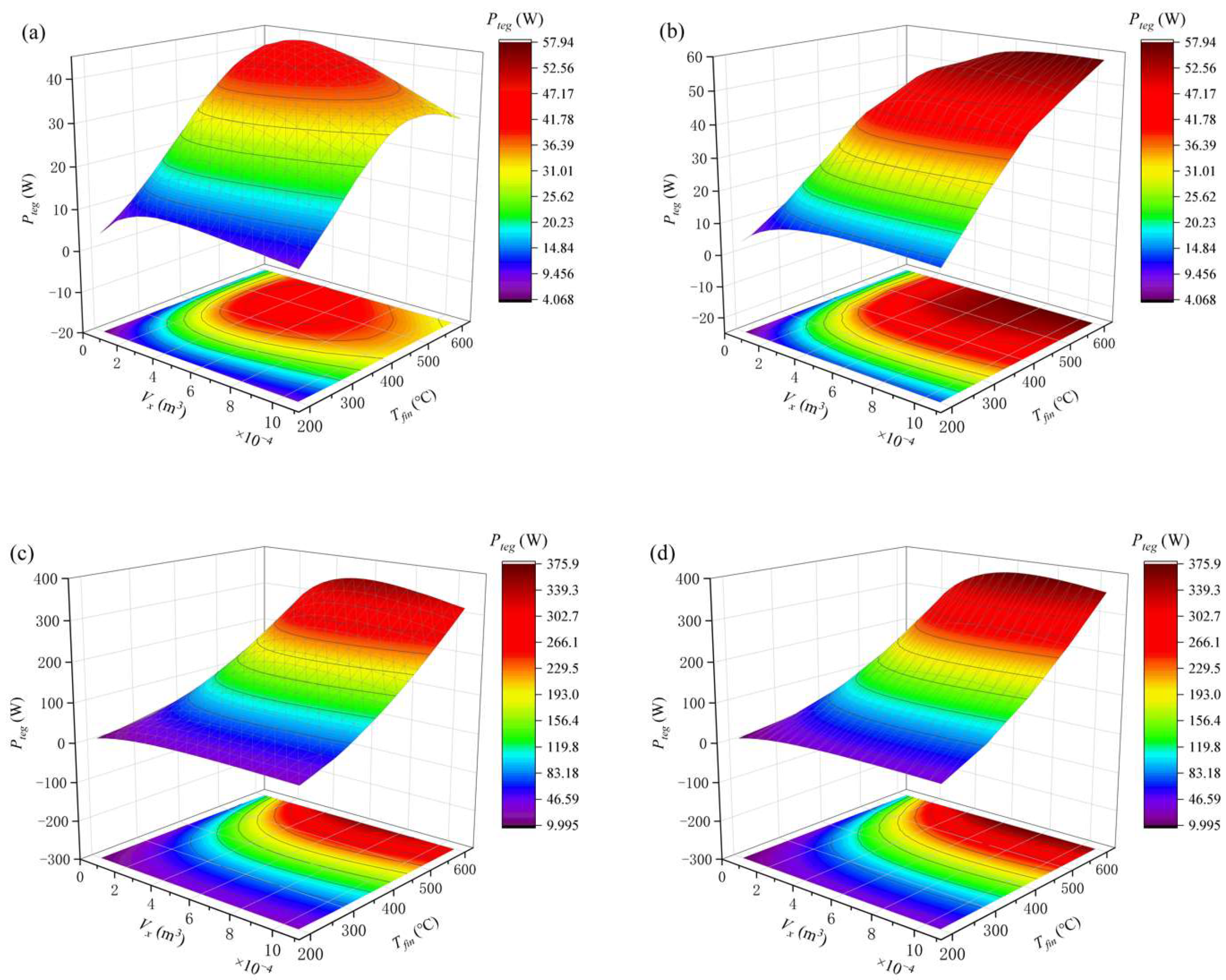
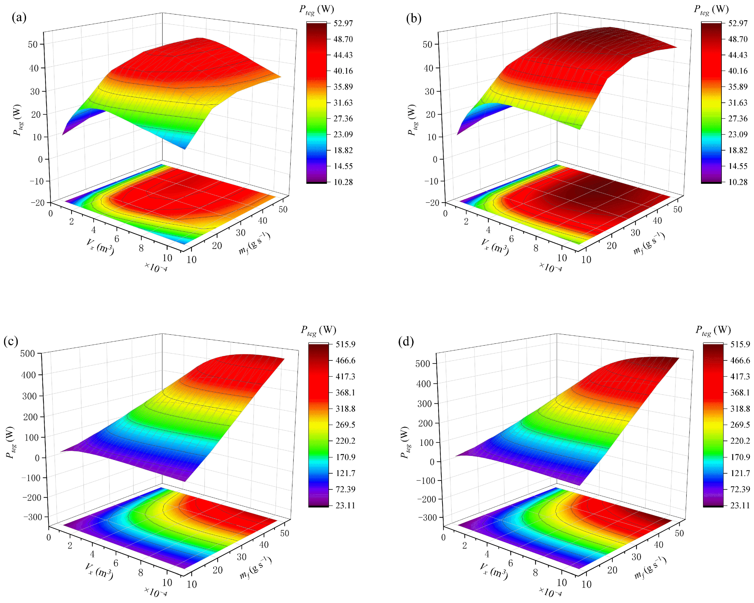
4.2. Effect of Various Exhaust Parameters on CATEG Performance under Four Different Cooling Methods

Section 4.1 discussed and analyzed the variation in CATEG output performance with total volume of thermoelectric semiconductors for different cooling methods; however, changes in vehicle operating conditions cause changes in exhaust parameters, which also have a significant impact on the thermoelectric performance of CATEG, and changes in engine exhaust back pressure caused by exhaust parameters’ fluctuation in a CATEG can also result in additional engine power loss. Therefore, it is critical to conduct an analysis of the effects of various automobile operating conditions on CATEG performance. According to Ref. [35], during vehicle operation, the exhaust gas temperature and mass flow rate vary with vehicle operating conditions within 200–600 °C and 10–50 g s−1, respectively, and this section evaluates the output performance of CATEG for various operating conditions and cooling methods.
The variation in CATEG power output for various exhaust gas temperatures under different cooling methods are shown in Figure 9. From Figure 9a,b, for the air-cooling method, the power output of the countercurrent method increases with the increase in thermoelectric semiconductor volume and then slowly decreases, and its maximum power output is significantly higher than that of the cocurrent flow method; the advantage of the countercurrent method becomes more apparent as the inlet temperature rises. Meanwhile, the optimal thermoelectric semiconductor volume corresponding to the maximum power output point is greater than that of the cocurrent flow method. The power output increases and then decreases as the thermoelectric semiconductor volume increases under the countercurrent flow method, and CATEG maintains a high output power for only a limited range of thermoelectric semiconductor volume. The optimal total thermoelectric volume is defined as the volume corresponding to the maximum output power point. The optimal total thermoelectric semiconductor volume for the countercurrent air-cooling (9.06 × 10⁻⁴ m3 for Pnet = 57.94 W) is greater than that of the cocurrent air-cooling (4.26 × 10⁻⁴ m3 for Pnet = 45.7 W). When using cocurrent air-cooling, the power output increases and then decreases as the heat source temperature rises, in contrast to the other three methods, which increase with increasing heat source temperature. Because of the presence of a large temperature gradient, the Seebeck coefficient and resistance of the PN couples along the direction of fluid flow continue to decrease during TEG operation, while heat transfer through the thermocouple increases. This temperature gradient characteristic becomes more apparent when the exhaust inlet temperature is higher. Although increasing the inlet temperature raises the working temperature difference of the thermocouple, which increases the output power, this power in the cocurrent air-cooling mode is insufficient to compensate for the power consumed by the thermoelectric semiconductors, resulting in a reduced output power. Figure 9c,d show that when water-cooling is used, the effect of the cocurrent and countercurrent methods on TEG thermoelectric performance is small; and the effect of exhaust inlet temperature on thermoelectric performance is similar under both cooling methods. The countercurrent flow method has a 5.5% higher maximum output power than the cocurrent flow method, which is consistent with the discussion in Section 4.1.
Figure 10 shows the variation in CATEG power output for various exhaust mass flow rates under different cooling methods. As shown in Figure 10a,b, the CATEG power output increases and then decreases with the rise in thermoelectric semiconductor volume for different exhaust gas mass flow rates under the air-cooling method; when the volume of the thermoelectric semiconductor remains constant, the output power increases quickly at first with increasing mass flow rate and then gradually decreases. When mf = 40 g s−1, the maximum power output of these two cooling methods can be obtained separately, but the maximum power point in the countercurrent method corresponds to a thermoelectric semiconductor volume of Vx = 5.86 × 10⁻⁴ m3, which is larger than that in the cocurrent flow method Vx = 4.26 × 10⁻⁴ m3, and the maximum output power of the countercurrent method is 13.2% higher than that of the cocurrent method.
According to Figure 10c,d, when using water-cooling, the power output increases first with increase in the volume of the thermoelectric semiconductor, and once the volume reaches a certain value, effective power boost cannot be obtained by further adding the thermoelectric element. The output power variation in the COW and COUW methods is nearly identical, but the maximum output power of the countercurrent flow is significantly greater than that of the cocurrent flow, especially at high mf (more than 20 g s−1). The mass flow rate of the exhaust gas has a significant influence on the electricity output of a water-cooling CATEG. When the volume of the thermoelectric semiconductor remains constant, the output power increases almost linearly as the mass flow rate increases. The optimal total thermoelectric semiconductor volume for the countercurrent water-cooling (1.06 × 10⁻³ m3 for Pnet = 515.9 W) is similar to that of the cocurrent water-cooling (9.59 × 10⁻⁴ m3 for Pnet = 466.08 W), and the maximum output power of the countercurrent method is 10.6% greater than that of the cocurrent method. The output power of the water-cooling is much higher compared to the air-cooling, regardless of fluid flow direction, especially at large mass flow rates.

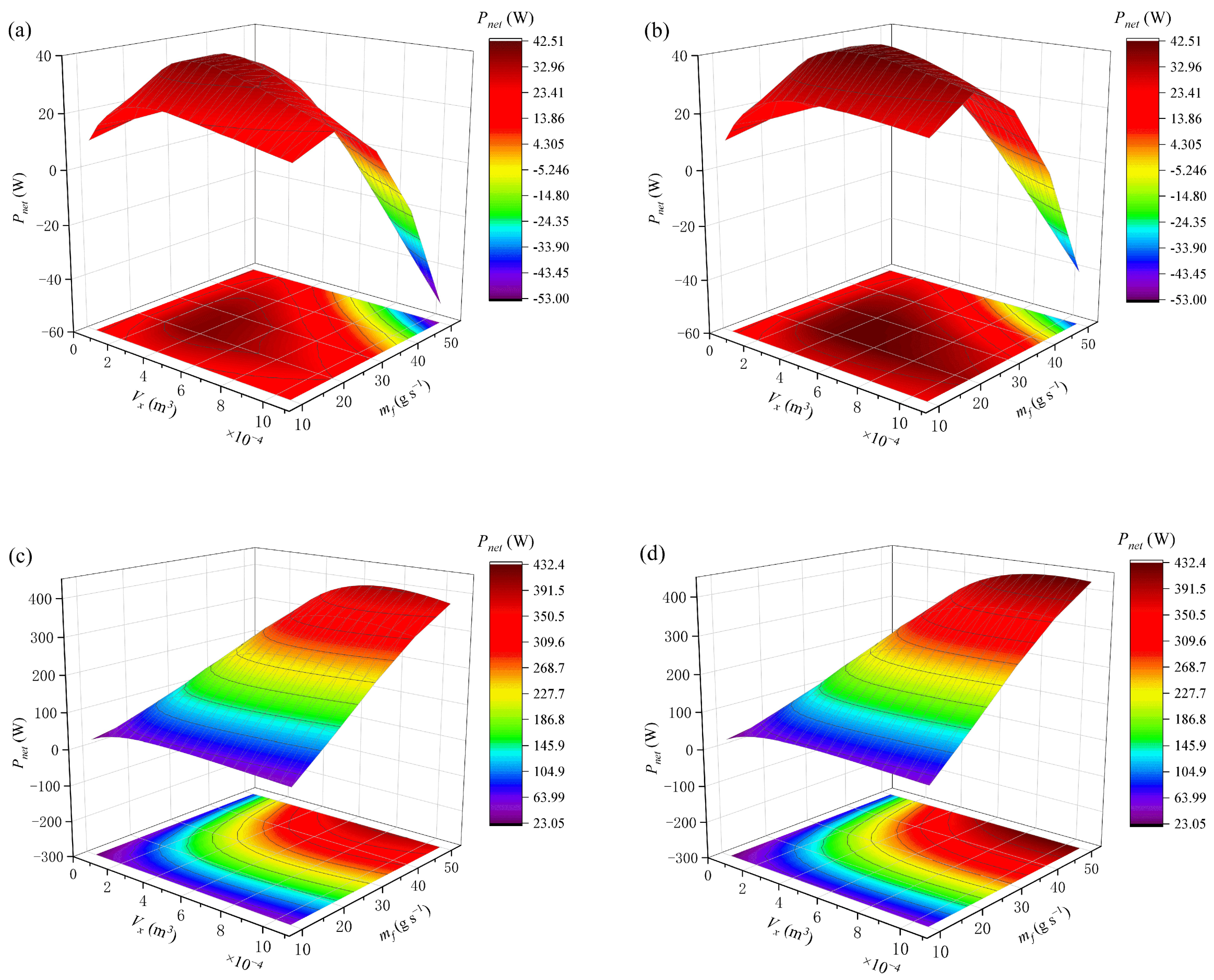
4.3. Effect of Exhaust Mass Flow Rates on CATEG Net Power under Four Different Cooling Methods

Although the output power of the countercurrent flow cooling method is higher than that of the cocurrent flow method, as previously discussed, a larger thermoelectric semiconductor volume is required to achieve optimal thermoelectric performance, implying a longer TEG length and a larger device volume, which will lead to an increase in the exhaust back pressure of the car engine, resulting in a decrease in net system power. Therefore, the effect of exhaust mass flow rate on net power of the CATEG system under different cooling methods will be investigated in this section.
Figure 11 shows the variation in CATEG net power for various exhaust gas mass flow rates under different cooling methods. The net power of the air-cooling CATEG increases and then decreases as the thermoelectric semiconductor volume increases, as shown in Figure 11a,b. The output power of the TEG at high mass flow rates is insufficient to compensate for the power loss to the system caused by high exhaust back pressure, resulting in a negative net power. The exhaust mass flow rate has a significant effect on the net power of CATEG, when the volume of the thermoelectric semiconductor remains constant; the net power increases with increasing mass flow rate and then rapidly decreases. When mf =20 g s−1, the maximum net power of these two cooling methods can be obtained separately; the maximum net power point in COUA method corresponds to a thermoelectric semiconductor volume of Vx = 5.33 × 10⁻⁴ m3, while in COA, its Vx = 4.26 × 10⁻⁴ m3; the maximum net power of the countercurrent method is 11.2% greater than that of the cocurrent method.
From Figure 11c,d, it can be seen that countercurrent flow or cocurrent flow has little effect on the net power of water-cooling in comparison to air-cooling. The optimal total thermoelectric semiconductor volume for the countercurrent water-cooling (9.06 × 10⁻⁴ m3 for Pnet = 432.42 W) is greater than that of the cocurrent water-cooling (7.46 × 10⁻⁴ m3 for Pnet = 396.87 W). Although the maximum net power is increased by 8.9%, the optimal thermoelectric semiconductor volume is increased by 21.4%; therefore, the economics of CATEG is slightly reduced. When the goal is to maximize CATEG net power, the determined optimal thermoelectric semiconductor volume is very different from that determined in Section 4.2; therefore, when designing and improving automobile exhaust TEG and choosing cooling methods, the impact of power loss caused by the engine exhaust back pressure on the TEG system should be considered.

5. Conclusions

In this study, a comprehensive variable physical property numerical model of CATEG using the finite element method was developed. The established theoretical model was validated using experimental data and other numerical simulation results. The maximum output power, net power, and optimal total thermoelectric semiconductor volume were calculated and compared for four different cooling methods with different exhaust parameters. The primary findings of the study are summarized below:
(1)
When compared to the cocurrent cooling method, the countercurrent cooling method can effectively improve the working temperature difference of the thermocouples, especially when using air-cooling, thereby increasing the output power; however, it requires more thermoelectric semiconductor volume to achieve maximum output power;
(2)
It is not preferable to use the cocurrent air-cooling method for the heat source with high temperature. As the temperature of the heat source rises, the output power of TEG increases first, then gradually declines after reaching a peak. For COUA, COW, and COUW, the output power rises almost linearly as the temperature of the heat source increases;
(3)
The exhaust mass flow rate has a significant influence on CATEG net power. The maximum net power Pnet = 432.42 W can be obtained using countercurrent water-cooling, corresponding to an optimal thermoelectric semiconductor volume of 9.06 × 10⁻⁴ m3. Compared to COW, the maximum net power increased by 8.9%, but the optimal thermoelectric semiconductor volume increased by 21.4%.

Author Contributions

Data curation, writing—original draft preparation, W.Y.; formal analysis, methodology, W.Z.; conceptualization, funding acquisition, writing—review and editing, Y.Y. and C.X.; validation, L.H.; visualization, Y.S. All authors have read and agreed to the published version of the manuscript.

Funding

This research was funded by the National Natural Science Foundation of China (51977164).

Institutional Review Board Statement

Not applicable.

Informed Consent Statement

Not applicable.

Data Availability Statement

All data, models, or code that support the findings of this study are available from the corresponding author upon reasonable request. The data are not publicly available as the data also forms part of an ongoing study.

Conflicts of Interest

The authors declare no conflict of interest.

Nomenclature

a1, a2, a3height, inner arc length, and thickness of the thermoelectric leg, mm
a4gap between p- and n-type semiconductors, mm
Cspecific heat capacity, J∙g−1∙K−1
Ddiameter, mm
Dhhydraulic diameter, m
FDarcy resistance coefficient
Hrsurface finish quality, m
Hconvective heat transfer coefficient, W∙m−2∙K−1
Icurrent, A
Ktotal heat transfer coefficient, W∙m−2∙K−1
Kthermal conductance, W∙K−1
Llength of the heat exchanger, m
mmass flow rate, g∙s−1
nrtotal thermocouple number in a single-ring
nxtotal thermocouple number in a line
NuNusselt number
ppressure, Pa
Ppower, W
PrPrandtl number
Qquantity of heat, W
rradius, m
Rresistance, Ω
ReReynolds number
Ttemperature, °C
Greek symbols
αthe Seebeck coefficient, V∙K−1
γdensity, kg∙m−3
δthickness, mm
difference
ηefficiency, %
λthermal conductivity, W∙m−1∙K−1
µdynamic viscosity, Pa∙s
ρresistivity, Ω∙m
Subscript
bconsumed pump value
ccold side of the thermoelectric generator
cerceramic
conconnector
cucopper
fhot fluid
favaverage value of hot fluid
hhot side of the thermoelectric generator
iinner ring of the hot end heat exchanger
Lexternal load
nn-type thermoelectric semiconductor
netnet value
oouter ring of heat exchanger
pp-type thermoelectric semiconductor
plateheat exchanger plate
pnthermocouple
tegTEG system value
wcold fluid
wavaverage value of cold fluid
Abbreviations
ATECannular thermoelectric couple
ATEGannular thermoelectric generator
CATEGconcentric annular thermoelectric generator
TEGthermoelectric generator

References

  1. Li, X.; Xie, C.; Quan, S.; Huang, L.; Fang, W. Energy management strategy of thermoelectric generation for localized air conditioners in commercial vehicles based on 48 V electrical system. Appl. Energy 2018, 231, 887–900. [Google Scholar] [CrossRef]
  2. Zhang, Z.; Zhang, Y.; Sui, X.; Li, W.; Xu, D. Performance of Thermoelectric Power-Generation System for Sufficient Recovery and Reuse of Heat Accumulated at Cold Side of TEG with Water-Cooling Energy Exchange Circuit. Energies 2020, 13, 5542. [Google Scholar] [CrossRef]
  3. Musharavati, F.; Khanmohammadi, S.; Nondy, J.; Gogoi, T.K. Proposal of a new low-temperature thermodynamic cycle: 3E analysis and optimization of a solar pond integrated with fuel cell and thermoelectric generator. J. Clean. Prod. 2022, 331, 129908. [Google Scholar] [CrossRef]
  4. Musharavati, F.; Khanmohammadi, S. Performance improvement of a heat recovery system combined with fuel cell and thermoelectric generator: 4E analysis. Int. J. Hydrogen Energy 2022, in press. [Google Scholar]
  5. Cho, Y.H.; Park, J.; Chang, N.; Kim, J. Comparison of Cooling Methods for a Thermoelectric Generator with Forced Convection. Energies 2020, 13, 3185. [Google Scholar] [CrossRef]
  6. Li, C.; Jiang, F.; Liu, C.; Liu, P.; Xu, J. Present and future thermoelectric materials toward wearable energy harvesting. Appl. Mater. Today 2019, 15, 543–557. [Google Scholar] [CrossRef]
  7. Kubenova, M.M.; Kuterbekov, K.A.; Balapanov, M.K.; Ishembetov, R.K.; Bekmyrza, K.Z. Some thermoelectric phenomena in copper chalcogenides replaced by lithium and sodium alkaline metals. Nanomaterials 2021, 11, 2238. [Google Scholar] [CrossRef] [PubMed]
  8. Bell, L.E. Cooling, heating, generating power, and recovering waste heat with thermoelectric systems. Science 2008, 321, 1457–1461. [Google Scholar] [CrossRef] [Green Version]
  9. Yin, L.-C.; Liu, W.-D.; Li, M.; Sun, Q.; Gao, H.; Wang, D.-Z.; Wu, H.; Wang, Y.-F.; Shi, X.-L.; Liu, Q.; et al. High Carrier Mobility and High Figure of Merit in the CuBiSe2 Alloyed GeTe. Adv. Energy Mater. 2021, 11, 2102913. [Google Scholar] [CrossRef]
  10. Ao, D.-W.; Liu, W.-D.; Chen, Y.-X.; Wei, M.; Jabar, B.; Li, F.; Shi, X.-L.; Zheng, Z.-H.; Liang, G.-X.; Zhang, X.-H.; et al. Novel Thermal Diffusion Temperature Engineering Leading to High Thermoelectric Performance in Bi2Te3-Based Flexible Thin-Films. Adv. Sci. 2022, 9, 2103547. [Google Scholar] [CrossRef]
  11. Li, X.; Xie, C.; Quan, S.; Shi, Y.; Tang, Z. Optimization of thermoelectric modules’ number and distribution pattern in an automotive exhaust thermoelectric generator. IEEE Access 2019, 7, 72143–72157. [Google Scholar] [CrossRef]
  12. Spriggs, P.; Wang, Q. Computationally Modelling the Use of Nanotechnology to Enhance the Performance of Thermoelectric Materials. Energies 2020, 13, 5096. [Google Scholar] [CrossRef]
  13. Shen, Z.-G.; Wu, S.-Y.; Xiao, L. Assessment of the performance of annular thermoelectric couples under constant heat flux condition. Energy Convers. Manag. 2017, 150, 704–713. [Google Scholar] [CrossRef]
  14. Chen, W.H.; Wu, P.H.; Lin, Y.L. Performance optimization of thermoelectric generators designed by multi-objective genetic algorithm. Appl. Energy. 2018, 209, 211–223. [Google Scholar] [CrossRef]
  15. Fan, L.; Zhang, G.; Wang, R.; Jiao, K. A comprehensive and time-efficient model for determination of thermoelectric generator length and cross-section area. Energy Convers. Manag. 2016, 122, 85–94. [Google Scholar] [CrossRef]
  16. Zhang, M.; Wang, J.; Tian, Y.; Zhou, Y.; Zhang, J.; Xie, H.; Wu, Z.; Li, W.; Wang, Y. Performance comparison of annular and flat-plate thermoelectric generators for cylindrical hot source. Energy Rep. 2021, 7, 413–420. [Google Scholar] [CrossRef]
  17. Zhu, W.; Weng, Z.; Li, Y.; Zhang, L.; Zhao, B.; Xie, C.; Shi, Y.; Huang, L.; Yan, Y. Theoretical analysis of shape factor on performance of annular thermoelectric generators under different thermal boundary conditions. Energy 2022, 239, 122285. [Google Scholar] [CrossRef]
  18. Weng, Z.; Liu, F.; Zhu, W.; Li, Y.; Xie, C.; Deng, J.; Huang, L. Performance improvement of variable-angle annular thermoelectric generators considering different boundary conditions. Appl. Energy 2022, 306, 118005. [Google Scholar] [CrossRef]
  19. Shen, Z.-G.; Liu, X.; Chen, S.; Wu, S.-Y.; Xiao, L.; Chen, Z.-X. Theoretical analysis on a segmented annular thermoelectric generator. Energy 2018, 157, 297–313. [Google Scholar] [CrossRef]
  20. Shittu, S.; Li, G.; Zhao, X.; Ma, X.; Akhlaghi, Y.G.; Ayodele, E. High performance and thermal stress analysis of a segmented annular thermoelectric generator. Energy Convers. Manag. 2019, 184, 180–193. [Google Scholar] [CrossRef]
  21. Wen, Z.F.; Sun, Y.; Zhang, A.B.; Wang, B.L.; Wang, J.; Du, J.K. Performance Analysis of a Segmented Annular Thermoelectric Generator. J. Electron. Mater. 2020, 49, 4830–4842. [Google Scholar] [CrossRef]
  22. Luo, D.; Wang, R.; Yu, W.; Sun, Z.; Meng, X. Modelling and simulation study of a converging thermoelectric generator for engine waste heat recovery. Appl. Therm. Eng. 2019, 153, 837–847. [Google Scholar] [CrossRef]
  23. Li, Y.; Wang, S.; Zhao, Y.; Lu, C. Experimental study on the influence of porous foam metal filled in the core flow region on the performance of thermoelectric generators. Appl. Energy 2017, 207, 634–642. [Google Scholar] [CrossRef]
  24. Yang, W.; Zhu, W.; Li, Y.; Zhang, L.; Zhao, B.; Xie, C.; Yan, Y.; Huang, L. Annular thermoelectric generator performance optimization analysis based on concentric annular heat exchanger. Energy 2022, 239, 122127. [Google Scholar] [CrossRef]
  25. Zhu, W.; Deng, Y.; Wang, Y.; Shen, S.; Gulfam, R. High-performance photovoltaic-thermoelectric hybrid power generation system with optimized thermal management. Energy 2016, 100, 91–101. [Google Scholar] [CrossRef]
  26. Li, B.; Huang, K.; Yan, Y.; Li, Y.; Twaha, S.; Zhu, J. Heat transfer enhancement of a modularised thermoelectric power generator for passenger vehicles. Appl. Energy 2017, 205, 868–879. [Google Scholar] [CrossRef]
  27. Jaworski, M.; Bednarczyk, M.; Czachor, M. Experimental investigation of thermoelectric generator (TEG) with PCM module. Appl. Therm. Eng. 2016, 96, 527–533. [Google Scholar] [CrossRef]
  28. Sajid, M.; Hassan, I.; Rahman, A. An overview of cooling of thermoelectric devices. Renew. Sust. Energ. Rev. 2017, 78, 15–22. [Google Scholar] [CrossRef]
  29. Meng, J.-H.; Wu, H.-C.; Wang, T.-H. Optimization of Two-Stage Combined Thermoelectric Devices by a Three-Dimensional Multi-Physics Model and Multi-Objective Genetic Algorithm. Energies 2019, 12, 2832. [Google Scholar] [CrossRef] [Green Version]
  30. Zhao, Y.; Fan, Y.; Ge, M.; Xie, L.; Li, Z.; Yan, X.; Wang, S. Thermoelectric performance of an exhaust waste heat recovery system based on intermediate fluid under different cooling methods. Case Stud. Therm. Eng. 2021, 23, 100811. [Google Scholar] [CrossRef]
  31. Luo, D.; Wang, R.; Yu, W.; Zhou, W. A numerical study on the performance of a converging thermoelectric generator system used for waste heat recovery. Appl. Energy 2020, 270, 115181. [Google Scholar] [CrossRef]
  32. He, W.; Wang, S.; Zhang, X.; Li, Y.; Lu, C. Optimization design method of thermoelectric generator based on exhaust gas parameters for recovery of engine waste heat. Energy 2015, 91, 1–9. [Google Scholar] [CrossRef]
  33. He, W.; Wang, S.; Lu, C.; Zhang, X.; Li, Y. Influence of different cooling methods on thermoelectric performance of an engine exhaust gas waste heat recovery system. Appl. Energy 2016, 162, 1251–1258. [Google Scholar] [CrossRef]
  34. Luo, D.; Sun, Z.; Wang, R. Performance investigation of a thermoelectric generator system applied in automobile exhaust waste heat recovery. Energy 2022, 238, 121816. [Google Scholar] [CrossRef]
  35. He, W.; Guo, R.; Liu, S.; Zhu, K.; Wang, S. Temperature gradient characteristics and effect on optimal thermoelectric performance in exhaust power-generation systems. Appl. Energy 2020, 261, 114366. [Google Scholar] [CrossRef]
  36. He, W.; Wang, S.; Li, Y.; Zhao, Y. Structural size optimization on an exhaust exchanger based on the fluid heat transfer and flow resistance characteristics applied to an automotive thermoelectric generator. Energy Convers. Manage. 2016, 129, 240–249. [Google Scholar] [CrossRef]
  37. Yang, Y.; Wang, S.; Zhu, Y. Evaluation method for assessing heat transfer enhancement effect on performance improvement of thermoelectric generator systems. Appl. Energy 2020, 263, 114688. [Google Scholar] [CrossRef]
  38. Niu, X.; Yu, J.; Wang, S. Experimental study on low-temperature waste heat thermoelectric generator. J. Power Sources 2009, 188, 621–626. [Google Scholar] [CrossRef]
  39. Ge, M.; Wang, X.; Zhao, Y. Performance analysis of vaporizer tube with thermoelectric generator applied to cold energy recovery of liquefied natural gas. Energy Convers. Manage. 2019, 200, 112112. [Google Scholar] [CrossRef]
  40. Zhou, Z.-G.; Zhu, D.-S.; Wu, H.-X.; Zhang, H.-S. Modeling, experimental study on the heat transfer characteristics of thermoelectric generator. J. Therm. Sci. 2013, 22, 48–54. [Google Scholar] [CrossRef]
Figure 1. CATEG schematic view: (a) the whole frame, (b) profile of CATEG, (c) 3D view and equivalent thermal resistance of an ATEC.
Energies 15 02231 g001
Figure 2. (a) Finite element analysis of the annular thermoelectric generator, (b) schematic of calculation unit with temperature definitions (cocurrent flow).
Energies 15 02231 g002
Figure 3. Flowchart of the CATEG model solution procedure.
Energies 15 02231 g003
Figure 4. Validation of the proposed ATEG numerical model. (a) Comparison with simulation data in [37] (Adapted with permission from Ref. [37]. 2019 Elsevier). (b) Comparison with experimental data in [38] (Adapted with permission from Ref. [38]. 2008 Elsevier) and simulation data in [39] (Adapted with permission from Ref. [39]. 2019 Elsevier).
Energies 15 02231 g004
Figure 5. Variations in CATEG output power with the total thermoelectric semiconductor volume under different cooling methods and the increased percentage obtained by the countercurrent flow method over that obtained by the cocurrent flow method.
Energies 15 02231 g005
Figure 6. Variations in CATEG energy conversion efficiency with the total thermoelectric semiconductor volume under different cooling methods and the increased percentage obtained by the countercurrent flow method over that obtained by the cocurrent flow method.
Energies 15 02231 g006
Figure 7. Variations in the working temperature difference ΔT of the thermocouple for the four different cooling methods.
Energies 15 02231 g007
Figure 8. Variations in the total heat transfer coefficient with the total volume of the thermoelectric semiconductor for different cooling methods.
Energies 15 02231 g008
Figure 9. Variations in CATEG power output for various exhaust gas temperatures under different cooling methods when mf = 20 g s−1: (a) cocurrent air-cooling, (b) countercurrent air-cooling, (c) cocurrent water-cooling, (d) countercurrent water-cooling.
Energies 15 02231 g009
Figure 10. Variations in CATEG power output for various exhaust gas mass flow rates under different cooling methods when Tfin = 400 °C: (a) cocurrent air-cooling, (b) countercurrent air-cooling, (c) cocurrent water-cooling, (d) countercurrent water-cooling.
Energies 15 02231 g010
Figure 11. Variations in CATEG net power for various exhaust gas mass flow rates under different cooling methods when Tfin = 400 °C: (a) cocurrent air-cooling, (b) countercurrent air-cooling, (c) cocurrent water-cooling, (d) countercurrent water-cooling.
Energies 15 02231 g011
Table 1. Detailed parameters and material properties of the CATEG.
ParametersDescriptionValueUnits
a1/a2/a3Height/thickness/inner arc length of the p(n)-type leg5/5/5mm
a4Distance between p-type leg and n-type leg1mm
δcerThickness of the ceramic sheet0.05mm
λcerThermal conductivity coefficient of ceramic35W m−1 K−1
δcuThickness of the copper sheet0.2mm
λcuThermal conductivity coefficient of copper398W m−1 K−1
δplateThickness of the exchanger plate1mm
λplateThermal conductivity coefficient of the exchanger plate398W m−1 K−1
αpSeebeck coefficient of the p-type semiconductorαp (T) = 161 × 10−4 − 1.818 × 10⁻⁶T + 1.11 × 10⁻⁸T2 − 2.035 × 10⁻¹¹T3 + 1.134 × 10⁻¹⁴T4V K−1
αnSeebeck coefficient of the n-type semiconductorαn (T) = −4.428 × 10⁻⁴ + 3.469 × 10⁻⁶T − 1.42 × 10⁻⁸T2 + 2.325 × 10⁻¹¹T3 − 1.3 × 10⁻¹⁴T4V K−1
λpThermal conductivity of the p-type semiconductorλp (T) = −46.97 + 0.457T − 1.575 × 10⁻³T2 + 2.331 × 10⁻⁶T3 − 1.242 × 10⁻⁹T4W m−1 K−1
λnThermal conductivity of the n-type semiconductorλn (T) = 10.12 − 7.414 × 10⁻²T + 2.246 × 10⁻⁴T2 − 3.019 × 10⁻⁷T3 − 1.537 × 10⁻¹⁰T4W m−1 K−1
ρpElectrical resistivity of the p-type semiconductorρp (T) = −5.01 × 10⁻⁵ + 3.519 × 10⁻⁷T − 7.74 × 10⁻¹⁰T2 + 8.94 × 10⁻¹³T3 − 4.32 × 10⁻¹⁶T4Ω·m
ρnElectrical resistivity of the n-type semiconductorρn (T) = −8.072 × 10⁻⁶ + 4.507 × 10⁻⁸T + 7.827 × 10⁻¹¹T2 − 2.305 × 10⁻¹³T3 + 1.317 × 10⁻¹⁶T4Ω·m
Table 2. Detailed parameters and properties of the hot and cold fluids.
NameDescriptionParameterValueUnit
Exhaust gasHeat transfer coefficientkfEquation (10)W m−2 K−1
Inlet temperatureTfin400°C
Mass flow ratemf20g s−1
Specific heat capacitycf1.12J g−1 K−1
Ambient airHeat transfer coefficientkw100W m−2 K−1
Inlet temperatureTwin30°C
Mass flow ratemw20g s−1
Specific heat capacitycw1.0J g−1 K−1
Cooling waterHeat transfer coefficientkw1000W m−2 K−1
Inlet temperatureTwin70°C
Mass flow ratemw200g s−1
Specific heat capacitycw4.177J g−1 K−1
Publisher’s Note: MDPI stays neutral with regard to jurisdictional claims in published maps and institutional affiliations.

