
Energy Comparison between a Load Sensing System and Electro-Hydraulic Solutions Applied to a 9-Ton Excavator


1
Department of Engineering and Architecture, University of Parma, 43124 Parma, Italy
2
Department of Energy, Politecnico di Torino, Corso Duca degli Abruzzi 24, 10129 Turin, Italy
*
Author to whom correspondence should be addressed.
Energies 2022, 15(7), 2583; https://0-doi-org.brum.beds.ac.uk/10.3390/en15072583
Submission received: 10 February 2022
/
Revised: 18 March 2022
/
Accepted: 31 March 2022
/
Published: 1 April 2022
(This article belongs to the Special Issue Application and Analysis in Fluid Power Systems)
Abstract
:With the increasingly stringent regulations on air quality and the consequent emission limits for internal combustion engines, researchers are concentrating on studying new solutions for improving efficiency and energy saving even in off-road mobile machines. To achieve this task, pump-controlled or displacement-controlled systems have inspired interest for applications in off-road working machines. Generally, these systems are derived from the union of a hydraulic machine coupled to an electric one to create compact components that could be installed near the actuator. The object of study of this work is a 9-ton excavator, whose hydraulic circuit is grounded on load sensing logic. The validated mathematical model, created previously in the Simcenter Amesim© environment, represents the starting point for developing electro-hydraulic solutions. Electric components have been inserted to create different architectures, both with open- and closed-circuit layouts, in order to compare the energy efficiency of the different configurations with respect to the traditional load sensing system. The simulations of a typical working cycle show the energy benefits of electro-hydraulic solutions that allow for drastically reducing the mechanical energy required by the diesel engine and, consequently, the fuel consumption. This is mainly possible because of the elimination of directional valves and pressure compensators, which are necessary in a load sensing circuit, but are also a source of great energy dissipations. The results show that closed-circuit solutions produce the greatest benefits, with higher energy efficiencies than the open-circuit solution. Furthermore, closed-circuit configurations require fewer components, allowing for more compact and lighter solutions, as well as being cheaper.
1. Introduction
The study of new solutions for improving energy efficiency and fuel saving applied to mobile off-road work machines is also due to the increasingly stringent regulations on emissions from internal combustion engines. Among the different proposals, some researchers have studied hybrid architectures to improve the energy efficiency of the transmission system. In the literature [1,2], solutions are presented to increase the energy efficiency of hydraulic systems, introducing architectures for energy recovery. In the case of an excavator, the most commonly used strategy is generally the recovery of kinetic energy given by the rotation of the swing and the potential energy of the arms; a complete discussion of these solutions can be found in [3,4,5].
Nowadays, in many engineering fields, the interest of researchers is aimed at the introduction of electro-mechanical actuation systems, replacing the traditional hydraulic architectures controlled by valves [6]. The distributed hydraulic solutions, replacing the centralized one, are derive from the aeronautical sector, where the thought of “more electric aircraft (MEA)” [7] is predominant, and is also spreading in various fields of application such as aeronautics [7], submarine [8], and land vehicles [9].
Electro-hydraulic systems could be achieved using electro-hydrostatic actuators (EHA) that combine compact dimensions and high energy efficiencies, while also offering the advantage of allowing plug-and-play installations. Many scientific papers compare EHA systems to traditional valve-controlled hydraulic architectures. Schmidt et al. [10] propose various solutions that provide pump control also with load holding characteristics. The distribution of energy and the possibility of energy recovery are described for all of the studied solutions, comparing the results with those of a traditional hydraulic system controlled by valves. Padovani et al. [11] suggest another electro-hydraulic drive system applied to single-rod cylinders with a passive load holding capability. Applying this architecture to a single-arm crane, the authors highlight how the error on the final position of the arm remains within ±2 mm, while the overall energy efficiency reaches about 60% during handling. Among the various applications in the aeronautical field, Takahashi et al. [12] have proposed an electro-hydraulic system applied to a single-rod double-acting actuator for the landing gear. Ketelsen et al. [13] carry out a detailed review of the scientific literature, including electro-actuated systems with variable displacement hydraulic pumps and solutions with variable speed electric motors, comparing the advantages and disadvantages of each architecture. The authors report the progressive trend towards solutions based on electric motors, moving further and further away from diesel engines. The EHA architecture also offers the possibility of recovering energy, with the further advantage of sharing it subsequently on several actuators.
Abekawa et al. [14] state that excavators are responsible for about 60% of the CO2 emissions produced by construction machinery. It follows that the implementation of new solutions in order to reduce the emission of greenhouse gases by excavators makes it possible to significantly decrease the amount of global CO2 emissions. Niraula et al. and Zhang et al. [15,16], focusing on 1-ton mini excavators, showed that an electro-hydraulic actuation system could lead to a reduction in energy consumption of up to 50% compared to the traditional system based on load sensing circuit architecture. Budden et al. [17] modified a 20-ton excavator by equipping it with a digital displacement pump instead of the swashplate machine. The results show a significant increase in productivity, associated with fuel savings.
This article presents further results of a research activity applied to a 9-ton excavator, on which various electro-hydraulic solutions have been analyzed. The results, in terms of mechanical energy and fuel consumption, have been compared with those obtained by the traditional load sensing architecture. The results have been obtained through simulations carried out using a mathematical model of the excavator created in the Simcenter Amesim© environment. The standard load sensing model of the machine, created with a lumped parameter approach, consists of modeling the diesel engine, the variable displacement main pump, the post compensated flow sharing distributors, and the kinematics of the front equipment. The model has been validated through extensive experimental activity, which made it possible to quantify fuel consumption during the work cycles [18,19,20,21,22,23,24,25].
The mathematical model of the excavator has been modified to study new EHA circuit architectures. In particular, an open-circuit and two closed-circuit solutions have been studied. The energy performance of all configurations has been compared with that of the load sensing system: the results show how the electro-hydraulic circuit solutions offer a significantly higher energy performance than a traditional valve-controlled system, allowing for savings on fuel consumption.
In the previous paper [26], the authors have already investigated an EHA architecture based only on an open-circuit solution; in that solution, the accumulator was connected to one side of the actuators where the lower average pressure occurs, obviously that solution has a drawback because the side at lower pressure can change with the duty cycle. In this paper, to overcome this limit, a shuttle valve has been added to connect the accumulator to the lower pressure side of the actuator [13,27,28,29]. Furthermore, in this paper, two closed-circuit solutions have been investigated, not considered in [26]. The first closed-circuit presented is similar to the open-circuit in order to make a reliable comparison. The second closed-circuit solution [13] presents a different architecture where a further control of a solenoid valve is requested. The methodology followed is that all the solutions investigated are always compared with the traditional load sensing circuit in terms of both mechanical energy and fuel consumption saving. The contribute of this paper is not in creating new circuit architectures, which are already known, as reported in the cited papers, but in the potential of the mathematical modeling that permits giving reliable information about the application of different solutions in a mobile machine like the excavator considered. This document is structured as follows. Section 2 describes the mathematical model of the standard load sensing hydraulic excavator. Section 3 describes the different circuit solutions based on EHA. The results of the simulations of all architectures are reported in Section 4. Section 5 presents the comparison between the standard model LS and EHA solutions. Finally, Section 6 reports the conclusions and future developments.
2. Mathematical Model of the Standard Hydraulic Excavator
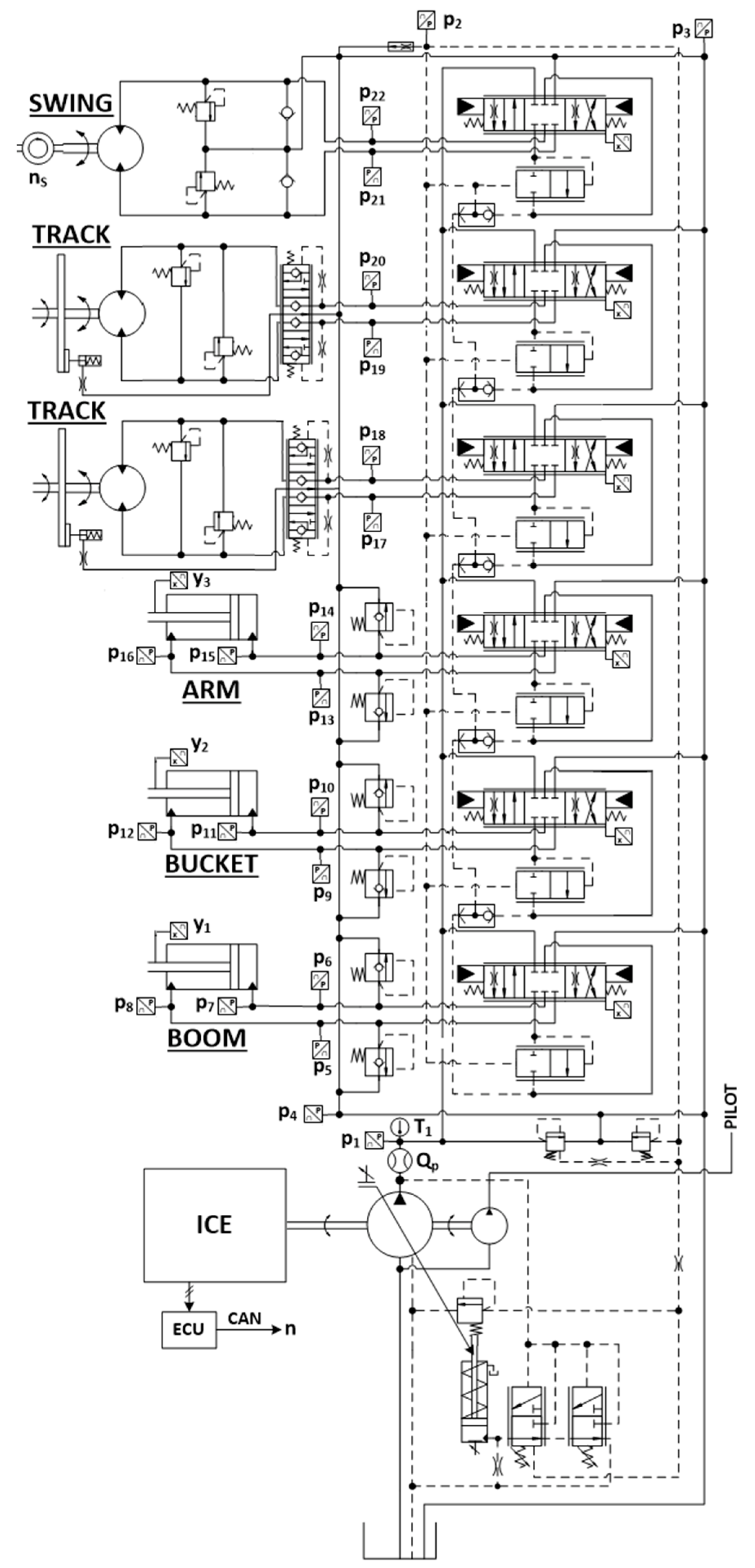
The machine under consideration is a 9-ton hydraulic excavator. The standard version features a 46-kW diesel (ICE) engine that drives an axial piston pump to feed a hydraulic circuit based on a load sensing logic (LS) with flow sharing distributors. The ISO diagram of the circuit layout of the machine is shown in Figure 1, where the several sensors used for the testing activity are also indicated. The mathematical model, based on a lumped parameter approach, has been developed in the Simcenter Amesim® environment. The complete and detailed description of the model can be found in previous publications [18,20,22,23].
As shown in the ISO diagram, the standard hydraulic circuit consists of two pumps. One is a fixed displacement machine with external gears, which feeds the circuit dedicated to pilots. The main pump that supplies the users is a variable displacement axial piston pump, equipped with a pressure compensator, flow compensator, and torque limiter. The pump has been modeled with a gray box approach, where the models of the regulators are white box, while a black box solution has been adopted for the pump flow characteristic, thanks to the use of hydromechanical and volumetric efficiency maps obtained from the experimental activity [25].
The directional valves are post compensated LS flow sharing valves, which allow for extracting the load sensing pressure to be sent to the pump regulators. The main feature of this type of valve is to maintain the same pressure drop in each section, even if the main pump reaches saturation conditions. The distributor model has been validated through the experimental results provided by the tests carried out in the laboratory of the Department of Engineering and Architecture of the University of Parma, Italy, as described in detail in [19,24].
The hydraulic cylinders are single rod double acting actuators. The model of every cylinder includes the effects of linear friction and leakage between the two chambers. The Coulomb and the viscous friction coefficients have been characterized by means of the experimental activity. The hydraulic cylinders have been simulated by applying the continuity equation and the fluid state equation for two control volumes, on the piston side and rod side. The model of the actuators has also remained unchanged in the further circuit solutions proposed in this article.
The kinematic model of the front attachment and of the swing has been developed in order to correctly calculate the forces and torques acting on the hydraulic actuators [21,24]. The front attachment consists of boom, arm, and bucket, which have been modeled as rigid bodies linked together by rotary joints and linear actuators. Characteristic properties such as mass, moment of inertia, and center of gravity have been defined using the CAD geometry of the components. For the swing model, assumed at constant inertia, both the Coulomb friction and viscous friction terms have been considered, defined through experimental tests carried out with fast and slow rotation cycles. In the different circuit solutions presented hereinafter in this article, the kinematic model has remained unchanged.
3. Electro-Hydraulics Solutions
The validated model of the excavator represents the starting point from which to develop EHA solutions for carrying out energy comparison. An open-circuit configuration introduced in a previous article [26] is re-proposed in this paper with the name “Open Circuit—Layout 1”, with a few changes regarding the position of the accumulator; moreover, two new closed-circuit configurations, called “Layout 2” and “Layout 3”, have been developed.
3.1. Open Circuit—Layout 1
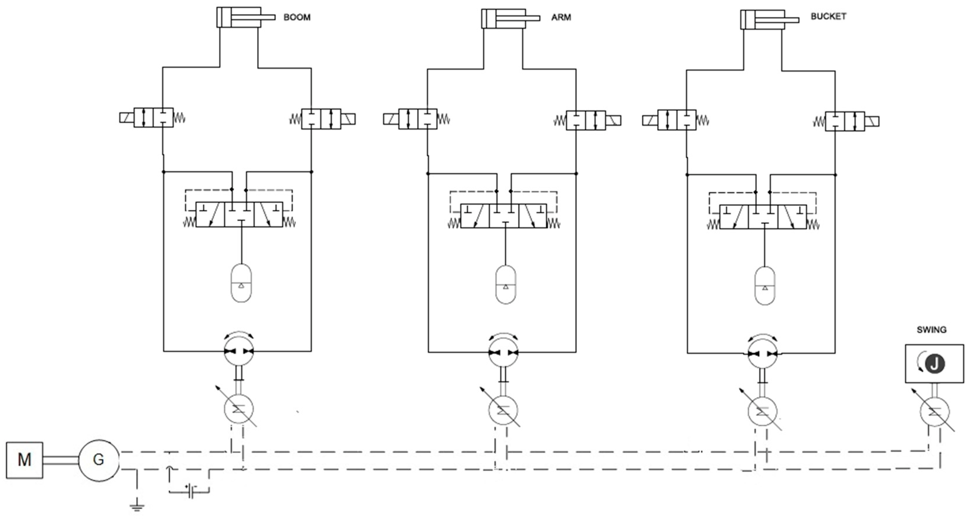
The circuit layout is shown in the ISO diagram in Figure 3: for each user, there is a pair of hydraulic machines with fixed displacement, connected to an electric unit, that can work as a pump or as a motor depending on the applied pressure difference. It has been supposed to move the swing by means of only an electric motor. The internal combustion engine, which is the same as in the standard excavator, drives an electric generator that supplies the energy necessary to power the electric motor of each user. The hydraulic machines have been supposed to be external gear units, and the models include maps of volumetric and hydromechanical efficiency as functions of speed and delivery pressure.
The sizing of each hydraulic machine has been set starting from the displacement of the actuator: the ratio between the displacement of the hydraulic machine on the piston side and on the rod side must be similar to the ratio between the active surfaces of the actuator; in general, it is advisable to keep the difference between these ratios below 2% [30,31]. As the displacements of the hydraulic machines are not exactly the same as those of the cylinder and that the internal losses of each component are also considered, a hydraulic accumulator has been introduced to compensate for the differences in flow rate. The accumulator is connected to the side with the lowest pressure by means of a shuttle valve. In case of overrunning load, the hydraulic motor allows for recovering energy, as the electric unit can work as a generator. For this reason, it is necessary to introduce a battery to store the energy produced.
For each side of the actuator, there are electrically controlled on/off valves to block the load, with the pressure drop included. They are powered only when it is necessary to move the cylinder. For safety reasons, the valves are provided with a spring that blocks the load, even in the case of a fault in the electrical power supply system.
3.2. Closed Circuits
Two different circuit solutions based on EHA architecture are proposed, and the results have been compared with those of the standard LS circuit and of the open-circuit. The proposed configurations are closed-circuit layouts. The feature common to all layouts is the presence of a bidirectional fixed displacement hydraulic pump, driven by an electric motor, and for every cylinder, the connection of the pump delivery port with the rod side or the piston side of the actuator is managed by the direction of rotation of the electric motor. Electric motors are powered by a generator driven by the internal combustion engine, the model of which is the same as in the standard excavator. An electric motor has been inserted in place of the hydraulic motor to move the swing and the tracks have not been considered. All of the proposed solutions permit removing the variable displacement main pump and the directional valves, typical of the standard LS system.
The hydraulic machines are bi-directional external gear pumps and have been modeled considering volumetric and hydromechanical efficiency maps as a function of rotation speed and delivery pressure. The pumps and their electric motors are the same for all proposed configurations.
The presence of different areas between the rod side and the piston side in the actuators makes it essential to balance the differential flow. The two solutions differ in the strategy in order to obtain the flow compensation.
3.3. Closed Circuit—Layout 2
Figure 4 shows the ISO scheme of Layout 1. The solution uses a flushing valve that connects the low-pressure chamber of the cylinder with the accumulator to compensate for the uneven flow rate given by the differential actuator [13]. When the piston side is fed, the higher flow rate required by the pump depressurizes the rod side chamber; the valve switches in order to connect the accumulator with the rod side, which provides the missing flow rate to the pump. Conversely, when the rod side is powered, the excess flow rate from the piston side is introduced into the accumulator.
In the case of an overrunning load, the hydraulic machine works as a motor and drives the electric machine, which, acting as a generator, allows energy to be recovered, storing it in the battery.
Two block valves have been inserted, similarly to the open-circuit layout, to ensure the position of the actuator even in the event of power failure. These on/off valves are opened only when it is necessary to move the cylinder.
3.4. Closed Circuit—Layout 3
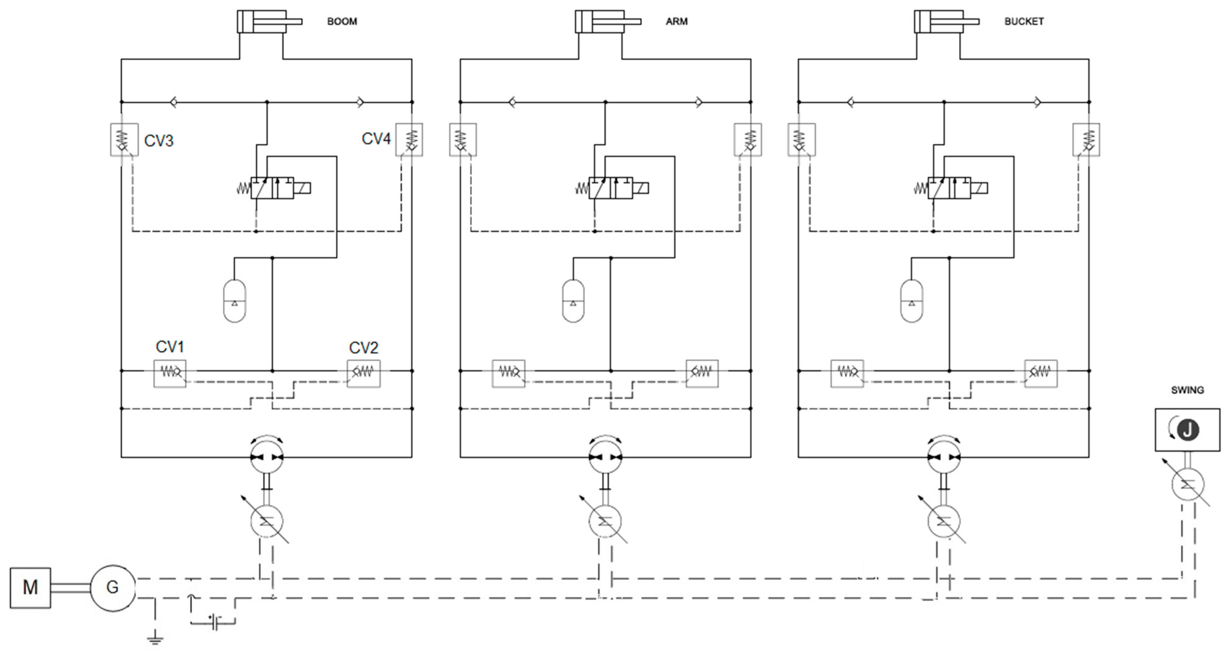
Figure 5 shows the circuit diagram of Layout 3. This solution has been reported by Padovani et al. [13]. Each user consists of an electric motor and a fixed displacement hydraulic machine driving the double-acting single-rod cylinder, in a closed-circuit layout.
The differential flow managed by the low-pressure accumulator is controlled by two piloted check valves (CV1 and CV2). There are also two pilot operated check valves (CV3 and CV4) for load holding, which, unlike Layout 1, are fully hydraulic valves. The actuation of the solenoid valve transmits the signal of the maximum pressure of the actuator to the pilot line to allow for the opening of the two load holding valves to permit the movement of the actuator. When the solenoid valve is not powered, the piloting line of the load holding valves is connected to the low-pressure line and does not allow for their opening. In the event of a power failure, the solenoid valve assumes this latter position by means of a spring, preventing the movement of the load.
The next sections describe the features common to all of the proposed EHA configurations.
3.5. Model of the Operator
The digging duty cycle defined by the JCMAS standard is replicated by the operator model. In the standard model of the excavator, the position of the actuator is compared with the desired position and, consequently, the opening of the directional valve is defined.
In all of the proposed EHA solutions, the position of the actuator depends on the flow rate delivered, given by the rotation speed of the hydraulic machine: the error between the desired position and the actual one controls the speed of the electric motor by means of a PI type controller, as indicated in Figure 6.
3.6. Electric Components
The electrical circuit is a feature common to all studied EHA configurations. It consists of three electric machines, a battery, and a generator connected to the diesel engine.
To allow for energy recovery during the overrunning load phases, it is essential to introduce a battery, which has been simulated as an ideal storage system without considering its dynamic behavior or thermal effects. The data shown in the Table 1 refer to a li-ion battery with characteristics that can be found in the scientific literature [32].
The electric machine model present in Amesim© allows for operating in all four quadrants of the torque-speed map: the electric machine can act as a generator, producing electricity that is then stored by the battery. In the operating range of the electric machines, a constant average efficiency has been assumed.
The main characteristics of the electrical components, which are the same for all of the analyzed configurations, are shown in Table 1.
4. Results
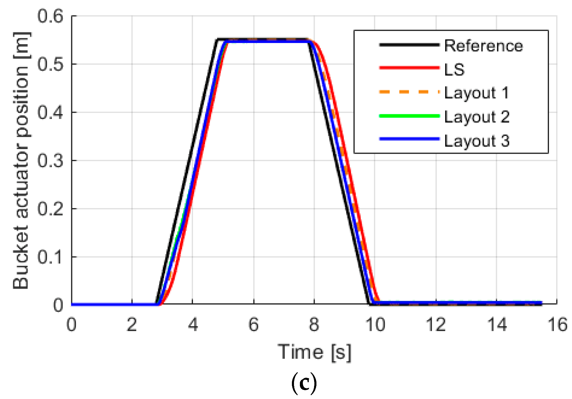
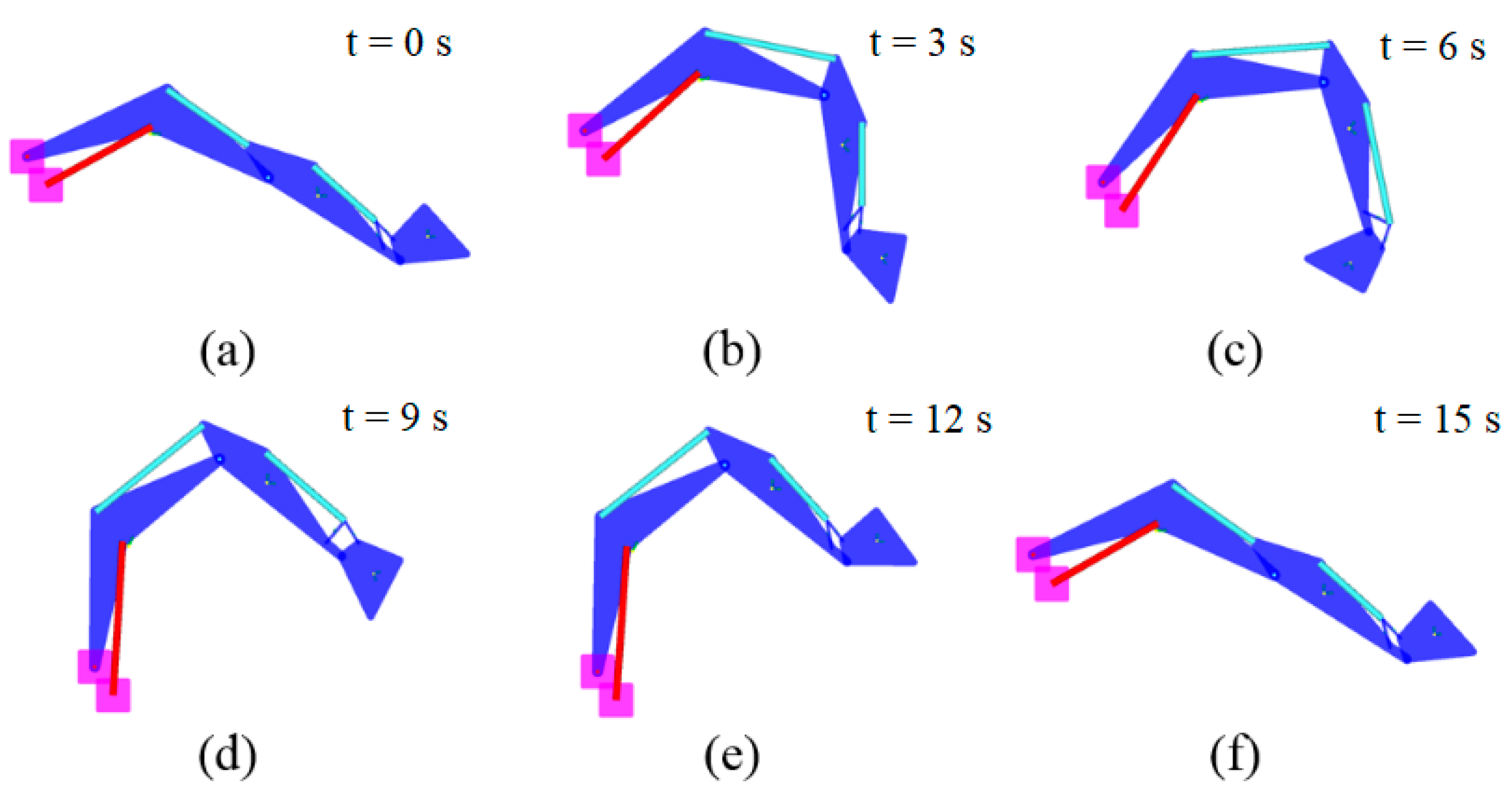
This section presents the results obtained with the standard LS circuit and EHA models to compare their performance. Figure 7 shows the position of the actuators of the front attachment during the imposed digging cycle. As can be appreciated from the graphs, all of the analyzed configurations are able to follow the duty cycle, without significant differences compared to the reference one. This result will allow for a reliable comparison of the fuel consumption between the various architectures. Figure 8, obtained from the Amesim© environment, shows the sequence of the positions of the front implement cylinders during the digging cycle, which consists of lowering the arms to dig an earth bucket and, in the subsequent extension, to unload the bucket and return it to the initial position.
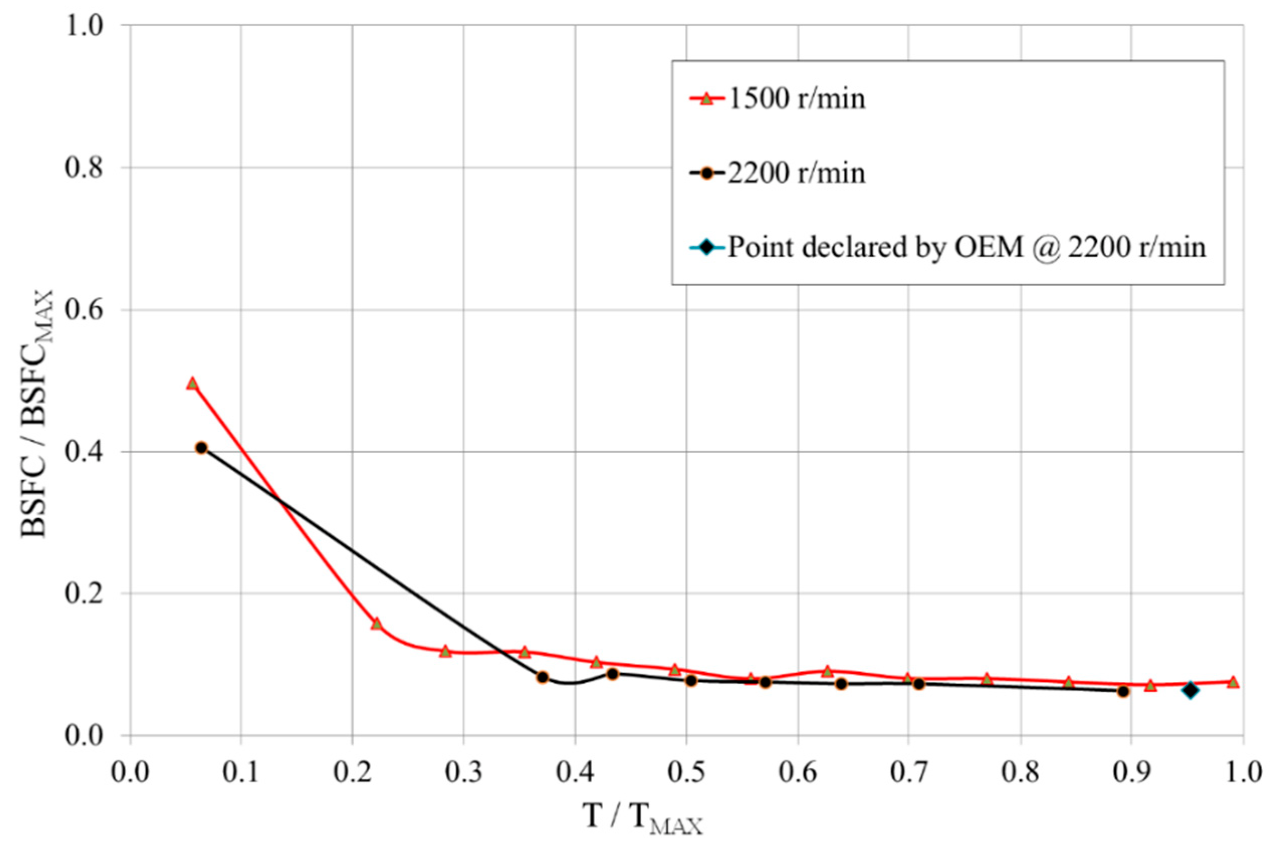
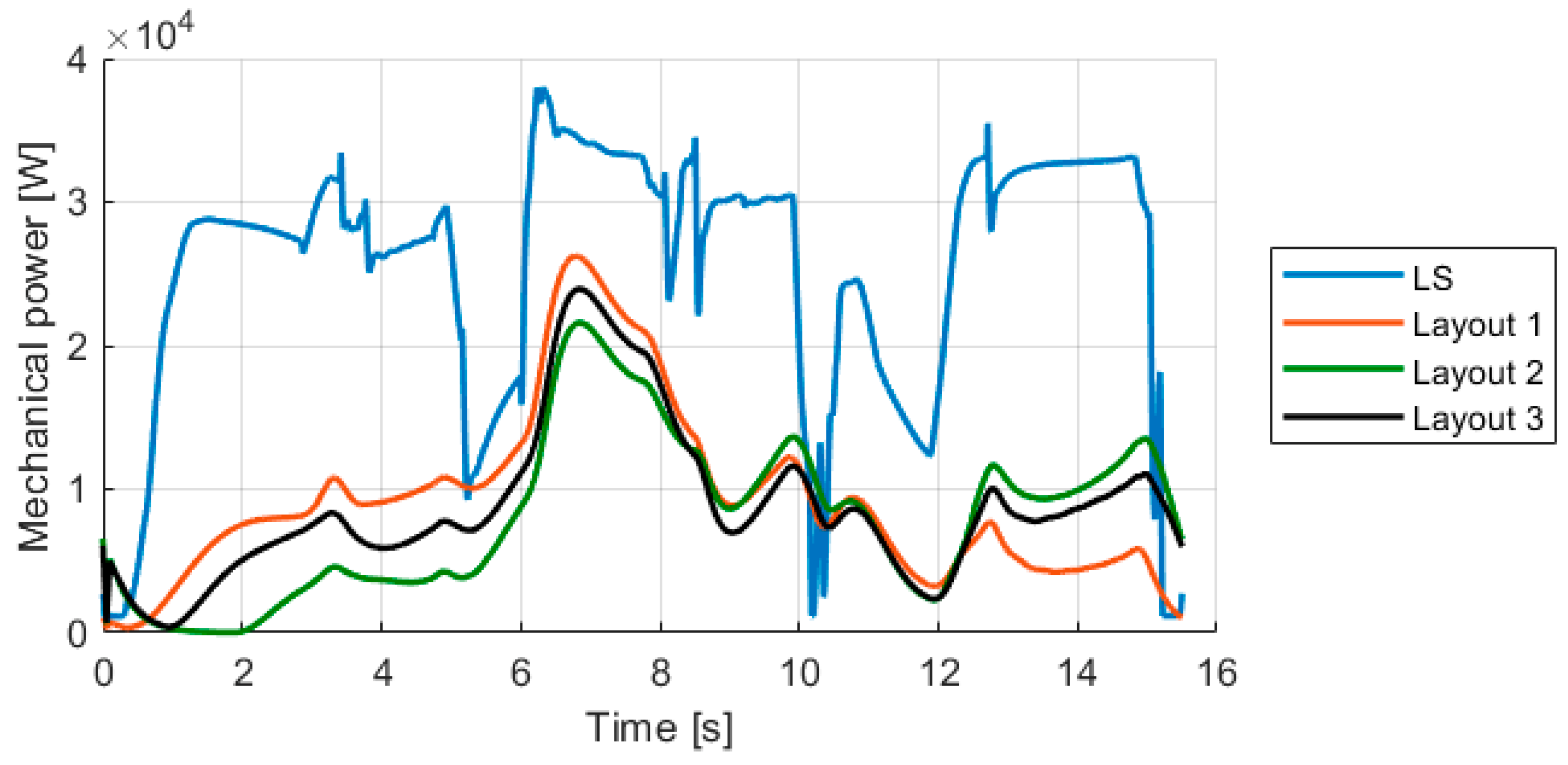
The simulations have been used to compare the energy demands of the different studied solutions. Table 2 shows the mechanical energy supplied by the diesel engine and required by the pumps for each configuration: for the LS solution, the value represents the energy required by the main pump, while for the EHA solutions, the values are the ones needed by the alternator. The results obtained show that EHA solutions allow for greatly reducing the mechanical energy required, with savings of over 60% for all of the configurations, mainly due to the absence of pressure compensators and directional valves, typical of the load sensing systems. In particular, the closed-circuit solutions allow for obtaining higher improvements than the open-circuit solution. Furthermore, Layout 2 permits a mechanical energy saving of 2% higher than that of Layout 3. These trends are also confirmed by analyzing the fuel savings. Table 3 shows the fuel consumption of the diesel engine for each layout, and this involves considering the engine efficiency map. The savings are also significant in terms of fuel, but with lower percentage values than for the mechanical energy saving: this is because the efficiency of the thermal engine strongly depends on the absorbed torque value. During the cycle, the power required by the diesel engine for EHA solutions is lower than the traditional LS circuit, as shown in Figure 9: in general, the internal combustion engine has lower efficiency if subjected to lower loads. The lower power required by the solutions studied opens up the possibility of downsizing the diesel engine: this solution would allow for even greater fuel saving to be obtained, because it would permit the engine to work at average loads closer to the maximum, where the efficiency is higher. The possibility of downsizing the diesel engine has not been investigated in this paper, but interesting results are reported in [26], applied to an open-circuit EHA solution.
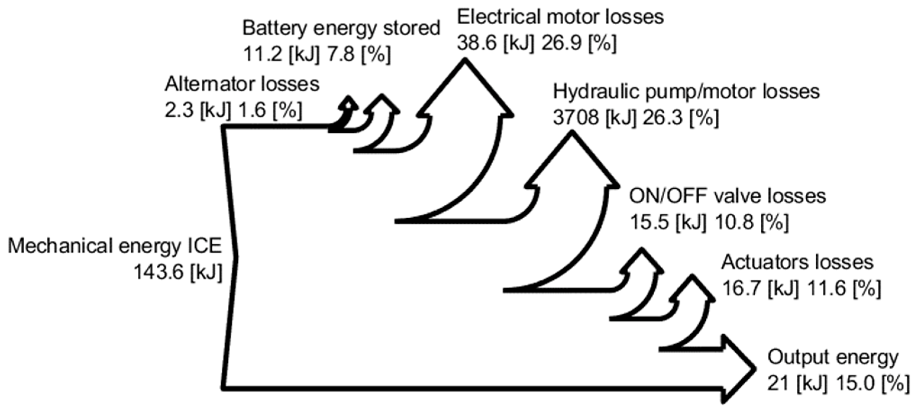
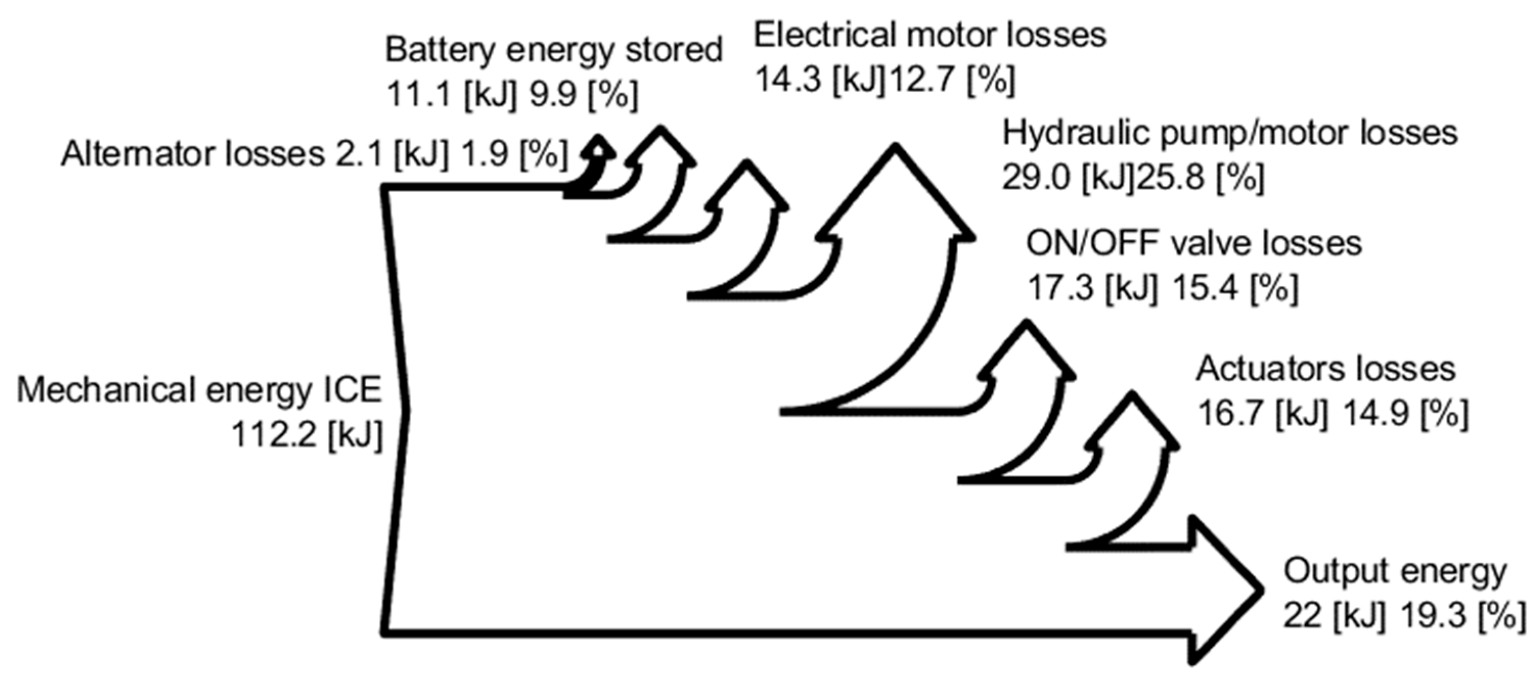
The Figure 10, Figure 11, Figure 12 and Figure 13 show the Sankey diagrams for all of the studied configurations, which show the distribution of the mechanical input energy on the different components that make up the circuit, allowing for quantifying the energy losses. In the LS standard configuration, in Figure 10, the largest amount of energy loss is attributable to the valve block, which dissipates more than 57% of the energy. The open-circuit EHA solution, in Figure 11, has most of the energy losses concentrated in the group consisting of electric and hydraulic machines. The closed-circuit variants, on the other hand, have similar energy distributions, as seen in Figure 12 and Figure 13, with lower losses than the open-circuit solution. In particular, Layout 3 has less energy losses on hydraulic machines than Layout 2, but at the same time, has much greater losses on the load holding valves, as the piloted check valves generate higher pressure drops than the on/off valves used in Layout 2.
5. Discussion
This research activity focused on the application of electro-hydraulic solutions to a 9-ton excavator to achieve energy improvements.
The results are obtained through simulations carried out in the Amesim© environment, starting from a validated mathematical model of an excavator in LS logic, used as a reference. Three EHA configurations have been considered, one in open-circuit configuration and two in closed-circuit configuration.
The energy distributions obtained through the Sankey diagrams for the traditional LS system and for the EHA configurations (open- and closed-circuit) have been determined for a 9-ton excavator. It has been shown that all EHA solutions allow for reducing the mechanical energy requirement by over 60%, mainly due to the elimination of the direction valves required by the traditional load sensing circuit. Furthermore, closed-circuit solutions show greater benefits than the open-circuit solution. The circuit layout therefore strongly influences the efficiency and overall consumption of the system and must be carefully designed. The closed-circuit solutions do not only bring advantages in energy terms. In fact, the open-circuit solution involves the use of two hydraulic machines for each actuator, which involves a much greater cost, size, and weight than the closed-circuit solutions. From these points of view, the Layout 2 solution allows for reducing the number of components, also guaranteeing the best energy performance.
However, although closed-circuit solutions have fewer components, they still suffer from the main drawback typical of all EHA solutions, which is the higher cost. In fact, electric motors, alternators, and a battery (or supercapacitors) are required, as well as electro-systems, to manage the electric drives that make this technology less competitive at present compared with fully hydraulic solutions. Despite this, the advantages presented in this article could help overcome these disadvantages.
The presented results evaluate the energy efficiency of all circuit solutions through the application of characteristic work cycles: during the simulations, the digging cycle defined by the JCMAS standard has been used [33], which takes place without a payload.
This simulation work made it possible to demonstrate the potential of electro-hydraulic solutions by applying them to a medium-sized excavator. Future developments will concern the study of other solutions for compensating the different flow rate given using a differential cylinder.
A further important result is that the mechanical power required by the diesel engine always has lower values than the standard LS circuit. A future development is represented by the study of the possibility of reducing the size of the diesel engine: in this way, the engine would always operate in working points with the highest efficiency, with the advantage of further reducing fuel consumption.
6. Conclusions
This article presents the results from the application of electro-hydraulic actuation (EHA) applied to a 9-ton excavator. A validated mathematical model of the traditional excavator with load sensing circuit has been taken as a reference for subsequent energy analyses. Three EHA configurations have been also considered: the first in open-circuit layout and the other two in closed-circuit layouts. The results of the simulations permit to quantify the possible energy saving given by each studied solution and to characterize in detail the sources of energy losses.
The standard load sensing circuit features directional valves with pressure compensators, which are a source of great energy losses. EHA solutions, on the other hand, make it possible to eliminate these components, significantly reducing hydraulic losses and allowing for considerable fuel savings.
In all of the EHA solutions studied, the mechanical power required by the diesel engine has lower values compared to the LS standard circuit: this interesting result provides the starting point for future developments where it is possible to reduce the displacement of the diesel engine, allowing for increasing its efficiency with the advantage of further reducing fuel consumption.
Author Contributions
Conceptualization, P.C.; methodology, P.C. and M.R.; software, F.S.; validation, P.C. and F.S.; writing—original draft preparation, P.C., F.S. and C.M.V.; writing—review and editing, P.C., F.S., C.M.V. and M.R.; supervision, P.C.; project administration, P.C. All authors have read and agreed to the published version of the manuscript.
Funding
This research received no external funding.
Data Availability Statement
Not applicable.
Acknowledgments
The authors would like to acknowledge the active support of this research by Casappa S.p.A., Parma, Italy.
Conflicts of Interest
The authors declare no conflict of interest.
Nomenclature
| Abbreviation | Definition |
| EHA | Electro-hydraulic actuator |
| CAD | Computer-aided design |
| ICE | Internal combustion engine |
| JCMAS | Japan Construction Machinery Association Standard |
| LS | Load sensing |
References
- Vukovic, M.; Leifeld, R.; Murrenhoff, H. Reducing Fuel Consumption in Hydraulic Excavators—A Comprehensive Analysis. Energies 2017, 10, 687. [Google Scholar] [CrossRef] [Green Version]
- Inderelst, M.; Weidner, F.D.; Stammen, C. Quantification of Energy Saving Influencers. 21t Excavator Hydraulic System—A Holistic Investigation? In Proceedings of the 11th International Fluid Power Conference, Aachen, Germany, 19–21 March 2018. [Google Scholar]
- Joo, C.; Stangl, M. Application of Power Regenerative Boom system to excavator. In Proceedings of the 10. IFK: International Fluid Power Conference, Dresden, Germany, 8–10 March 2016; Volume 3, pp. 175–184. [Google Scholar]
- Li, J.; Zhao, J.; Zhang, X. A Novel Energy Recovery System Integrating Flywheel and Flow Regeneration for a Hydraulic Excavator Boom System. Energies 2020, 13, 315. [Google Scholar] [CrossRef] [Green Version]
- Guan, C.; Xu, X.; Lin, X.; Wang, S.-H. Recovering system of swing braking energy in hydraulic excavator. Zhejiang Daxue Xuebao (Gongxue Ban)/J. Zhejiang Univ. (Eng. Sci.) 2012, 46, 142–149. [Google Scholar] [CrossRef]
- Padovani, D.; Rundo, M.; Altare, G. The Working Hydraulics of Valve-Controlled Mobile Machines: Classification and Review. J. Dyn. Syst. Meas. Control 2020, 142, 070801. [Google Scholar] [CrossRef]
- Rosero, J.A.; Ortega, J.A.; Aldabas, E.; Romeral, L. Moving towards a more electric aircraft. IEEE Aerosp. Electron. Syst. Mag. 2007, 22, 3–9. [Google Scholar] [CrossRef] [Green Version]
- Smith, S.; Irving, J.; Irving, J. Electro Hydrostatic Actuators for Control of Undersea Vehicles. In Proceedings of the Joint Undersea Warfare Technology Fall Conference, Groton, CT, USA, 11–14 August 2016. [Google Scholar]
- Schneider, M.; Koch, O.; Weber, J. Green Wheel Loader—Improving fuel economy through energy efficient drive and control concepts. In Proceedings of the 10th International Fluid Power Conference, Dresden, Germany; 2016. [Google Scholar]
- Schmidt, L.; Ketelsen, S.; Brask, M.H.; Mortensen, K.A. A Class of Energy Efficient Self-Contained Electro-Hydraulic Drives with Self-Locking Capability. Energies 2019, 12, 1866. [Google Scholar] [CrossRef] [Green Version]
- Padovani, D.; Ketelsen, S.; Hagen, D.; Schmidt, L. A Self-Contained Electro-Hydraulic Cylinder with Passive Load-Holding Capability. Energies 2019, 12, 292. [Google Scholar] [CrossRef] [Green Version]
- Takahashi, N.; Kondo, T.; Takada, M.; Masutani, K.; Okano, S.; Tsujita, M. Development of Prototype Electro-Hydrostatic Actuator for Landing Gear Extension and Retraction. In Proceedings of the 7th JFPS International Symposium on Fluid Power, Toyama, Japan, 15–18 September 2008. [Google Scholar]
- Ketelsen, S.; Padovani, D.; Andersen, T.O.; Ebbesen, M.K.; Schmidt, L. Classification and Review of Pump-Controlled Differential Cylinder Drives. Energies 2019, 12, 1293. [Google Scholar] [CrossRef] [Green Version]
- Abekawa, T.; Tanikawa, Y.; Hirosawa, A. Introduction of Komatsu Genuine Hydraulic Oil KOMHYDRO HE; Komatsu Technical Report; Yumpu: Komatsu, Japan, 2010; Volume 56, No. 163. [Google Scholar]
- Niraula, A.; Zhang, S.; Minav, T.; Pietola, M. Effect of Zonal Hydraulics on Energy Consumption and Boom Structure of a Micro-Excavator. Energies 2018, 11, 2088. [Google Scholar] [CrossRef] [Green Version]
- Zhang, S.; Minav, T.; Pietola, M. Improving efficiency of micro excavator with decentralized hydraulics. In Proceedings of the 2017 Bath/ASME Symposium on Fluid Power and Motion Control, FPMC, Sarasota, FL, USA, 16–19 October 2017. [Google Scholar]
- Budden, J.J.; Williamson, C. Danfoss Digital Displacement® Excavator: Test Results and Analysis. In Proceedings of the ASME/BATH 2019 Symposium on Fluid Power and Motion Control, FPMC2019, Longboat Key, FL, USA, 7–9 October 2019. [Google Scholar] [CrossRef]
- Casoli, P.; Gambarotta, A.; Pompini, N.; Riccò, L. Development and Application of Co-simulation and “Control-oriented” Modeling in the Improvement of Performance and Energy Saving of Mobile Machinery. Energy Procedia 2014, 45, 849–858. [Google Scholar] [CrossRef] [Green Version]
- Casoli, P.; Anthony, A.; Riccò, L. Modeling simulation and experimental verification of an Excavator hydraulic System–Load sensing flow sharing valve model. In Proceedings of the SAE 2012 Commercial Vehicle Engineering Congress, Rosemont, IL, USA, 13–14 September 2012. [Google Scholar] [CrossRef]
- Casoli, P.; Gambarotta, A.; Pompini, N.; Riccò, L. Coupling excavator hydraulic system and internal combustion engine models for the real-time simulation. Control Eng. Pract. 2015, 41, 26–37. [Google Scholar] [CrossRef]
- Casoli, P.; Pompini, N.; Riccò, L. Simulation of an Excavator Hydraulic System Using Nonlinear Mathematical Models. Stroj. Vestn.-J. Mech. Eng. 2015, 61, 583–593. [Google Scholar] [CrossRef] [Green Version]
- Casoli, P.; Riccò, L.; Campanini, F.; Lettini, A.; Dolcin, C. Mathematical model of a hydraulic excavator for fuel consumption predictions. In Proceedings of the ASME/BATH Symposium on Fluid Power & Motion Control, Chicago, IL, USA, 12–14 October 2015; Paper No. FPMC2015-9566. ISBN 978-0-7918-5723-6. [Google Scholar] [CrossRef]
- Bedotti, A.; Pastori, M.; Casoli, P. Modelling and energy comparison of system layouts for a hydraulic excavator. Energy Procedia 2018, 148, 26–33. [Google Scholar] [CrossRef]
- Casoli, P.; Riccò, L.; Campanini, F.; Bedotti, A. Hydraulic Hybrid Excavator—Mathematical Model Validation and Energy Analysis. Energies 2016, 9, 1002. [Google Scholar] [CrossRef] [Green Version]
- Casoli, P.; Anthony, A.; Rigosi, M. Modeling of an Excavator System—Semi Empirical Hydraulic Pump Model. SAE Int. J. Commer. Veh. 2011, 4, 242–255. [Google Scholar] [CrossRef]
- Casoli, P.; Scolari, F.; Minav, T.; Rundo, M. Comparative Energy Analysis of a Load Sensing System and a Zonal Hydraulics for a 9-Tonne Excavator. Actuators 2020, 9, 39. [Google Scholar] [CrossRef]
- Weber, J.; Beck, B.; Fischer, E.; Ivantysyn, R.; Kolks, G.; Kunkis, M.; Lohse, H.; Lübbert, J.; Michel, S.; Schneider, M.; et al. Novel System Architectures by Individual Drives. In Proceedings of the 10th International Fluid Power Conference, Dresden, Germany, 8–10 March 2016. [Google Scholar]
- Michel, S.; Weber, J. Energy-efficient electrohydraulic compact drives for low power applications. In Proceedings of the ASME/BATH 2012 Fluid Power and Motion Control, Bath, UK, 12–14 September 2012; pp. 93–107. [Google Scholar]
- Costa, G.K.; Sepehri, N. Four-Quadrant Analysis and System Design for Single-Rod Hydrostatic Actuators. J. Dyn. Syst. Meas. Control 2018, 141, 021011. [Google Scholar] [CrossRef]
- Minav, T.; Zhang, S.; Pietola, M. Eliminating sizing error in direct-driven hydraulics. In Proceedings of the 10th JFPS International Symposium on Fluid Power, Fukuoka, Japan, 24–27 October 2017. [Google Scholar]
- Järf, A.; Minav, T.; Pietola, M. Nonsymmetrical flow compensation using hydraulic accumulator in direct driven differential cylinder. In Proceedings of the ASME 2016 9th FPNI Ph.D. Symposium on Fluid Power, FPNI2016, Florianópolis, Brazil, 26–28 October 2016. [Google Scholar]
- Rahn, C.D.; Wang, C.-Y. Battery Systems Engineering; John Wiley& Sons: New York, NY, USA, 2013; ISBN 9781119979500. [Google Scholar]
- Japanese Technical Standard JCMAS H020: 2007; Earth-Moving Machinery—Fuel Consumption on Hydraulic Excavator—Test Procedure. JCMAS: Tokyo, Japan, 2007.
Figure 1.
ISO scheme of the standard excavator hydraulic circuit. The sensors used in the test phase are also indicated [23].
Figure 1.
ISO scheme of the standard excavator hydraulic circuit. The sensors used in the test phase are also indicated [23].

Figure 2.
Diesel engine—Brake specific fuel consumption map.

Figure 3.
ISO scheme of Open Circuit—Layout 1.

Figure 4.
ISO scheme of Closed Circuit—Layout 2.

Figure 5.
ISO scheme of Layout 3.

Figure 6.
Actuator control scheme.

Figure 7.
Actuator response to reference position of the digging cycle: simulations results: (a) boom, (b) arm, and (c) bucket.
Figure 7.
Actuator response to reference position of the digging cycle: simulations results: (a) boom, (b) arm, and (c) bucket.


Figure 8.
Sequence of front implement movements during the digging cycle.

Figure 9.
Profile of mechanical power during the digging cycle.

Figure 10.
Energy distribution for the LS standard configuration during the digging cycle.

Figure 11.
Energy distribution for configuration during the digging cycle for Open Circuit—Layout 2.
Figure 11.
Energy distribution for configuration during the digging cycle for Open Circuit—Layout 2.

Figure 12.
Energy distribution configuration during the digging cycle for Closed Circuit—Layout 2.

Figure 13.
Energy distribution configuration during the digging cycle for Closed Circuit—Layout 3.


Table 1.
Main features of the electric components.
| Component | Parameter | Value |
|---|---|---|
| Electric motor | Voltage (V] | 400 |
| Max speed (r/min] | 4000 | |
| Moment of inertia (kg/m2] | 0.049 | |
| Generator | Min speed (r/min] | 1000 |
| Rated speed (r/min] | 2200 | |
| Voltage (V] | 400 | |
| Battery | Specific Energy (Wh/kg] | 130 |
| Nominal voltage (V] | 400 | |
| Specific power (W/kg] | 2000 | |
| Power (kW] | 50 |
Table 2.
Mechanical energy.
| Solutions | Mechanical Energy Supplied by Diesel Engine (kJ/Cycle) | Mechanical Energy Saving (%) | Mechanical Energy Supplied to the Pumps (kJ/cycle) | Mechanical Energy Saving (%) |
|---|---|---|---|---|
| LS | 393.6 | / | 393.6 | / |
| Open Circuit—Layout 1 | 143.6 | 63.5% | 91.6 | 76.7% |
| Closed Circuit—Layout 2 | 112.2 | 71.5% | 84.7 | 78.5% |
| Closed Circuit—Layout 3 | 136.2 | 65.4% | 109.2 | 72.3% |
Table 3.
Diesel engine fuel consumption.
| Solutions | Fuel Consumption (g/cycle) | Fuel Saving (%) |
|---|---|---|
| LS | 34.49 | / |
| Open Circuit—Layout 1 | 23.92 | 30.6% |
| Closed Circuit—Layout 2 | 22.50 | 33.1% |
| Closed Circuit—Layout 3 | 23.60 | 31.6% |
Publisher’s Note: MDPI stays neutral with regard to jurisdictional claims in published maps and institutional affiliations. |
© 2022 by the authors. Licensee MDPI, Basel, Switzerland. This article is an open access article distributed under the terms and conditions of the Creative Commons Attribution (CC BY) license (https://creativecommons.org/licenses/by/4.0/).
Share and Cite
MDPI and ACS Style
Casoli, P.; Scolari, F.; Vescovini, C.M.; Rundo, M. Energy Comparison between a Load Sensing System and Electro-Hydraulic Solutions Applied to a 9-Ton Excavator. Energies 2022, 15, 2583. https://0-doi-org.brum.beds.ac.uk/10.3390/en15072583
AMA Style
Casoli P, Scolari F, Vescovini CM, Rundo M. Energy Comparison between a Load Sensing System and Electro-Hydraulic Solutions Applied to a 9-Ton Excavator. Energies. 2022; 15(7):2583. https://0-doi-org.brum.beds.ac.uk/10.3390/en15072583
Chicago/Turabian StyleCasoli, Paolo, Fabio Scolari, Carlo Maria Vescovini, and Massimo Rundo. 2022. "Energy Comparison between a Load Sensing System and Electro-Hydraulic Solutions Applied to a 9-Ton Excavator" Energies 15, no. 7: 2583. https://0-doi-org.brum.beds.ac.uk/10.3390/en15072583
Note that from the first issue of 2016, this journal uses article numbers instead of page numbers. See further details here.