
Ferro-Resonance Analysis of Capacitor Voltage Transformer with Fast Saturation Damper
by
 ,
,
Xinzhi Ding
1,2 ,
,
Kai Yang
1,*,
Weiyu Wang
1,*,
Bin Liu
3,
Xuejin Wang
3,
Jie Zhang
3 and
Dayi Li
1 1
School of Electrical and Electronic Engineering, Huazhong University of Science and Technology, Wuhan 430074, China
2
Yunnan Electric Power Test and Research Institute (Group) Co., Ltd., Kunming 650217, China
3
Bureau of Yunnan Power Grid Co., Ltd., Kunming 650217, China
*
Authors to whom correspondence should be addressed.
Energies 2022, 15(8), 2791; https://0-doi-org.brum.beds.ac.uk/10.3390/en15082791
Submission received: 22 February 2022
/
Revised: 16 March 2022
/
Accepted: 5 April 2022
/
Published: 11 April 2022
(This article belongs to the Special Issue Advanced Technologies in Power Quality and Solutions)
Abstract
:With the increase in capacitor voltage transformer (CVT) operation life, CVT impedance changes, and the short-time switching of overhead lines, it is very easy to cause a transient oscillation accident in which a CVT participates, reduce the insulation level of a CVT, and even induce regional power grid oscillation and easily cause capacitor breakdown, after long-term operation with defects. In this paper, the whole power network, including the generator, power grid, and consumer, is modeled, and the theoretical model of the CVT ferro-resonance connected grid is built. The frequency spectrum analysis, and the measurements of resonance bus voltage and line voltage, were carried out to find the design method of a fast saturation damper (FSD) and its voltage–current characteristics that affect the vibration, based on theory and practice; this paper puts forward effective measures to reduce the resonance effect of a CVT in operation, and avoid the oscillation of the line and even the regional power grid system.
1. Introduction
CVTs can make full use of the voltage separation characteristics of capacitors, which means that they are widely used in transmission networks above 220 kV. Their resonant output characteristics [1,2,3,4,5,6] directly affect the correct operation of secondary systems, such as protection, control and measurement systems. The power grid has accommodated a large number of distributed generations, as well as the changes caused by AC-DC hybridization; thus, the operation of traditional AC transmission lines is increasing. The more operation there is in the short-time switching of overhead lines, the easier it is to cause a transient oscillation accident, in which a CVT participates. It is difficult to detect the ordinary short-term power grid oscillations, which will lead to many bad results, such as a reduction in the absolute insulation of a CVT and capacitor breakdown [7] after a long-term run with defects. Thus, researching the analysis of changes in the operating parameters’ characteristics and relevant research on transient oscillation characteristics [8,9,10] plays a vital role in ensuring the security and stability of the power grid.
There are papers that have researched the effects of the CVT secondary side load, metal oxide arrester (MOA) [11], capacitor [12], parameters [9] and resonator damper [13] on the CVT harmonic measurement accuracy. The authors of [9] studied the stray capacitance of a compensation reactor, and primary winding to the ground stray capacitance of CVT had great effects on the transmission characteristics, but did not introduce an effect on the ferromagnetic oscillation of the capacitor and primary winding parameters. The authors of [13] built a model of ferromagnetic resonance damping of a CVT with a normal series saturation reactor damper, but did not introduce a ferromagnetic resonance adjustment method of the parameters. The authors of [14,15,16] carried out detailed modeling and simulation work, and carried out a convergence and stability analysis. However, for many years, we have been avoiding CVT resonance by establishing active [17], passive, power and electronic filters [18,19,20,21]. The authors of [13,22] studied the working principle of fast saturation dampers, and established an equivalent model of a fast saturation damper and a zinc oxide arrester (ZOA), and studied the influence of different parameters on ferro-resonance. The authors of [23] established an equivalent circuit model that took into account the clearance of the CVT arrester, and studied the effect of replacing the MOA with SiC on the CVT voltage deformation progress. The above-mentioned research gave conclusions with reference values [8,22], but, in actual operation, the initial state of the capacitor in the CVT cannot be obtained; in particular, the CVT parameters will change significantly after being operated for many years, and there was a lack of relevant real-time parameter identification methods in actual operation [24,25]. In addition, transient resonance is a typical non-linear process [26,27,28], and the non-linear characteristics of the inductive components in the system are difficult to describe accurately and obtain accurately. Even if the state equation can be used to describe the characteristics, an analytical solution cannot be obtained [29,30,31], so transient oscillation accidents, in which a CVT participates, still frequently occur in actual power systems.
In response to the above problems, this paper makes full use of the existing components of the equipment and models, and theoretically analyzes the non-linear ferromagnetic oscillation mechanism of a CVT with fast saturation dampers, and proposes measures to suppress the oscillation, combined with actual system failure cases and field tests to verify the effectiveness of the theory in this paper, and provide convenient and easy-to-implement solutions for actual projects.
2. Ferro-Resonance Model with CVT Participation
2.1. Modeling of Ferro-Resonance with CVT Participation
A typical CVT structure includes capacitors, medium-voltage transformers, compensating reactors, lightning arresters and secondary loads, etc. [24,25]. The primary side of the CVT and the power generation is regarded as a voltage source. Considering that there is an air gap inside the compensation reactor, it is equivalent to a series connection of linear inductance and resistance. The transformer is equivalent, and the load and damping device, connected to the intermediate transformer, is converted to the primary side [26]. To obtain a detailed equivalent schematic diagram, the stray capacitance to the ground on the primary side of the intermediate transformer and the stray capacitance of the compensation reactor will be considered. The CVT equivalent circuit was established as shown in Figure 1.
In Figure 1, C is the series equivalent capacitance of the CVT high-voltage capacitor, medium-voltage capacitor, and power generation overhead line stray capacitor; Cs is the stray capacitance of the compensation reactor; Czs is the stray capacitance of the medium-voltage transformer to the ground; and Lb and Rb are the inductance and electrical notations of the compensation reactor coil, respectively. Lzb and Rzb are the leakage inductance and resistance of the primary winding of the medium-voltage transformer, and Rm and L1c are the resistance of the excitation branch of the intermediate transformer and inductance, respectively. LT1, LT2 and LT3 are the leakage inductance of the metering, measuring and protection winding, respectively; Rf1, Rf2, and Rf3 are the total resistance of the metering, measuring, protection winding and load; LTz is the inductance of the fast saturation-type damper; and Rfz is the resistance of the fast saturation damper.
Assuming that ferro-resonance occurs when the CVT is connected to the grid, the ferro-resonance circuit is equivalently modeled, according to the CVT equivalent diagram in Figure 1. In the initial closing state, the initial value of CVT capacitor voltage [27] is zero, and it is assumed that the meter winding, measurement winding and protection winding sides all have no load. Since the value of stray capacitance is too small, this parameter is not considered, unless it is in the high-frequency state. The ferromagnetic resonance [28] produced by the CVT is mostly frequency division resonance, so stray capacitance is ignored and low frequency is established. The effective model combines the leakage inductance and DC resistance of the primary side of the intermediate transformer with the equivalent inductance and resistance of the compensation reactor. Based on the equivalent schematic diagram in Figure 1, the ferromagnetic resonance circuit for the CVT grid-connected operation is established and the model is shown in Figure 2.
2.2. Simple Modeling of Ferro-Resonance CVT Participation
In Figure 2, C is the total capacitance of the high-voltage and medium-voltage capacitors and power generation overhead line stray capacitor; L is the sum of the inductance of the compensation reactor and the leakage inductance of the medium-voltage transformer; and R is the DC resistance of the primary winding of the medium-voltage transformer and the compensation reactor. L1 is the excitation inductance of the intermediate transformer, and Rm is the excitation resistance of the intermediate transformer. It can be observed from Figure 2 that when the power frequency is connected to the grid, the magnetizing inductance of the intermediate transformer acts as a non-linear element, to form a series ferromagnetic resonance circuit with C and L.
3. Mathematic Model and Model Simulation Analysis
3.1. Mathematic Model Analysis
Assuming that the excitation characteristics of the non-linear inductor L1 are fitted by odd-power polynomials, the excitation characteristics of L1 are, therefore, set as the following:
φ is the magnetic flux and i is the current flowing through the non-linear inductor. Thus, according to Kirchhoff’s current law,
According to Kirchhoff’s voltage law,
where v is the voltage of the capacitor. Combining Formulas (1)–(3),
In order to obtain the differential equation describing the system, obtain:
In order to obtain the third-order non-autonomous differential equation, obtain:
This differential equation cannot obtain its analytical solution, but can only achieve its numerical solution, so the model is verified by simulation. After the CVT oscillates for a period of time, the line keeps trying to find the balance point. It can be observed from Figure 2 that the CVT impedance is as follows:
When a transient resonance equilibrium point exists, , the impedance imaginary part is zero; suppose , substitute these values into Equation (7) to obtain the following equation:
When dRm/dk = 0, one can obtain (ωNC)−1(n − n−1)(1 − k−2) = 0, k = 1, where . Therefore, Rm has an extreme value, , which can be converted to a secondary measurement using the following equation:
In Equation (9), is the primary tap voltage of the CVT medium-voltage transformer and is the residual voltage winding voltage of the medium-voltage transformer, connected to a fast saturation damper.
3.2. Model Simulation Analysis
According to the modeling circuit that generates ferromagnetic resonance when the CVT is connected to the grid, a CVT simulation model is established in Simulink, to verify the model circuit. A saturable transformer is used to simulate the non-linear excitation characteristics of the intermediate transformer, and the on–off of the circuit breaker is used to simulate the CVT grid-connected operation. The saturable transformer model in Simulink is shown in Figure 3.
This model contains all the parameters of the transformer in the ferromagnetic resonance modeling circuit. To simulate the actual CVT ferro-resonance process, the secondary and tertiary sides of the intermediate transformer must be empty. Among them, a power frequency voltage source is used; the classic high-voltage divider capacitors are 5.65 nF and 81.1 nF, and the primary side DC resistance and leakage inductance of the intermediate transformer are 228 Ω and 58.3 H, respectively. The equivalent resistance value and the inductance value of the compensation reactor are 106 Ω and 104 H, respectively [9]. The excitation resistance of the intermediate transformer is 37.5 Ω. The Simulink simulation of the CVT secondary side waveform is shown in Figure 4.
It can be observed from the time-domain waveform that the secondary voltage is clearly distorted. The FFT analysis function in Powergui is used to perform a frequency-domain analysis of the waveform, and the frequency spectrum is shown in Figure 5.
As can be observed from the spectrum, in addition to power frequency, 1/3 harmonic frequency, containing the larger magnitude, can prove that 1/3 frequency harmonic resonance occurred at the same time, which proves the correctness of the CVT ferromagnetic resonance modeling.
4. Model Verification and Data Analysis
When the CVT works normally, since the CVT itself is composed of a capacitor and non-linear inductance, the initial moment of closing (such as closing, secondary short circuit and elimination of short circuit, etc.) may produce oscillations, and most of these are divided oscillations, which is relatively normal. After a few milliseconds, the oscillations gradually disappear. The development process of CVT ferromagnetic resonance of a 220 kV line is completely consistent with the theory in this paper. When the line is connected to the grid, the line voltage oscillates and slowly evolves into regular fluctuations (there is no load at this time). The CVT situation is as follows:
- (1)
- Tested CVT parameters
Nameplate parameters of CVT are shown in Table 1.
The frequency-domain analysis of the CVT secondary waveform shows that the ferromagnetic resonance frequency is mainly concentrated at 15 Hz, as observed in Figure 6 and Figure 7.
- (2)
- Oscillation
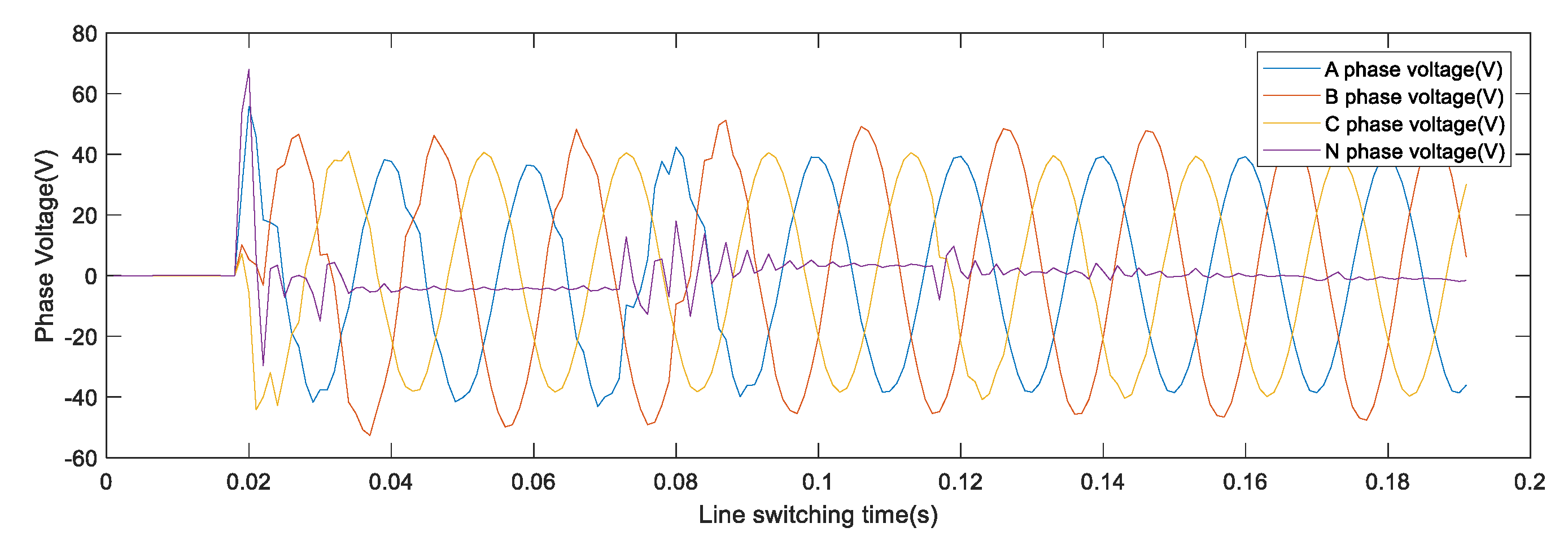
It is obvious that phase A, B, C and N voltages gradually appeared, with regular oscillations occurring thousands of times, as shown in Figure 8. The line length is 90.15 Km. The PMU of a 220 kV substation on the opposite side did not detect any fluctuations and did not trigger the fault recorder on the opposite side.
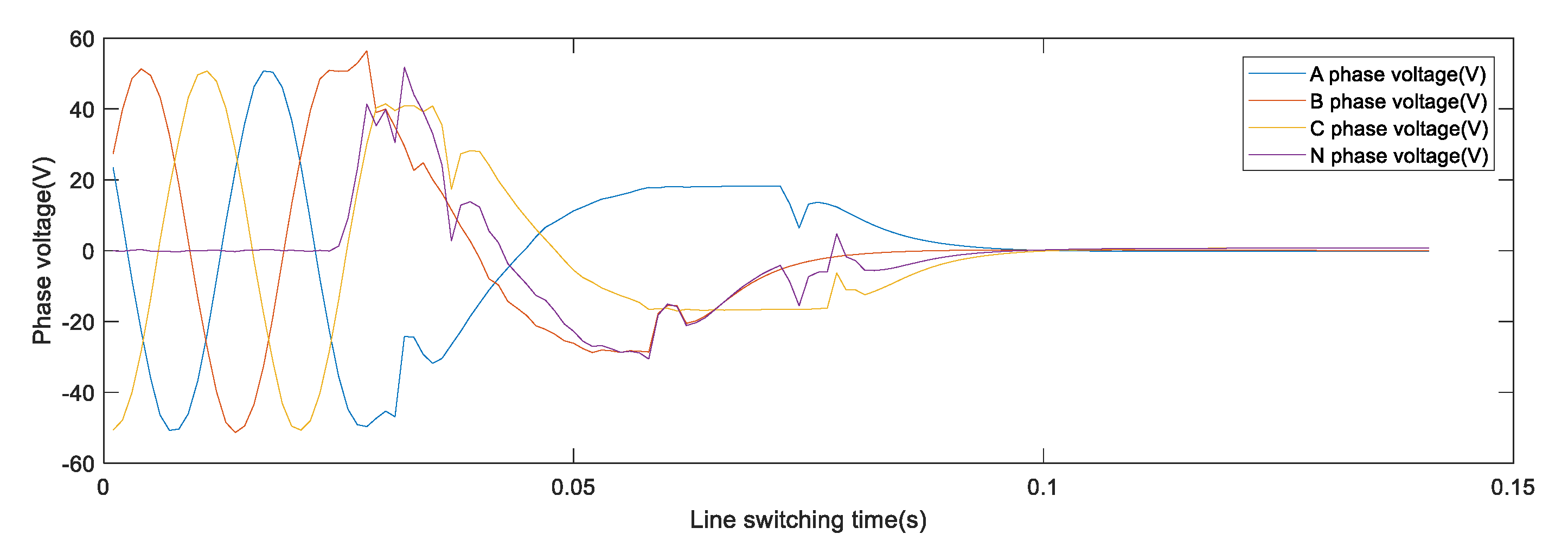
From Figure 9, when the line is cut up, it can be observed that the phase A voltage is 53.5 V, the secondary voltage distortion is obvious, the phase B voltage is 64.6 V, the secondary voltage distortion is obvious, and the phase C voltage is 54.1 V, the secondary voltage distortion is obvious at the beginning, and it shows a perfect zero wave after about 100 ms. Therefore, the reason for the voltage oscillation of the line is the A and B phase CVT, where ferro-resonance causes deviations in the measured values.
- (3)
- CVT parameter test and verification
To verify whether the equipment is damaged, the CVT site was re-checked for insulation resistance, dielectric loss, and capacitance, according to the preventive test procedure. The insulation resistance test in the previous section is mainly for the overall insulation resistance, after the high-voltage capacitors C11 and C12 are connected in series. The next section of the insulation resistance test is mainly for the insulation resistance of the medium-voltage capacitor C2; the insulation resistance N-terminal test is mainly for the insulation resistance of the last screen of the medium-voltage capacitor C2 to the ground. The test results show that they are all greater than 100 MΩ. The dielectric loss and capacitance test mainly concentrate the dielectric loss and capacitance of the high-voltage capacitors C11 and C12, and the medium-voltage capacitor C2. The test results are shown in Table 2 and Table 3. No abnormality was found, meeting the IEC 61869-5:2011 “Instrument Transformers—Part 5: Additional requirements for capacitor voltage transformers” and the DL/T 596-1996 “Preventive Test Procedures for Electrical Equipment”. The field test is shown in Figure 10.
The total capacitance is the sum of the series capacitance values of the high-voltage capacitors C11 and C12, and the medium-voltage capacitor C2. Through the pre-test data, the total capacitance of phase A is 5.246 nF, the total capacitance of phase B is 5.313 nF, and the total capacitance of phase C is 5.289 nF. The standard total capacitance of the nameplate is 5.618 nF, that is, after years of operation, the capacitance value of the current three-phase CVT decreased to varying degrees. There is almost no oscillation in the C phase, although the A and B phases oscillate. The capacitance value is just above the maximum and minimum. The explanation from the capacitance does not make sense.
The primary tap voltage value of the medium-voltage transformer is the phase voltage multiplied by the total capacitance, and then divided by the medium-voltage capacitance C1 value. According to the pre-test data in Table 2 and Table 3, the A phase is in Formula (10), B phase is , and C phase is , respectively.
- (4)
- Damper parameters and test
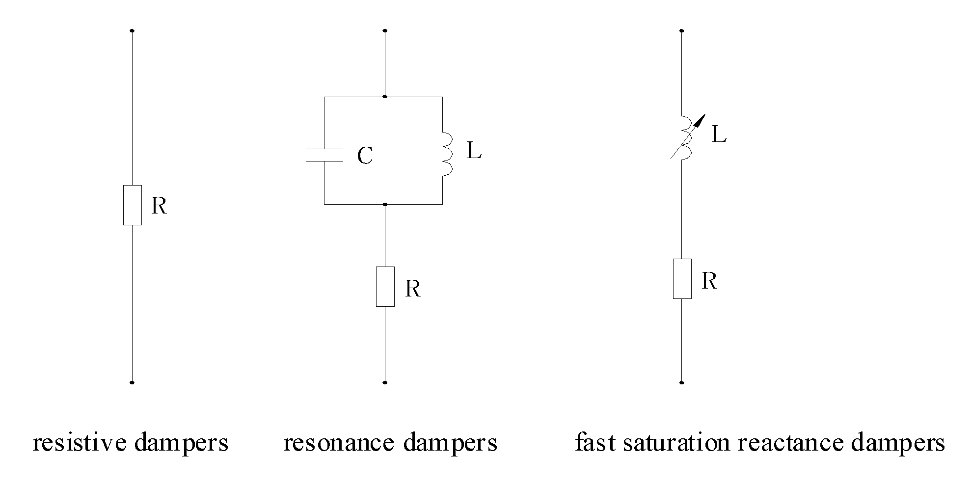
The dampers used in domestic CVT products [30] are mainly divided into the following three types: resistive dampers, resonance dampers, and fast saturation reactance dampers, as shown in Figure 11. In this case, the CVT adopts a fast saturation damper and it is connected to the da-dn winding, and the iron core is made of Permalloy. The actual product shape is shown in Figure 12.
To test the parameters of the existing CVT fast protection damper [31], the following method is used: (1) A multimeter is used to measure the resistance of the A, B, and C three-phase dampers, and the resistance values are 5.43 Ω, 5.32 Ω and 5.42Ω, respectively. (2) A 5 Ω pure resistance is connected in series with the reactance circuit, and then the reactance is measured. The current and voltage of each point are measured under the power frequency voltage. The specific voltage–current characteristics are shown in Table 4.
According to the data in Table 4, the voltage–current characteristic curve for each phase of the line can be drawn. The iron core of the existing CVT fast protection damper is made of Permalloy material [32,33]; according to the Permalloy material magnetic field intensity–magnetic induction intensity curve [34], combined with the manufacturer’s many years of manufacturing experience, it is known that the damper parameters are qualified if the index requirements in Table 5 are met. As shown in Figure 13, when the voltage exceeds 120% of the rated voltage, the phase A current increases slowly, and the three-phase current is 3.8% less than average.
According to the on-site test results, the equipment manufacturers, inspection units, and relevant personnel of the operating units comprehensively conducted the dielectric loss and capacitance tests, wiring circuit inspections, and damper inspections. They all agreed that the CVT dampers had normal characteristics and normal harmonic elimination functions.
When there is a transient equilibrium state in the CVT ferromagnetic oscillation process, if one places the data in Table 1, Table 2 and Table 3 into Formula (9), considering the safety factor, the equilibrium total impedance of the fast saturation damper is 200 Ω, but the actual impedance is less than 200 Ω; therefore, ferromagnetic oscillation occurs.
5. Discussion and Mechanism Analysis
The volt-ampere characteristics of the damper must be adjusted before assembly, to ensure the transient response characteristics of the CVT, suppress the ferromagnetic resonance performance, and facilitate the accuracy adjustment, after many years of operation. It can be observed from Figure 8 that the voltage measurement values of the winding coils 1 and 2 of the A and B phase CVTs are the same, so the possibility of coil damage is ruled out. It was initially suspected that the dampers of the A and B phases were defective, or at least that the relevant parameters of the dampers may be offset (after 17 years of operation), causing a certain line to oscillate. After discussion and analysis, the possible reasons for the A and B phase voltage fluctuations are as follows:
- (1)
- The bus voltage and other line voltages are normal during charging, indicating that system resonance does not occur, and resonance occurs inside the 220 kV line CVT. The reason for this is that the line is charging. The initial phase angle of the A and B phase voltages and the residual magnetism of the transformer just meet the resonance conditions, causing internal ferromagnetic resonance of the transformer, and voltage fluctuations. Because the damper is not in the best working condition, the inductor coil parameters deviate and cannot be improved. One must eliminate the internal ferromagnetic resonance of the transformer.
- (2)
- The 220 kV line is long. To avoid voltage that is too low at the end of the line, the CVT is designed according to the 242/√3 kV voltage level, and the configured damper parameters are also designed according to the 242/√3 kV voltage level. However, the actual line adopts a variety of methods to reduce impedance. The actual line voltage attenuation is less than 2%, that is, the line operating voltage does not reach the design value (220/√3 kV × 110%), and the damper does not operate at the rated voltage, meaning that the damper is not in the best working condition.
- (3)
- During normal operation of the line CVT, the secondary load is required to be between 25% and 100%, and the secondary load is no-load at the moment of line charging, which affects the resonance elimination effect of the damper.
In the project, which is grid-connected to prevent resonance, the preventive measures taken for this line are as follows:
- (1)
- To avoid abnormal voltage fluctuations, caused by the internal ferromagnetic resonance of the transformer during charging of the overhead line, the resistance is connected in parallel with the residual voltage winding circuit of the CVT, and one must ensure that the total impedance of the fast saturation damper is 200 Ω, and that the manufacturer has made the same type of CVT in the factory. Correlation tests can effectively suppress the internal ferromagnetic resonance of the transformer, but they will slightly affect the measurement accuracy.
- (2)
- After the charging is normal, one must cut off the residual voltage winding circuit and connect the resistance 200 Ω in parallel to prevent measurement errors, and the CVT can work normally.
6. Conclusions
This article established a CVT low-frequency equivalent model, starting from the 220 kV no-load line LC oscillation to the oscillation equilibrium state, respectively, and theoretical calculations were carried out. In this case, the first step was to suspect that the CVT equipment was damaged (such as an insulating air gap or a breakdown, etc.); therefore, two preventive tests were carried out under different temperature and humidity conditions, and the two test results proved that the dielectric damage and capacitance of the capacitor were correct. The second step, learned from the theoretical analysis, found that the damper exhibited low-frequency oscillation of the CVT functional relationship, and we suspected that there was an abnormality in the damper equipment. The actual measurements of the parameters of the fast saturation damper were carried out, according to the damper voltage–current characteristic curve, and there were no problems with the damper, but the A and B phases were not as good as the C phase characteristics. For the third step, the damping characteristics of the oscillation balance were used to obtain the formula of the maximum resistance Rz, which were 176.37 Ω, 182.12 Ω, and 184.90 Ω. For the fourth step, considering safety in engineering, the maximum capacitance was floated by 10%, and the CVT residual voltage winding circuit was connected in parallel with 200 Ω. The resistance of the line was charged again, and there was no oscillation after the grid connection, which proves that the theory in this paper is correct.
Author Contributions
Conceptualization, D.L. and K.Y.; Data curation, W.W.; Formal analysis, X.D., D.L., X.W. and J.Z.; Investigation, X.D.; Methodology, X.D. and W.W.; Validation, B.L. and J.Z. All authors have read and agreed to the published version of the manuscript.
Funding
This research was funded by the General Program of National Natural Science Foundation of China, “Research on plug-and-play integrated modular series active harmonic isolator with high reliability and cost performance” (51977089), 2020.1-2023.12.
Institutional Review Board Statement
Not applicable.
Informed Consent Statement
Not applicable.
Conflicts of Interest
The authors declare no conflict of interest.
References
- Kojovic, L.; Kezunovic, M.; Fromen, C.W. A new method for the CCVT performance analysis using field measurements, signal processing and EMTP modeling. IEEE Trans. Power Deliv. 1994, 9, 1907–1915. [Google Scholar] [CrossRef]
- Bakar, A.H.A.; Khan, S.A.; Kwang, T.C.; Rahim, N.A. A review of ferroresonance in capacitive voltage transformer. IEEJ Trans. Electr. Electron. Eng. 2015, 10, 28–35. [Google Scholar] [CrossRef]
- Ajaei, F.B.; Sanaye-Pasand, M.; Rezaei-Zare, A.; Iravani, R. Analysis and Suppression of the Coupling Capacitor Voltage Transformer Ferroresonance Phenomenon. IEEE Trans. Power Deliv. 2009, 24, 1968–1977. [Google Scholar] [CrossRef]
- Chakravarthy, S.K.; Nayar, C.V. Ferroresonant oscillations in capacitor voltage transformers. IEE Proc. Circuits Devices Syst. 1995, 142, 30–36. [Google Scholar] [CrossRef]
- Reis, R.L.D.; Neves, W.L.A.; Lopes, F.V.; Fernandes, D. Coupling Capacitor Voltage Transformers Models and Impacts on Electric Power Systems: A Review. IEEE Trans. Power Deliv. 2019, 34, 1874–1884. [Google Scholar] [CrossRef]
- Mardegan, C.S.; Melo, L.A.R.; Shipp, D.D.; Santana, M.R. The experience acquired sizing snubbers to mitigate switching transients in industrial power systems. IEEE Trans. Ind. Appl. 2015, 52, 3644–3654. [Google Scholar] [CrossRef]
- Tajdinian, M.; Allahbakhshi, M.; Biswal, S.; Malik, O.P.; Behi, D. Study of the Impact of Switching Transient Overvoltages on Ferroresonance of CCVT in Series and Shunt Compensated Power Systems. IEEE Trans. Ind. Inform. 2020, 16, 5032–5041. [Google Scholar] [CrossRef]
- Wang, Y.; Liang, X.; Pordanjani, I.R.; Cui, R.; Jafari, A.; Clark, C. Investigation of Ferroresonance Causing Sustained High Voltage at a De-Energized 138 kV Bus: A Case Study. IEEE Trans. Ind. Appl. 2019, 55, 5675–5686. [Google Scholar] [CrossRef]
- Zhao, L.; Wei, J.; Li, Q.; Xu, G.; Chen, Y.; Liu, B.; Wang, B.; Qi, Z. The influence of CVT parameters on the harmonic transmission characteristics. In Proceedings of the 2016 IEEE 11th Conference on Industrial Electronics and Applications (ICIEA), Hefei, China, 5–7 June 2016; pp. 332–337. [Google Scholar]
- Wei, C.; Li, Q.; Jiang, J. Research on harmonic transmission characteristics of capacitor voltage transformer. In Proceedings of the 2017 Progress in Electromagnetics Research Symposium—Fall (PIERS—FALL), Singapore, 19–22 November 2017; pp. 2564–2570. [Google Scholar]
- Abbasi, H.R.; Gholami, A.; Fathi, S.H.; Abbasi, A. Effect of metal oxide arrester on the chaotic oscillations in the voltage transformer with nonlinear core loss model using chaos theory. Chin. Phys. B 2014, 23, 018201. [Google Scholar] [CrossRef]
- Bin, H.; Zutao, X.; Liangeng, B.; Qiyan, M.; Weidong, L. Study on transients and effect on capacitor voltage transformer caused by disconnector switching of UHV Series Capacitor Banks. In Proceedings of the 2014 International Conference on Power System Technology, Chengdu, China, 20–22 October 2014; pp. 2293–2298. [Google Scholar]
- Chen, L. Optimization of Capacitive Voltage Transformers with Series Saturated Reactor Damper; High Voltage Apparatus: Xi’an, China, 2015; pp. 114–119. [Google Scholar]
- Sakamuri, J.; Yesuraj, D.J. Modeling and Simulation of Capacitor Voltage Transformer Transients using PSCAD/EMTDC, Trondheim. In Proceedings of the 2011 IEEE Trondheim PowerTech, Trondheim, Norway, 19–23 June 2011; pp. 1–8. [Google Scholar]
- Tziouvaras, D.A.; McLaren, P.; Alexander, G.; Dawson, D.; Esztergalyos, J.; Fromen, C.; Glinkowski, M.; Hasenwinkle, I.; Kezunovic, M.; Kojovic, L.; et al. Mathematical Models for Current, Voltage, and Coupling Capacitor Voltage Transformers. IEEE Trans. Power Deliv. 2000, 15, 62–72. [Google Scholar] [CrossRef]
- Jacobson, D.A.N.; Lehn, P.W.; Menzies, R.W. Stability Domain Calculations of Period-1 Ferroresonance in a Nonlinear Resonant Circuit. IEEE Trans. Power Deliv. 2002, 17, 865–871. [Google Scholar] [CrossRef]
- Beres, R.N.; Wang, X.; Blaabjerg, F.; Liserre, M.; Bak, C.L. Optimal Design of High-Order Passive-Damped Filters for Grid-Connected Applications. IEEE Trans. Power Electron. 2016, 31, 2083–2098. [Google Scholar] [CrossRef] [Green Version]
- Aghazadeh, R.; Sanaye-Pasand, M. Damping of capacitive voltage substations ferroresonance using a suitable RLC filter. IEE Proc. Gener. Transm. Distrib. 2004, 151, 721. [Google Scholar] [CrossRef]
- Lyu, D.; Sun, Y.; Li, Y.; Zhao, J.; Ji, Z.; Li, D. Transient Oscillation Suppression Method of Modular Multilevel DC Transformer. IEEE Access 2020, 8, 182943–182958. [Google Scholar] [CrossRef]
- Zare, M.H.; Mirzaei, A.; Abyaneh, H.A. Designing a compensating electronic circuit to enhance capacitive voltage transformer characteristics. In Proceedings of the 9th Power Systems Protection and Control Conference (PSPC2015), Tehran, Iran, 14–15 January 2015; pp. 12–18. [Google Scholar]
- Sakamuri, J.N.; Yesuraj, D.J.; Joshi, S.R. Simulation and Testing of Novel Ferro-Transient Suppression Circuit for CVT. In Proceedings of the 2015 IEEE Power & Energy Society General Meeting, Denver, CO, USA, 26–30 July 2015. [Google Scholar]
- Wang, D.; Wang, X.A. Study of the protective device with inductor in series resistance for capacitor voltage transformer. Trans. China Electrotech. Soc. 2000, 22, 41–46. [Google Scholar]
- Huang, S.; Liu, S.; Hsien, T.; Lee, S.; Cheng, C.; Fan, C. Effect of CCVT Gap Protection Circuit on Voltage Distortion. IEEE Trans. Power Deliv. 2008, 23, 686–692. [Google Scholar] [CrossRef]
- Ming, X.; Houlei, G.; Guanghong, Y.; Ronghua, Y.; Guibin, Z. A Novel correcting method for transient errors of CVT. In Proceedings of the 10th IET International Conference on Developments in Power System Protection (DPSP 2010)—Managing the Change, Manchester, UK, 29 March–1 April 2010; pp. 1–5. [Google Scholar]
- Zhang, J.; Li, B.; Tang, B.; Yang, J.; Huang, L. Resistor-Capacitor Combined DC Bias Protection of AC Power Grid of Jiuquan-Hunan ±800 kV Transmission Lines. IEEE Access 2019, 7, 38730–38737. [Google Scholar] [CrossRef]
- Meng, P.; Chen, H.; Zheng, S.; Wu, X.; Qian, Z. Optimal design for the damping resistor in RCD-R snubber to suppress common-mode noise. In Proceedings of the 2010 Twenty-Fifth Annual IEEE Applied Power Electronics Conference and Exposition (APEC), Palm Springs, CA, USA, 21–25 February 2010; pp. 691–695. [Google Scholar]
- Zhou, Z.; Cai, C.; Zhu, H.; Yang, X.; Wu, F.; Liu, H. Test and diagnosis on a secondary voltage loss fault of a 220kV capacitor voltage transformer. In Proceedings of the 2016 IEEE International Conference on High Voltage Engineering and Application (ICHVE), Chengdu, China, 19–22 September 2016; pp. 1–4. [Google Scholar]
- Machado, E.P.; Fernandes, D.; Neves, W.L.A. Tuning CCVT Frequency Response Data for Improvement of Numerical Distance Protection. IEEE Trans. Power Deliv. 2018, 33, 1062–1070. [Google Scholar] [CrossRef]
- Shahabi, S.; Mirzaei, M.; Gholami, A.; Taheri, S. Investigation of performance of ferroresonance suppressing circuits in coupling capacitor voltage transformers. In Proceedings of the 4th IEEE Conference on Industrial Electronics and Applications, Kuala Lumpur, Malaysia, 3–4 October 2009; pp. 216–221. [Google Scholar]
- Mohan, V.; Poornima, S.; Sugumaran, C.P. Mitigation of Ferroresonance in Capacitive Voltage Transformer Using Memelements. In Proceedings of the International Conference on High Voltage Engineering and Technology (ICHVET), Hyderabad, India, 7–8 February 2019; pp. 1–5. [Google Scholar]
- Roy, M.; Roy, C.K. Experiments on Ferroresonance at Various Line Conditions and Its Damping. In Proceedings of the 2008 Joint International Conference on Power System Technology and IEEE Power India Conference, New Delhi, India, 12–15 October 2008; pp. 1–8. [Google Scholar]
- Rezaei-Zare, A.; Iravani, R.; Sanaye-Pasand, M. Impacts of Transformer Core Hysteresis Formation on Stability Domain of Ferroresonance Modes. IEEE Trans. Power Deliv. 2009, 24, 177–186. [Google Scholar] [CrossRef]
- Rezaei-Zare, A.; Sanaye-Pasand, M.; Mohseni, H.; Farhangi, S.; Iravani, R. Analysis of Ferroresonance Modes in Power Transformers Using Preisach-Type Hysteretic Magnetizing Inductance. IEEE Trans. Power Deliv. 2007, 22, 919–929. [Google Scholar] [CrossRef]
- Rezaei-Zare, A.; Iravani, R.; Sanaye-Pasand, M.; Mohseni, H.; Farhangi, S. An Accurate Hysteresis Model for Ferroresonance Analysis of a Transformer. IEEE Trans. Power Deliv. 2008, 23, 1448–1456. [Google Scholar] [CrossRef]
Figure 1.
Equivalent schematic diagram of CVT.

Figure 2.
Simplified equivalent schematic diagram of CVT.

Figure 3.
Saturable transformer model in Simulink.

Figure 4.
Simulink simulation of the CVT secondary side waveform.

Figure 5.
Simulink simulation of the CVT secondary side frequency spectrum.

Figure 6.
Time-domain waveform of the single-phase waves.

Figure 7.
Frequency spectrum of the single-phase waves.

Figure 8.
Transient voltage fluctuation of A, B, C, and N in line disconnected.

Figure 9.
Transient voltage fluctuation of A, B, C, and N in line cut.

Figure 10.
Field test.

Figure 11.
Type of damper.

Figure 12.
Fast saturation damper.

Figure 13.
V-I characteristic curve of fast saturation damper.


Table 1.
Nameplate parameters of CVT.
| Model | TYD242/√3 − 0.005 H |
|---|---|
| Rated Voltage | 242 kV |
| Frequency | 50 Hz |
| Capacity Protection, Control, Measurement Capacity | 0.005618 uF 25 VA |
Table 2.
Insulation resistance test results.
| Test Place | A/GΩ | B/GΩ | C/GΩ |
|---|---|---|---|
| Previous | |||
| (high-voltage capacitor) | 1.73 | 1.32 | 1.64 |
| Next | |||
| (medium-voltage capacitor) | 1.73 | 1.32 | 1.64 |
| N | 2.17 | 2.20 | 6.45 |
Table 3.
Dielectric loss and capacitance test results.
| Test Capacitor | Tanδ% | Cx/nF | CN/nF | ΔC/% | |
|---|---|---|---|---|---|
| A | C11 | 0.123 | 10.52 | 10.51 | +0.10 |
| C12 | 0.126 | 12.99 | 12.98 | +0.08 | |
| C2 | 0.139 | 54.08 | 54.03 | +0.09 | |
| B | C11 | 0.134 | 10.65 | 10.64 | +0.09 |
| C12 | 0.132 | 13.10 | 13.09 | +0.08 | |
| C2 | 0.141 | 55.99 | 55.88 | +0.20 | |
| C | C11 | 0.105 | 10.54 | 10.53 | +0.09 |
| C12 | 0.091 | 13.08 | 13.07 | +0.08 | |
| C2 | 0.118 | 56.05 | 55.99 | +0.11 | |
Table 4.
Dielectric loss and capacitance test results.
| U/V | Phase A | Phase B | Phase C | |||
|---|---|---|---|---|---|---|
| I/A | R/Ω | I/A | R/Ω | I/A | R/Ω | |
| DC10 | 0.96 | 5.43 | 0.97 | 5.32 | 0.96 | 5.42 |
| AC100 | 0.00 | — | 0.00 | — | 0.00 | — |
| AC120 | 0.03 | — | 0.03 | — | 0.03 | — |
| AC122 | 0.05 | — | 0.06 | — | 0.07 | — |
| AC124 | 0.21 | — | 0.23 | — | 0.27 | — |
| AC130 | 2.18 | — | 2.52 | — | 2.57 | — |
| AC150 | 7.11 | — | 7.42 | — | 7.65 | — |
Table 5.
The qualified standard for voltage–current characteristics of dampers.
| Voltage (V) | 120 | 122~124 | 150 |
|---|---|---|---|
| Current(A) | <0.1 | 0.2 occur | >5 |
Publisher’s Note: MDPI stays neutral with regard to jurisdictional claims in published maps and institutional affiliations. |
© 2022 by the authors. Licensee MDPI, Basel, Switzerland. This article is an open access article distributed under the terms and conditions of the Creative Commons Attribution (CC BY) license (https://creativecommons.org/licenses/by/4.0/).
Share and Cite
MDPI and ACS Style
Ding, X.; Yang, K.; Wang, W.; Liu, B.; Wang, X.; Zhang, J.; Li, D. Ferro-Resonance Analysis of Capacitor Voltage Transformer with Fast Saturation Damper. Energies 2022, 15, 2791. https://0-doi-org.brum.beds.ac.uk/10.3390/en15082791
AMA Style
Ding X, Yang K, Wang W, Liu B, Wang X, Zhang J, Li D. Ferro-Resonance Analysis of Capacitor Voltage Transformer with Fast Saturation Damper. Energies. 2022; 15(8):2791. https://0-doi-org.brum.beds.ac.uk/10.3390/en15082791
Chicago/Turabian StyleDing, Xinzhi, Kai Yang, Weiyu Wang, Bin Liu, Xuejin Wang, Jie Zhang, and Dayi Li. 2022. "Ferro-Resonance Analysis of Capacitor Voltage Transformer with Fast Saturation Damper" Energies 15, no. 8: 2791. https://0-doi-org.brum.beds.ac.uk/10.3390/en15082791
Note that from the first issue of 2016, this journal uses article numbers instead of page numbers. See further details here.