Article

Particle Swarm Optimization Based Optimal Design of Six-Phase Induction Motor for Electric Propulsion of Submarines

1
Department of Electrical and Computer Engineering, Bule Hora University, Bule Hora P.O. Box 144, Ethiopia
2
Faculty of Electrical and Computer Engineering, Jimma Institute of Technology, Jimma University, Jimma P.O. Box 378, Ethiopia
3
Faculty of Electrical and Control Engineering, Gdańsk University of Technology, Gabriela Narutowicza 11/12, 80-233 Gdańsk, Poland
4
Department of Electrical Engineering, College of Engineering, Princess Nourah bint Abdulrahman University, P.O. Box 84428, Riyadh 11671, Saudi Arabia
*
Author to whom correspondence should be addressed.
Submission received: 11 March 2022 / Revised: 7 April 2022 / Accepted: 12 April 2022 / Published: 20 April 2022
(This article belongs to the Special Issue Control, Operation and Protection of Multiphase Machines and Drives)

Abstract

:
Recent research reveals that multi-phase motors in electric propulsion systems are highly recommended due to their improved reliability and efficiency over traditional three phase motors. This research presented a comparison of optimal model design of a six phase squirrel cage induction motor (IM) for electric propulsion by using Genetic Algorithm (GA) and Particle Swarm Optimization (PSO). A six phase squirrel cage induction motor is designed and simulated by ANSYS Motor-CAD. In order to find the best fit method, simulation results are compared and applied to the motors for electric propulsion, considering the influence of design upon the motor performance. The six-phase squirrel cage induction motor is more energy efficient, reliable and cost effective for the electric propulsion compared to the conventional three phase motor. In this study, first the initial parameters of the six phase squirrel cage induction motor have been determined and then these parameters have been compared with optimized values by Genetic Algorithm (GA) and PSO optimization. The motor designed is optimized using efficiency and power losses as the fitness function. The six phase squirrel cage induction motor is designed using ANSYS Motor-CAD and the simulation results were also presented along with two-dimensional and three-dimensional geometry. The result shows that the weight and power loss are reduced to 161 kg and 0.9359 Kw respectively, while the efficiency and power factor are increased to 0.95 and 0.87 respectively when PSO is used. This shows that the result is promising.

1. Introduction

Modern submarines are complex types of machines that exist today, revolutionizing the marines and with the presence of multi phase motors witnessing burst in their daily performance, intended for underwater research, maintenance, or military purposes. The intentions of military submarines are attacking enemy surface ships or submarines and also serving as portable missile launchers, and their subtle nature makes them suitable for surveillance and the deployment of special forces in enemy territory, and so forth. All these make submarines very popular for the military power of developed countries [1]. A six phase induction machine is a dual stator winding induction motor with two sets of three phase currents and is visualized as a dual stator winding induction motor, as with paralleling two three phase induction motors. A single dual stator winding induction motor can replace the two three phases and cost is decreased while reliability is enhanced [2].
Different types of AC motor are used for electric propulsion. In this research, a six-phase squirrel cage induction motor has been proposed because of design simplicity, robustness and is less expensive than a similarly rated Permanent Magnet Synchronous Motor. The six-phase squirrel cage induction motor is approximately 15% less expensive than the Six Phase Permanent Magnet Synchronous Motor. They are the most applicable electric machines to industry, transportation system and other applications due to their higher torque and low maintenance compared to other rotating electrical machines. These advantages contribute to their reliability and make them attractive for electric propulsion applications. Three phase induction motors have been used for transportation and industrial application even though they have a setback with respect to performance especially in the case of phase loss [3,4]. A major problem referring to the machine model is the limitation to three-phase losses [5]. In the case of a three phase induction motor, phase loss happens, the motor does not produce an adequate performance such as output power and torque, as is required for electric propulsion applications and hazardous environments such as mining, pumping and blowing operations [6,7]. To reduce the phase loss problem, the six phase induction motor gained more attention due to its simplicity in converting the three phase to six phase [8]. The six phase induction motor has a three phase induction motor that has dual stator winding shifted by 30 electrical degrees. This is the solution to the three phase induction motor phase loss problem [9]. The system reliability improves when the six phase induction motor is used. As a result, the harmonic current in the rotor is also minimized. The six phase induction motor is used for traction applications and is employed in electric propulsion systems (ships and aircraft) [10]. Due to the high degree of reliability, demands in electric aircrafts, electric submarines propulsion, electric vehicles, and so forth are the application area of multiphase induction motors [11]. Due to the ease of operation, high reliability, cost effectiveness, easy maintenance and low noise compared to other motors, six phase induction motors are widely applied in industries in recent years [12].
The Genetic Algorithm (GA) has been used to optimize the design of electrical machines. During optimization, GA undertakes design variable selection, crossover, and mutation. The advantage of GA over traditional nonlinear programming techniques is that it can find the global minimum than the local minimum [13]. Induction motor (IM) design difficulties are also solved by GA. However, these strategies do not always yield the globally optimal solution; in some cases, they may provide poor results. One of the modern evolutionary algorithms is the PSO algorithm. PSO is a population based method that is conceptually straightforward to implement, and highly efficient. PSO is an optimization technique that can be utilized to solve many of the same problems as GA while avoiding some of GA’s drawbacks. Particle Swarm Optimization has also been demonstrated to be reliable in the case of non linearity and high dimensional challenges [14]. Nowadays, the optimum design of six phase induction motors has gained greater attention [15]. This research paper presented a novel method of multi objective design and the optimization of six phase induction motors. The proposed method is more efficient than the traditional design method because of high performance and reliability. The particle swarm optimization (PSO) algorithm has been compared to manual design in this research paper with the main goal of finding which is more suitable for the design of six phase induction motors. The research presents an optimal design of six phase induction motors for obtaining optimal size and efficiency. For this purpose, PSO is applied and it has not been used for the optimum design of such motors yet. Optimization is performed with an objective function, which is a combination of maximum efficiency and minimum size. This approach is used to design a six-phase IM, and the results were compared to the GA and the traditional design method.

2. Proposed System Design

The tools that we used for these studies were Ansys Motor-CAD and MATLAB Software. Ansys Motor-CAD was used to evaluate motor topologies and concepts across the full operating range [16,
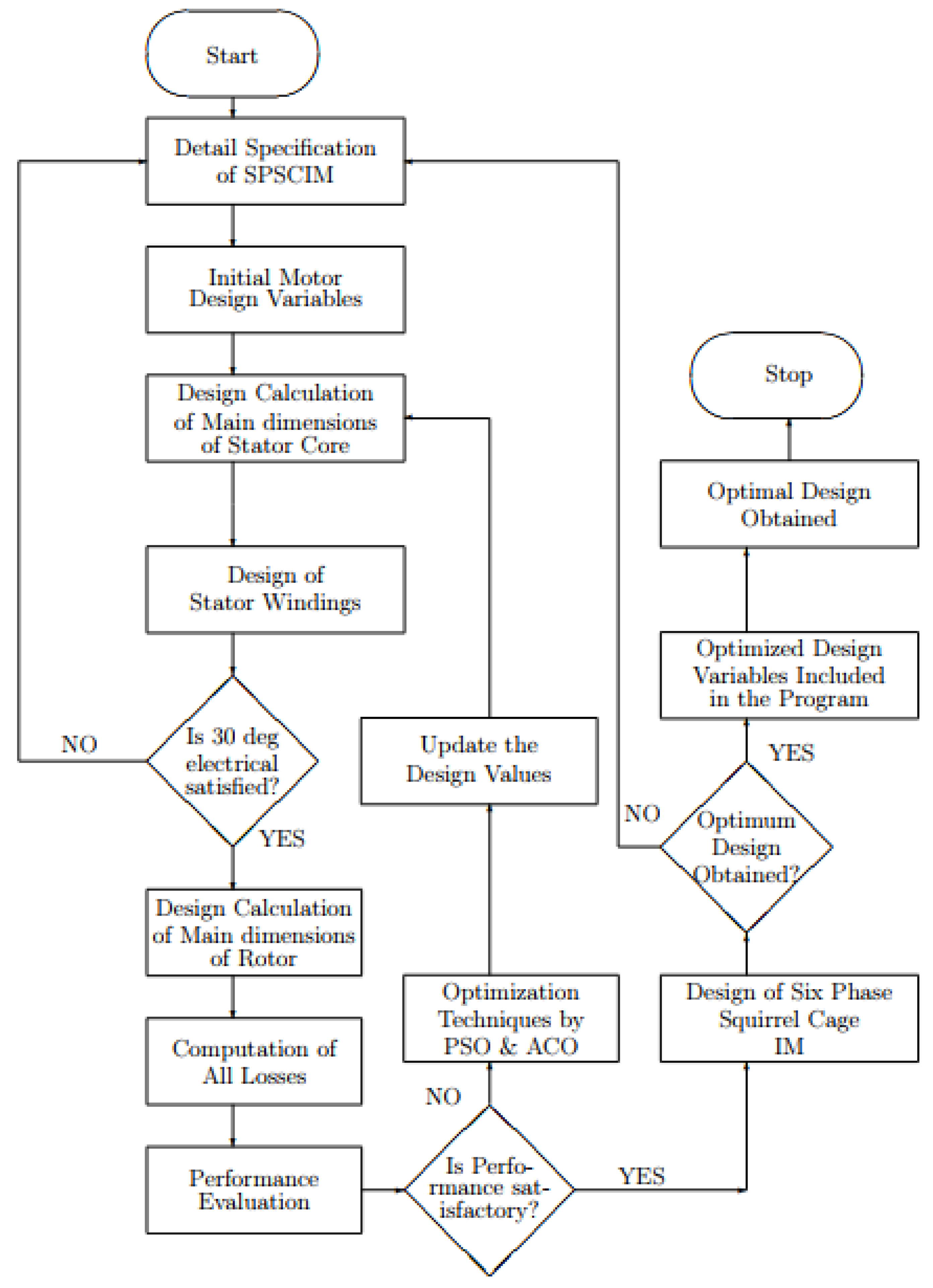
17]. MATLAB software was used throughout the whole code development process, such as writing, compiling, debugging, and programming for the Genetic Algorithm and the PSO algorithm. The MATLAB program for the PSO application is written and executed. In terms of the given design variables to be optimized, this software minimizes stator copper loss, rotor copper loss, and stator iron loss. The efficiency, weight and power factors have been optimized, and the optimized values have been put into the main program for the best design possible. As a result, the parameters of a six phase induction motor have been assessed, and the values have been verified. The total losses in the stator and rotor are used as objective functions to be minimized since the design optimization of a six-phase induction motor requires objective functions affecting performance aspects. The PSO optimized six-phase induction motor design process is depicted in Figure 1, which includes current density, flux density, magnetic and electric loading; aspect ratio and other factors are chosen based on the motor’s detailed specifications. The design is prepared with the assumption of efficiency and power factor. The acquired result is examined to see if the assumptions are correct. If this is not the case, the process is repeated.
One of the most essential parts of electrical machine design is optimizing optimization. The problem of optimizing six phase induction motor design is represented mathematically as a non-linear programming. The total power loss equation is minimized to obtain optimal efficiency [18]. The Particle Swarm Optimization method is made up of a group of particles that move throughout the search space based on their own best previous position as well as the best past location of the entire swarm or a near neighbor [19]. Similar to the genetic algorithm and the evolution algorithm, PSO is also a computation technique inspired by a flock of birds or a school of fish. In this case, the particle (bird or fish) searches for its neighbors, comparing itself to other populations and follows the superior neighbors [20].
The velocity of a particle is adjusted in each iteration by:
V i ( t + 1 ) = V i ( t ) + C 1 r a n d ( ) ( p i b e s t p i ( t ) ) + C 2 r a n d ( ) ( p g b e s t p i ( t ) ) ,
where V i ( t + 1 ) is the ith particle velocity, C 1 and C 2 are personal best and global best weighting coefficients, respectively, p i ( t ) is the ith particle’s position at time t, p i b e s t is the ith particle’s best known position, and p g b e s t is the best position known to the swarm. A particle’s position is updated using:
p i ( t + 1 ) = p i ( t ) + v i ( t ) .
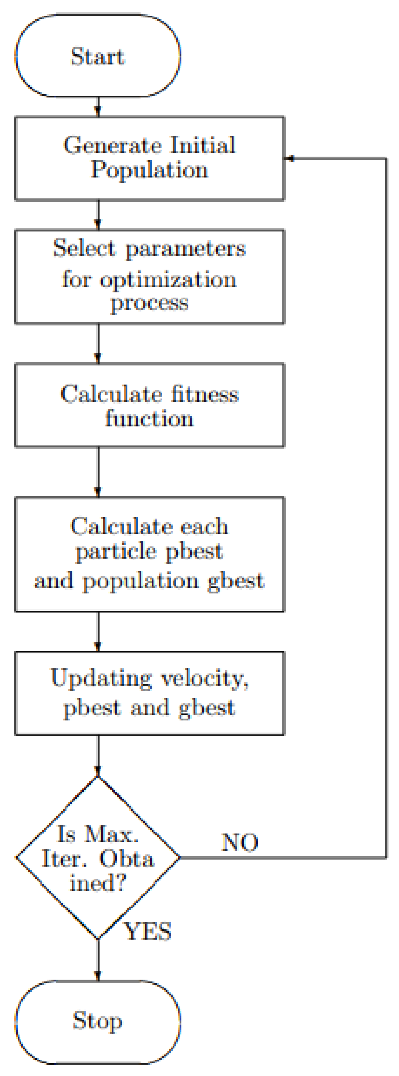
Figure 2 shows a particle swarm optimization algorithm flowchart.
A standard PSO suffers a convergence prematurely and is easily trapped at a local optimum due to loss of population diversity. To avoid this problem, a balance between global and local search abilities can be taken into consideration and inertial weight PSO was proposed. The velocity of a inertial weight PSO is updated in each iteration by:
V i ( t + 1 ) = ω ( i ) V i ( t ) + c 1 r 1 ( p i b e s t x i ( t ) ) + c 2 r 2 ( g i b e s t x i ( t ) )
ω i = ω ( i n i t ) ( ω ( i n i t ) ω ( e n d ) ) t T ( i t e r a t i o n ) .
Still, when inertial weight is small, the algorithm comes back to the problem of exploitation at the local optimum for gbest and pbest. To deal with premature convergence, a Self Regulated PSO is proposed which provides a better exploitation and exploration to the standard PSO. In this self regulated PSO, the best particle will have the higher acceleration process by making an increased initial weight. Velocity is updated as follows:
V i ( t + 1 ) = ω ( i ) V i ( t ) + c 1 r 1 p s e ( p i b e s t x i ( t ) ) + c 2 r 2 p s o ( g i b e s t x i ( t ) ) ,
where ω ( i ) is the ith particle inertial weight, p s e is self cognition perception and p s o is social cognition perception; p s e and p s o are zero for best particle and one for non best particle. Generally, particle swarm optimization is used to optimize the loss of the induction motor through writing Matlab code on Matlab software by using an objective function and derived total power loss of the motor.

2.1. Optimization Function Problem Formulation

The key to optimizing the six-phase induction motor design is to select independent variables; otherwise optimization is complicated if many variables are used. As a result, variable selection is critical for optimizing motor designs. The following is a mathematical representation of a general nonlinear programming problem.
Find X = g ( x 1 ; x 2 : : : : : x n ) such that g i ( x ) is a minimum or maximum, b i ( x ) ≤ 0, i = 1, 2, ..., n; g i ’s are objective function to be minimized or maximized and b i are constants and x i ’s are the variables.
Finally, the total power equation is derived and then the derived equation was converted into the MATLAB program. Then by using PSO and GA algorithms, the derived equation was programmed and the program was executed on the MATLAB software. Then, simulation of the model was performed by using ANSYS Motor-CAD and the simulation result was verified.

2.2. Derivation of Objective Function

The six phase IM losses were used as an objective function. There are two main losses considered in the six-phase induction motor. These are Copper Loss (Stator Copper Loss and Rotor Copper Loss) and Stator Iron Loss. The major losses that are found in the parts of induction motor are iron losses. The two types of iron losses are hysteresis and eddy current losses. The copper loss occurs due to the current flowing through the winding resistance of the motor. So these losses can be minimized by reducing resistance of winding, increasing the conductor’s cross sectional area, lowering the temperature of winding and using lower resistivity materials Author1 [21].
Most of the time, extra losses can be reduced by using copper conductor materials with increased current densities. The causes of hysteresis loss are related to electrical frequency and that of eddy current loss is related to the square of the electrical frequency. The performances of six phase induction motors are affected by stator and rotor losses. To apply the PSO, the first objective function is defined to evaluate six phase squirrel cage IM design to obtain an overall good performance. The first objective function aims to minimize the total losses. Let us derive its mathematical equation with each loss for clarity.

2.2.1. Stator Copper Loss

Stator Copper Loss ( P s t ) is determined as follows
P s t = 6 I s 2 R s .
However, the resistance is given by:
R = ( ρ l ) / a .
In addition, rewriting the resistance formula for stator copper winding, we have:
R s = ρ c u l m t N p h a c u .
Current density is given as follows:
J s = I s a c u .
Substituting Equation (9) into Equation (8), we have:
R s = ρ c u l m t N p h J s I s .
Now, substituting Equation (10) into Equation (6), we have the following:
P s t = 6 ρ c u l m t N p h J s I s 2 I s .
By simplifying Equation (11) we have:
P s t = 6 ρ c u l m t N p h J s .

2.2.2. Rotor Copper Loss

Rotor Copper Loss ( P r t ) is the sum of the rotor bar loss and the rotor end ring loss.
P r t = Rotor bar loss ( P b ) + End ring loss ( P e ) Rotor bar loss ( P b ) is found as follows
P b = I b 2 R b S r .
However,
R b = ρ c u l b a b
We also have:
a b = I b J b .
Substituting Equation (15) into Equation (14), we have:
R b = ρ c u l b J b I b .
Now substituting Equation (16) into Equation (13), we have the following:
P b = I b 2 ρ c u l b J b S r I b .
By simplifying Equation (17) we have:
P b = ρ c u l b J b S r I b .
End ring loss ( P e ) can be determined as follows:
P e = 2 I e 2 R e .
However,
R e = ρ c u l e a e ,
where l e = mean length of current path in the end ring = circumference of end ring.
l e = π D e .
Substituting Equations (20) and (21) into Equation (19) we have the following equation:
P e = 2 I e 2 ρ c u π D e a e R e .
In addition, we have:
a e = I e J e .
Substituting Equation (23) into Equation (22), we have:
P e = 2 π ρ c u J e I e D e .
Therefore, rotor copper loss becomes:
P r t = P b + P e
P r t = P b + P e
P r t = ρ c u l b J b S r I b + 2 π ρ c u J e I e D e .
Now, total copper loss is found by adding all copper losses.
P c u = P s t + P r t
P c u = 6 ρ c u l m t N p h I s J s + ρ c u l b J b S r I b + 2 π ρ c u J e I e D e .
Equation (29) shows six phase induction motor copper losses.

2.2.3. Stator Iron Loss

Stator iron loss ( P f e ) can be determined as follows:
P f e = ρ f e ( V t K 1 f K 2 B s t K 3 + V c K 1 f K 2 B s c K 3 ) ,
where V t = Volume of teeth; V c = Volume of core.
V t = w s t d s s l s s
V c = ( π l ) 4 ( D o 2 [ D + 2 d s s ] 2 ) .
However, we have the following relationship:
D o = D + 2 d s s + 2 d s c .
By rearranging Equation (33), we have the following:
D o 2 d s c = D + 2 d s s .
Now substituting Equation (34) into Equation (32), we have:
V c = ( π l ) 4 ( D o 2 [ D o 2 d s c ] 2 ) .
By squaring the terms inside the brackets and simplifying Equation (35), we obtain
V c = ( π l ) 4 ( D o 2 [ D o 2 4 D o d s c + 4 d s c 2 ] )
V c = ( π l ) 4 ( D o 2 D o 2 + 4 D o d s c 4 d s c 2 ] )
V c = π l ( D o d s c d s c 2 ] )
V c = π l d s c ( D o d s c ) .
Substituting Equation (33) into Equation (39), we have:
V c = π l d s c ( D + 2 d s s + d s c ) .
Finally substituting Equations (31) and (40) into the expression of stator iron loss in Equation (30), we have:
P f e = ρ f e ( w s t d s s l s s K 1 f K 2 B s t K 3 + π l d s c ( D + 2 d s s + d s c ) K 1 f K 2 B s c K 3 ) ) .
Therefore, total losses of the six-phase induction motor are determined as follows: (P) = Total Copper Loss ( ρ c u ) + Total Iron Loss ( ρ f e )
P t = 6 ρ c u l m t N p h J s + ρ c u l b J b S r I b + 2 π ρ c u J e I e D e + ρ f e ( w s t d s s l s s K 1 f K 2 B s t K 3 + π l d s c ( D + 2 d s s + d s c ) K 1 f K 2 B s c K 3 ) .

2.3. Weight Determination

To apply the particle swarm optimization technique, a weight objective function has to be defined to evaluate how good each motor design is, especially related to weight. The objective functions are related to weight minimization. The mathematical expression of the weight of material, of the six phase squirrel cage induction motor is similar to that of a 3P induction motor in their form except their weight may differ because the stator winding is different. The weight of iron used for stator diameter is determined as follows:
W i s d = ρ f e L ( π 4 ( D o 2 ( D o 2 d s c ) 2 ) ) .
where
W i s d = weight of iron of stator diameter,
ρ f e = Iron Resistivity,
L = Stator Length,
D o = Stator Diameter,
d s c = Stator Core Diameter.
The weight of iron used for stator bore diameter is determined as follows.
W i s b d = ρ f e L ( π 4 ( D 2 ( D 2 d s c ) 2 ) ) ,
where
W i s b d = weight of iron of stator bore diameter and
D = the bore diameter of stator,
The weight of iron used for stator teeth is determined as follows:
W i s t = ρ f e L ( S s w s t d s s ) ,
where
W i s t = weight of iron of stator teeth,
S s = number of stator slot,
W s t = width of stator teeth and
d s s = diameter of rotor slot.
The weight of iron used for rotor teeth is determined as follows:
W i r t = ρ f e L ( S r w r t d r s ) ,
where
W i r t = weight of iron of rotor teeth,
S r = number of rotor slot,
w r t = width of rotor teeth and
d r s = diameter of rotor slot.
Total iron weight Wit is determined by the following formula:
W i t = W i s d + W i s b d + W i s t + W i r t
W i t = ρ f e L ( π 4 ( D o 2 ( D o 2 d s c ) 2 ) + ρ f e L ( π 4 ( D 2 ( D 2 d s c ) 2 ) + ρ f e L ( S s w s t d s s ) + ρ f e L ( S r w r t d r s )
W i t = ρ f e L ( ( π 4 ( D o 2 ( D o 2 d s c ) 2 ) + π 4 ( D 2 ( D 2 d s c ) 2 ) + ( S s w s t d s s ) + ( S s w r t d r s ) ) .
The copper weight includes stator winding weight, weights of rotor bars and two end-rings. The weight of copper used for stator winding is determined as follows:
W s w c = p c u N p h l m t a c u .
where
W s w c = weight of stator winding copper,
p c u = the resistivity of copper,
N p h = number of turns per slot per phase,
l m t = mean turn length and
a c u = the area of stator winding of stator.
The weight of copper used for rotor bars is determined as follows:
W r b c = ρ c u ( S r A b a r ( L + l b a r ) ) ,
where
W r b c = weight of rotor bar copper,
S r = number of rotor slot,
A b a r = Rotor bar cross sectional area and
l b a r = Rotor bar length.
The weight of copper used for two end rings are determined as follows:
W e r c = ρ c u ( 2 A e π D e ) ,
where
W e r c = weight of end rotor copper,
A e = area of end ring of rotor and
D e = Rotor end-ring diameter.
The total weight of copper materials W c t used is determined as follows:
W c t = W s w c + W r b c + W e r c
W c t = ρ c u N p h l m t a c u + ρ c u ( S r A b a r ( L + l b a r ) ) + ρ c u ( 2 A e π D e ) .
Therefore total iron and copper weight material W t is obtained as follows:
W t = W i t + W c t
W t = ρ f e L ( π 4 ( D o 2 ( D o 2 d s c ) 2 ) + ρ f e L ( π 4 ( D 2 ( D 2 d s c ) 2 ) + ρ f e L ( S s w s t d s s ) + ρ f e L ( S r w r t d r s ) + ρ c u N p h l m t a c u + p c u ( S r A b a r ( L + l b a r ) ) + ρ c u ( 2 A e π D e ) .

2.4. ANSYS Motor CAD

An overview of ANSYS Motor-CAD can be found at this link (https://www.motor-design.com/wp-content/uploads/About-Ansys-Motor-CAD-Brochure.pdf (accessed on 9 November 2021)).
Then the software was launched and the information about the motor to be designed was entered. Manual modeling was used to determine the value of those data. The software created a model of the stator core, stator slot, stator winding, rotor core, rotor slot, and the model when the rotor was inserted in the stator using the input parameters. In the following diagrams, those models are described one by one. 
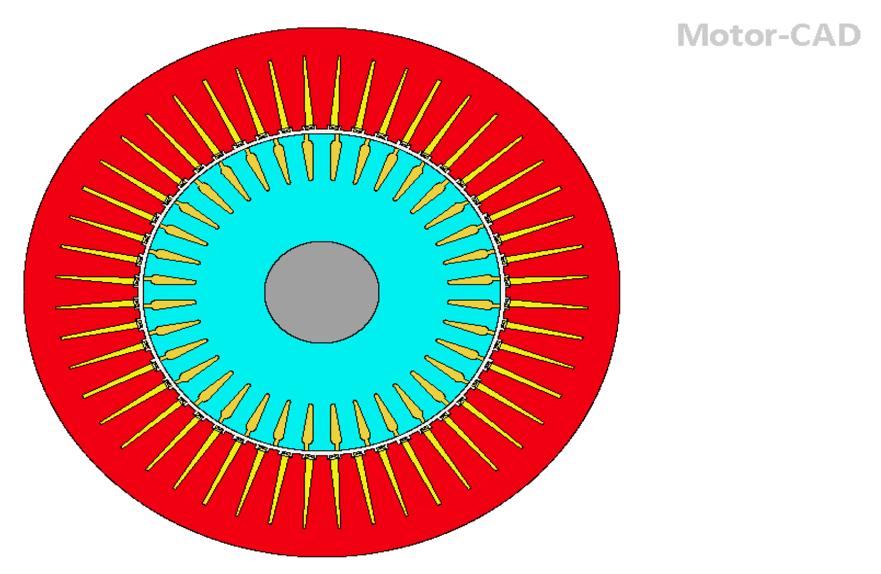
Figure 3 shows a representation of the stator core and rotor core. The stator core is the outer stationary portion of an induction motor. M19 29 Gauge steel material was used to model this stator core, which has minimal core loss, excellent permeability at low and moderate inductions, and outstanding stamping properties. The rotor core is built of the same steel as the stator core [22]. It has thirty-eight slots that are ready for rotor bar casting. When the rotor core was put into the stator core with a sufficient air gap between them, as shown below. First, a machine model was created. This machine’s data were known from previous calculations, and the model’s outputs could be compared to validate it.
The model of one of the stator slots is illustrated in Figure 3, along with its dimensions and shape. One of the most important elements affecting motor performance is the slot design and dimension. As a result, the optimal value of motor performance is obtained by carefully selecting the slot’s shape and dimensions.
When the stator core mode, stator slot model, stator winding, rotor core, rotor slot, and shaft are joined together, it contains the entire model. The design data sheet for 30 hp is seen in Table 1 [23]. At the completion of the design process, this design sheet lists the data needed for design and material conceptualization. It is separated into three categories: general data, stator data, and rotor data. The general data for the design of the six-phase induction motor are given in the Table 2. The stator and rotor models were obtained using software from the stator and rotor parameters.

2.4.1. Equivalent Circuit from Motor CAD Design

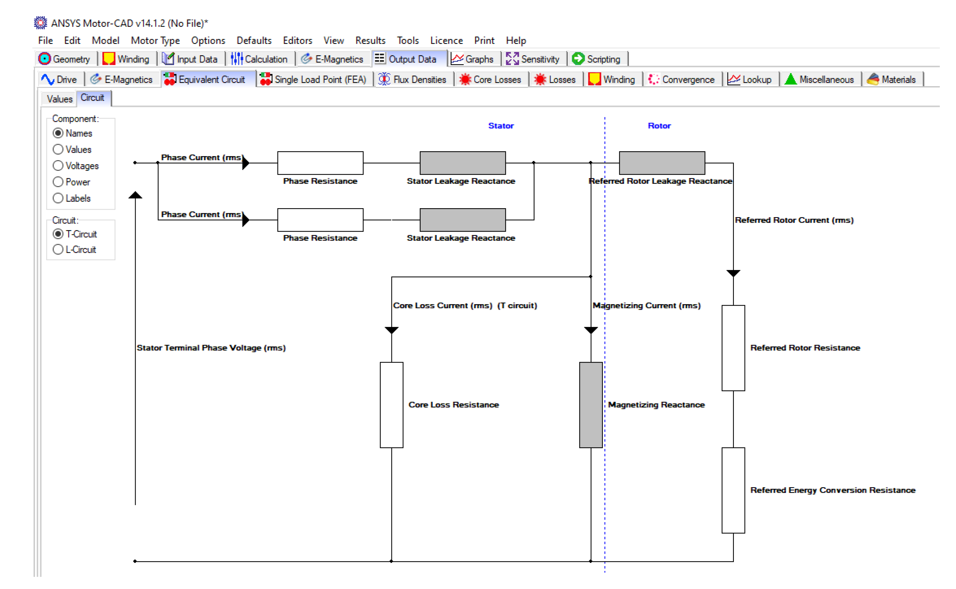
Figure 4 shows the equivalent circuit model of the designed motor using Ansys Motor CAD software.

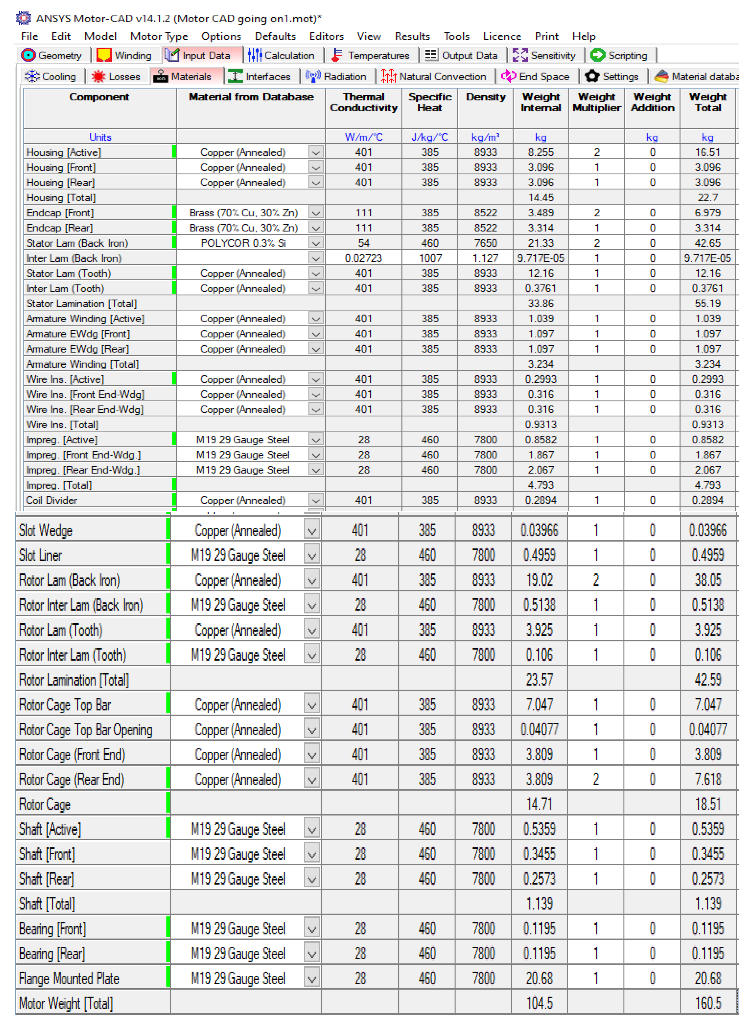
2.4.2. Material Consumptions

Figure 5 shows material consumption for a software simulation of a developed six phase induction motor.

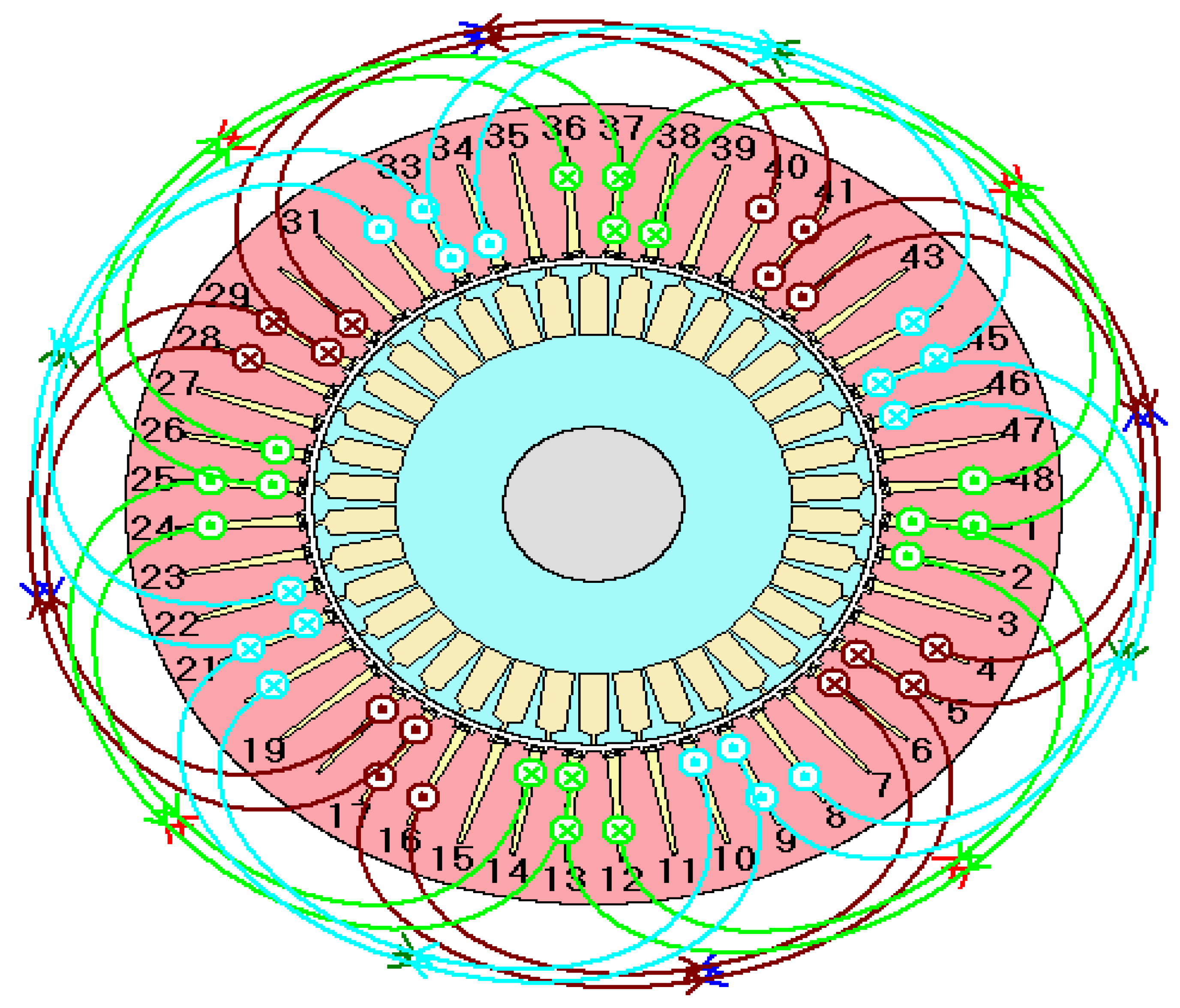
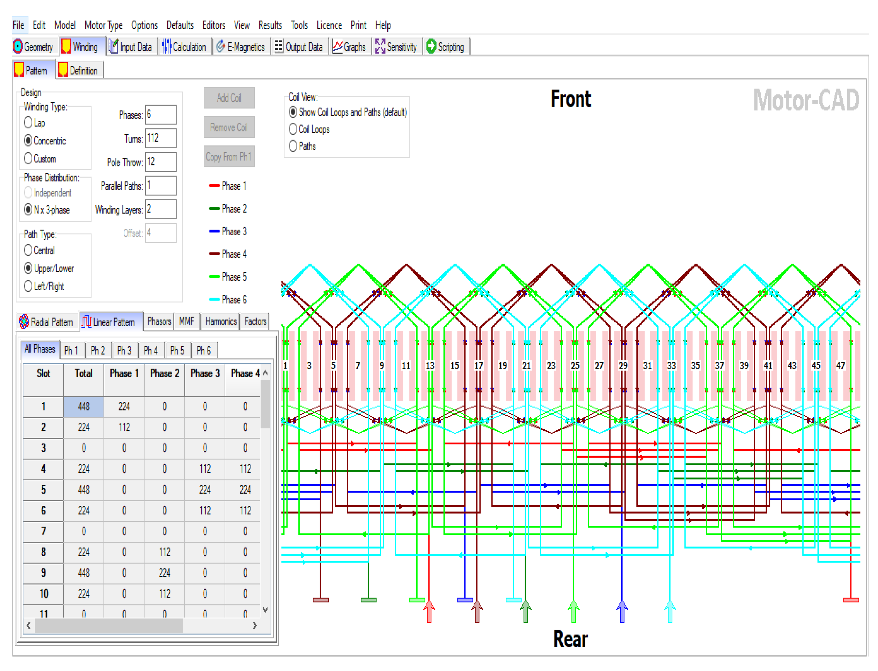
2.4.3. Winding Pattern

Figure 6 and Figure 7 show the radial pattern and linear pattern winding layouts of the designed six phase induction motor. The radial representation of the cross sectional geometry of the designed induction motor of four poles and 48 slots is plotted by using Ansys Motor-CAD. The main parameters used for this plot are summarized in Table 1. Each conductor in this motor is made up of two strands. The winding of the machine is separated into two parallel paths as can be seen in the figure below. The windings are connected in a star pattern.
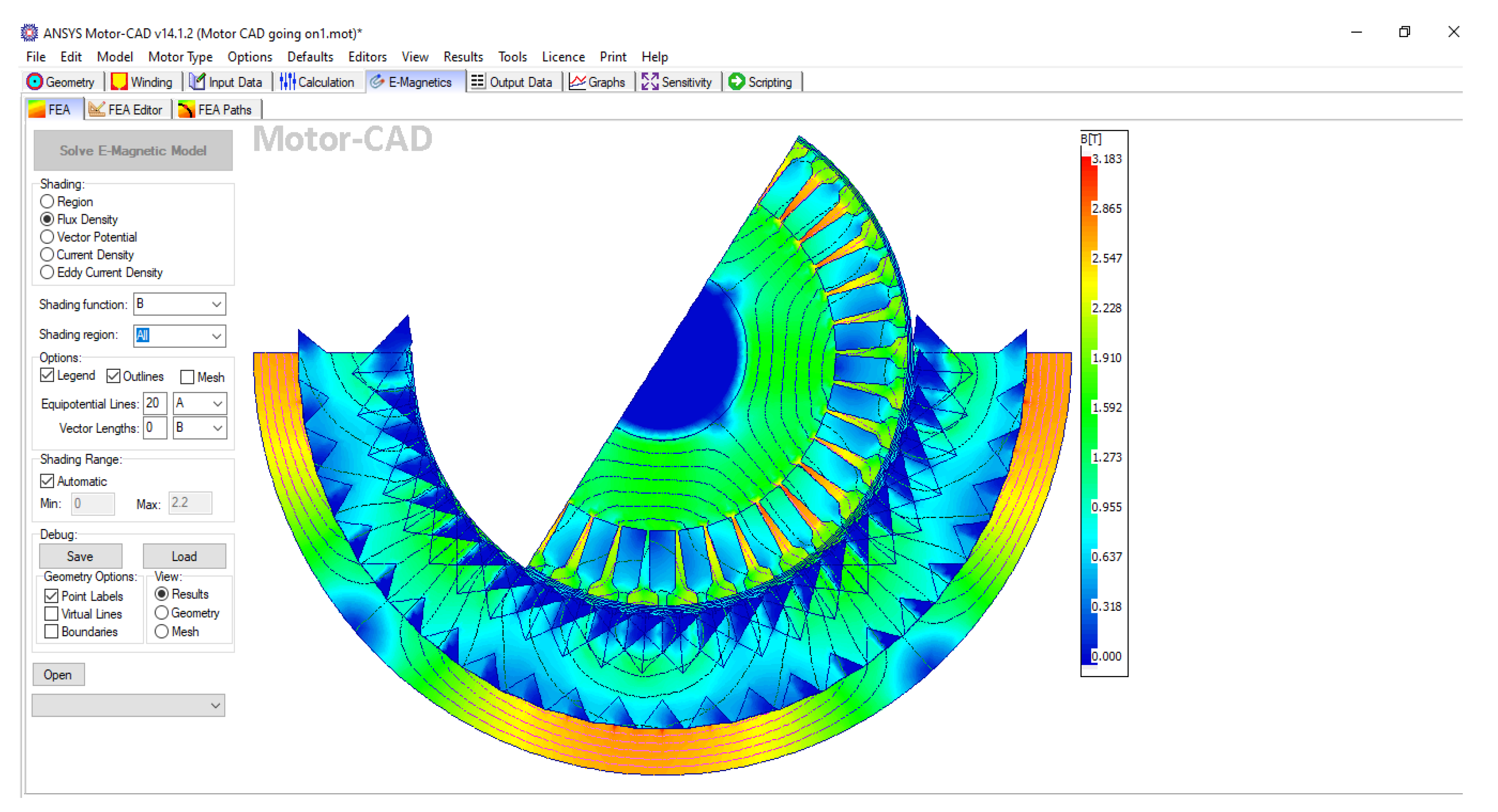
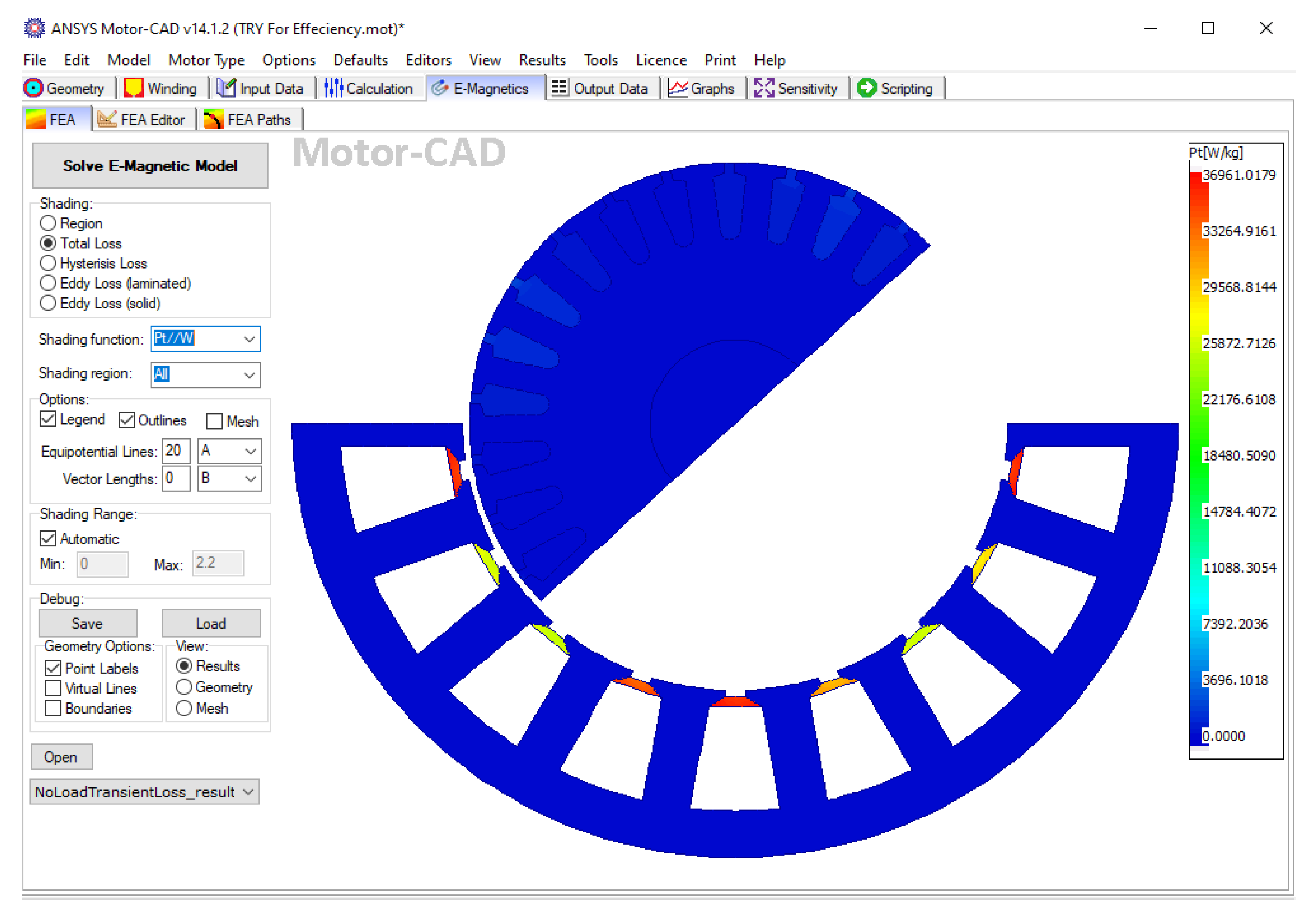
2.4.4. Flux Density

Figure 8 shows a plot of flux density in the stator and rotor of the modeled six phase IM at a rated speed. As shown in Figure 8 at the left of the figure, flux is symbolized by B, which is measured by Tesla (T). We can read the value of this flux by checking the color of the flux density in the figure and searching for the corresponding number given within that color.

2.5. Stability Analysis

Stability analysis is best performed by determining the system eigenvalue using the characteristic equation as:
d e t ( A ψ I ) = 0 .
Only if all of the real components of the eigenvalues are negative is a system considered to be stable. For the six-phase induction motor, the above stated formula produces seven state variables, which include both real and complex values. The six-phase induction motor has three complex complex conjugate pairs and one real eigenvalue is obtained. A 4-pole, 415 V, 50 Hz, a six phase induction motor is simulated [24]. Using MATLAB, the following eigenvalues are obtained. So according to the stability criteria of eigenvalues, real components of the eigenvalues are negative as shown below. −1:1176 + 0:0000i −0:1218 + 1:8114i −0:1218 − 1:8114i −0:4314 + 0:6471i −0:4314 − 0:6471i −0:0779 + 1:1749i −0:0779 − 1:1749i. This shows that the system is stable.

2.5.1. Parameters Used for PSO

In the PSO algorithm, the commonly used parameters are given in the Table 3.

2.5.2. Variables to be Optimized

Table 4 shows variables selected to be optimized.

2.5.3. Boundary Limits of Variables

The boundary limits imposed on the design are presented in Table 5.

3. Simulation Results and Discussion

3.1. Motor-CAD Lab: Efficiency Maps

The motor efficiency map is created using the ANSYS Motor CAD. After acquiring the majority of output and loss data in the operating area, the motor’s efficiency under various working situations is determined. Figure 9 shows an efficiency map of a modeled induction motor. The efficiency map is automatically displayed when the simulation is finished and different values can be plotted by changing parameters to be plotted. The graphs below are automatically generated when the calculation electromagnetic performance is finished. We can read the value of efficiency from the left of the figure based on the color or from the figure itself at different operating points. For the examination and testing of motor efficiency, the efficiency map diagram is quite useful. It can help the designer identify the most efficient and low consumption option, which will improve the overall performance. The map diagram of motor efficiency depicts the distribution of motor efficiency at various speeds and torques. It can be observed that the motor’s efficiency is low at low torque and low speed and that, as the speed increases, so does the efficiency. Furthermore, the efficiency is highest at the motor’s rated working point, with a maximum efficiency of around 96 percent.

3.2. Performance of Designed Motor

The designed motor performance is computed using Motor-CAD software with a Maximum Torque per Ampere control scheme, while taking into account the electrical constraints. Figure 9 and Figure 10 show the Torque-Speed and Power-Speed efficiency maps. Based on the weight and its dimensions, the peak power, torque and efficiency targets are met. In Motor-CAD, peak performance is determined using the optimized set of variables. The results precisely match the peak performance requirements and demonstrate a large working zone at a maximum efficiency of 95 percent.
Figure 11 indicates the loss per weight of the designed six phase induction motor optimized by Particle Swarm Optimization. As can be seen from this figure, the total loss of the designed motor is approximately around 950 W when the color of the figure is matched with grading scale to the right side. This shows that the obtained optimized loss per weight of PSO is small compared to that of others.
Running the Manual Design, Genetic Algorithm (GA) and PSO MATLAB m-file codes yields the results in Table 6. The particle swarm optimization results in a better collection of variables (X1 to X9) as indicated in Table 7, resulting in loss and weight reduction. By manual design, the losses and weights are greater compared to those of GA and PSO. It can be seen that by using PSO, the six-phase squirrel cage induction motor’s performance is improved and the losses (copper and iron) are reduced to 935.9 W, when compared with manual design and GA of 2033.7 W and 1608 W respectively. The weight of the motor is lowered to roughly 161 kg while the attaining performance increases, which is an important achievement. It has been discovered that PSO based optimal design has a higher efficiency than conventional and GA based approaches. As a result, PSO delivers greater optimization in terms of performance. Particle swarm optimization has a total loss of 935.826 W and a total weight of 161 kg which is lower than the manual design and GA, indicating that it is energy efficient. The obtained values of the various parameters demonstrate that, when compared to manual approaches, particle swarm optimization reduces the size of the motor significantly. As a result, material cost is also decreased as weight is optimized. From these design calculations and the optimization, it can be shown that the particle swarm optimization optimized design produces an efficient and smaller motor with the same rating as the manual and GA approaches.

3.3. PSO Optimized Results

Figure 12 depicts a snapshot of the problem’s optimum solution. The best value of the objective function obtained after 10 separate runs is 161.724 kg weight, as seen in Table 6. At X1 = 269.94 mm, X2 = 28 mm, X3 = 17 mm, X4 = 6 mm, X5 = 180.93 mm, X6 = 28 mm, X7 = 19 mm, X8 = 4.3 mm and X9 = 28 mm, this value is obtained as it as seen in Table 7. The eighth run, out of ten, yields the best results. The simulation took a total of 28.6892 s to complete.

4. Conclusions

In this research, a six-phase squirrel cage induction motor is optimized by particle swarm optimization resulting in improved efficiency with a minimum size of the motor. This design considers efficiency as the objective function and shows how efficient this motor is, and also considers weight as objective function, showing the optimized motor’s weight. The total losses are reduced from 2.0337 KW to 1.608 KW in the case of the genetic algorithm and 0.9359 KW in the case of PSO optimization using a MATLAB simulation. This optimized value of total power loss, calculated using PSO, is determined to be 935.9 W, obtained from the MATLAB simulation. As a result of the reduced total power loss, the motor’s efficiency increased from 91 percent to 95 percent. It can be deduced from this that the efficiency of an induction motor is inversely proportional to the losses. The optimally designed motor’s weight is decreased from 200 kg to 160.5 kg, as compared to the conventionally designed motor. The weight of the motor is also lowered while the attaining performance increases, which is an important achievement. This demonstrates that the losses and weights of a six phase induction motor can be greatly decreased by PSO optimization. In the study, the particle swarm algorithm outperformed the manual design and GA. This research makes a significant contribution to a fascinating issue in the field of electric motor design and other technical applications. Finally, the system stability is checked and satisfied for the tested stability condition.

Author Contributions

Conceptualization, T.T.; methodology and software validation L.W.; formal analysis and review, T.A.; supervision, A.T.; writing, editing, S.L.; and visualization, S.U. All authors have read and agreed to the published version of the manuscript.

Funding

Princess Nourah bint Abdulrahman University Researchers Supporting Project number (PNURSP2022R79), Princess Nourah bint Abdulrahman University, Riyadh, Saudi Arabia.

Institutional Review Board Statement

Not applicable.

Informed Consent Statement

Not applicable.

Data Availability Statement

The data that support the findings of this study are available from authors upon reasonable request.

Acknowledgments

Princess Nourah bint Abdulrahman University Researchers Supporting Project number (PNURSP2022R79), Princess Nourah bint Abdulrahman University, Riyadh, Saudi Arabia.

Conflicts of Interest

The authors declare no conflict of interest.

Abbreviations

PSOParticle Swam Optimization
ACAlternating Current
MwMegawatt
SPIMSix Phase Induction Motor
FEAFinite Element Analysis
GAGenetic Algorithm
BavAir gap flux density or Specific Magnetic loading
acSpecific Electric loading
Dstator core diameter
Lcore length of stator
Qinput apparent power
KVAKilo Volt Ampere
C0Output coefficient
vPeripheral Velocity
KVAKilo Volt Ampere

References

  1. Singh, G.K. Multi-phase induction machine drive research—A survey. Electr. Power Syst. Res. 2002, 61, 139–147. [Google Scholar] [CrossRef]
  2. Akpama, E.J. Six Phase Induction Motor Modelling For Submarine Application. J. Electr. Electron. Eng. 2018, 13, 61–66. [Google Scholar]
  3. Ali, E.; Ghosh, B.C. Comparison of Performances of Six Phase Induction Motor Consisting of Dual Three Phase Windings fed from Sinusoidal Voltage and Current Sources under Normal and Abnormal Operating Conditions. Int. J. Innov. Eng. Technol. 2019, 14, 31–38. [Google Scholar]
  4. Abunike, E.C.; Okoro, O.I.; Umoh, G.D. Steady and dynamic states analysis of induction motor: Fea approach. Niger. J. Technol. 2017, 36, 1202–1207. [Google Scholar] [CrossRef] [Green Version]
  5. Francis, J.; Aby, B.N.; Johnson, A.; Mathew, J.; Sreepriya, R.; Sankar, V. Comparison of Six Phase and Three Phase Induction Motors for Electric Vehicle Propulsion as an Improvement Toward Sustainable Transportation. In Green Buildings and Sustainable Engineering; Springer: Singapore, 2019; Volume 1, pp. 239–247. [Google Scholar]
  6. Iduh, S.E.; Omugbe, S.E. The design and practical implementation of a six-phase induction motor. J. Adv. Sci. Eng. 2020, 3, 1–77. [Google Scholar] [CrossRef]
  7. Pal, B.K.; Prajapati, P.; Bajaj, M.; Singh, S. Control of Grid Side Converter for Grid Connected Six Phase Induction Generator. In Proceedings of the IEEE ICCCCM 2013, Allahabad, India, 3–4 August 2013; pp. 1–7. [Google Scholar]
  8. James, A.E.; Anih, L.; Okoro, O. Transient Analysis and Modelling of Sixphase Asynchronous Machine. Am. J. Electr. Power Energy Syst. 2015, 4, 77–83. [Google Scholar] [CrossRef]
  9. Yetgin, A.G.; Turan, M.; Cevher, B.; Çanakoğlu, A.İ; Ayhan, G.Ü.N. Squirrel Cage Induction Motor Design and the Effect of Specific Magnetic and Electrical Loading Coefficient. Int. J. Appl. Math. Electron. Comput. 2018, 7, 1–8. [Google Scholar] [CrossRef]
  10. Rivière, N.; Villani, M.; Popescu, M. Optimisation of a High Speed Copper Rotor Induction Motor for a Traction Application. In Proceedings of the IECON 2019—45th Annual Conference of the IEEE Industrial Electronics Society, Lisbon, Portugal, 14–17 October 2019; pp. 2720–2725. [Google Scholar]
  11. Das, P.P.; Mahato, S.N. Prasanna; Design Optimization of a Six-Phase Induction Motor by Flower pollination and Modified Artificial Bee colony Algorithms. In Proceedings of the 2016 IEEE Region 10 Conference (TENCON), Singapore, 22–25 November 2016; pp. 3315–3317. [Google Scholar]
  12. Akpama, E.J. Modelling Of Six-Phase Induction Machine Including Saturation Effect. J. Multidiscip. Eng. Sci. Technol. 2019, 6, 2458–9403. [Google Scholar]
  13. Gupta, A.; Machavaram, R.; Kshatriya, T.; Ranjan, S. Multi-Objective Design Optimization of a Three Phase Squirrel Cage Induction Motor for Electric Propulsion System using Genetic Algorithm. In Proceedings of the 2020 IEEE First International Conference on Smart Technologies for Power, Energy and Control (STPEC), Nagpur, India, 25–26 September 2020; pp. 25–26. [Google Scholar]
  14. Sakthivel, P.; Bhuvaneswari, R.; Subramanian, S. Economic Design of Three-Phase Induction Motor by Particle Swarm Optimization. Electromagn. Anal. Appl. 2010, 2, 301–310. [Google Scholar] [CrossRef] [Green Version]
  15. Slimene, M.B. Performance analysis of six-phase induction machine multilevel inverter with arbitrary displacement. Electr. Eng. Electromech. 2020, 4, 12–16. [Google Scholar] [CrossRef]
  16. Abdullah, A.T.; Ali, A.M. Thermal analysis of a three-phase induction motor based on motor-CAD, flux2D, and matlab. Indones. J. Electr. Eng. Comput. Sci. 2019, 15, 46–53. [Google Scholar] [CrossRef]
  17. Mohamed, M.Y.; Fawzi, M.; Maksoud, S.A.A.; Kalas, A.E. Finite Element Analysis of Multi-Phase Squirrel Cage Induction Motor to Develop the Optimum Torque. In Proceedings of the 2019 IEEE Conference on Power Electronics and Renewable Energy (CPERE), Aswan, Egypt, 23–25 October 2019; pp. 504–510. [Google Scholar]
  18. Sivaraju, S.S.; Devarajan, N. GA Based optimal design of three phase squirrel cage induction motor for enhancing performance. Int. J. Adv. Eng. Technol. 2016, 2, 202–206. [Google Scholar]
  19. Mohammadi, H.R.; Akhavan, A. Parameter Estimation of Three-Phase Induction Motor Using Hybrid of Genetic Algorithm and Particle Swarm Optimization. J. Eng. 2014, 2014, 148204. [Google Scholar] [CrossRef] [Green Version]
  20. Lodewijks, G.; Cao, Y.; Zhao, N.; Zhang, H. Reducing CO2 Emissions of an Airport Baggage Handling Transport System Using a Particle Swarm Optimization Algorithm. IEEE Access 2021, 9, 121894–121905. [Google Scholar] [CrossRef]
  21. Lin, C.H. Altered Grey Wolf Optimization and Taguchi Method with FEA for Six-Phase Copper Squirrel Cage Rotor Induction Motor Design. Energies 2020, 13, 2282. [Google Scholar] [CrossRef]
  22. Dainez, P.S.; Bim, E. A New Multiphase Rotor Model for the Squirrel Cage Rotor of a Six-phase Induction Machine. In Proceesings of the IECON 2018—44th Annual Conference of the IEEE Industrial Electronics Society, Washington, DC, USA, 21–23 October 2018; pp. 21–23. [Google Scholar]
  23. Abdel-Khalik, A.S.; Abdel-Majeed, M.S.; Ahmed, S. Effect of Winding Configuration on Six-Phase Induction Machine Parameters and Performance. IEEE Power Energy Soc. Sect. 2020, 8, 223009–223020. [Google Scholar] [CrossRef]
  24. Das, P.P.; Mahato, S.N. Artificial Bee Colony Based Design Optimization of a Six-Phase Induction Motor. In Proceedings of the 2016 2nd International Conference on Control, Instrumentation, Energy & Communication (CIEC), Kolkata, India, 28–30 January 2016; Volume 23, pp. 526–530. [Google Scholar]
Figure 1. Overall Flowchart of the System Design.
Energies 15 02994 g001
Figure 2. A Flowchart of PSO Algorithm.
Energies 15 02994 g002
Figure 3. A Cross Section of Stator core and Rotor core.
Energies 15 02994 g003
Figure 4. Equivalent Circuit Obtained from ANSYS MotorCAD.
Energies 15 02994 g004
Figure 5. Material Consumptions of Designed Motor.
Energies 15 02994 g005
Figure 6. Radial Pattern of the Six Phase Induction Motor Winding.
Energies 15 02994 g006
Figure 7. Linear Pattern of the Six Phase Induction Motor Winding.
Energies 15 02994 g007
Figure 8. Plot of Flux Density.
Energies 15 02994 g008
Figure 9. Optimized Efficiency Map of Designed Motor.
Energies 15 02994 g009
Figure 10. Shaft Power of Designed Motor.
Energies 15 02994 g010
Figure 11. Loss per Weight of Designed Motor.
Energies 15 02994 g011
Figure 12. PSO Convergence Time.
Energies 15 02994 g012
Table 1. Stator and Rotor Parameters.
Stator ParametersValueRotor ParametersValue
Slot number48Slot number38
Stator lamination Diameter296 mmPole numbers4
Stator bore195 mmBar opening1 mm
Tooth width11 mmBar opening depth1 mm
Slot depth22 mmBar tip angle45°
Tooth tip depth1.5 mmRotor tooth width18 mm
Slot opening1 mmAir gap11 mm
Tooth tip angle30°Shaft diameter27 mm
Table 2. General Design Data.
Output Power30 hpFriction & windage losses3% of output power
Input voltage380 VStray losses1% of output power
Number of poles4Operating temperature75 ℃
Speed1470 rpmOperation motorMotor
Table 3. Parameters Used for PSO.
ParameterValue
Population size100
Inertial weight minimum0.4
Inertial weight maximum0.9
Acceleration factors C12
bf Acceleration factors C22
Table 4. Variables to be optimized.
Variable NameRepresented Variables
Stator Outer DiameterX1
Stator Core DiameterX2
Stator Slot DiameterX3
Stator Tooth WidthX4
Stator Bore DiameterX5
Rotor Core DiameterX6
Rotor Slot DiameterX7
Rotor tooth widthX8
Stator Core LengthX9
Table 5. Boundary limits of variables.
VariablesLower Boundary (LB)Upper Boundary (UB)
X10.210.27
X20.0280.032
X30.0170.022
X40.06450.0665
X50.180.21
X60.0760.0885
X70.0880.092
X80.00350.005
X90.180.24
Table 6. Comparison of Design Optimization Techniques.
NoParametersManual DesignGAPSO
1Stator Bore Diameter195 mm189.97 mm180.93 mm
2Stator Outer Diameter298 mm278.98 mm269.94 mm
3Stator Core Length230 mm240 mm240 mm
4Airgap Length0.6235 mm0.603 mm0.5931 mm
5Rotor Outer Diameter194 mm188.76 mm179.76 mm
6Rotor Inner Diameter100 mm97.67 mm87.688 mm
7Total Power Loss2.0337 Kw1.608 Kw0.9359 Kw
8Rated Slip0.020.01540.012
9Input Power24.434 Kw24.008 Kw23.336 Kw
10Rated Efficiency0.91680.9330.953
11Rated Power Factor0.83450.84990.8767
12Rated Torque145.5 Nm154.66 Nm162 Nm
13Peripheral Velocity15.395 m/s14.92 m/s14.21 m/s
14Stator Slot Pitch12.76 mm12.43 mm11.84 mm
15Mean Turn Length1050 mm815 mm808 mm
16Stator Core Depth29.5 mm28 mm28 mm
17Net Core Length207 mm192.4 mm192.4 mm
18Stator Slot Diameter22 mm17 mm17 mm
19Rotor Slot Pitch9 mm8.075 mm7.25 mm
20Weight of motor200 kg188.6857 kg160.5 kg
Table 7. PSO Optimized Variables.
VariablesValues
X1269.94 mm
X228 mm
X317 mm
X46 mm
X5180.93 mm
X628 mm
X719 mm
X84.3 mm
X9240 mm
Publisher’s Note: MDPI stays neutral with regard to jurisdictional claims in published maps and institutional affiliations.

