Article

Modeling a Hybrid Reformed Methanol Fuel Cell–Battery System for Telecom Backup Applications

1
AAU Energy, Aalborg University, 9220 Aalborg, Denmark
2
Blue World Technologies ApS, Lavavej 16, 9220 Aalborg, Denmark
*
Author to whom correspondence should be addressed.
Submission received: 14 March 2022 / Revised: 22 April 2022 / Accepted: 25 April 2022 / Published: 28 April 2022
(This article belongs to the Special Issue Advances in Hydrogen Energy Ⅱ)

Abstract

:
In this paper, a hybrid reformed methanol fuel cell–battery system for telecom backup applications was modeled in MATLAB Simulink. The modeling was performed to optimize the operating strategy of the hybrid system using an energy management system with a focus on a longer lifetime and higher fuel efficiency for the fuel cell, while also keeping the state-of-charge (SOC) of the battery within a reasonable range. A 5 kW reformed methanol fuel cell stack and a 6.5 kWh Li-ion battery were considered for the hybrid model. Moreover, to account for the effects of degradation, the model evaluated the performance of the fuel cell both in the beginning of life (BOL) and after 1000 h and 250 start–stop cycling tests (EOT). The energy management system (EMS) was characterized by 12 operating conditions that used the battery SOC, load requirements and the presence or absence of grid power as the inputs to optimize the operating strategy for the system. Additionally, the integration of a 400 W photovoltaic (PV) system was investigated and was able to supplement the battery SOC, thereby increasing the stability and reliability of the system. However, extensive power outages during the night could lead to low battery SOC and, therefore, critical operating conditions and the extended use of the fuel cell. The model also predicted the methanol consumption for different scenarios.

1. Introduction

The telecommunications industry is growing rapidly worldwide and global connections are expected to increase to over 100 billion by 2025 [1]. Additionally, 5G alone could cause a 160% increase in the energy consumption of the global wireless ecosystem [2]. Even though the maximum power consumption of a 5G base station is between 1000–1400 W, since the range of 5G bands is smaller than those of 4G bands, several bands will have to be allocated in the same area, which will lead to a higher power consumption [1,3]. The most common configuration for this technology is to set several bands in a specific area, up to ten by 2023, for which the expected consumption is around 11.6 kW, which is 1.7 times more than 4G technology [1,4]. Therefore, greener backup power systems need to be deployed both to guarantee network stability and to address the environmental impact of the increased power consumption.
Moreover, developing countries are facing a fast and demanding energy transition, which calls for the development of clean, reliable and economical backup power systems. For instance, over the past 20 years in India, the energy consumption has almost doubled and the possibility of an even more rapid growth is on the horizon [5]. New targets for the reduction in carbon emissions have been defined and the large-scale harnessing of green energy is considered to be one of the main ways to achieve them [6]. India is the second largest country in the telecommunications market and is only surpassed by China as the country with the highest number of subscriptions, with four times more subscriptions than the USA in 2019, which is the country in the third place [5]. Several factors have been responsible for this demanding and quick growth, such as fair prices for telecom services, 4G and 5G services and the rapid rate of foreign investment [7].
The telecommunications industry depends heavily on backup power systems to guarantee the service reliability of telecom towers in the event of power disruptions that are caused by extreme weather conditions or normal power shortages. According to a California bill from 2008, a backup power of 8 h is more than sufficient for the majority of power outages in that area, with the requirement that the recharge time for a battery-based backup power system is less than 24 h after outages [8]. The demands for backup capacity by local authorities can vary depending on the location, with some coastal areas in the USA requiring up to 72 h of safe and reliable operation for telecommunication services during power outages and severe flooding [8,9].
Traditional backup power systems are based on lead–acid battery systems or diesel generators. Even though batteries have qualities such as a low cost and the ability to maintain a consistent performance until they need recharging, they only have a limited energy density and suffer from a high sensitivity to temperature [10,11]. On the other hand, diesel generators are suitable for long run times and have a high degree of reliability, but they are characterized by a high maintenance cost, high pollution emissions and noise. Nowadays, a third power system that is based on proton exchange membrane fuel cells (PEMFCs) is gaining popularity within the backup power system market due to its cleaner and quieter operation and lower maintenance cost compared to diesel generators. Other advantages of PEM fuel cells include compactness, reliability, high energy density, high efficiency and a wide range of operating temperature [12]. However, they have a relatively high capital cost compared to conventional power sources and their start and transient dynamics are slow compared to battery-only solutions.
In the literature, hybrid fuel cell–battery systems have been predominantly investigated for transportation applications, mainly for the automotive and maritime industries. However, some research has been conducted on the topic of backup power applications [13,14,15,16] and it has been found that system dynamics and efficiency can be enhanced [17]. Moreover, since two power sources are used in hybrid systems, the size and cost of the system can be reduced [18,19].
From a logistics point of view, the choice of hydrogen carrier is important since most cell towers are located in remote locations and do not have easy access to re-fueling. There are different ways to provide hydrogen for the fuel cell, such as compressed hydrogen, liquefied hydrogen, hydrogen storage in metal hydrides and hydrogen storage in the chemical bonds of other hydrocarbons and alcohols via power-to-X (PtX) processes. Considering that up to 72 h of backup capacity is required and that the liquefaction and compression of hydrogen are expensive, the chemical storage of hydrogen in liquid hydrocarbons and alcohols, such as methanol, is one of the most practical approaches. Since methanol can be produced locally from renewable resources, a hybrid solution that employs a liquid methanol-fueled fuel cell and a battery solves many of the above-mentioned issues of traditional backup power systems.
In this paper, a hybrid system consisting of a reformed methanol-fed high temperature PEMFC (HT-PEMFC) and a battery pack is proposed as a backup solution for telecommunication services. This was carried out by means of a state-based energy management system (EMS), which aimed to extend the lifetime of the fuel cell and keep the battery SOC within a certain range of values in order to avoid thermal stresses and degradation. Moreover, the addition of a solar PV module to supplement the load requirements was investigated.

2. Methodology

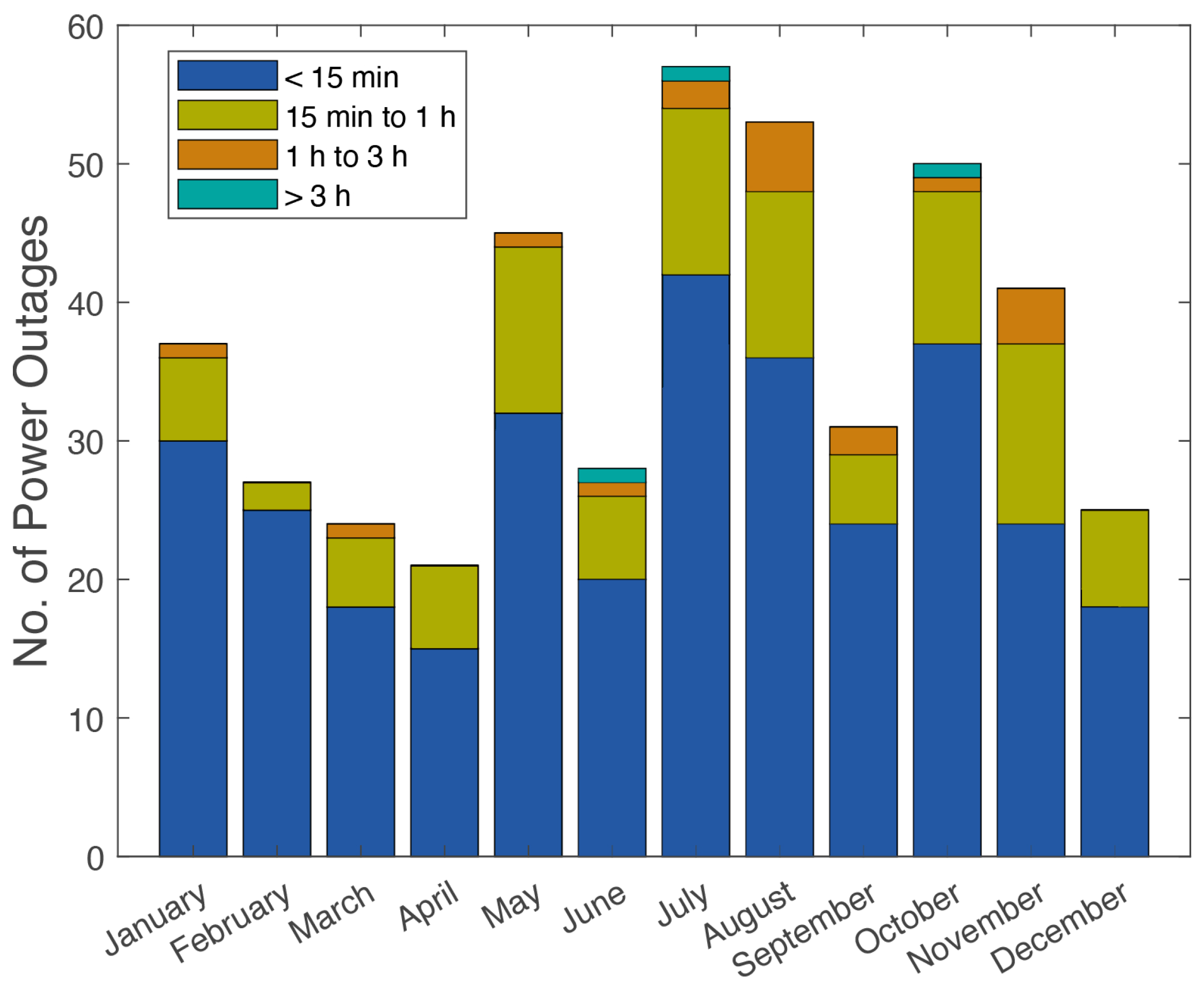
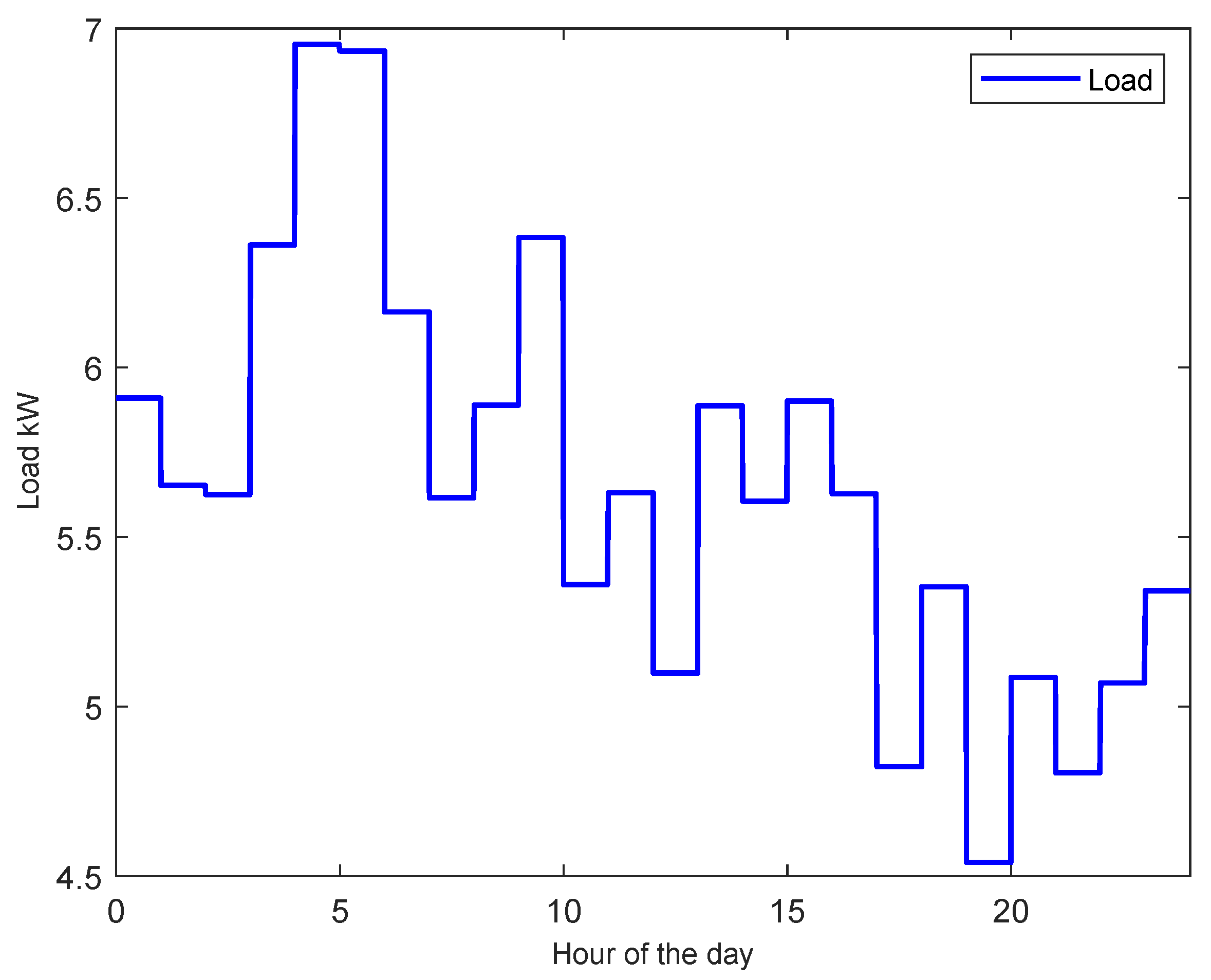
Load Profile and Power Outages

As previously mentioned, power outages in developing countries are common, as can be seen in Figure 1. Two main categories are considered: short interruptions and long interruptions. Within short interruptions, two subcategories are defined: “less than 15 min” and from “15 min to 1 h”. Long interruptions are also divided into two categories: "1 to 3 h" and “more than 3 h”. As shown in Figure 1, the majority of power outages fall into the first subcategory. However, power outages that last for longer than 3 h are also a reality, as was seen in June, July and October 2020 in Kapoorthla.
For the model in the current work, a somewhat realistic hypothetical power outage scenario was prepared that was based on the power outage duration distribution data from [20], as shown in Figure 1, from which the month of July was chosen as the worst month in terms of power outages. In Figure 2, the power outages in July 2020 in Kapoorthla, Lucknow, India, are shown according to the duration of the outage. It can be seen that 74% of the power outages lasted for less than 15 min and only 6% lasted for longer than 1 h.
Along with the duration and distribution of the power outage, the load demand of the telecom tower was another important parameter in the design of the hybrid backup power system. Figure 3 illustrates the possible daily load demand of the telecom tower that was used as a basis for this work, for which the maximum value was around 7 kW and the minimum value was 4.5 kW. Additionally, the same daily load profile was used for all investigated scenarios in this paper since the changes in the power consumption of the telecom traffic from one day to another could be said to be minimal [6].

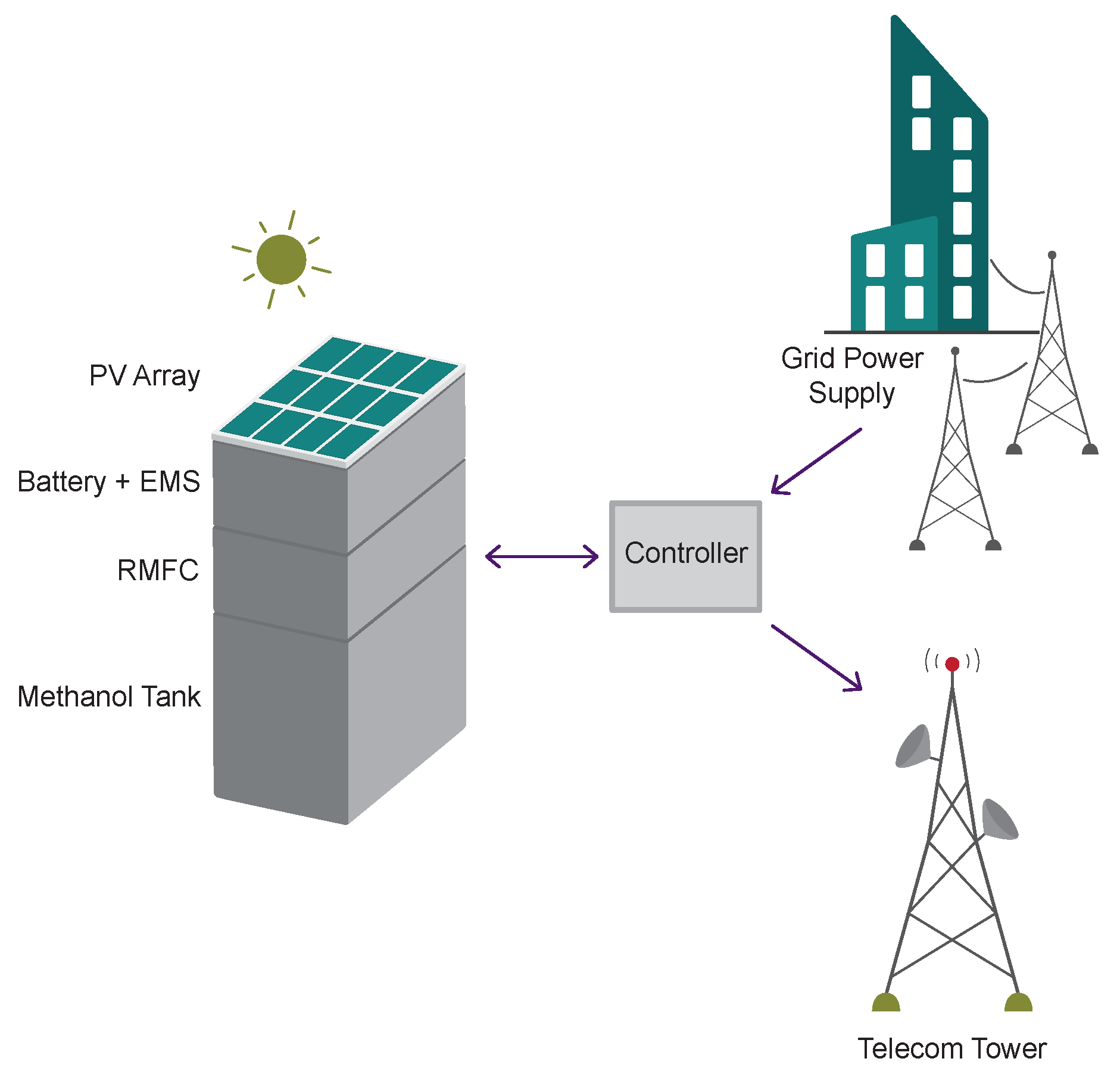
3. Hybrid System Model

The hybrid system that was developed in this work was based on the synergy between the fuel cell and the battery. These two components had to be able to respond when a power failure occurred. An illustration of the hybrid fuel–battery system as a backup power source for a telecom tower is shown in Figure 4. The main aim of the model was to keep the fuel cell within the optimal operation region and avoid unnecessary stresses in order to extend the lifetime of its components. The hybrid system was expected to respond promptly, as soon as a power outage occurred. The system was modeled, both with and without the PV system, in MATLAB Simulink and the following considerations were made:
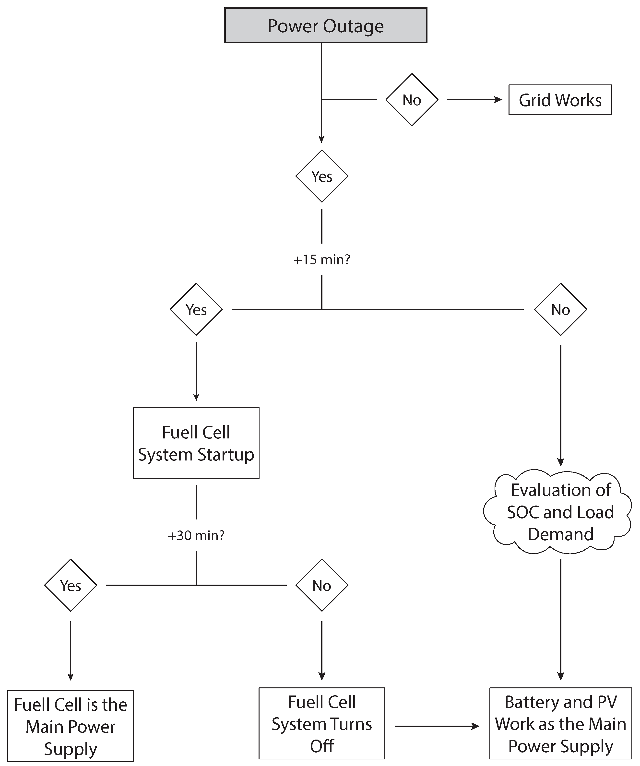
  • The startup time of the reformer and the fuel cell (RMFC) was assumed to be 30 min;
  • The the fuel cell dynamics were not considered and no delay was assumed when changing the fuel cell load;
  • The PV system provided power to the battery whenever available.
As already mentioned, the majority of power outages are shorter than 15 min. With hybrid systems, these short power outages can be mitigated using the battery alone when they occur with long enough intervals in between one another to allow for the battery to fully recharge. After the first 15 min of power failure, the fuel cell system is triggered and it is assumed that the system takes 30 min to achieve the desired operating conditions. This assumption was critical for our model as it required the battery to always supply power for the first 45 min of a power outage. When the grid power resumed, it simultaneously charged the battery and provided the required power to the telecom tower. However, for power outages of longer than 45 min, the entire hybrid system would operate, including the fuel cell. The algorithm for the operation strategy of the EMS for the hybrid backup power system on which the model was based is shown in Figure 5.

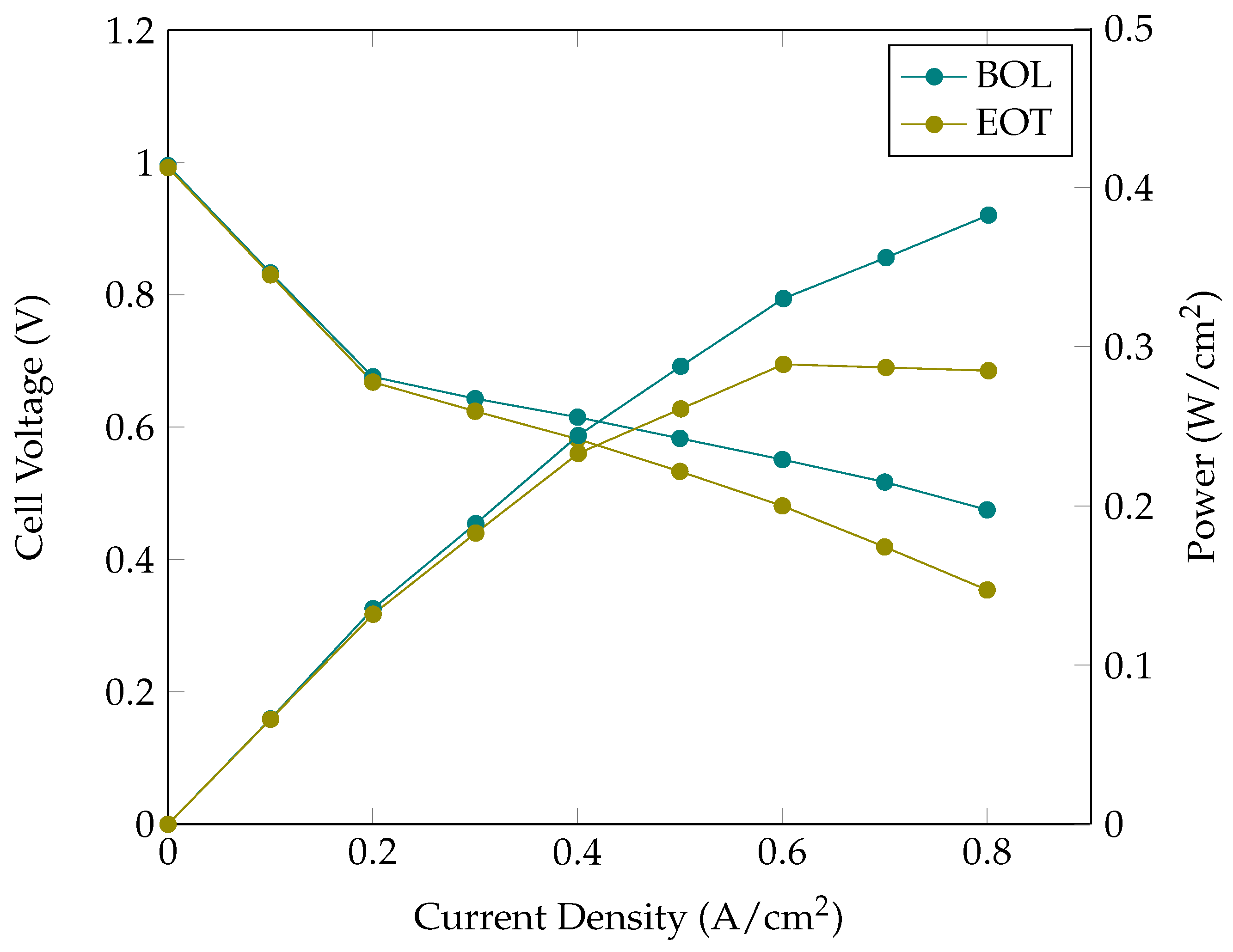
3.1. Fuel Cell and Battery Model
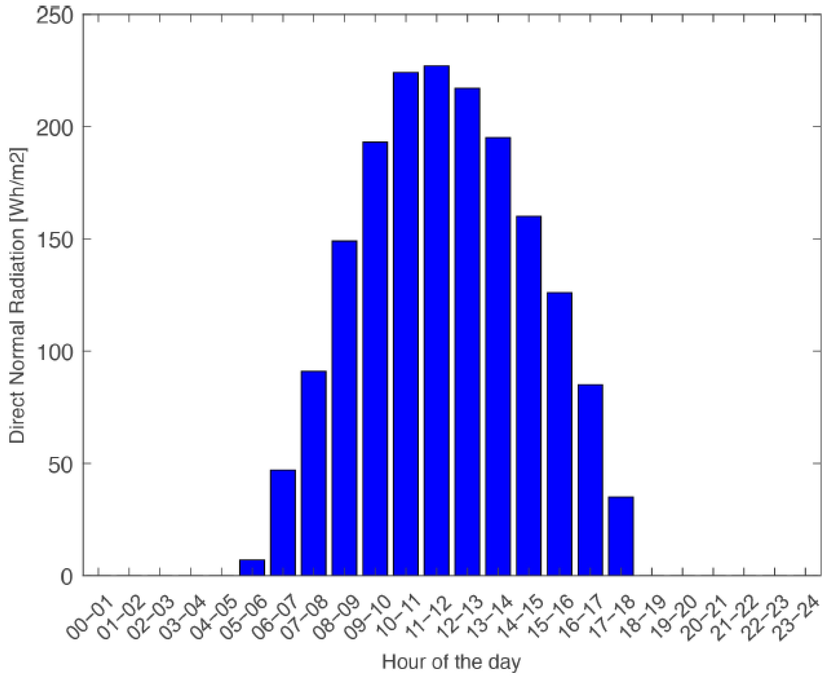
Look-up tables that were based on the polarization data of a 5 kW stack were used to extract the operating current density and the voltage of the fuel cell for the model. Figure 6 shows the cell-averaged polarization curve of the fuel cell stack, both at the beginning of life (BOL) and after 1000 h and 250 start–stop cycles (EOT).
The battery current and voltage was modeled as:
I b a t = V O C V b a t V O C V b a t 2 4 × R × P 2 × R
V b a t = V O C V b a t R × I b a t
where I b a t is the battery current ( A ) , V O C V b a t ( V ) is the battery open circuit voltage (which was a function of the state-of-charge of the battery), R is the internal resistance of the battery ( Ω ) (which was determined using the look-up tables that were based on experimental data [21]), P is the battery power consumption ( W ) [22] and V b a t ( V ) is the battery voltage. A lithium-ion battery was chosen due to its high energy density compared to other battery technologies, its high efficiency during charging and discharging and its low self-discharge rate [23]. The battery’s instantaneous SOC was calculated as follows:
S O C = S O C i n i η × I b a t Q d t
where Q is the capacity of the battery and η is the efficiency of charging and discharging, which was considered to be 100%. The resistance of charging and discharging was assumed to be the same. The technical specifications of the hybrid fuel cell–battery system are presented in Table 1.
The hydrogen consumption was estimated using the following equation to calculate the molar flow rate of hydrogen [24]:
N ˙ H 2 = λ a × N c e l l s × J × A c e l l 2 × F
where F is the Faraday constant (96,485 s A mol ), J is the current density, λ a is the anode stoichiometric ratio, N c e l l s is the number of cells in the stack and A c e l l is the active area of the fuel cell. After considering the ideal gas equation, the volumetric flow rate was obtained as follows:
Q ˙ H 2 = N ˙ H 2 × R × T p
where T is temperature, R is the ideal gas constant (8.3145 J mol K ) and p is pressure. The fuel consumption of each scenario was estimated based on the stoichiometric ratios of the steam methanol reformation (CH3OH + H2O→ 3H2 + CO2) and with the assumption of ideal gas behavior.

3.2. PV Model

A solar cell, or photovoltaic cell (PV), is an electrical device that converts direct light into electricity through the photovoltaic effect. The output of a photovoltaic cell is dependent on the incidence of the light. The following equations were used to model the PV system [25]. The thermal voltage equation that described the average energy in the random movement of the electrons at a certain temperature was given by:
V T = k B × T o p t q
where V T is the thermal voltage, k B is the Boltzmann constant (1.38   ×   10 23 J / K ), T o p t is the operating temperature and q is the electron charge. Furthermore, the current through a diode as a function of voltage was given as follows:
I D = N p × I s [ e ( V N s + I R s N s ) / ( N × V T × C ) 1 ]
where I D is the diode current, V is the voltage, N p is the number of cells in parallel, I is the current, R S is the series resistance of the cell, N is the ideality factor, I S is the reverse saturation current, N s is the number of cells in series and C is the number of cells in the module. Additionally, the load current equation was given by:
I L = I P h × N p I D I S H
where I L is the load current, I P h is the photocurrent and I S H is the shunt current. The photocurrent is the current that flows through the solar cell that is induced by the sunlight. The photocurrent in this study was given by:
I P h = [ k i × ( T o p t T r e f ) + I S C ] × I r r
where T r e f is the reference operating temperature, I S C is the short circuit current (3.8 A), k i is the current proportionality constant (2.2 × 10 3 ) and I r r is the irradiance. Additionally, the shunt current equation was also modeled and was given by:
I S H = ( I × R s + V ) R S H
where I S H is the shunt current, R S H is the shunt resistance of the cell and R S is the series resistance of the cell. For the reverse saturation current of the diode, the equation was given by:
I S = I R S × ( T o p t T R e f ) 3 × q 2 × E g N × k B × e 1 T o p t 1 T r e f
where I S is the reverse saturation current of the diode and I R S is the reverse current. The reverse current was modeled as:
I R S = I S C [ e q × V O C V P V k i × C × T o p t 1 ]
where V O C V P V is the open circuit voltage and C is the number of cells in the PV module. The two main inputs of the PV system were the irradiance and the operating temperature. The average daily irradiance profile during July in Lucknow, India, is shown in Figure 7 [26]:
Since July was the worst month for power outages, the solar irradiation levels in July were considered for the PV model. It was assumed that the PV output was always at the maximum value for each hour, considering each irradiation value. The operating temperature was considered to be constant at 25 ° C throughout the day.

3.3. Energy Management System (EMS)

An energy management system was modeled to evaluate and use different defined limits of the battery SOC to split the power demand between the fuel cell and the battery, based on the load requirements of the cell tower during a power outage. The load profile shown in Figure 3 was used to simulate the response of the system.
This energy management strategy was based on a rule-based control system [27], for which the parameters, such as the current and voltage of the fuel cell and battery, were either defined using look-up tables or modeled mathematically [16,17]. This state-based energy management system was characterized into 12 operating conditions using human intuition and mathematical modeling, according to low, medium and high SOCs for the battery. Similarly, the required load was categorized into different intervals based on the fuel cell power output: low, medium-low, medium-high and high. So, when the load that was required from the hybrid system by the cell tower (P b a c k u p ) was less than the minimum operating point of the fuel cell ( P F C m i n ), it was considered as low load and when the P b a c k u p was between the P F C m i n and the optimum operating point (P F C o p t ), then P b a c k u p was considered to be medium-low load. It was considered to be a medium-high load when the P b a c k u p was in between P F C o p t and the maximum operating point of the fuel cell (P F C m a x ). Finally, the P b a c k u p during a power outage was assessed to be a high load when its value was higher than P F C m a x . With the battery SOC and fuel cell power output as the operational thresholds of the system, the EMS that is shown in Table 2 was developed.
The EMS also considered the effects of degradation, due to which the three operating points of the fuel cell, P F C m i n , P F C o p t and P F C m a x , had lower values after 1000 h of operation and 250 start–stop cycles. It should be noted that when the power that was required by the tower was less than the power being produced by the fuel cell, the fuel cell stack also charged the battery to avoid low SOC and thermal stresses [28]. Additionally, a DC–DC converter was used in the hybrid power system and its efficiency was considered to be 100%.

4. Results

The modeling work in this paper aimed to investigate a hybrid fuel cell–battery system as a backup solution for telecommunication applications. This hybrid system combined the advantages of both battery and fuel cell systems into a clean and environmentally friendly solution, thereby avoiding the disadvantages of diesel generators.
The response of the system to different scenarios was studied. Based on the length of the power outage, two scenarios were identified: a possible daily scenario, which represented a day with both short and long power outages, and a worst case scenario, for days with only long power outages.To account for the degradation of the fuel cell, the performance of the fuel cell was considered both at the beginning of life and after 1000 h of operation and 250 start–stop cycles. While previous works have evaluated how the initial battery SOC affects the behavior of the entire system for hybrid fuel cell–battery passenger vessels [17], in this paper, the initial SOC was considered to be at 100% for all scenarios due to the unpredictability of power outages. In addition to the battery and the fuel cell system, a 400 W PV was also analysed for its effects on the stability of the hybrid system.

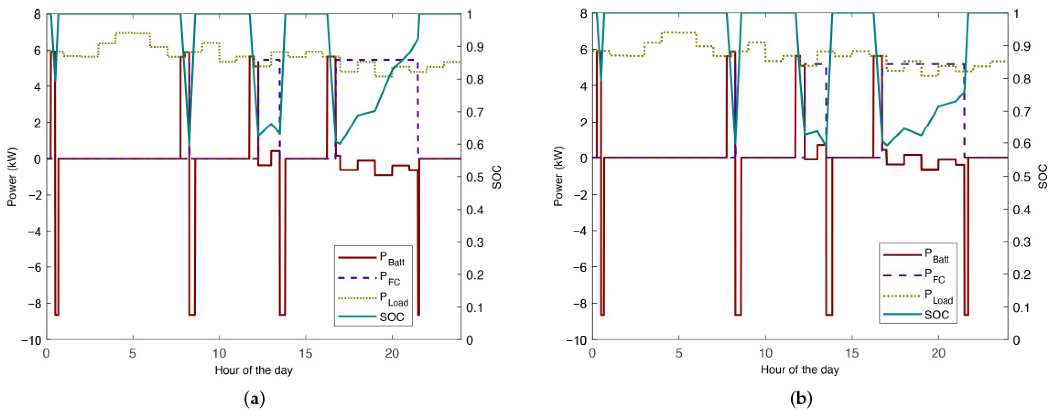
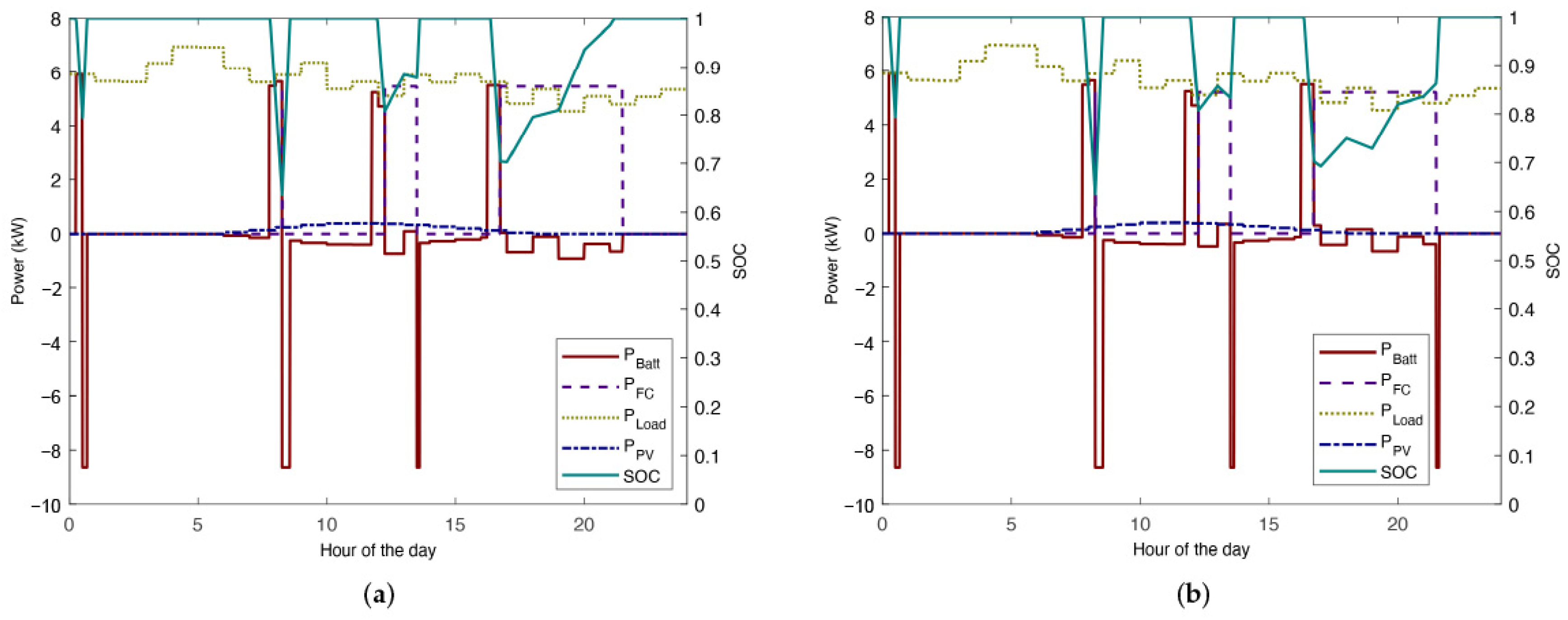
4.1. Possible Daily Scenario

In this section, the following hypothetical power outage distribution was considered for a day in July 2020, which was the worst month of the year in terms of power outages, as can be seen in Figure 1. The duration of power outages for the daily scenario that was considered in this work were as follows:
  • 15 min from 00:15 h to 00:30 h;
  • 30 min from 08:00 h to 08:30 h;
  • 1 h and 30 min from 12:00 h to 13:30 h;
  • 5 h from 16:30 h to 21:30 h.
As previously mentioned, the fuel cell had three different operating points. However, the fuel cell only worked at those three stages when the power demand and power outage duration called for it. The goal of this approach was to avoid the premature degradation of the fuel cell system due to frequent start–stop cycling and operate the fuel cell at constant load during runtimes. Hence, the fuel cell was set to operate at the nominal current density of 0.4 A / cm 2 for the majority of the time, as per the recommendations of the fuel cell manufacturer.

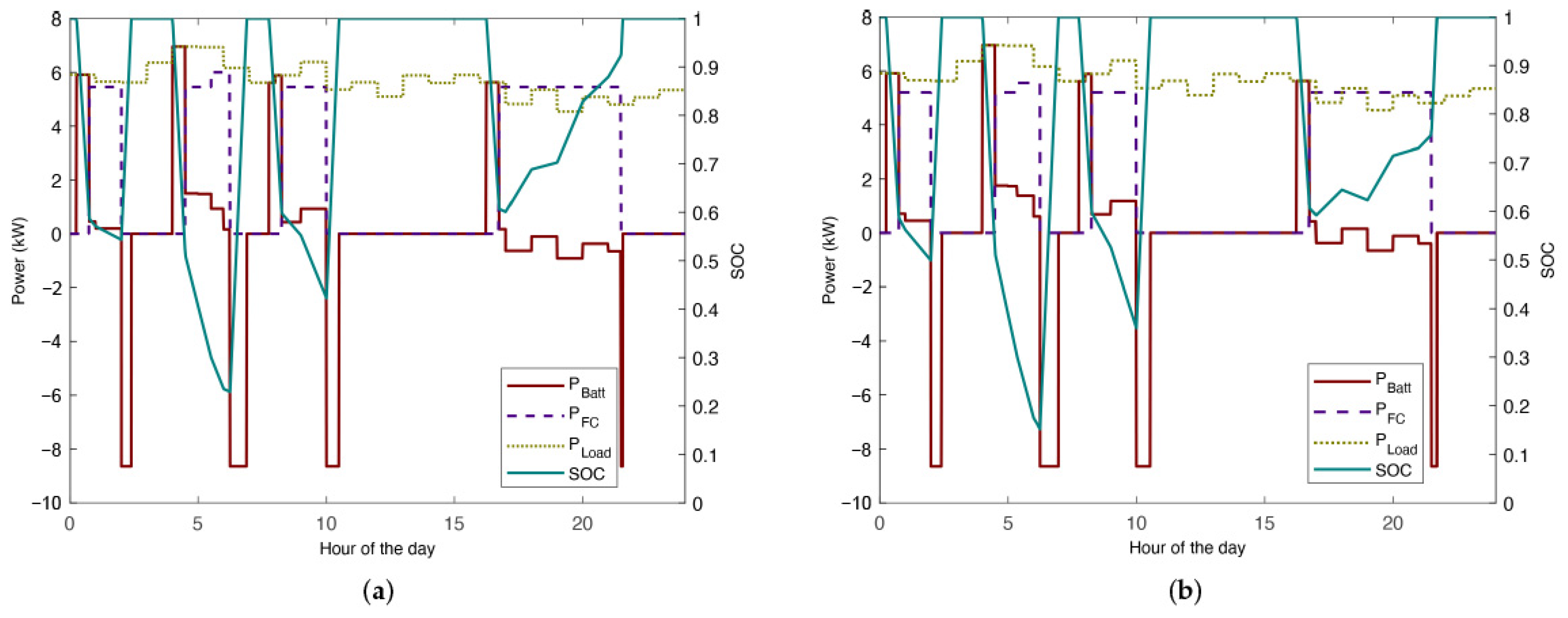
4.1.1. Hybrid System without PV Module

Figure 8 shows the response of the hybrid backup system without PV to the possible daily scenario of power outages, for which the load profile of the telecom tower, the power distribution between the battery and the fuel cell and the battery SOC are presented. The battery SOC reached a minimum value of 60% during the fourth power outage compared to the beginning of life performance of the fuel cell. The fuel cell system was triggered in two out of the four power outages and operated at nominal power. The response of the system was similar after 1000 h of operation and 250 start–stop cycles of the fuel cell.
In Figure 8, it can be seen that only the battery provided power during the first power outage as it was a short power outage and, due to the fuel cell startup time being 30 min, there was no need to turn it on. As soon as the grid power resumed, the battery was recharged up to full capacity, provided that the next outage did not occurs before this was completed. Once the battery was fully charged, only the grid then provided the power that was required by the tower. The negative battery power in the figures implied that the battery was being charged by the grid or the fuel cell, depending on whether there was a power outage or not.
For the second power outage, for which the duration was 30 min, it can be seen that the required load increased from 5.65 kW to 5.9 kW during the power failure and that the battery responded successfully. However, since the power outage lasted longer than 15 min, the reformer turned on. Nonetheless, there was no response from the fuel cell, as can be seen in Figure 8. This was due to the fact that the initial 45 min of every power outage were supplied by the battery alone, as it was assumed that the fuel cell startup would be triggered 15 min after a power outage and it would take 30 min to complete. Therefore, the fuel cell in this case turned on but did not start up as the grid power resumed before it was needed.
For power outages that were longer than 1 h 30 min, it can be seen that the battery supplied the power in the beginning and then, as the outage continued, the fuel cell was turned on for the later stages in both cases until the grid power resumed. In this way, the backup power for the telecom tower was guaranteed by the hybrid system. For the third power outage at 12:00 o’clock, it can be seen that as soon as the fuel cell started to provide power to the system, the energy that was required from the battery decreased. Figure 8 shows that the operating power of the fuel cell was 5.45 kW, the value that was chosen to be the P F C o p t that corresponded to the nominal current density of 0.4 A / cm 2 . As expected, the hybrid system responded similarly to the fourth power outage as well. It can also be seen that the fuel cell recharged the battery when the power that was required by the telecom tower was lower than the fuel cell power output at the given operating point. This is easily noticed in Figure 8, during the interval from 16:45 h to the end of the power outage, for which the SOC line presents multiple negative and positive slopes that demonstrate the discharging and charging stages, respectively.

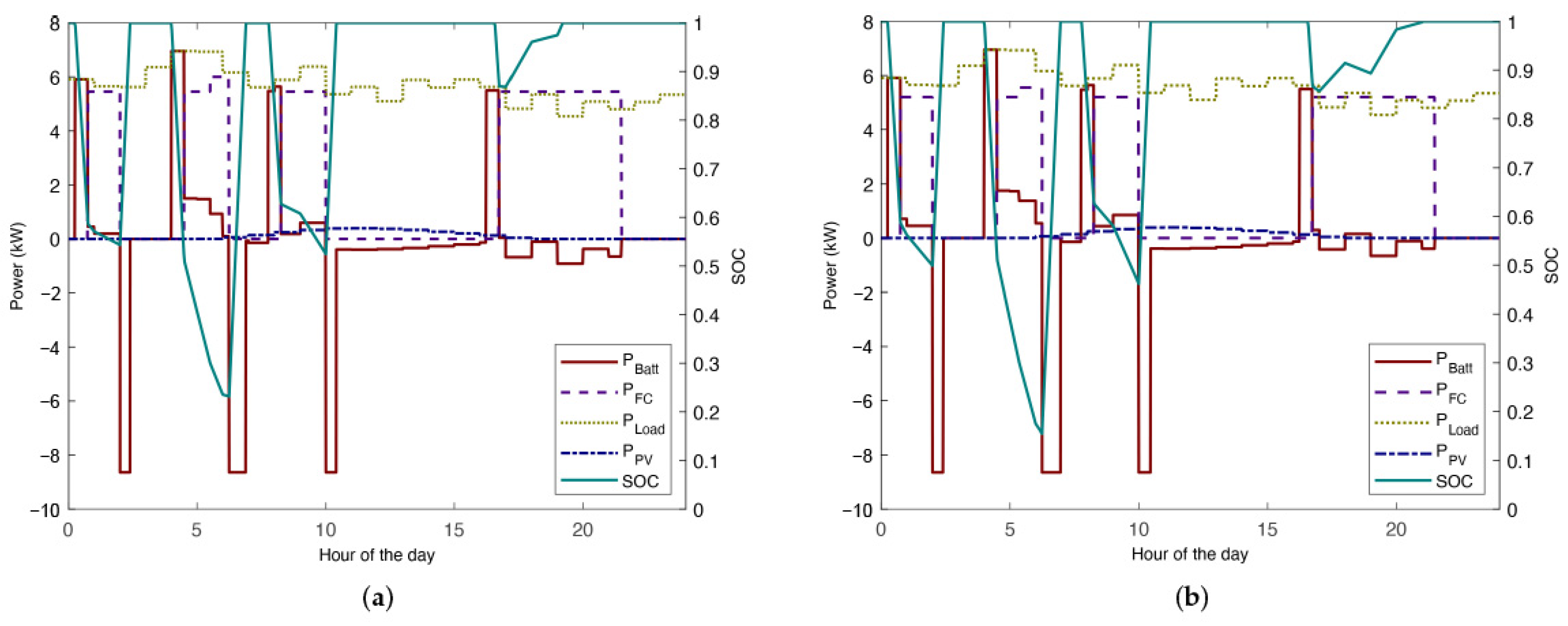
4.1.2. Hybrid System with PV Module

In Figure 9, a substantial difference can be seen in the battery SOC during the fourth power outage, for which the integration of the PV system helped to keep the SOC at 70% compared to around 60% in the case without PV. However, since the direct normal irradiation was low in the early morning, the SOC barely changed for the second power outage at 8 o’clock.
Therefore, it could be concluded that the integration of the PV system provided an extra source of stability when the direct normal irradiation assumed certain values. However, the PV integration only affected the battery SOC directly, which meant that the methanol consumption remained unaltered compared to the consumption in the previous scenarios without PV of around 28.19 L.

4.2. Long Power Outages Scenario

In the previous section, the hybrid system was modeled considering a random daily scenario with four different power outages during the day. To validate the robustness of the hybrid system, another scenario consisting of only longer power outages was also investigated. Four power outages that lasted between 1 h 45 min and 5 h 15 min were considered. Figure 10 and Figure 11 show the response of the hybrid fuel cell–battery system to the long power outages scenario without a PV system and with a PV system, respectively.

4.2.1. Hybrid System without PV Module

In Figure 10, it can be seen that the battery SOC dropped below 30% at around the 6 h mark, both for the beginning of life and end of test performances of the fuel cell. For the first power outage, a considerable reduction in the power that was supplied by the battery could be noticed when the fuel cell was activated. Although the fuel cell became the main power source at this stage, the battery was still required to provide power. A similar trend was seen for the second power outage, but its duration was longer than the first outage. As can be seen in Figure 10, the SOC of the battery decreased to 22% in the case of the BOL performance of the fuel cell and down to 15% after 1000 h and 250 cycles of operation. These values could cause instability through successive interruptions, unless there was enough time to fully charge the battery before the next outage. The battery was required even when the fuel cell power increased from P F C o p t to P F C m a x , which left the system in a precarious situation unless the grid resumed or the load demand of the tower decreased. This problem could be solved at the system design stage by increasing the size of the fuel cell to meet higher power demands.
Similarly, for the fourth power outage (between 16:30 h and 19:30 h) the fuel cell provided the required power and when the load demand was higher than the fuel cell power output, the remainder was covered by the battery. This last power outage had a duration of 5 h and 15 min; nonetheless, the hybrid system could respond well and kept the SOC of the battery at an acceptable value. The response of the hybrid system was better for the longer power outages than for the previous shorter outages. This was because the response of the system depended on the load profile of the tower and hence, on the time of day. As can be seen in Figure 3, the later hours of the day had lower load requirements; therefore, once fully operational, the fuel cell could cover the whole duration of the outage while also recharging the battery.

4.2.2. Hybrid System with PV Module

When adding the PV module into the hybrid system, no remarkable differences could be seen in the battery SOC at 7 o’clock in the morning, as shown in Figure 11. This was due to the low direct normal irradiation at that specific hour. However, during the third and fourth power outages, the PV system improved the capacity of the system considerably, with the SOC increasing from 43% to 53% and from 60% to 88% compared to the system without PV, respectively. Additionally, it could be noticed that the degradation of the fuel cell affected the performance of the hybrid system. In fact, it took the fuel cell around two hours longer to fully charge the battery compared to BOL, as can be seen at around the 17 h mark in Figure 11.
Therefore, it could be concluded that the hybrid system with the integrated PV module had a stable response to power demands of up to 7 kW for the power outage scenarios that were considered. However, if the required load were higher and the power failure were extensive, the system may achieve non-optimal values, such as a low battery SOC. Due to the fact that the behavior of the fuel cell was the same with or without PV module, the methanol consumption for the four long power outages was the same for both cases at around 45.12 L.

5. Discussion

As previously mentioned, the main scope of the model was to extend the lifetime of a hybrid fuel cell–battery system and optimize its fuel consumption. Since fuel cells degrade faster under cyclic operating conditions, especially start–stop cycles and load cycling, this degradation was minimized by only running the fuel cell when strictly needed and by operating it in intervals of steady-state conditions. This was possible in the fuel cell–battery hybrid solution for backup applications because the battery shouldered most of the burden of short power outages and the eventual fluctuations in power consumption. Furthermore, the integration of a PV module could enhance the hybrid system and its impact on the stability of the system was also analyzed.
The majority of investigations in the literature on EMSs for hybrid systems have not been related to stationary applications and PV modules have been rarely considered [22,27,29,30,31,32]. Barelli et al. [29] used a dynamic model of a PEM fuel cell for a hybrid system for bus applications to optimize the sizing of the fuel cell and the battery SOC to respond to a real daily driving load demand. Different algorithms with fixed fuel cell power outputs for hybrid systems can be found in the literature [17,19,32], in which a fuel saving of up to 20% was achieved [19]. Most of these research studies used the fuel cell as the main power source, while batteries and capacitors were used to store and provide energy during the possible fluctuations in the required power [30,31]. In the current work, the main backup power source alternated between the battery and the fuel cell, depending on the duration of the power outage, for which three fuel cell operating points, namely, P F C m i n , P F C o p t and P F C m a x , were defined and controlled by the EMS. The battery pack was used as the main source of power in the beginning of the outages. However, when a power outage extended for longer than 45 min, the fuel cell became the main backup power source and the battery worked as a storage device or provided power when the load fluctuations had peaks that were higher than the output of the fuel cell.
To minimize the degradation of the fuel cell, three constant load operating points were pre-defined. However, it was also important to avoid a low SOC for the battery in order to prevent faster degradation and possible system failure. This called for a proper control strategy for the battery SOC to keep it from reaching low values in the case of the load demand being higher than the fuel cell could provide. Even though it is recommended that the battery SOC is kept above 30% [28], in this work, SOC conditions of below 30% were also considered to allow for a more resilient backup system for longer power outages. In these cases of higher loads and longer power outages, the fuel cell worked at a user-defined constant maximum power. Additionally, although the power output and the efficiency of the fuel cell decreased due to degradation, as shown in Table 3, the hybrid system was adequate for the considered degradation level. In this regard, the application of a PV module with peak power of 400 W showed important advantages for the battery SOC when direct normal radiation was available. However, since the PV did not directly affect the fuel cell operation, this integration did not have any effect on fuel consumption.
When comparing the different scenarios that were investigated in this work, especially the long power outages scenario, it could be noticed that the hybrid system responded better to longer power outages with lower load demands than to shorter outages with higher load demands. Even after 1000 h of operation, the system could handle the load and keep the battery within a good range of SOC, as can be seen in Figure 12. This was because the response of the system depended on the load profile of the telecom tower and hence, on the time of day. This shows that for the stability of a hybrid system that distributes the load demand of a tower between a fuel cell and a battery, high load demands are as critical as longer power outages. This also implies that to increase the robustness of this hybrid system for backup applications, the proper sizing of the a fuel cell with respect to the load demand profile is of paramount importance. Alternatively, integrating PV modules into the hybrid system can increase the stability of the system, especially for daytime operation.
The environmental advantages of the hybrid system, such as the significant reduction in CO2 emissions or the carbon neutral operation when renewable methanol was used, were evident as the system reduced the local emissions of NOx, eliminated SOx emissions and produced no noise. However, another important factor that is worth considering for such a hybrid renewable energy system (HRES) is the cost of installation and operation compared to conventional power sources. Krishnamoorthy and Raj [33] reported that an HRES-based power generation at an off-grid location could be a cost effective solution. They compared hybrid conventional bio-gasifiers to renewable energy systems and standalone renewable energy systems with high renewable fractions to standalone conventional bio-gasifiers and found that a hybrid PV, wind and bio-gen-based HRES system was the best fitted HRES solution for the Korkadu village, Puducherry, India. A more detailed techno-economic analysis of a similar bio-based hybrid system incorporating a PV and different battery technologies can be found in [34] for the same village in India.
Methanol, as with the above-mentioned bio-based fuels, can be produced locally using hydrogen from renewable electricity and CO2 from biomass (a process which is expected to become cost competitive in the near future) or alternatively, through the biomass gasification into methanol pathway, which is already capable of meeting competitive market costs [35]. Therefore, a hybrid system that is based on PV, RMFC and a battery, such as that studied in the current work for backup applications, not only has the aforementioned environmental advantages but also has the potential to be competitive with conventional solutions in terms of total cost of ownership. This is due to the increased reliability and reduced maintenance costs, which are produced by the absence of moving parts, and cost competitive renewable methanol. It is also worth mentioning that even though RMFC technology is still maturing and the durability and cost targets are still not met for some applications, the technology is gaining momentum within the telecom backup sector, for which the durability requirements are less stringent. Moreover, the hybrid configuration in the current work, with a PV and a battery along with the proposed EMS, could increase the durability of an RMFC system and enhance the reliability and availability of the backup power system for telecom services.

6. Conclusions

A hybrid reformed methanol fuel cell–battery system for telecom backup applications was modeled in this study. The interest in using fuel cells and batteries within a hybrid system in which the advantages of both power supplies can be enhanced by each other is expanding due to their advantages of low emissions and no noise compared to traditional diesel generators. In this paper, a rule-based energy management system with 12 different operating conditions was proposed. The battery SOC and the load profile of the telecom tower were used as inputs for the EMS. Additionally, a PV system was integrated in order to compare its effects on the stability of the system. The same daily load profile was used in all of the different scenarios, for which a possible daily scenario with four power outages, which was based on historical data, and a worst case scenario with four long power outages were investigated. Even though the latter scenario was unlikely to happen considering the data from 2020, in which only 3 out of 57 power outages were long during the worst month of the year, the system still responded adequately.
For the long power outages scenario, it was found that the hybrid system responded better to longer power outages with lower load demands compared to shorter outages with higher load demands. Therefore, both the load profile and the duration of the power outage are critical parameters for the stability of hybrid backup systems and should be considered early on in the system design process. Moreover, it was found that a PV module enhanced the performance of the hybrid system for daytime operation by avoiding low battery SOC.
Since the battery acted as the auxiliary power source when the fuel cell was operational and could respond faster to load fluctuations, the slow dynamics of the fuel cell were not considered in the EMS that was developed in this paper. The response of the hybrid backup system to the different scenarios was investigated both for the beginning of life performance of the fuel cell and for the reduced performance of the fuel cell after 1000 h of operation and 250 start–stop cycles. It was found that the system responded well in both cases.
Finally, the methanol consumption was estimated for each scenario. Since the PV module only affected the battery SOC and not the duration of the fuel cell operation, the fuel consumption was not affected by the addition of the PV module into the system. However, it is worth noting that the PV system increased the stability of the system and enhanced battery durability as it avoided low battery SOC.

Author Contributions

Conceptualization, S.S.A., S.L.S., D.L.M. and T.L.B.; methodology, D.L.M., S.S.A. and S.L.S.; software, D.L.M. and S.L.S.; validation, D.L.M. and T.L.B.; formal analysis, D.L.M., S.S.A., S.L.S. and T.L.B.; investigation, D.L.M., S.S.A., S.L.S., V.L., N.L. and T.L.B.; resources, S.S.A. and T.L.B.; data curation, D.L.M., S.S.A. and S.L.S.; writing—original draft preparation, D.L.M. and S.S.A.; writing—review and editing, D.L.M., S.S.A., S.L.S., V.L., N.L. and T.L.B.; visualization, D.L.M. and S.S.A.; supervision, S.S.A. and S.L.S.; project administration, S.S.A. and T.L.B.; funding acquisition, S.S.A. and T.L.B. All authors have read and agreed to the published version of the manuscript.

Funding

This research was funded by the EU regional fund for Energy, Technology, Innovation (ETI) through the Fuel cell bridging battery “Blue+Box” project via CLEAN (grant number RN-18033) and the Danish Energy Technology Development and Demonstration Program (EUDP) through the MFC MultiGen project (grant number 64020-2073).

Institutional Review Board Statement

Not applicable.

Informed Consent Statement

Not applicable.

Data Availability Statement

The data are contained within the article.

Conflicts of Interest

One of the authors, Thomas Leopold Berg, is employed by Blue World Technologies ApS, a company that develops reformed methanol fuel cells. The funders had no role in the design of the study, the collection, analyses or interpretation of data, the writing of the manuscript or the decision to publish the results.

Abbreviations

The following abbreviations are used in this manuscript:
SOCState-of-charge
EMSEnergy management system
PVPhotovoltaic cell
PEM/PEMFCProton exchange membrane fuel cell
HT-PEMFCHigh-temperature proton exchange membrane fuel cell
EOTEnd of test
BOLBeginning of life
DCDirect current

References

  1. 5G Power: Creating a Green Grid That Slashes Costs, Emissions & Energy Use. Available online: https://www.huawei.com/us/technology-insights/publications/huawei-tech/89/5g-power-green-grid-slashes-costs-emissions-energy-use#:~:text=In%20the%205G%20era%2C%20the,configuration%20in%20the%205G%20era (accessed on 8 November 2021).
  2. “5G Will Prompt Energy Consumption to Grow by Staggering 160% in 10 Years”—Datacenter Forum. Available online: https://www.datacenter-forum.com/datacenter-forum/5g-will-prompt-energy-consumption-to-grow-by-staggering-160-in-10-years (accessed on 24 April 2022).
  3. What Is a 5G Cell Tower? Available online: https://www.anscorporate.com/blog/what-is-a-5g-cell-tower (accessed on 26 January 2022).
  4. Ahamed, M.M.; Faruque, S. 5G network coverage planning and analysis of the deployment challenges. Sensors 2021, 21, 6608. [Google Scholar] [CrossRef] [PubMed]
  5. Mobile Subscriptions by Country Worldwide 2019|Statista. Available online: https://0-www-statista-com.brum.beds.ac.uk/statistics/268232/top-10-countries-by-number-of-mobile-cellular-subscriptions/ (accessed on 5 October 2021).
  6. Deevela, N.R.; Singh, B.; Kandpal, T.C. Load profile of telecom towers and potential renewable energy power supply configurations. In Proceedings of the 2018 IEEE International Conference on Power Electronics, Drives and Energy Systems (PEDES), Chennai, India, 18–21 December 2018; pp. 1–6. [Google Scholar]
  7. Gilles, F.; Toth, J.; European Investment Bank; Innovation Finance Advisory. Accelerating the 5G Transition in Europe: How to Boost Investments in Transformative 5G Solutions. Main Report, European Investment Bank, 2021. Available online: https://data.europa.eu/doi/10.2867/252427 (accessed on 24 April 2022).
  8. California Public Utilities Commission Final Analysis Report Reliability Standards for Telecommunications Emergency Backup Power Systems and Emergency Notification Systems F I L E D. 2008. Available online: https://www.cpuc.ca.gov/EFILE/PD/82464.pdf (accessed on 23 February 2022).
  9. U.S. Department of Energy (DOE). Fuel Cells for Backup Power in Telecommunications Facilities (Fact Sheet). April 2009. Available online: www.hydrogen.energy.gov (accessed on 23 February 2022).
  10. Leng, F.; Tan, C.M.; Pecht, M. Effect of Temperature on the Aging rate of Li Ion Battery Operating above Room Temperature. Sci. Rep. 2015, 5, 12967. [Google Scholar] [CrossRef] [PubMed] [Green Version]
  11. Abraham, K. Prospects and limits of energy storage in batteries. J. Phys. Chem. Lett. 2015, 6, 830–844. [Google Scholar] [CrossRef] [PubMed]
  12. Wang, Y.; Chen, K.S.; Mishler, J.; Cho, S.C.; Adroher, X.C. A review of polymer electrolyte membrane fuel cells: Technology, applications, and needs on fundamental research. Appl. Energy 2011, 88, 981–1007. [Google Scholar] [CrossRef] [Green Version]
  13. Ma, Z.; Eichman, J.; Kurtz, J. Fuel cell backup power system for grid service and microgrid in telecommunication applications. J. Energy Resour. Technol. 2019, 141, 062002. [Google Scholar] [CrossRef] [Green Version]
  14. Vasallo, M.J.; Andújar, J.M.; Garcia, C.; Brey, J.J. A methodology for sizing backup fuel-cell/battery hybrid power systems. IEEE Trans. Ind. Electron. 2009, 57, 1964–1975. [Google Scholar] [CrossRef]
  15. Garcia, P.; Fernandez, L.M.; Garcia, C.A.; Jurado, F. Energy Management System of Fuel-Cell-Battery Hybrid Tramway. IEEE Trans. Ind. Electron. 2010, 57, 4013–4023. [Google Scholar] [CrossRef]
  16. Chen, Y.S.; Lin, S.M.; Hong, B.S. Experimental study on a passive fuel cell/battery hybrid power system. Energies 2013, 6, 6413–6422. [Google Scholar] [CrossRef]
  17. Bassam, A.M.; Phillips, A.B.; Turnock, S.R.; Wilson, P.A. An improved energy management strategy for a hybrid fuel cell/battery passenger vessel. Int. J. Hydrogen Energy 2016, 41, 22453–22464. [Google Scholar] [CrossRef] [Green Version]
  18. Motapon, S.N.; Dessaint, L.A.; Al-Haddad, K. A comparative study of energy management schemes for a fuel-cell hybrid emergency power system of more-electric aircraft. IEEE Trans. Ind. Electron. 2013, 61, 1320–1334. [Google Scholar] [CrossRef]
  19. Zhuo, J.; Chakrabarti, C.; Lee, K.; Chang, N.; Vrudhula, S. Maximizing the lifetime of embedded systems powered by fuel cell-battery hybrids. IEEE Trans. Very Large Scale Integr. (VLSI) Syst. 2009, 17, 22–32. [Google Scholar] [CrossRef]
  20. Prayas-ESMI. Available online: http://www.watchyourpower.org/index.php (accessed on 8 November 2021).
  21. Ryan Ahmed. MATLAB/SIMULINK Bible—Udemy. Available online: https://www.udemy.com/course/matlabsimulink-biblego-from-zero-to-hero/ (accessed on 30 November 2021).
  22. Li, X.; Xu, L.; Hua, J.; Lin, X.; Li, J.; Ouyang, M. Power management strategy for vehicular-applied hybrid fuel cell/battery power system. J. Power Sources 2009, 191, 542–549. [Google Scholar] [CrossRef]
  23. Korthauer, R. Lithium-Ion Batteries: Basics and Applications; Springer: Berlin/Heidelberg, Germany, 2018. [Google Scholar]
  24. Barbir, F. PEM Fuel Cells: Theory and Practice (Second Edition); Academic Press: Cambridge, MA, USA, 2013. [Google Scholar]
  25. Sharma, C.; Jain, A. Solar panel mathematical modelling using simulink. Int. J. Eng. Res. Appl. 2014, 4, 67–72. [Google Scholar]
  26. Global Solar Atlas. Available online: https://globalsolaratlas.info/detail?c=26.894822,81.057816,11&a=80.67041,26.757383,80.67041,27.031728,81.443848,27.031728,81.443848,26.757383,80.67041,26.757383&s=26.875531,80.918427&m=site (accessed on 30 November 2021).
  27. Tie, S.F.; Tan, C.W. A review of energy sources and energy management system in electric vehicles. Renew. Sustain. Energy Rev. 2013, 20, 82–102. [Google Scholar] [CrossRef]
  28. Chen, L.; Lü, Z.; Lin, W.; Li, J.; Pan, H. A new state-of-health estimation method for lithium-ion batteries through the intrinsic relationship between ohmic internal resistance and capacity. Measurement 2018, 116, 586–595. [Google Scholar] [CrossRef]
  29. Barelli, L.; Bidini, G.; Ottaviano, A. Optimization of a PEMFC/battery pack power system for a bus application. Appl. Energy 2012, 97, 777–784. [Google Scholar] [CrossRef]
  30. Chao, C.H.; Shieh, J.J. A new control strategy for hybrid fuel cell-battery power systems with improved efficiency. Int. J. Hydrogen Energy 2012, 37, 13141–13146. [Google Scholar] [CrossRef]
  31. Thounthong, P.; Raël, S.; Davat, B. Energy management of fuel cell/battery/supercapacitor hybrid power source for vehicle applications. J. Power Sources 2009, 193, 376–385. [Google Scholar] [CrossRef]
  32. Han, J.; Charpentier, J.F.; Tang, T. An energy management system of a fuel cell/battery hybrid boat. Energies 2014, 7, 2799–2820. [Google Scholar] [CrossRef] [Green Version]
  33. Krishnamoorthy, M.; Raj, P.A.D. Optimum design and analysis of HRES for rural electrification: A case study of Korkadu district. Soft Comput. 2020, 24, 13051–13068. [Google Scholar] [CrossRef]
  34. Krishnamoorthy, M.; Periyanayagam, A.D.R.; Kumar, C.S.; Kumar, B.P.; Srinivasan, S.; Kathiravan, P. Optimal Sizing, Selection, and Techno-Economic Analysis of Battery Storage for PV/BG-based Hybrid Rural Electrification System. AHEAD-OF-PRINT. IETE J. Res. 2020, 1–16. [Google Scholar] [CrossRef]
  35. Harris, K.; Grim, R.G.; Tao, L. A Comparative Techno-Economic Analysis of Renewable Methanol Synthesis Pathways from Biomass and CO2 Preprint; NREL/CP-5100-78547; National Renewable Energy Laboratory: Golden, CO, USA, 2021. [Google Scholar]
Figure 1. Number of power outages per month in 2020 in Kapoorthla, Lucknow, India. Data from [20].
Energies 15 03218 g001
Figure 2. Power outage duration in July 2020 in Kapoorthla, Lucknow, India. Data from [20].
Energies 15 03218 g002
Figure 3. Hourly load profile of an outdoor base transceiver station, based on data from reference [6]. The values were increased by 2.7 kW to suit more demanding telecom towers.
Energies 15 03218 g003
Figure 4. A schematic of the entire hybrid system for backup telecom applications.
Energies 15 03218 g004
Figure 5. The algorithm of the operation strategy of the EMS for the hybrid system on which the MATLAB model was based.
Energies 15 03218 g005
Figure 6. Averaged polarization curve per cell at BOL and after 1000 h of operation and 250 start–stop cycles (EOT).
Energies 15 03218 g006
Figure 7. Average direct normal irradiation for each day in July in Lucknow, India. Data from [26].
Energies 15 03218 g007
Figure 8. Response of the hybrid system without PV to the daily scenario: (a) beginning of life; (b) after 1000 h of operation and 250 start–stop cycles.
Energies 15 03218 g008
Figure 9. Response of the system with PV to the daily scenario: (a) beginning of life; (b) after 1000 h of operation and 250 start–stop cycles.
Energies 15 03218 g009
Figure 10. Response of the hybrid system without PV to the long power outages scenario: (a) beginning of life; (b) after 1000 h of operation and 250 start–stop cycles.
Energies 15 03218 g010
Figure 11. Response of the hybrid system with PV to the long power outages scenario; (a) beginning of life; (b) after 1000 h of operation and 250 start–stop cycles.
Energies 15 03218 g011
Figure 12. Details of the response of the hybrid system without PV to the long power outages scenario between 4 pm and 11 pm: (a) beginning of life; (b) after 1000 h of operation and 250 start–stop cycles.
Energies 15 03218 g012
Table 1. Specifications of the hybrid fuel cell–battery system.
ParametersValueUnit
Number of Cells in the Fuel Cell Stack75-
P F C o p t 5.455kW
P F C m i n 3.5kW
P F C m a x 6kW
Active Area of the Fuel Cell0.2975m 2
Battery ( c h a r g i n g g r i d ) 8.640kW
Anode Stoichiometric Ratio1.3-
Initial SOC1-
Table 2. Overview of the proposed energy management system.
Battery SOCRequired Backup Power P backup Required Fuel Cell Power (P FC )
S O C < 0.3 P b a c k u p ≤ P F C m i n P F C m a x
P F C m i n < P b a c k u p ≤ P F C o p t P F C m a x
P F C o p t < P b a c k u p ≤ P F C m a x P F C m a x
P b a c k u p > P F C m a x P F C m a x
0.3 < S O C < 0.8 P b a c k u p ≤ P F C m i n P F C o p t
P F C m i n < P b a c k u p ≤ P F C o p t P F C o p t
P F C o p t < P b a c k u p ≤ P F C m a x P F C o p t
P b a c k u p > P F C m a x P F C o p t
S O C > 0.8P b a c k u p ≤ P F C m i n P F C m i n
P F C m i n < P b a c k u p ≤ P F C o p t P F C o p t
P F C o p t < P b a c k u p ≤ P F C m a x P F C o p t
P b a c k u p > P F C m a x P F C o p t
Table 3. Overview of operating parameters at the BOL and EOT of the fuel cell, where i i represents the operating current density and η i the efficiency of the fuel cell. The efficiency was calculated using the higher heating value, HHV.
ParametersBOLEOTUnit
P F C m i n 3.5003.483kW
P F C o p t 5.4555.198kW
P F C m a x 6.0005.647kW
i m i n 0.2400.240A/cm 2
i o p t 0.4000.400A/cm 2
i m a x 0.45660.4566A/cm 2
η m i n 53.0252.03%
η o p t 49.1946.55%
η m a x 47.7544.34%
Publisher’s Note: MDPI stays neutral with regard to jurisdictional claims in published maps and institutional affiliations.

