
Effect of Baffle Dimensionless Size Factor on the Performance of Proton Exchange Membrane Fuel Cell


1
Hubei Key Laboratory of Advanced Technology for Automotive Components, Wuhan University of Technology, Wuhan 430070, China
2
Hubei Collaborative Innovation Center for Automotive Components Technology, Wuhan University of Technology, Wuhan 430070, China
3
School of Automotive Engineering, Wuhan University of Technology, Wuhan 430070, China
*
Author to whom correspondence should be addressed.
Energies 2022, 15(10), 3812; https://0-doi-org.brum.beds.ac.uk/10.3390/en15103812
Submission received: 20 April 2022
/
Revised: 18 May 2022
/
Accepted: 20 May 2022
/
Published: 22 May 2022
(This article belongs to the Special Issue Advanced Techniques for Thermoelectric Generator and Fuel Cell System)
Abstract
:In this paper, the model of a proton exchange membrane fuel cell (PEMFC) with single straight channel is established to investigate the effect of dimensionless size factor of baffles on PEMFC performance. The influence of dimensionless length and height of baffles is discussed. Results show that adding baffles could dramatically optimize the mass transfer in PEMFC. The dimensionless length and height of the baffle have much influence on PEMFC performance.
1. Introduction
With the advantages of high performance, environment-friendly, and energy-saving, PEMFC is popular in lots of fields, such as vehicles, aerospace, and portable electricity supply. However, high-output power density and long duration of vehicular PEMFCs often lead to reactant starvation and water flood. Researchers have studied the factors influencing PEMFC performance under high current density [1,2,3,4,5,6,7]. A major challenge in the commercialization of PEMFC is to improve its mass transfer.
Water accumulation in cathodes is one major issue which needs to be solved. Some researchers used the visualization method and studied the droplet and water transfer in the channel [8,9,10,11]. Chen et al. analyzed motions of liquid water droplets considering inertial force impact [12].
Researchers also found that the optimization of the channel structure could improve the mass transfer [13,14,15,16,17,18,19]. Anyanwu et al. [20] proposed a sinusoidal channel to increase the droplet removal rate. Lei et al. [21] found that cathode channels with tapered slope structures could enhance the turbulence of airflow and improve oxygen concentration in the cathode. Baz et al. [22] designed a new serpentine flow field to optimize reactant transfer and reduce the liquid water saturation.
There are also many researchers focusing on novel flow fields [23,24]. Fahruddin et al. [25] proposed a leaf flow-field with different baffles inserted into the mother channel and found that the beam-shaped baffles could improve the performance. Liu et al. [26] studied the symmetric and asymmetric leaf veins flow channel and found that PEMFC with asymmetric bionic channels performs better. Kang et al. [27] investigated leaf-like flow fields. Results showed that the ginkgo pattern performs better. Chen et al. [28] found that large amplitude and short wavelength in the wave parallel flow fields can improve the PEMFC output power.
Some researchers find that setting baffles in the channel could enhance mass transfer due to the generation of a nozzle-type effect [29]. The size, shape, number, location, and arrangement of baffles are studied to increase the performance and durability of the PEMFC [30,31,32,33]. Wang et al. [34] proposed a novel dot matrix flow-field which could increase the PEMFC performance. Yin et al. [35] and He et al. [36] found that flow fields with baffles increase PEMFC performance. Guo et al. [37] compared the water managements in channels with different baffles and found that baffles in the channel help to remove liquid water more efficiently.
Researchers have found that the size of baffles has a great effect on PEMFC performance. However, most works focus on the actual physical size of baffles. In previous research on baffle shapes [36], it has been revealed that the dimensionless length and height of the baffle could explore the mass transfer enhancement mechanism more specifically than the actual physical size of baffles could. This study aims to explore the effect of dimensionless size of baffle on PEMFC performance and make baffle design quicker and more proper. In this paper, conclusions of relationship between dimensionless size and cell performance are put forward. Experiments are also carried out to validate conclusions.
2. Numerical Models
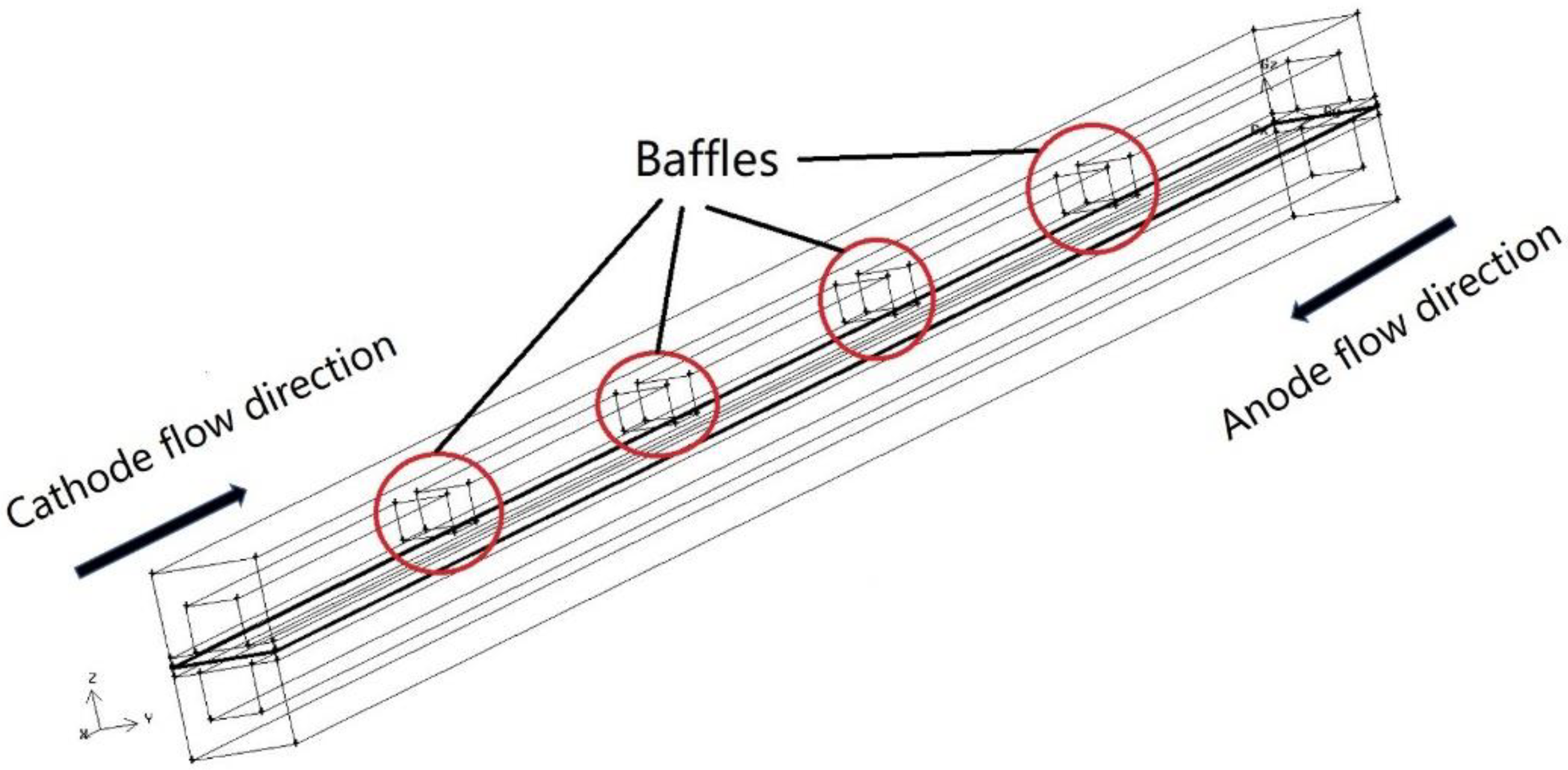
Figure 1 shows the schematic of one of the computational models studied. However, the number of baffles changes with the change of dimensionless length of baffles. Geometric parameters of the computational model are shown in Table 1. The cross-section shape of baffles investigated is set to rectangle.
Cathode inlet direction and anode inlet direction are opposite. Operating conditions are shown in Table 2. Computational governing equations are shown as below [38,39]:
where , , , and stand for porosity, density, mass source, and velocity vector.
where , , and are momentum source, dynamic viscosity, and pressure.
where , , , and are temperature, specific heat capacity, energy source, and effective thermal conductivity.
where , , , and are species effective diffusion coefficient, species concentration, species code, and species source.
where , , ,, γ, and α are local molar concentration for specie , over potential, reference volumetric exchange current density, reference molar concentration for specie , concentration index, and transfer coefficient.
where Ф, σ, S, and subscripts m and e are local potential, electric conductivity, current source, membrane, and electron.
3. Experimental Procedure
4. Results and Discussion
The baseline case is conventional straight channel without baffle. Cases with different dimensionless heights and length of the baffles are discussed below.
4.1. Dimensionless Height of the Baffle
Detailed parameters of different cases are shown in Table 4. Case 1 stands for the conventional straight channel without baffle and is considered as reference case. Case 2 to Case 5 stand for models with height of the baffles set to 50%, 70%, 90%, and 94% of the channel height, respectively.
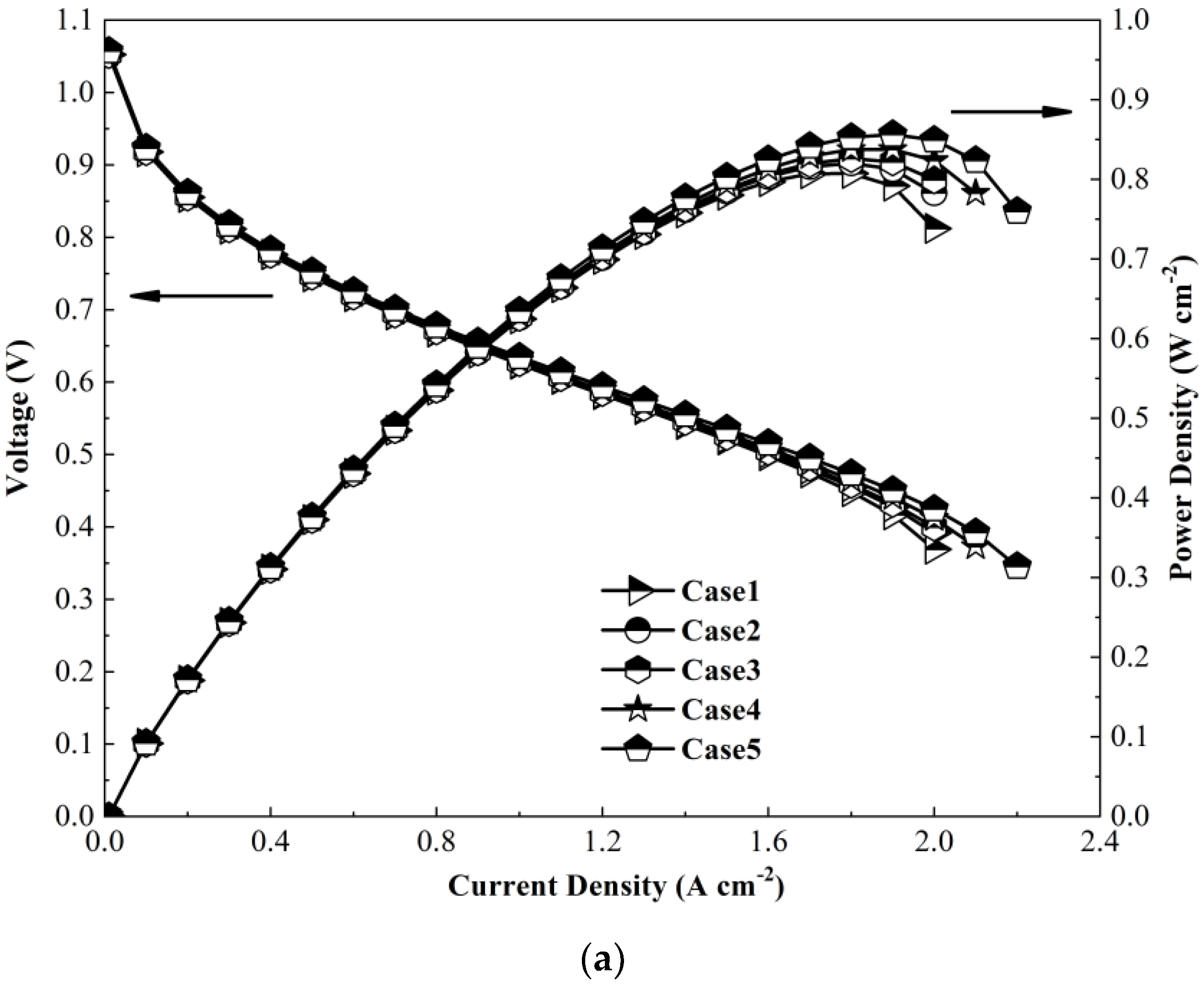
Figure 4a shows polarization curves and gross power curves of different cases. It can be seen that difference of performance among cases is unobvious when current density is below 1.4 A·cm−2. With the increase of the current density, difference of performance becomes apparent when the current density is greater than 1.4 A·cm−2. It is obvious that performance of PEMFC increases with the increase of the dimensionless height of the baffle.
Case 1 obtains the maximum power density when current density is about 1.7 A·cm−2. The current densities under the maximum power density of Case 2 to Case 5 gradually increase from about 1.75 A·cm−2 to about 2.0 A·cm−2. It can be found that increasing the dimensionless height of the baffle in the cathode channel could increase the effective operating current density range and obtain a higher maximum current density of PEMFC.
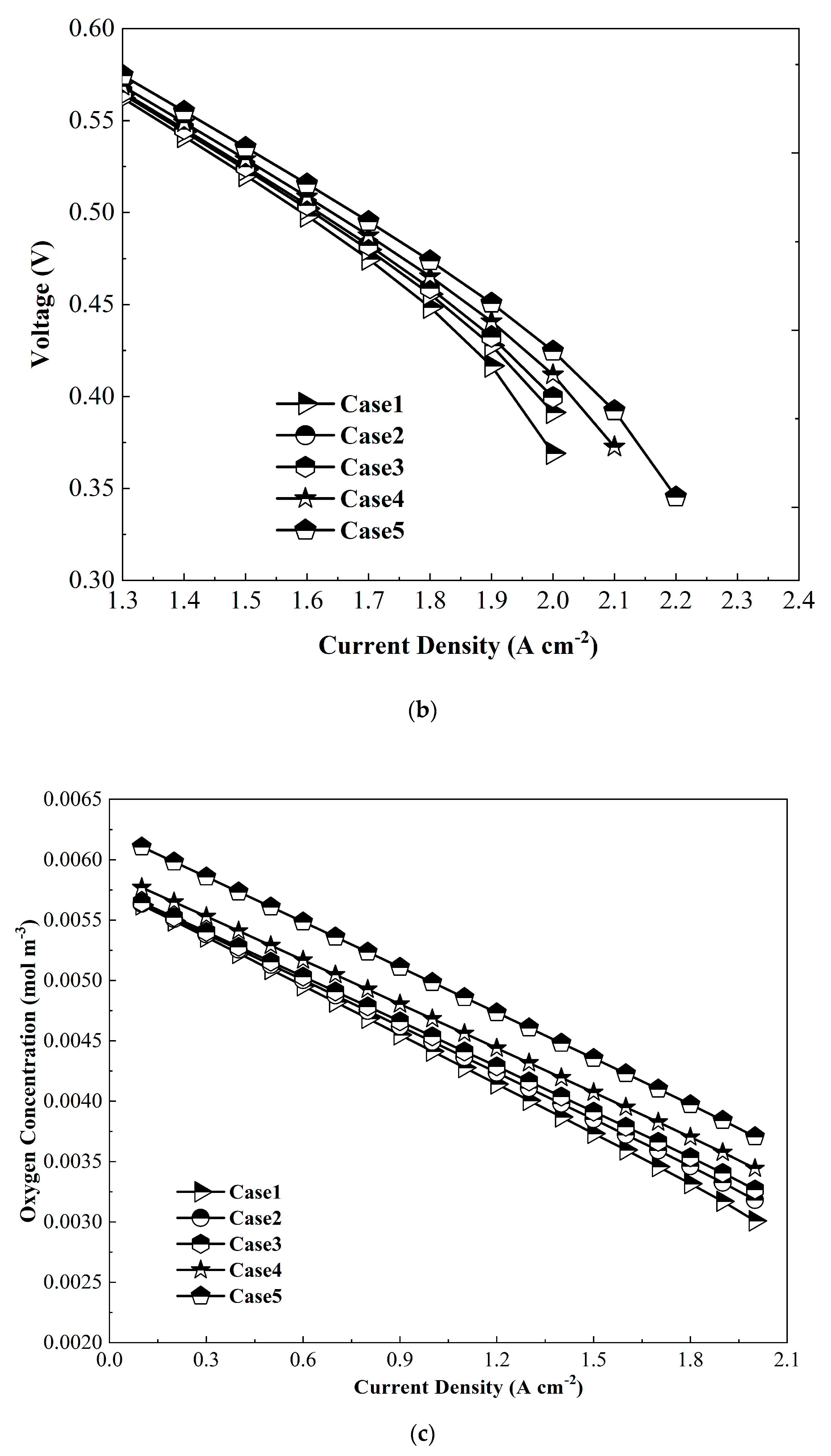
Figure 4b shows the partially enlarged polarization curves of different cases. The activation and ohmic loss of all cases differ a little. However, the concentration polarizations of all cases differ a lot. Cases with baffles could enhance the mass transfer, thus reducing the concentration polarization. The higher the dimensionless height of the baffle, the lower the concentration polarization.
Figure 4c shows the average oxygen molar concentrations between gas diffusion layer (GDL) and catalyst layer (CL) under the different current densities of all cases. The oxygen concentration decreases with the increase of the current density due to the increase of oxygen consumption along the increase of current density. However, the molar concentration raises with the increase of the dimensionless height of the baffle. The raise is more obvious under a higher current density. The concentration difference increases dramatically when the dimensionless height of the baffle is greater than 90%. Baffles in the channel help to improve the pressure inside the channel and speed the mass transfer from channel to GDL, thus enhancing mass transfer in GDL under ribs.
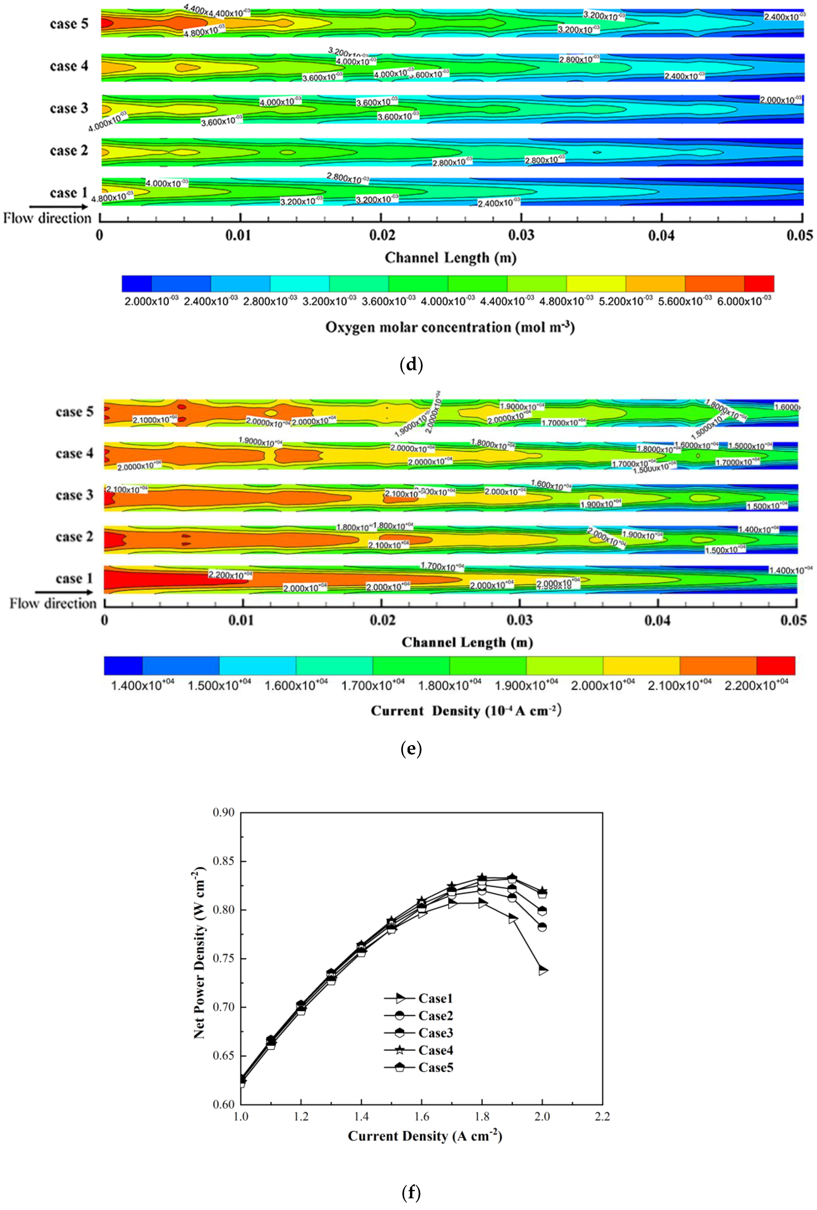
Figure 4d shows contours of oxygen molar concentration between GDL and CL of all cases at the current density set to 1.9 A∙cm−2. It can be seen that the concentration difference is apparent. With the dimensionless height of the baffle increasing, the oxygen molar concentration increases and distributes more evenly both along the channel and normal to the channel direction. It can be found that increasing the dimensionless height of the baffle could optimize the mass transfer of oxygen inside the channel and GDL, especially areas under ribs. The higher the dimensionless height of the baffle is, the more the mass transfer is improved.
It can be concluded that adding baffles could dramatically enhance the mass transfer inside the channel, GDL and CL, and the oxygen could be replenished in time. Adding baffles could alleviate the concentration polarization to some extent.
Figure 4e shows contours of the current density distribution in the middle of GDL of all cases at the current density set to 1.9 A∙cm−2. It is apparent that the gradient of the current density in Case 1 varies more greatly than cases with baffles. The gradient difference of the current density distribution decreases with the increase of the dimensionless height of the baffle since higher baffles lead to higher pressure and more even oxygen distribution in the channel.
Figure 4f shows net power densities of different cases. Table 5 shows power densities at the current density set to 1.9 A cm−2 of all cases and percentage increase compared with Case 1. It can be seen that compared with Case 1, gross power density increases with the dimensionless height of the baffle, while the net power density shows the different trend when the dimensionless height of the baffle height is more than 90% of channel height because of the excessive pumping power. Though the gross power density of Case 5 is higher than other cases, net power density of Case 4 is the highest of the cases. That is, the result of pumping power in Case 5 is excessive compared with other cases. The net power enhancement ratio reaches the maximum value 5.24% when the height of the baffle is 90% of the channel.
4.2. Dimensionless Length of the Baffle
4.2.1. Total Dimensionless Length of Baffles
The ratio of the total length of all baffles inside the channel to the length of channel is discussed as the total dimensionless length of baffles. Case 1 stands for the conventional straight channel without baffles and is considered as reference case. Case 6 to Case 10 stand for models with the total length of the baffle set to 10.8%, 21.6%, 32.4%, 37.8%, and 43.2% of the channel length, respectively. Detailed parameters of different cases are shown in Table 6.
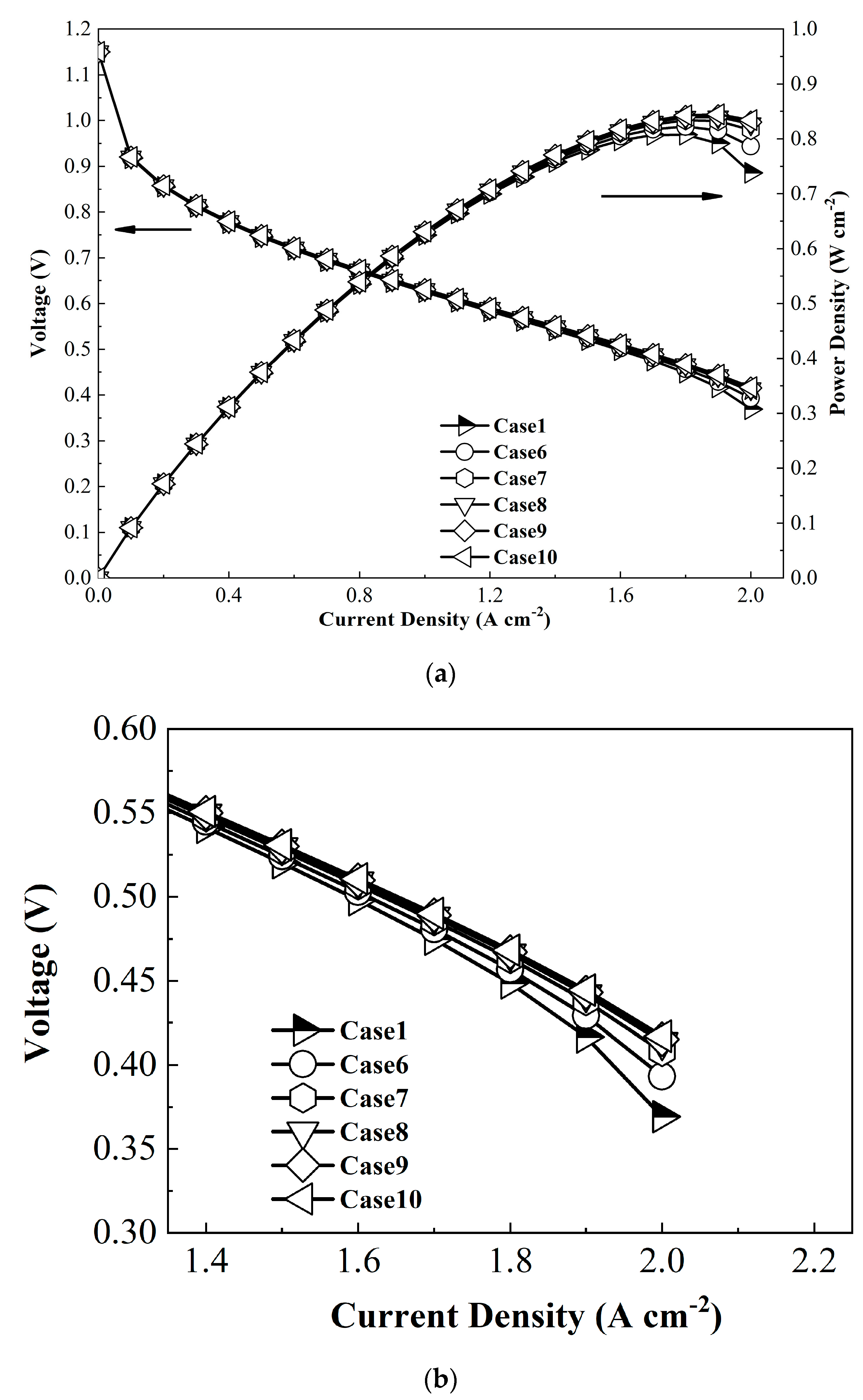
Figure 5a shows that the performance of PEMFC increases with the increase of the total dimensionless length of baffles. It also can be found that increasing the total dimensionless length of baffles in the cathode channel would raise the effective operating current density range and obtain a higher maximum current density of PEMFC. Figure 5b shows the partially enlarged polarization curves of different cases. The activation and ohmic loss of all cases differ a little. However, the concentration polarizations of cases with baffles also differ a little. Figure 5c shows the average oxygen molar concentration between GDL and CL under different current densities of all cases. The oxygen concentration decreases when the current density increases due to the increasing of oxygen consumption at a higher current density. Increasing the total dimensionless length of baffles could dramatically increase the average oxygen molar concentration.
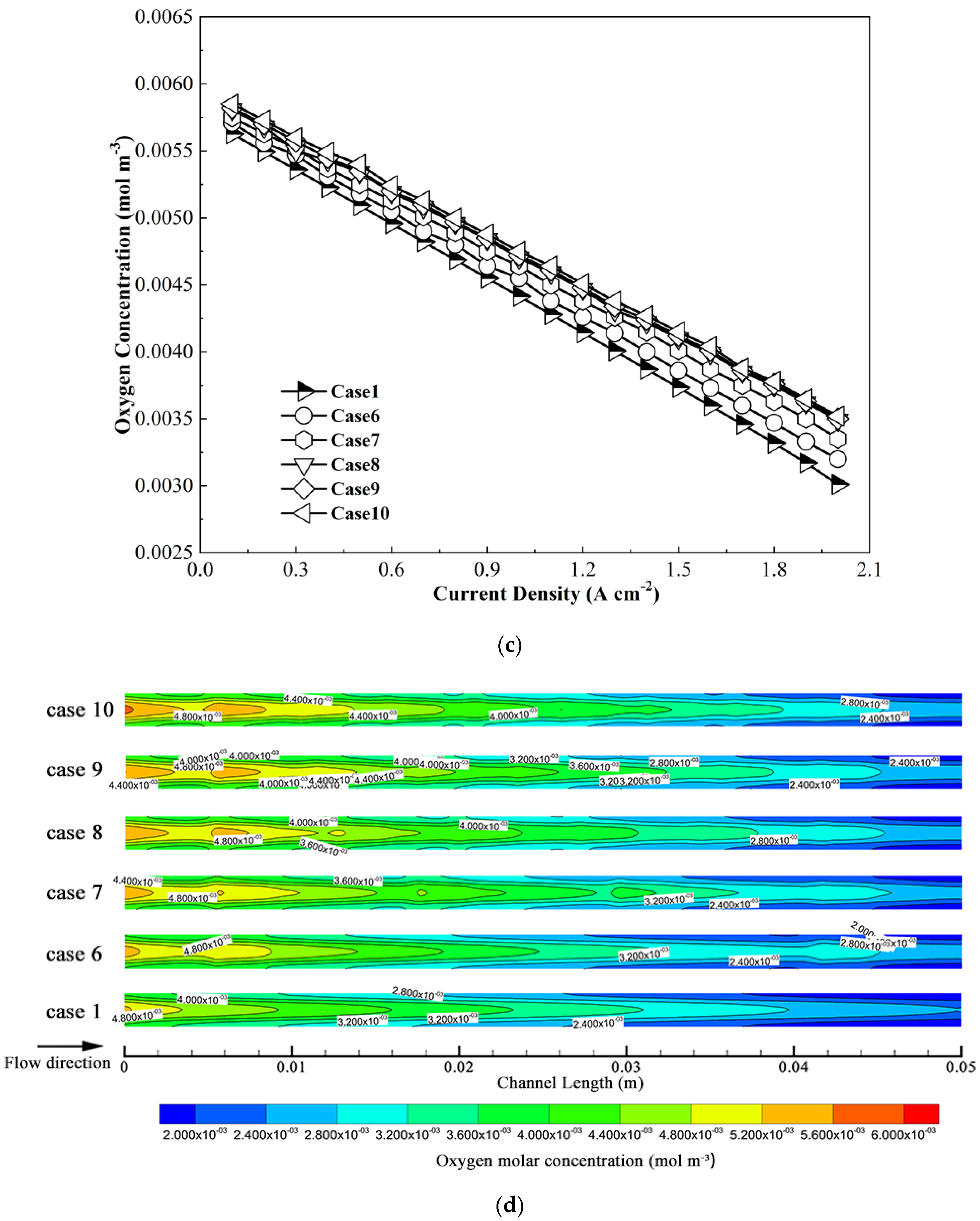
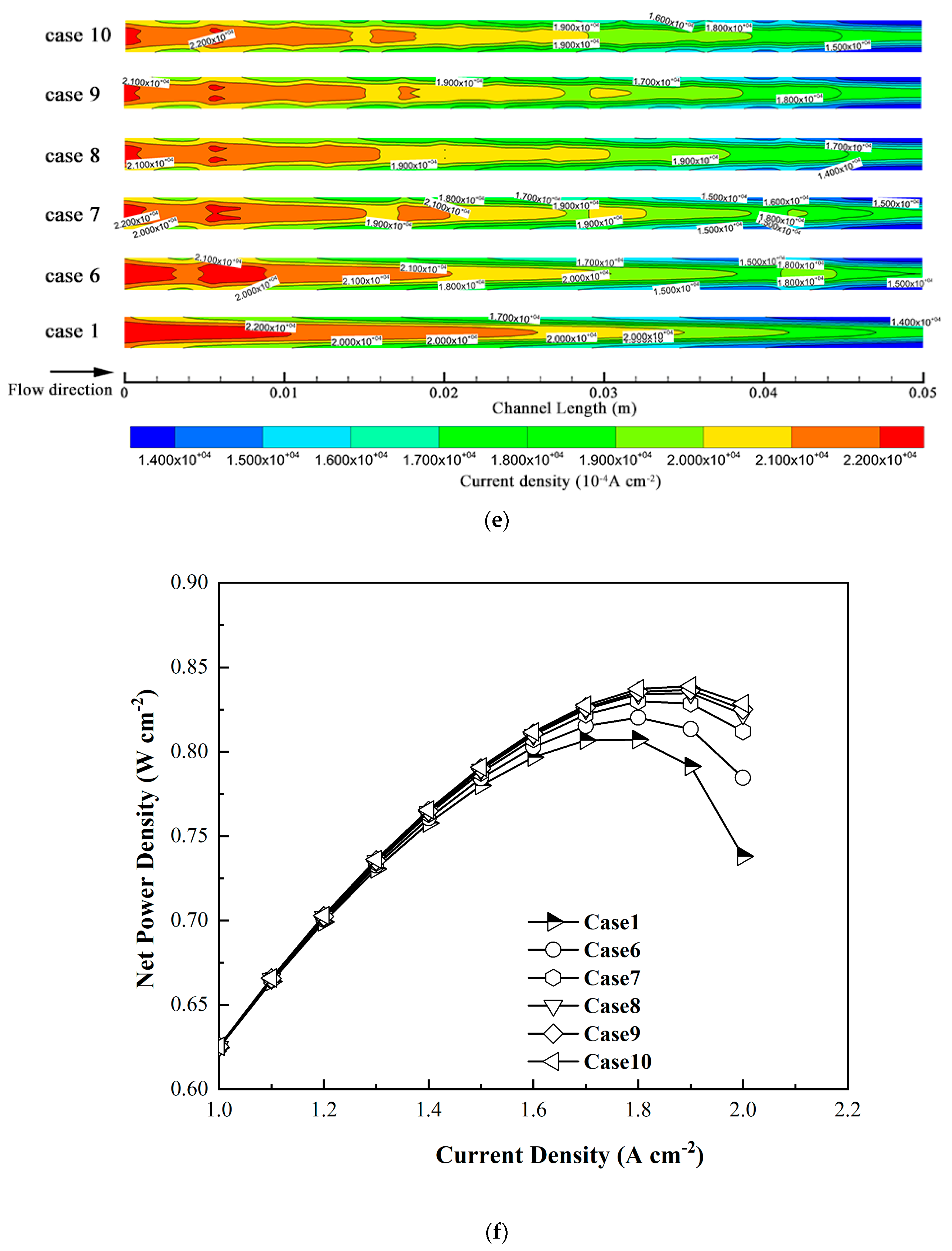
Figure 5c shows that with the increase of total dimensionless length of baffles, the oxygen distributes more evenly both along the channel and normal to the channel direction. Figure 5d shows contours of the current density distribution in the middle of GDL of all cases at the current density set to 1.9 A∙cm−2. Compared to Case 1, cases with baffles obtain more even current density distribution. The distribution difference among cases become unobvious when the total dimensionless length of baffles is greater than 21.6%. Figure 5e shows net power densities of cases with different total length of baffles. Table 7 shows the influence of the total dimensionless length of baffles on the power density at the current density set to 1.9 A∙cm−2. It can be seen that the pumping power density increases with the total length of baffles, and the net power density shows the same trend. Enhancement of net power density increases more slowly with the increase of total length of the baffle compared with gross power density. The net power enhancement ratio reaches the maximum value of 6.01% when the total length of baffles is 43.2% of the channel.
4.2.2. Dimensionless Length of the Single Baffle
The ratio of the length of a single baffle inside the channel to the length of the channel is discussed as the dimensionless length of the single baffle to further study the impact of the dimensionless length of baffles.
The dimensionless length of the single baffle is set to 3.6% and 7.2% in Case 11 and Case 12, respectively, while the total length of baffles and height of the baffle are set to 43.2% and 90% according to the discussion above. Detailed parameters of different cases are shown in Table 8.
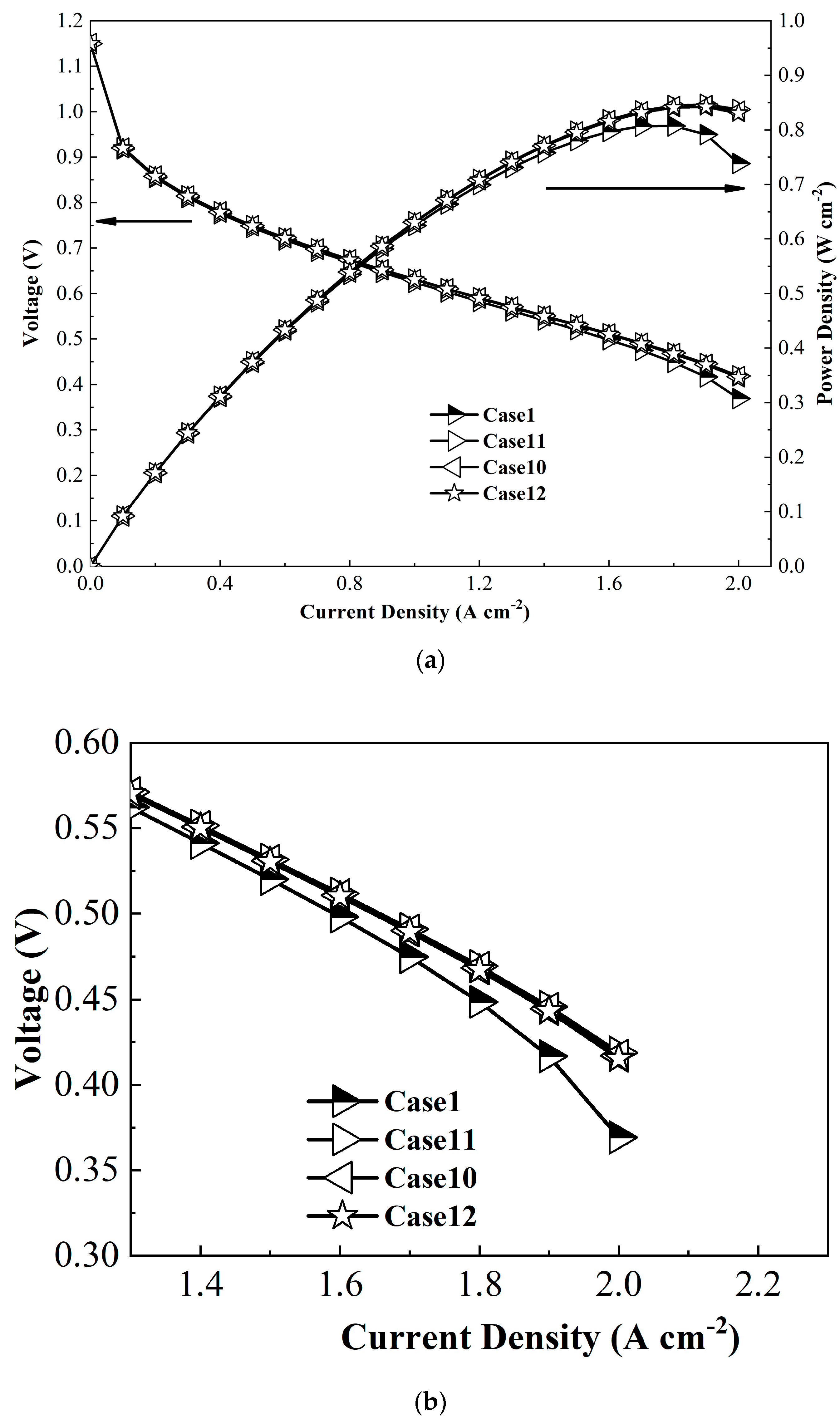
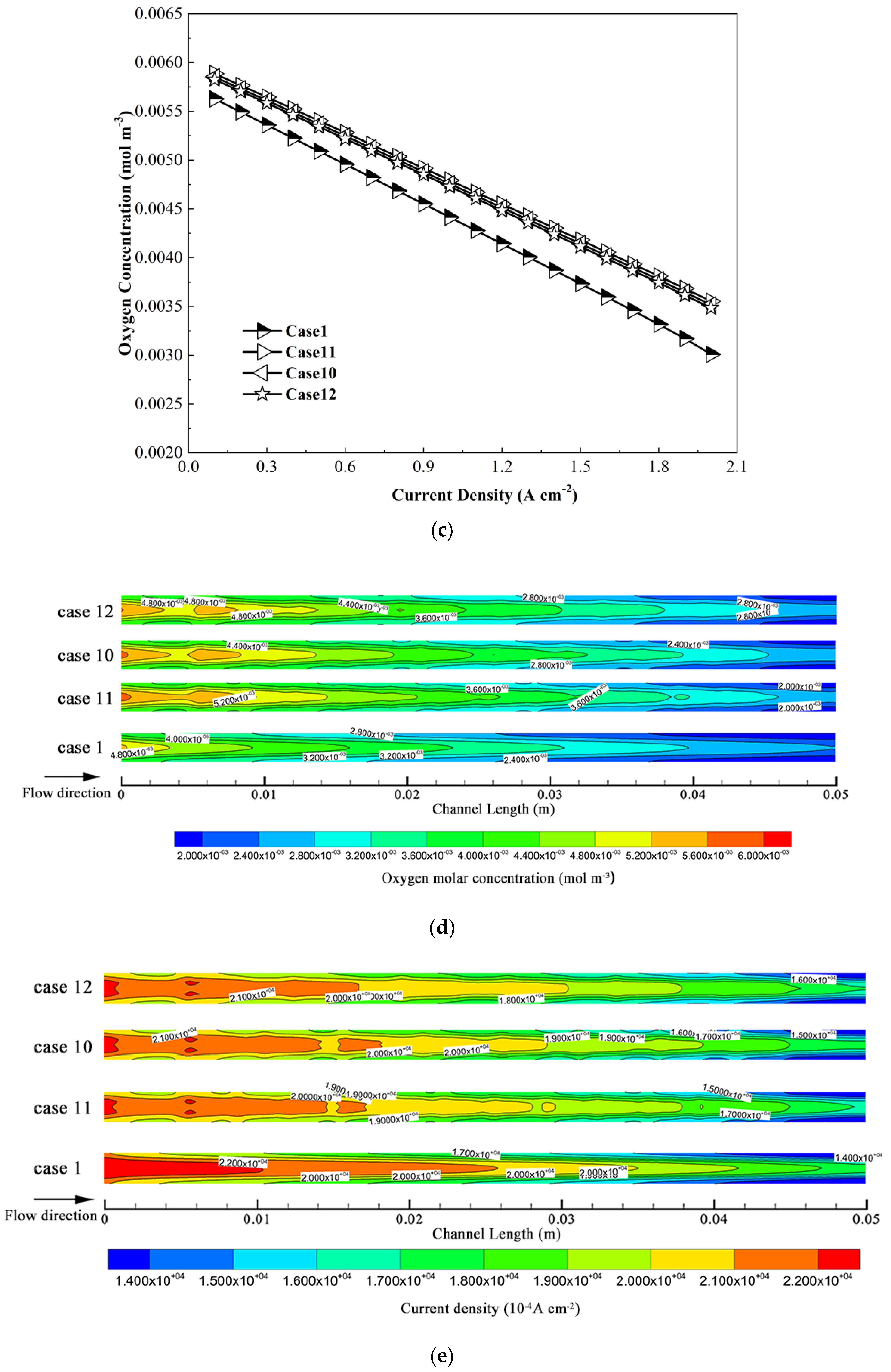
Figure 6a shows polarization curves and gross power curves of different cases. It can be seen that adding baffles could dramatically increase PEMFC performance when current density is high. However, the dimensionless length change of the single baffle has a little impact on PEMFC performance. Figure 6b shows the partially enlarged polarization curves of different cases. The activation and ohmic loss of all cases differ a little. However, the concentration polarizations of cases with baffles differ a little. Figure 6c shows the average oxygen molar concentration between GDL and CL under different current densities of all cases. It can be seen that adding baffles could greatly improve the mass transfer of oxygen. Although the smallest dimensionless length of the single baffle obtains the best performance, the concentration difference among the cases is tiny.
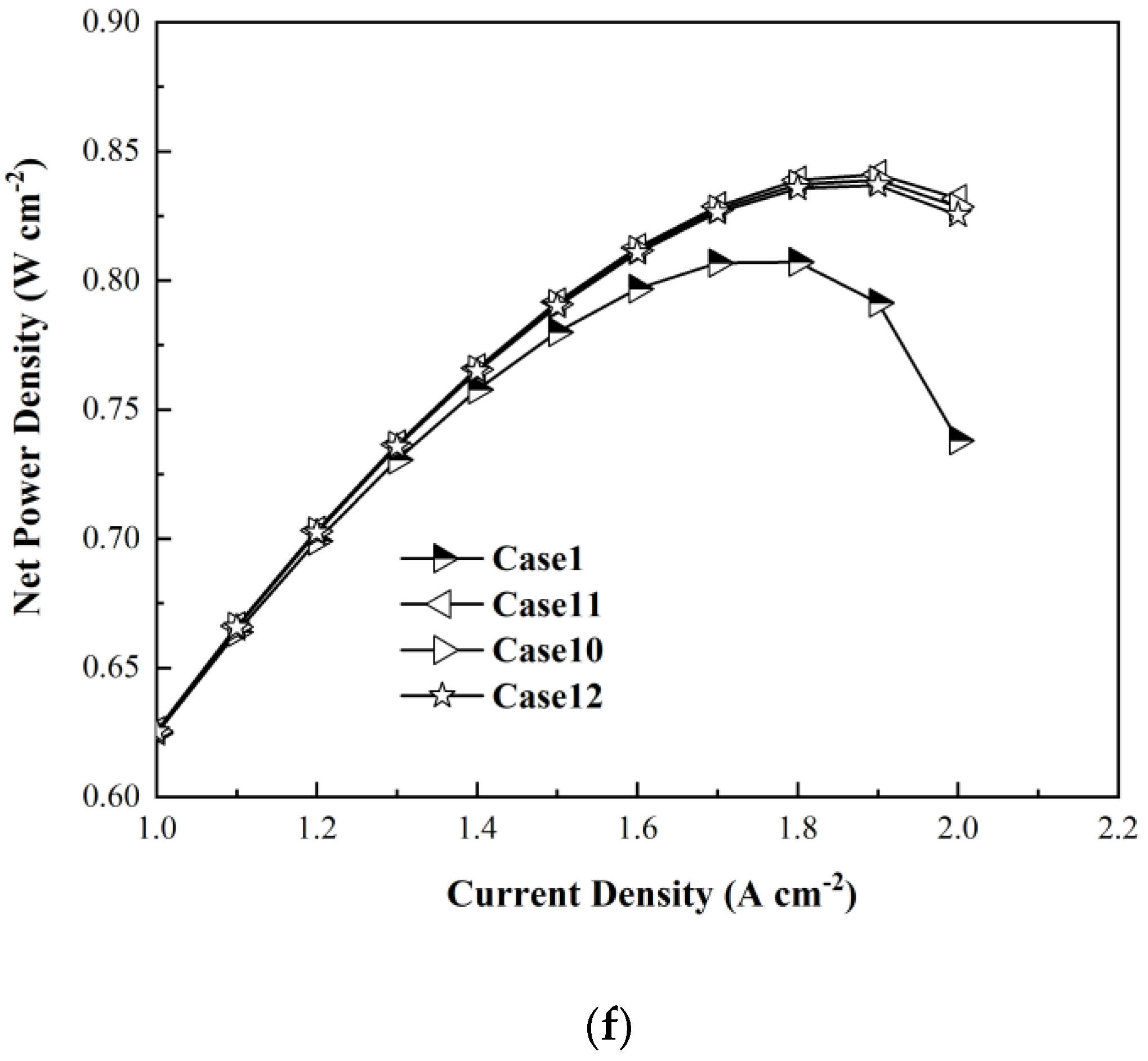
Figure 6d,e show contours of oxygen molar concentration between GDL and CL and the current density distribution in the middle of the GDL of all cases at the current density set to 1.9 A∙cm−2. Similar to the trend above, the smallest dimensionless length of the single baffle obtains the most even current density distribution, but the oxygen concentration difference among the cases is not obvious. Figure 6f shows the net power densities of cases with different length of the single baffle. Table 9 summarizes the influence of the dimensionless length of the single baffle on the power density at the current density set to 1.9 A∙cm−2. Although pumping power decreases along the length of the single baffle, it can be seen that the net power density shows the same trend as gross power. However, the difference between different cases with different dimensionless lengths of the single baffle is not obvious. When the length of the single baffle is set to 3.6% of the channel, the PEMFC net power density could be increased by 6.29%, which is higher than a previous study [37].
4.3. Experimental Validation
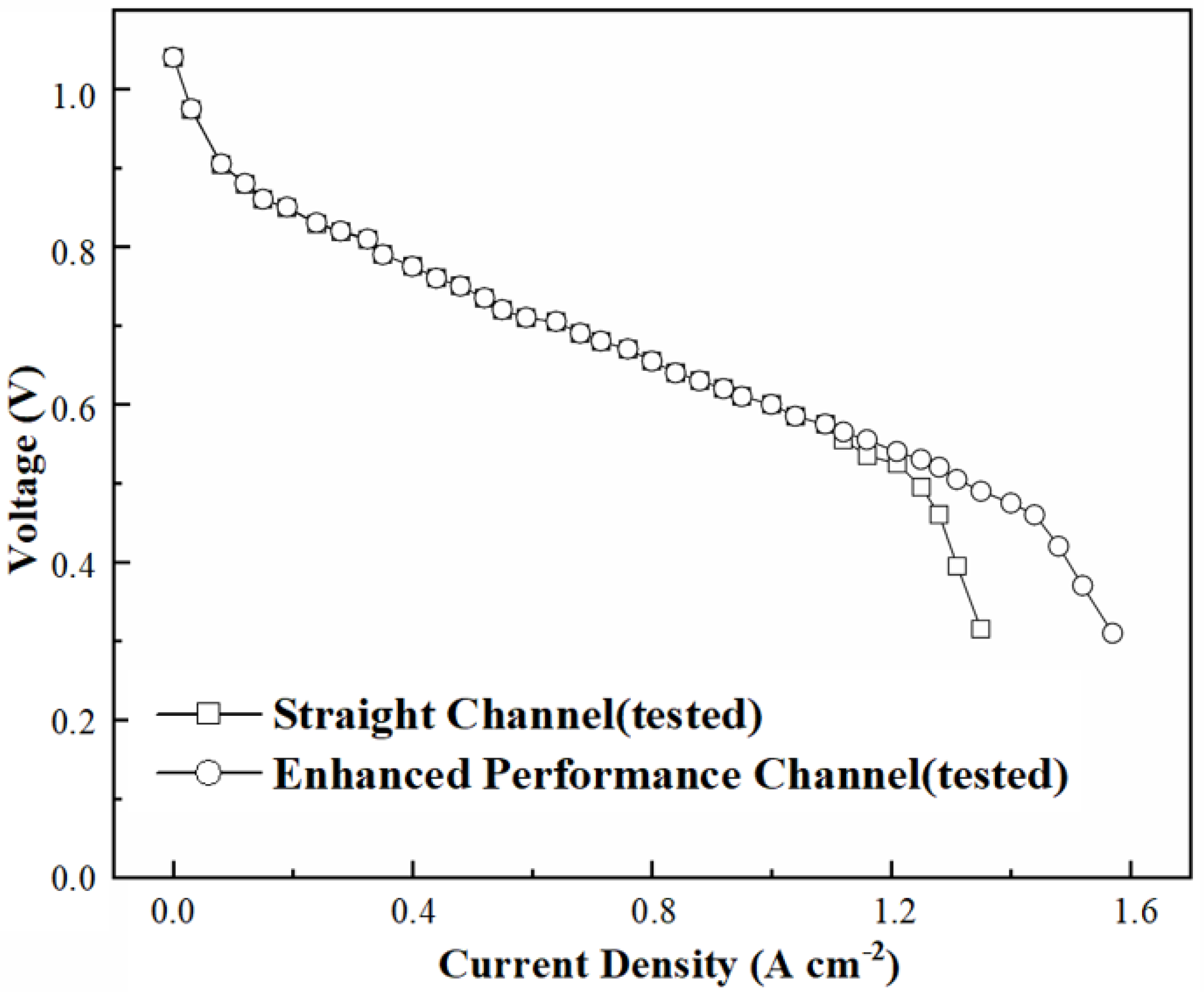
Experiments are also carried out to verify the conclusion that baffles in the cathode channel could enhance the performance of the cell. PEMFC single cells are designed and tested. The dimensionless height of the baffle, total dimensionless length of baffles, and dimensionless length of the single baffle are set to 90%, 21.6%, and 3.6%, respectively.
Figure 7 shows polarization curves of tested cases. It can be seen the maximum net power density of PEMFC without baffles is about 0.624 W·cm−2 when the current density is about 1.2 A∙cm−2. The improvement of the maximum net power density is about 3.85%. The conclusion that baffles in the channel could enhance the performance of cell is verified.
5. Conclusions
In this paper, effects of dimensionless height of the baffle, total dimensionless length of baffles, and dimensionless length of the single baffle on PEMFC performance are investigated. However, the effect of baffle shape and baffle design criterion would be studied in the future. The main conclusions are as follows:
- (1)
- Adding baffles inside cathode channels could help replenish the oxygen in time, enhance the mass transfer inside the channel, GDL and CL, especially in the area under ribs, and improve PEMFC performance. The dimensionless sizes of baffles have a great impact on PEMFC performance.
- (2)
- The mass transfer and PEMFC performance increase with the increase of dimensionless height and total dimensionless length of baffles while decrease with the increase of dimensionless length of the single baffle. However, excessive dimensionless height of the baffle would weaken PEMFC performance due to the extraordinary higher parasitic power.
- (3)
- PEMFC net power density could be increased by 6.29% when the length of the single baffle, the total length of baffles, and height of the baffle are set to 3.6%, 43.2%, and 90%, respectively.
Author Contributions
Conceptualization, Y.C. and J.S.; methodology, J.S.; software, F.W.; validation, J.S., F.W. and Y.C.; formal analysis, Y.C.; investigation, J.S.; resources, B.C.; data curation, Y.C.; writing—original draft preparation, J.S.; writing—review and editing, B.C.; visualization, J.S.; supervision, Y.C.; project administration, B.C.; funding acquisition, B.C. All authors have read and agreed to the published version of the manuscript.
Funding
This research was funded by National Natural Science Foundation of China (No. 52176200).
Institutional Review Board Statement
Not applicable.
Informed Consent Statement
Not applicable.
Data Availability Statement
The data are contained within the article.
Acknowledgments
The authors would like to thank Di Wu for the preparation of experiments.
Conflicts of Interest
The authors declare no conflict of interest.
References
- Kanchan, B.K.; Randive, P.; Pati, S. Numerical investigation of multi-layered porosity in the gas diffusion layer on the performance of a PEM fuel cell. Int. J. Hydrogen Energy 2020, 45, 21836–21847. [Google Scholar] [CrossRef]
- Pourrahmani, H.; Moghimi, M.; Siavashi, M.; Shirbani, M. Sensitivity analysis and performance evaluation of the PEMFC using wave-like porous ribs. Appl. Therm. Eng. 2019, 150, 433–444. [Google Scholar] [CrossRef]
- Yin, Y.; Wu, S.; Qin, Y.; Otoo, O.N.; Zhang, J. Quantitative analysis of trapezoid baffle block sloping angles on oxygen transport and performance of proton exchange membrane fuel cell. Appl. Energy 2020, 271, 115257. [Google Scholar] [CrossRef]
- Zhang, S.-y.; Qu, Z.-g.; Xu, H.-t.; Talkhoncheh, F.-K.; Liu, S.; Gao, Q. A numerical study on the performance of PEMFC with wedge-shaped fins in the cathode channel. Int. J. Hydrogen Energy 2021, 46, 27700–27708. [Google Scholar] [CrossRef]
- Du, F.; Hirschfeld, J.A.; Huang, X.; Jozwiak, K.; Dao, T.A.; Bauer, A.; Schmidt, T.J.; Orfanidi, A. Simulative Investigation on Local Hydrogen Starvation in PEMFCs: Influence of Water Transport and Humidity Conditions. J. Electrochem. Soc. 2021, 168, 074504. [Google Scholar] [CrossRef]
- Mu, Y.-T.; Yang, S.-R.; He, P.; Tao, W.-Q. Mesoscopic modeling impacts of liquid water saturation, and platinum distribution on gas transport resistances in a PEMFC catalyst layer. Electrochim. Acta 2021, 388, 138659. [Google Scholar] [CrossRef]
- Cao, Y.; Ayed, H.; Jafarmadar, S.; Abdollahi, M.A.A.; Farag, A.; Wae-hayee, M.; Hashemian, M. PEM fuel cell cathode-side flow field design optimization based on multi-criteria analysis of liquid-slug dynamics. J. Ind. Eng. Chem. 2021, 98, 397–412. [Google Scholar] [CrossRef]
- Hou, Y.; Deng, H.; Zamel, N.; Du, Q.; Jiao, K. 3D lattice Boltzmann modeling of droplet motion in PEM fuel cell channel with realistic GDL microstructure and fluid properties. Int. J. Hydrogen Energy 2020, 45, 12476–12488. [Google Scholar] [CrossRef]
- Afra, M.; Nazari, M.; Kayhani, M.H.; Sharifpur, M.; Meyer, J.P. 3D experimental visualization of water flooding in proton exchange membrane fuel cells. Energy 2019, 175, 967–977. [Google Scholar] [CrossRef]
- Esbo, M.R.; Ranjbar, A.A.; Rahgoshay, S.M. Analysis of water management in PEM fuel cell stack at dead-end mode using direct visualization. Renew. Energy 2020, 162, 212–221. [Google Scholar] [CrossRef]
- Jeon, D.H. Effect of channel-rib width on water transport behavior in gas diffusion layer of polymer electrolyte membrane fuel cells. J. Power Sources 2019, 423, 280–289. [Google Scholar] [CrossRef]
- Chen, H.; Guo, H.; Ye, F.; Ma, C.F. Modification of the two-fluid model and experimental study of proton exchange membrane fuel cells with baffled flow channels. Energy Convers. Manag. 2019, 195, 972–988. [Google Scholar] [CrossRef]
- He, L.; Hou, M.; Gao, Y.; Sun, X.; Song, W.; Zheng, L.; Ai, J.; Zhang, H.; Shao, Z. Experimental study of the S-shaped flow fields in proton exchange membrane fuel cells. Energy Convers. Manag. 2020, 223, 113292. [Google Scholar] [CrossRef]
- Ijaodola, O.S.; El- Hassan, Z.; Ogungbemi, E.; Khatib, F.N.; Wilberforce, T.; Thompson, J.; Olabi, A.G. Energy efficiency improvements by investigating the water flooding management on proton exchange membrane fuel cell (PEMFC). Energy 2019, 179, 246–267. [Google Scholar] [CrossRef]
- Kumar, R.R.; Suresh, S.; Suthakar, T.; Singh, V.K. Experimental investigation on PEM fuel cell using serpentine with tapered flow channels. Int. J. Hydrogen Energy 2020, 45, 15642–15649. [Google Scholar] [CrossRef]
- Li, W.-Z.; Yang, W.-W.; Wang, N.; Jiao, Y.-H.; Yang, Y.; Qu, Z.-G. Optimization of blocked channel design for a proton exchange membrane fuel cell by coupled genetic algorithm and three-dimensional CFD modeling. Int. J. Hydrogen Energy 2020, 45, 17759–17770. [Google Scholar] [CrossRef]
- Peng, Y.; Mahyari, H.M.; Moshfegh, A.; Javadzadegan, A.; Toghraie, D.; Shams, M.; Rostami, S. A transient heat and mass transfer CFD simulation for proton exchange membrane fuel cells (PEMFC) with a dead-ended anode channel. Int. Commun. Heat Mass Transf. 2020, 115, 104638. [Google Scholar] [CrossRef]
- Choi, S.H.; Kang, D.G.; Lim, I.S.; Lim, H.S.; Park, C.; Kim, M.S. Experimental study on non-uniform arrangement of 3D printed structure for cathodic flow channel in PEMFC. Int. J. Hydrogen Energy 2022, 47, 1192–1201. [Google Scholar] [CrossRef]
- Xia, Z.F.; Chen, H.C.; Zhang, T.; Pei, P.C. Effect of channel-rib width ratio and relative humidity on performance of a single serpentine PEMFC based on electrochemical impedance spectroscopy. Int. J. Hydrogen Energy 2022, 47, 13076–13086. [Google Scholar] [CrossRef]
- Anyanwu, I.S.; Hou, Y.; Xi, F.; Wang, X.; Yin, Y.; Du, Q.; Jiao, K. Comparative analysis of two-phase flow in sinusoidal channel of different geometric configurations with application to PEMFC. Int. J. Hydrogen Energy 2019, 44, 13807–13819. [Google Scholar] [CrossRef]
- Lei, H.; Huang, H.; Li, C.; Pan, M.; Guo, X.; Chen, Y.; Liu, M.; Wang, T. Numerical simulation of water droplet transport characteristics in cathode channel of proton exchange membrane fuel cell with tapered slope structures. Int. J. Hydrogen Energy 2020, 45, 29331–29344. [Google Scholar] [CrossRef]
- Baz, F.B.; Ookawara, S.; Ahmed, M. Enhancing under-rib mass transport in proton exchange membrane fuel cells using new serpentine flow field designs. Int. J. Hydrogen Energy 2019, 44, 30644–30662. [Google Scholar] [CrossRef]
- Badduri, S.R.; Srinivasulu, G.N.; Rao, S.S. Experimental analysis of PEM fuel cell performance using lung channel design bipolar plate. Int. J. Green Energy 2019, 16, 1591–1601. [Google Scholar] [CrossRef]
- Cai, G.; Liang, Y.; Liu, Z.; Liu, W. Design and optimization of bio-inspired wave-like channel for a PEM fuel cell applying genetic algorithm. Energy 2020, 192, 116670. [Google Scholar] [CrossRef]
- Fahruddin, A.; Ichsani, D.; Taufany, F.; Widodo, B.U.K.; Widodo, W.A. The effect of baffle shape on the performance of a polymer electrolyte membrane fuel cell with a biometric flow field. Int. J. Hydrogen Energy 2021, 46, 6028–6036. [Google Scholar] [CrossRef]
- Liu, S.; Chen, T.; Xie, Y.; Zhang, J.; Wu, C. Numerical simulation and experimental study on the effect of symmetric and asymmetric bionic flow channels on PEMFC performance under gravity. Int. J. Hydrogen Energy 2019, 44, 29618–29630. [Google Scholar] [CrossRef]
- Kang, H.C.; Jum, K.M.; Sohn, Y.J. Performance of unit PEM fuel cells with a leaf-vein-simulating flow field-patterned bipolar plate. Int. J. Hydrogen Energy 2019, 44, 24036–24042. [Google Scholar] [CrossRef]
- Chen, X.; Yu, Z.K.; Wang, X.D.; Li, W.B.; Chen, Y.; Jin, C.; Gong, G.C.; Wan, Z.M. Influence of Wave Parallel Flow Field Design on the Performance of PEMFC. J. Energy Eng. 2021, 147, 04020080. [Google Scholar] [CrossRef]
- Chen, X.; Yu, Z.; Yang, C.; Chen, Y.; Jin, C.; Ding, Y.; Li, W.; Wan, Z. Performance investigation on a novel 3D wave flow channel design for PEMFC. Int. J. Hydrogen Energy 2021, 46, 11127–11139. [Google Scholar] [CrossRef]
- Dong, P.; Xie, G.; Ni, M. The mass transfer characteristics and energy improvement with various partially blocked flow channels in a PEM fuel cell. Energy 2020, 206, 117977. [Google Scholar] [CrossRef]
- Ebrahimzadeh, A.A.; Khazaee, I.; Fasihfar, A. Experimental and numerical investigation of obstacle effect on the performance of PEM fuel cell. Int. J. Heat Mass Transf. 2019, 141, 891–904. [Google Scholar] [CrossRef]
- Fan, L.; Niu, Z.; Zhang, G.; Jiao, K. Optimization design of the cathode flow channel for proton exchange membrane fuel cells. Energy Convers. Manag. 2018, 171, 1813–1821. [Google Scholar] [CrossRef]
- Wang, X.; Qin, Y.; Wu, S.; Shangguan, X.; Zhang, J.; Yin, Y. Numerical and experimental investigation of baffle plate arrangement on proton exchange membrane fuel cell performance. J. Power Sources 2020, 457, 228034. [Google Scholar] [CrossRef]
- Wang, B.; Chen, W.; Pan, F.; Wu, S.; Zhang, G.; Park, J.W.; Xie, B.; Yin, Y.; Jiao, K. A dot matrix and sloping baffle cathode flow field of proton exchange membrane fuel cell. J. Power Sources 2019, 434, 226741. [Google Scholar] [CrossRef]
- Yin, Y.; Wang, X.; Shangguan, X.; Zhang, J.; Qin, Y. Numerical investigation on the characteristics of mass transport and performance of PEMFC with baffle plates installed in the flow channel. Int. J. Hydrogen Energy 2018, 43, 8048–8062. [Google Scholar] [CrossRef]
- He, L.; Hou, M.; Gao, Y.; Fang, D.; Wang, P.; Lv, B.; Shao, Z. A novel three-dimensional flow field design and experimental research for proton exchange membrane fuel cells. Energy Convers. Manag. 2020, 205, 112335. [Google Scholar] [CrossRef]
- Guo, Q.Y.; Qin, Y.Z. Numerical investigation of water droplet removal characteristics in novel block channels of PEMFC using dynamic wettability model. Int. J. Hydrogen Energy 2021, 46, 36890–36902. [Google Scholar] [CrossRef]
- Cai, Y.; Wu, D.; Sun, J.; Chen, B. The effect of cathode channel blockages on the enhanced mass transfer and performance of PEMFC. Energy 2021, 222, 119951. [Google Scholar] [CrossRef]
- Shen, J.; Tu, Z.; Chan, S.H. Enhancement of mass transfer in a proton exchange membrane fuel cell with blockage in the flow channel. Appl. Therm. Eng. 2019, 149, 1408–1418. [Google Scholar] [CrossRef]
- Ghasabehi, M.; Ashrafi, M.; Shams, M. Performance analysis of an innovative parallel flow field design of proton exchange membrane fuel cells using multiphysics simulation. Fuel 2021, 285, 119194. [Google Scholar] [CrossRef]
- Garcia-Salaberri, P.A. Modeling Capillary Transport in Thin Porous Media Using a Composite Continuum-Pore Network Formulation: Effect of Water Blockage on Gas Diffusion and Convection. In ECS Meeting Abstracts; IOP Publishing: Chicago, IL, USA, 2021; Volume 27, p. 972. [Google Scholar]
Figure 1.
The schematic illustration.

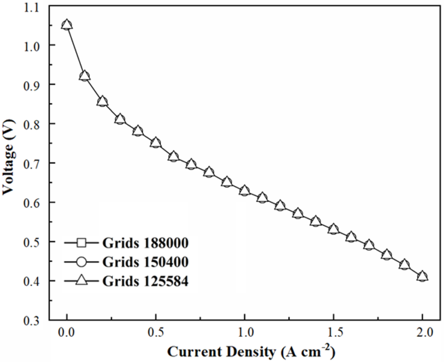
Figure 2.
Polarization curves under different grid numbers.

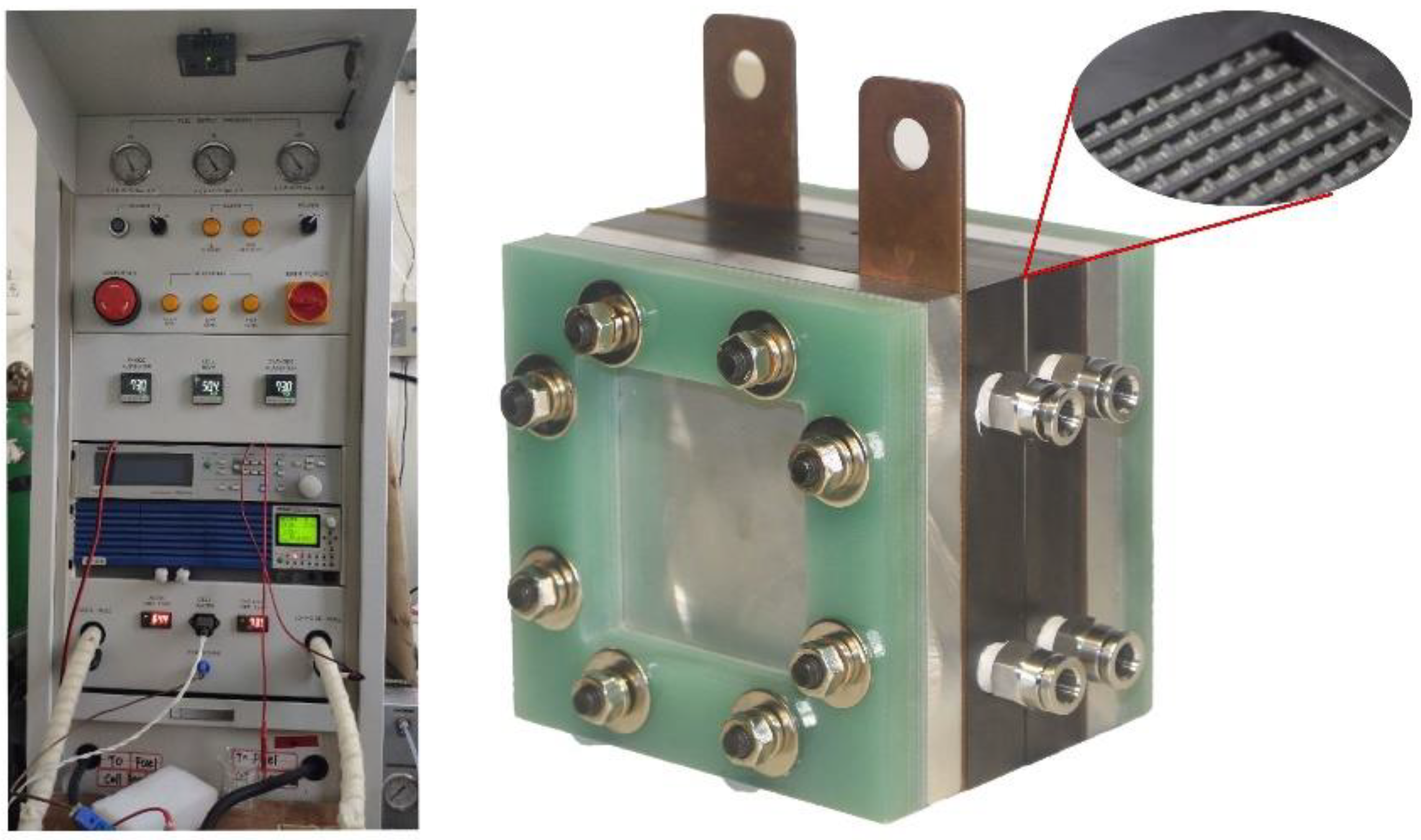
Figure 3.
The test bench and PEMFC single cell.

Figure 4.
Performance of cases under different dimensionless heights of baffles. (a) Polarization curves and gross power curves. (b) Partially enlarged polarization curves. (c) Average oxygen molar concentration between GDL and CL. (d) Contours of oxygen molar concentration at the current density of 1.9 A∙cm−2. (e) Contours of current density distribution at the current density of 1.9 A∙cm−2. (f) Net power density curves.


Figure 5.
Performance of cases under different total dimensionless lengths of baffles. (a) Polarization curves and gross power curves. (b) Partially enlarged polarization curves. (c) Average oxygen molar concentration between GDL and CL. (d) Contours of oxygen molar concentration at the current density of 1.9 A∙cm−2. (e) Contours of the current density distribution at the current density of 1.9 A∙cm−2. (f) Net power density curves.


Figure 6.
Performance of cases under different dimensionless lengths of the single baffle. (a) Polarization curves and gross power curves. (b) Partial enlarged polarization curves. (c) Average oxygen molar concentration between GDL and CL. (d) Contours of oxygen molar concentration at the current density set to 1.9 A∙cm−2. (e) Contours of current density distribution at the current density set to 1.9 A∙cm−2. (f) Net power density curves.


Figure 7.
Experimental validation.


Table 1.
Geometric parameters of the computational model.
| Parameter | Value |
|---|---|
| Current collector length | 50 mm |
| Current collector width | 2 mm |
| Rib area width | 1 mm |
| Flow channel width | 1 mm |
| Flow channel height | 0.85 mm |
| Flow channel length | 50 mm |
| Gas diffusion layer (GDL) height | 0.15 mm |
| Catalyst layer (CL) height | 0.01 mm |
| Membrane height | 0.025 mm |
Table 2.
Operating conditions.
| Parameter | Valve |
|---|---|
| Operation temperature | 353.15 K |
| Reference current density | 1 Acm−2 |
| Anode/cathode pressure | 101,325 Pa |
| Faraday constant | 96,487 Cmol−1 |
| Gas constant | 8314 Jkmol−1 K−1 |
| Electron number for anode reaction | 2 |
| Electron number for cathode reaction | 4 |
| Mass flow rate (cathode) | 1 × 10⁻⁶ kg s−1 |
| Mass flow rate (anode) | 1 × 10⁻⁷ kg s−1 |
| Relative humidity (cathode) | 90% |
| Relative humidity (anode) | 50% |
| Porosity (gas diffusion layer) | 0.6 |
| Porosity (catalyst layer) | 0.2 |
Table 3.
Detailed parameters of PEMFC single cell.
| Component | Length × Width × Height (mm) | Material |
|---|---|---|
| Flow field | 100 × 100 × 18 | Graphite |
| Current collector | 100 × 100 × 2 | Brass H80 |
| End plate | 100 × 100 × 12 | Aluminum alloy 6061 |
| Insulating plate | 100 × 100 × 10 | Epoxy resin |
| Sealant | 100 × 100 × 0.15 | PTFE |
| Gas diffusion layer | 54 × 54 × 0.19 | Toray TGP-H-060 |
| Membrane | 50 × 50 × 0.025 | Nafion®112 |
Table 4.
Cases under different dimensionless heights of baffles.
| Case | 1 | 2 | 3 | 4 | 5 |
|---|---|---|---|---|---|
| The ratio of the baffle height to the channel height | 0 | 50% | 70% | 90% | 94% |
| The ratio of the baffle total length to the channel length | 0 | 21.6% | 21.6% | 21.6% | 21.6% |
| The ratio of the single baffle length to the channel length | 0 | 3.6% | 3.6% | 3.6% | 3.6% |
Table 5.
Cases performance under different dimensionless heights of baffles.
| Case | 1 | 2 | 3 | 4 | 5 |
|---|---|---|---|---|---|
| The ratio of the baffle height to the channel height | 0 | 50% | 70% | 90% | 94% |
| Gross power density (W/cm2) | 0.7916 | 0.8128 | 0.8219 | 0.8375 | 0.8537 |
| Percentage increase in gross power density | 2.67% | 3.83% | 5.79% | 7.96% | |
| Pumping power density (W/cm2) | 0.0002 | 0.0003 | 0.0004 | 0.0041 | 0.0228 |
| Net power density (W/cm2) | 0.7914 | 0.8124 | 0.8215 | 0.8331 | 0.8319 |
| Percentage increase in net power density | 2.66% | 3.81% | 5.27% | 5.12% |
Table 6.
Cases under different total dimensionless lengths of baffles.
| Case | 1 | 6 | 7 | 8 | 9 | 10 |
|---|---|---|---|---|---|---|
| The ratio of the baffle height to the channel height | 0 | 90% | 90% | 90% | 90% | 90% |
| The ratio of the baffle total length to the channel length | 0 | 10.8% | 21.6% | 32.4% | 37.8% | 43.2% |
| The ratio of the single baffle length to the channel length | 0 | 5.4% | 5.4% | 5.4% | 5.4% | 5.4% |
Table 7.
Cases performance under different total dimensionless lengths of baffles.
| Case | 1 | 6 | 7 | 8 | 9 | 10 |
|---|---|---|---|---|---|---|
| The ratio of the baffle total length to the channel length | 0 | 10.8% | 21.6% | 32.4% | 37.8% | 43.2% |
| Gross power density (W/cm2) | 0.7916 | 0.8155 | 0.8375 | 0.8396 | 0.8419 | 0.8445 |
| Percentage increase in gross power density | 3.01% | 5.79% | 6.06% | 6.36% | 6.68% | |
| Pumping power density (W/cm2) | 0.0002 | 0.0021 | 0.0041 | 0.0048 | 0.0052 | 0.0055 |
| Net power density (W/cm2) | 0.7914 | 0.8134 | 0.8331 | 0.8348 | 0.8367 | 0.8390 |
| Percentage increase in net power density | 2.79% | 5.27% | 5.48% | 5.73% | 6.01% |
Table 8.
Cases under different dimensionless lengths of the single baffle.
| Case | 1 | 11 | 10 | 12 |
|---|---|---|---|---|
| The ratio of the baffle height to the channel height | 0 | 90% | 90% | 90% |
| The ratio of the baffle total length to the channel length | 0 | 43.2% | 43.2% | 43.2% |
| The ratio of the single baffle length to the channel length | 0 | 3.6% | 5.4% | 7.2% |
Table 9.
Cases performance under different dimensionless lengths of the single baffle.
| Case | 1 | 11 | 10 | 12 |
|---|---|---|---|---|
| The ratio of the single baffle length to the channel length | 0 | 3.6% | 5.4% | 7.2% |
| Gross power density (W/cm2) | 0.7916 | 0.8471 | 0.8445 | 0.8421 |
| Percentage increase in gross power density | 7.01% | 6.68% | 6.38% | |
| Pumping power density (W/cm2) | 0.0002 | 0.0060 | 0.0055 | 0.0052 |
| Net power density (W/cm2) | 0.7914 | 0.8411 | 0.8390 | 0.8368 |
| Percentage increase in net power density | 6.29% | 6.01% | 5.74% |
Publisher’s Note: MDPI stays neutral with regard to jurisdictional claims in published maps and institutional affiliations. |
© 2022 by the authors. Licensee MDPI, Basel, Switzerland. This article is an open access article distributed under the terms and conditions of the Creative Commons Attribution (CC BY) license (https://creativecommons.org/licenses/by/4.0/).
Share and Cite
MDPI and ACS Style
Cai, Y.; Sun, J.; Wei, F.; Chen, B. Effect of Baffle Dimensionless Size Factor on the Performance of Proton Exchange Membrane Fuel Cell. Energies 2022, 15, 3812. https://0-doi-org.brum.beds.ac.uk/10.3390/en15103812
AMA Style
Cai Y, Sun J, Wei F, Chen B. Effect of Baffle Dimensionless Size Factor on the Performance of Proton Exchange Membrane Fuel Cell. Energies. 2022; 15(10):3812. https://0-doi-org.brum.beds.ac.uk/10.3390/en15103812
Chicago/Turabian StyleCai, Yonghua, Jingming Sun, Fan Wei, and Ben Chen. 2022. "Effect of Baffle Dimensionless Size Factor on the Performance of Proton Exchange Membrane Fuel Cell" Energies 15, no. 10: 3812. https://0-doi-org.brum.beds.ac.uk/10.3390/en15103812
Note that from the first issue of 2016, this journal uses article numbers instead of page numbers. See further details here.