
A Novel Optimal Power Allocation Control System with High Convergence Rate for DC Microgrids Cluster


1
Department of Electrical Engineering, Faculty of Engineering, Aswan University, Aswan 81542, Egypt
2
Department of Electrical Engineering, Harbin Institute of Technology, Harbin 150001, China
*
Authors to whom correspondence should be addressed.
Energies 2022, 15(11), 3994; https://0-doi-org.brum.beds.ac.uk/10.3390/en15113994
Submission received: 14 April 2022
/
Revised: 25 May 2022
/
Accepted: 25 May 2022
/
Published: 28 May 2022
(This article belongs to the Special Issue Optimal Dispatch of Microgrid and Microgrid Cluster)
Abstract
:A novel, fully distributed controller with a rapid convergence rate is developed to ensure the optimal loading dispatch for interconnected DC MGs. It comprises local and global-control levels, handling the economic load allocations in a finite-time manner, for distinct MGs and cluster of MGs, respectively. The local-control layer guarantees MG’s economic operation by matching the incremental costs (ICs) of all DGs, respecting the power equilibrium among generations and demands, DGs’ generation limits, as well as the transmission line losses. Furthermore, the economic operation of battery energy sources is considered, in the optimization problem, to strengthen the overall reliability and maximize energy arbitrage. The global controller adjusts MGs’ voltage references to determine the optimal exchanged power, between MGs, for reducing the global total generation cost (TGC). A rigorous analysis is developed to confirm the stable convergence of the developed controller. Extensive simulation case studies demonstrate the superiority of the proposed control system.
1. Introduction
With the unprecedented increased penetration of DC renewable energy sources (RES) (e.g., photovoltaics and fuel cells), DC energy storage systems (e.g., batteries and electric vehicles), and DC loads in the modern distribution networks, DC microgrids (MGs) have appeared as a promising way to ensure efficient and resilient electric networks [1,2]. Besides, they are immune to the inherent problems of AC MGs, such as reactive power control, DC/AC power conversion losses, synchronization, and inrush current [3,4]. Despite the advantages of DC MGs, a single MG may be subject to generation-demand power imbalance due to the volatility of RES and load uncertainty, which deteriorates the system reliability and stability [5]. To overcome this problem, coupling DC MGs in close vicinity, to form a DC MGs cluster, improves the overall reliability and availability, owing to the transferred power between MGs [6,7]. As a result, RES’ utilization is impressively maximized, the stress and aging of the MG’s components are alleviated, and the system’s efficiency is increased [8].
In general, the control framework for the multi-MGs consists of three layers: namely primary, secondary, and tertiary controllers [9,10]. The primary controller of each DG adopts the droop control and the inner control loops, for sustaining adequate power-sharing, with only local measurements [11]. Besides, the secondary controller is in charge of compensating voltage deviations caused by droop controller and preserving proper load sharing between local DGs [12]. Finally, the tertiary controller ensures the global economic operation of the multi-MGs by assigning MG’s voltage to carry out the scheduled power exchange among MGs [13]. The control framework can be classified into centralized, decentralized, and distributed control strategies [14]. In centralized control schemes, the controller gathers all the required data from the controlled units for solving the problem and sends the proper commands back to them. Consequently, it requires a complicated high bandwidth cyber network, and it may suffer from a single-point-of-failure that reduces systems reliability and expandability. Furthermore, the decentralized control schemes attain the control objectives without cyber networks to enhance the overall system’s reliability [15]. Although it is distinguished with its simple and reliable structure, there are some limitations to its performance because of the shortage of a global system’s data. Distributed control schemes have emerged as the most attractive, reliable, and flexible solution that overcomes the shortcomings of both decentralized and centralized control schemes [16]. Consequently, it garnered massive research attention due to the elimination of the single-point-of-failure, and the higher scalability and reliability with fewer computational and cyber requirements [17].
A distributed control policy for DC multi-MGs has been presented in [18] for maintaining the appropriate exchanged power among MGs based on batteries’ state-of-charge (SoC); however, a central controller is still required to manage the power flow among MGs. A fully distributed, two-layer tertiary control strategy is presented in [19] for maintaining an equal power sharing among MGs and a regulated average voltage in a cluster of DC MGs. Furthermore, a leader-based fully distributed secondary controller is developed in [20] for DC multi-MGs, which achieves MG’s voltage restoration and per unit current sharing according to the setpoints of the higher control level. A fully distributed master-slave controller is illustrated in [21] for regulating DGs’ voltages and instantaneously attain proportional power allocation within each MG and among interconnected DC MGs. In [22], a distributed multilayered control framework for the power management of battery energy storage systems (BES) in DC MG clusters is utilized. Voltage regulation and equal current sharing for BES within each MG and the entire cluster can be achieved. A cyber-resilient fully distributed cooperative control system for networked DC MGs with regulated voltage and equalized current sharing is presented in [23]. Since MGs consist of different kinds of DGs having dissimilar operating costs, economic load sharing gains a paramount interest in optimizing the cluster’s TGC.
A distributed hierarchical controller has been proposed in [24] for optimizing the loading dispatch in interconnected DC MGs, based on the well-known equal incremental cost (IC) scheme. In [25], the global TGC for a cluster of DC MGs is optimized by respecting generations-demands equilibrium, and DGs’ output power constraints in a fully distributed manner. In [26], a fully distributed tie-line power flow control scheme is unified with the distributed optimal power allocation control in multiple DC MGs. A master-salve cluster cooperation control strategy is developed in [27] to enable economic current sharing among DC multi-MGs. However, it is assumed that all DGs within each MG have the same operating cost, which is not practical. In [28], a hierarchically coordinated controller for DC MG clusters is presented to optimize the energy sharing among MGs under uncertainties.
The results presented in the abovementioned works employ the linear consensus protocol with infinite convergent time, which might be improper for treating MGs’ intermittent operational circumstances, due to RES and frequent loadings dynamics. The work in [29] elaborates on the algebraic connectivity of the cyber network, the second smallest eigenvalues of the graph’s Laplacian matrix, which has a direct effect on the convergence time. Accordingly, in [30], a distributed control system is proposed to minimize the TGC for a cluster of DC MGs. Wherein the estimated connected cyber topology is proposed to attain an accelerated convergence rate. Although the TGC for a cluster of DC MGs is minimized, a centralized cyber network is employed to send the desired global IC reference to the local controllers.
The work in [31] proposes the finite-time consensus protocol to pursue stable and reliable operation, with a rapid convergent rate compared to the conventional linear consensus scheme. In this context, a fully distributed controller is presented in [32] for optimizing the power-sharing between MGs, with a high convergence rate respecting the generations-demands power balance and DGs’ generation boundaries. Furthermore, utilizing the finite-time control theory, a fully distributed two-layer control scheme is presented in [33] to minimize the TGC for interconnected DC multiple MGs, wherein the transmission line (T.L) losses have been taken into consideration in the optimization problem. Since the BES becomes a dominant part of the smart grid, its charging/discharging power should be managed in order to increase the overall energy arbitrage of the multi-MGs [34]. From the economic point of view, it is recommended to charge the BES if the electricity price is low and oppositely discharge if the electricity price is high. According to the authors’ best knowledge, solving the economic dispatch problem (EDP) for a cluster of DC MGs with an accelerated convergence manner, while considering the optimal charging/discharging of BES, has not been previously considered, as summarized in Table 1.
This article introduces a fully distributed finite-time control system composed of local and global-control levels to guarantee the economic power sharing between heterogeneous DGs for DC multi-MGs. The global-control layer, based on the finite-time consensus protocol, regulates the power sharing between the interconnected MGs by adjusting the MGs’ voltage references for minimization of the global TGC. Furthermore, the local-control layer maintains equal ICs, for all DGs within the MG, to ensure economic load sharing. Moreover, the local-control layer regulates MG’s average voltage at the value given by the global-layer to guarantee the generation-demand power balance. The key significances of the developed control strategy compared to the existing control strategies are summarized in Table 1 and can be listed as:
- ⮚
- ⮚
- Contrary to the existing works, the BES’s generation cost is considered in the optimization problem respecting SoC boundaries. BES charges during the electricity price if it is low and discharges if it is high.
- ⮚
- The global generations-demands power equilibrium in the multi-MGs is properly accomplished by fulfilling the boundaries of DGs output powers and T.L losses.
- ⮚
- A simple and sparse two-layer cyber network has been modeled to convey the information locally among local DGs, within each MG, and globally among the interconnected MGs.
- ⮚
- The proposed controller has the resiliency under both cyber losses and delays, as well as MG’s plug-and-play.
The rest of the paper is structured as follows: Section 2 presents the multi-MGs’ structure, the basics of the EDP, and the finite-time controller. The developed hierarchical finite-time control system is discussed in Section 3. Section 4 states the efficacy of the developed control system by examining it, on multiple interconnected MGs, through simulations. Lastly, Section 5 introduces the summary and conclusion of the paper.
2. System Description and Preliminaries
2.1. Modeling of DC Multi-MGs and the EDP
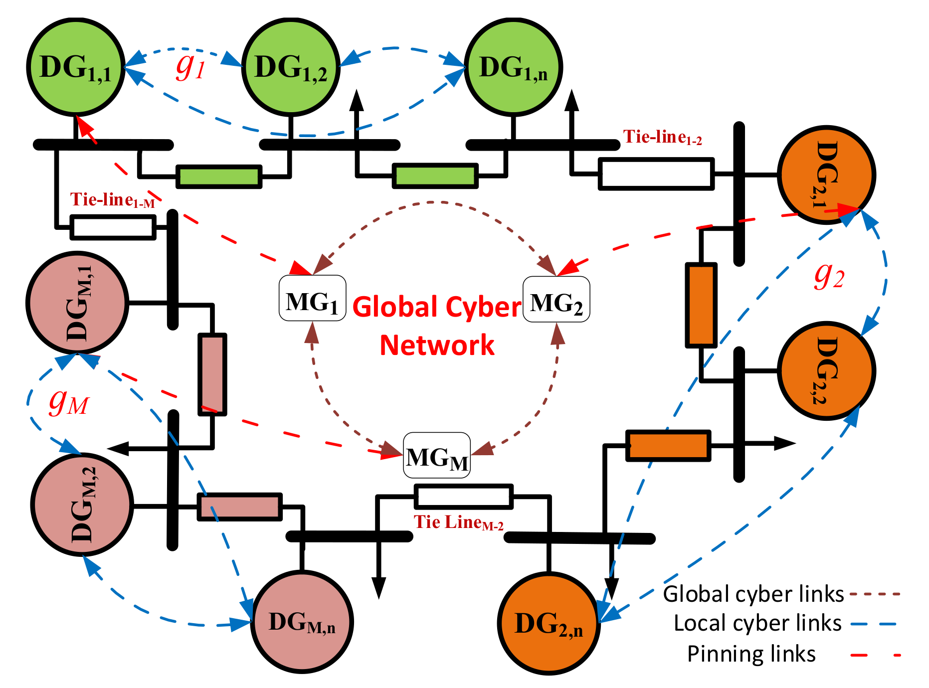
The single-line diagram of the modeled DC multi-MGs is illustrated in Figure 1. It involves interconnected DC MGs, which are labeled as ,… ,…, and . The DC MGs are connected directly through tie-lines; therefore, the exchanged power among DC MGs depends on the voltage difference between their buses’ voltages. Each MG has DGs of various natures, including dispatchable and non-dispatchable DGs connected with T.L to supply the local demands. RES, such as wind turbines and photovoltaics, are non-dispatchable DGs due to their intermittent operations. Since RES’ operating cost is negligible, they are excluded from the EDP and controlled to produce their maximum available powers, while the conventional generators, such as fuel-based generators, are known as dispatchable DGs, and their operating cost is usually expressed in a quadratic form in terms of their generated powers .
where the nonnegative constants, , and are generation cost constants of the ith generator within MGM.
Battery energy storage (BES) systems are considered dispatchable generators, as they have the absorption capability of the extra energy in the MG during the charging mode or cover the deficiency of the generation in the MG during the discharging mode. To guarantee the optimal operation of the BES units, they should be controlled to discharge during periods of high electricity rates; otherwise, it operates in the discharging mode [34]. Additionally, the depth of discharge, the charge rate, and the degradation cost have a direct effect on the BES’ generation cost [35,36]. Therefore, inspired by [34], a general formulation of the generation cost function for the BES is addressed as
where , and represent the factors of ’s production cost, is its charge/discharge power, and denotes the current state of charge (SoC). and symbolize the minimum and maximum SoC limits, respectively. denotes the upper limit of the rate of charge/discharge, and the IC is defined as the derivative of the cost function with respect to its generated/absorbed power , as in (3) [34].
Consequently, the EDP of the multi-MGs considering BES production cost can be formulated as follow:
For convenience, symbolizes the output power for both DGs and BES, while and denote the lower and upper limits of the dispatchable DGs, respectively. Therefore, (4a) can be rewritten as
Firstly, the inequality constraint (5c) and the transmission line losses are neglected. For maintaining the optimal power dispatch of the multi-MGs, the Lagrange operator can be expressed as
where indicates the Lagrange multiplier related to the equality constraint (4b). The Lagrange operator is optimized by solving these equations
Therefore, it is essential to maintain the equalization of all DGs’ ICs in the multi-MGs to ensure the optimal loading dispatch under the condition of neglecting the DGs’ production limits.
Secondly, considering the transmission losses in the EDP is essential to have a practical model. Based on the micro-incremental line losses for DGs [37], line power losses associated with can be expressed as follows:
where is the power losses factor meeting . Subsequently, the optimum IC of the cluster can be modified as follow:
Finally, considering the inequality constraint, the optimal operating conditions can be expanded slightly, as in [38]:
2.2. Two-Layers Cyber Networks
Figure 1 depicts the modeled two-layer cyber network, consisting of local and global levels, for sharing data between DGs, within the MG and globally, among interconnected DC MGs. Each MG has its own local graph ; accordingly, the local cyber layer incorporates N graphs related to the DC MGs within the multi-MGs. The local DGs within each MG represent the nodes of the communication graph , and the cyber link among two DGs signifies the edge between two nodes . If all the edges are bidirectional, the communication graph is termed an undirected graph; otherwise, it is called a directed graph. The communication weights of the local edges, , are listed on a matrix named the adjacency matrix . The value of is positive only if receives data from its neighbor ; otherwise, [29]. Let signifies the graph Laplacian matrix with for and . [39].
At least one DG is pinned within each MG for formulating the global sparse cyber layer and facilitating data conveyance between MGs. Accordingly, the global cyber graph consists of a set of nodes signifying MGs in the cluster . The set of edges represents the cyber links among MGs having communication weights, which are symbolized with and arranged in the adjacency matrix . Additionally, the pinning cyber links are presented for transferring data among the local and global layers. Therefore, the pinning gain, implies the communication weight of the pinning link from the agent to the pinned generators , where a positive gain is used for each pinning link, otherwise for the unpinned DGs. The diagonal pinning matrix of is denoted by carrying all the pinning gains.
2.3. Hypothesis of the Finite-Time Controller
In this subsection, the basic principles of the finite-time control theory are stated. At first, considering the nonlinear autonomous system defined by:
where is continuous on, and . The work in [31] stated that, for the system (11), the origin is globally finite-time stable only if the origin is Lyapunov stable and finite-time convergent
Lemma 1
([40]). Letting as a continuous positive definite function of system (11) as follow
where and non-negative factors fulfilling . Consequentlyconverges to the zero steady state within a finite-settling time
Lemma 2
Lemma 3
Lemma 4
([42]). For an undirected graph, Laplacian matrix’s features are as follow:
wherein, symbolizes the second smallest eigenvalue of the Laplacian matrix , then .
Lemma 5
Let denotes the second smallest eigenvalue of , then .
3. The Proposed Control Strategy
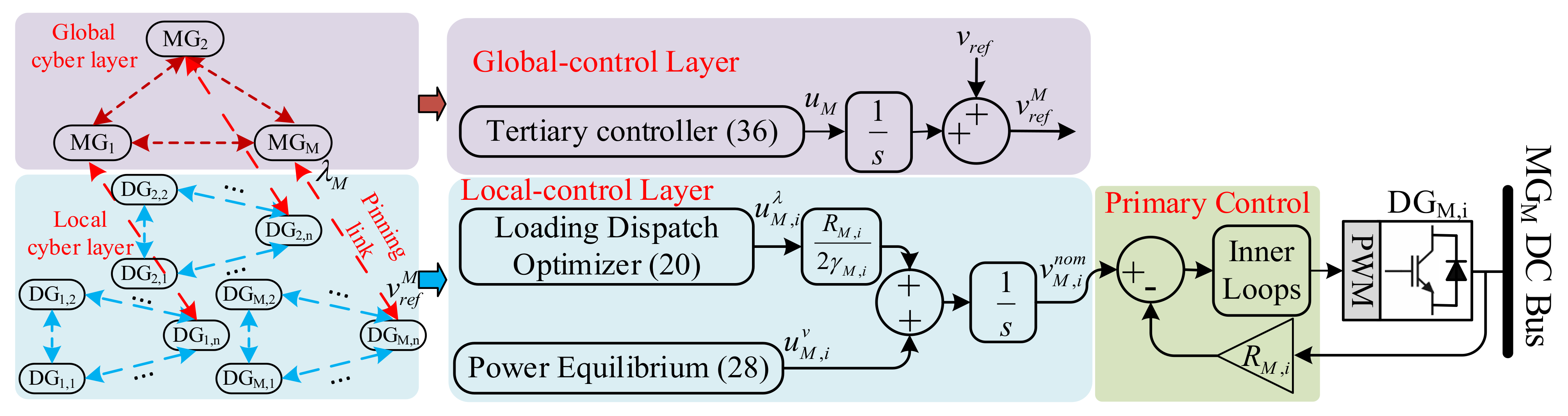
The high intermittency of RES maximizes the necessity to accelerate the convergence speed of the designed distributed controller and guarantee reliable operation of the multi-MGs. The developed fully distributed finite-time controller is proposed to resolve the EDP for DC multi-MGs within a predetermined finite-settling time. This can be attained by realizing an agreement on DGs’ ICs in the DC multi-MGs, respecting the restrictions of the EDP. Figure 2 illustrates that the proposed controller involves two control levels: (1) global-control level (tertiary control) decreases the overall TGC, in a finite-time approach, by adjusting MGs’ voltage references , at which their ICs are equalized to maintain the economic power flow among them; (2) local-control level (secondary control) restores the average voltage across the MG at the voltage reference assigned by the global-control level, as well as matches the ICs of all DGs while adjusting the nominal voltage of the primary control layer as
where is the measured output voltage of , and represents its droop gain. Furthermore, the drooping formulation of the primary controller is rewritten as a function of ’s IC as follows:
3.1. Local-Control Layer
The Local-control layer is designed to guarantee matching DGs’ ICs in the MG and restore the average voltage across the MG at the nominal value in a finite-time manner. Therefore, differentiating (15) yields
where and signifies both the voltage and cost control inputs, respectively. As a result, the nominal voltage of the primary controller can be determined by
Defining the auxiliary control inputs and as the key objective of the MG-control layer, in order to properly state the nominal voltage of the primary control layer and achieve the main control objectives, is such that:
Balancing the ICs of all DGs in the MG, which can be realized within a finite-time limited with, to reduce the TGC.
Restoration of the average voltage across the MG at the given references within a finite time limited by.
3.1.1. Distributed Local Finite-Time Loading Dispatch Optimizer
Equalizing the ICs of all the dispatchable DGs within the MG would lead to the optimal loading dispatch between them. Consequently, based on the peer-to-peer cyber procedure [31], a fully distributed finite-time cost control input is developed, as in (20), in which the controller of each DGM,i compares its local IC with the ones of the neighboring DGs at the MG; consequently, after a finite-settling time , the ICs of all DGs will be converged to the optimal value, and the generation cost is minimized.
where and are the positive control factors, and. , signifies the signum function, as well as indicates the set of ’s neighbors in the lower cyber network.
Theorem 1.
Let the undirected lower cyber graphis connected, with utilizing the distributed finite-time controller (20), all DGs’ ICs agreement can be achieved in an upper bounded finite-time,.
Proof.
Signify the local IC mismatch. Since for an undirected graph, is time invariant. Next, the first derivative of the IC mismatch can be formulated as follows
Consider the Lyapunov function
where signifies the disagreement vector. Accordingly, differentiating (21) yields
State the adjacency matrix of the undirected graph as , and represents Laplacian matrix.
According to Lemma 2,
According to Lemmas 3 and 4, one gets
Let , then we have
Based on Lemma 1, ICs mismatch equals 0 in a finite settling time limited by
Finally, all DGs within the MG have matched ICs, i.e., , in a finite time , and the proof of Theorem 1 is completed. □
3.1.2. Distributed Local Finite-Time Power Equilibrium
Typically, in DC MGs, fulfilling the equilibrium between generations and demands can be attained with a regulated MG’s average voltage. Therefore, by employing the dynamic consensus protocol [19], the distributed voltage observer has been developed for estimating MG’s average voltage, as in (27). Each DG can determine the average voltage across the MG only with its measured bus voltage, and the estimations of the neighboring DGs in the lower cyber layer are as follows
where denotes the estimation of ’s average voltage at . Next, to ensure a regulated average voltage across the MG, a distributed voltage regulator is developed based on the pinning-based finite-time control theory, as in (28). At least one DG is pinned to receive the voltage reference appointed by the global control level. Subsequently, the pinned DGs compare their local average voltage estimations with the ones of their neighbors and with the assigned MG’s nominal voltage for formulating the auxiliary voltage control input as follows
where indicates the pinning gain associated with the pinned DGs, and is positive only if accesses ’s voltage reference from the global controller; otherwise, . Therefore, the unpinned DGs compare their estimations of MG’s average voltage only with those of their neighbors.
Theorem 2.
Let the connected and undirected local cyber graph, employing the proposed finite-time controller (28) maintains the generations-demands equilibrium as well as MG’s average voltage is effectively regulated at the nominal value given by the global-controller within a finite settling time.
Proof.
State the average voltage mismatch error . As with the proof of Theorem 1, the derivative of leads to
Consider the Lyapunov function
where is the disagreement vector. Differentiating the Lyapunov function is
Set the adjacency matrix of the undirected graph as , and symbolizes the Laplacian matrix. indicates the pinning matrix.
According to Lemma 2, one gets
According to Lemmas 3 and 5, one gets
Let , then we have
Accordingly, based on Lemma 1, MG’s average voltage is effectively restored at the required voltage reference in a finite time restricted by as in (35), and this completes the proof of Theorem 2.
Remark 1. Based on Theorem 1 and Theorem 2, all DGs’ ICs matching, and regulating the average voltage across MGs can be preserved within an upper bounded settling time as.
3.2. Global-Control Layer
The developed global-controller adjusts the transferred powers between interconnected DC MGs to reduce the global TGC of the multi-MGs within a finite-settling time. This can be realized by adjusting the nominal voltage of each MG, as they are connected through T.L, and the exchanged power can be determined based on the buses’ voltages difference. Accordingly, each MG is modeled as a node on the global sparse cyber network to convey the needed data to other MGs in a distributed manner. Furthermore, as the local-control layer effectively matches the ICs of all DGs within the MG, the IC of the pinned DG represents the value of MG’s IC (). Utilizing the distributed finite-time control philosophy, the global controller of each MG compares its ICs, with the ICs of the neighboring MGs () in the global cyber network, as in (36). Therefore, the ICs of all MGs converge at the optimal value in a finite-time upper-bounded by. Finally, the nominal voltage of the MG () can be calculated, as in (18), and sent to the pinned DG through the pinned cyber link for updating the average voltage across the MG, thanks to the local controller, as in (20).
Theorem 3.
Assume an undirected global cyber graphis connected. Using the proposed distributed finite-time control system (36), the convergence of MGs’ ICs can be achieved in a finite settling time limited by
Proof.
Denote the global IC mismatch . Since for an undirected cyber graph, is time invariant. Accordingly, differentiating results
Let the following Lyapunov function candidate
where is the disagreement vector. Thus, differentiating (40) yields
The rest of the proof have the same steps listed in proof of Theorem 1; hence, it is not repeated here for brevity. □
4. Controller Verification
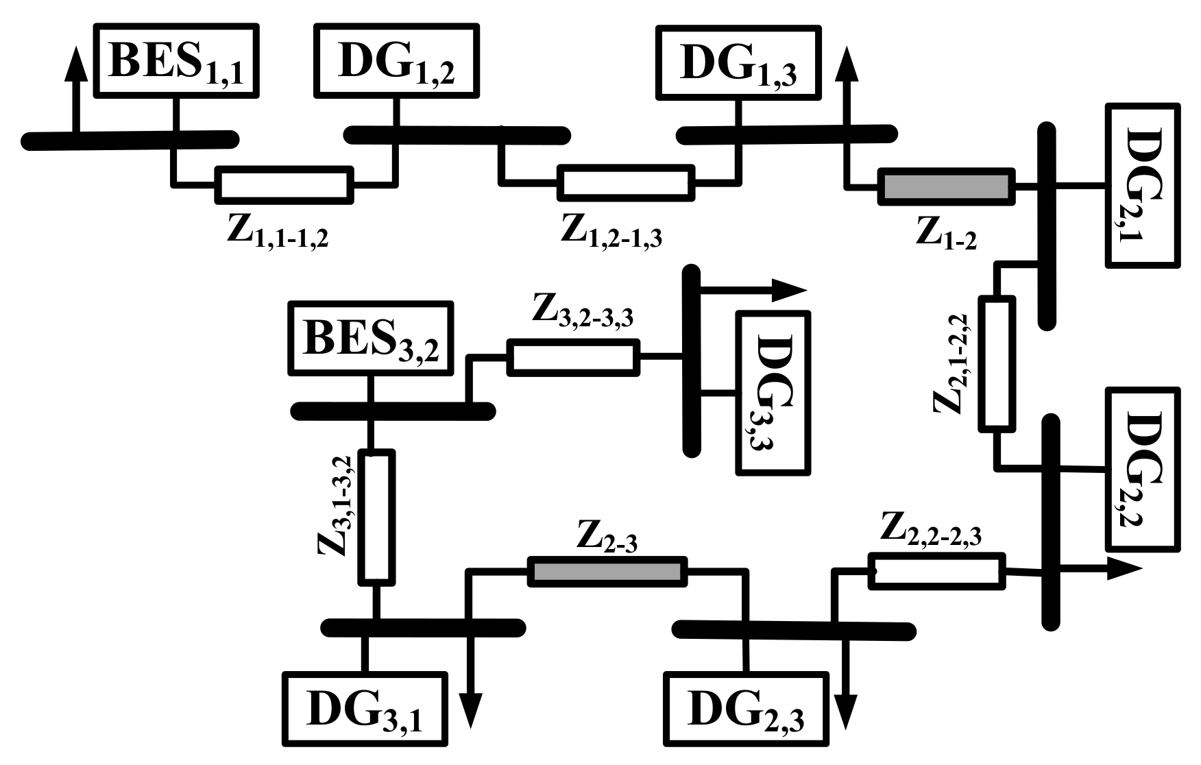
To verify the effectiveness of the proposed finite-time controller, a 200 V DC multi-MGs is modeled using PLECS, as seen in Figure 3. Each MG encompasses three DGs, which are emulated by DC-DC boost converters and connected by local T.L. Table 2 presents the parameters of DGs’ production costs, local and global T.L, as well as the dual-layer controller. The initial values of the SoC for and are set to be 50%. The adjacency matrices of the dual-layer cyber network are and , thus having a balanced Laplacian matrix. Furthermore, , , and are set to be the pinned DGs for the MGs; therefore, MGs’ diagonal pinning matrices are .
4.1. Controller Performance
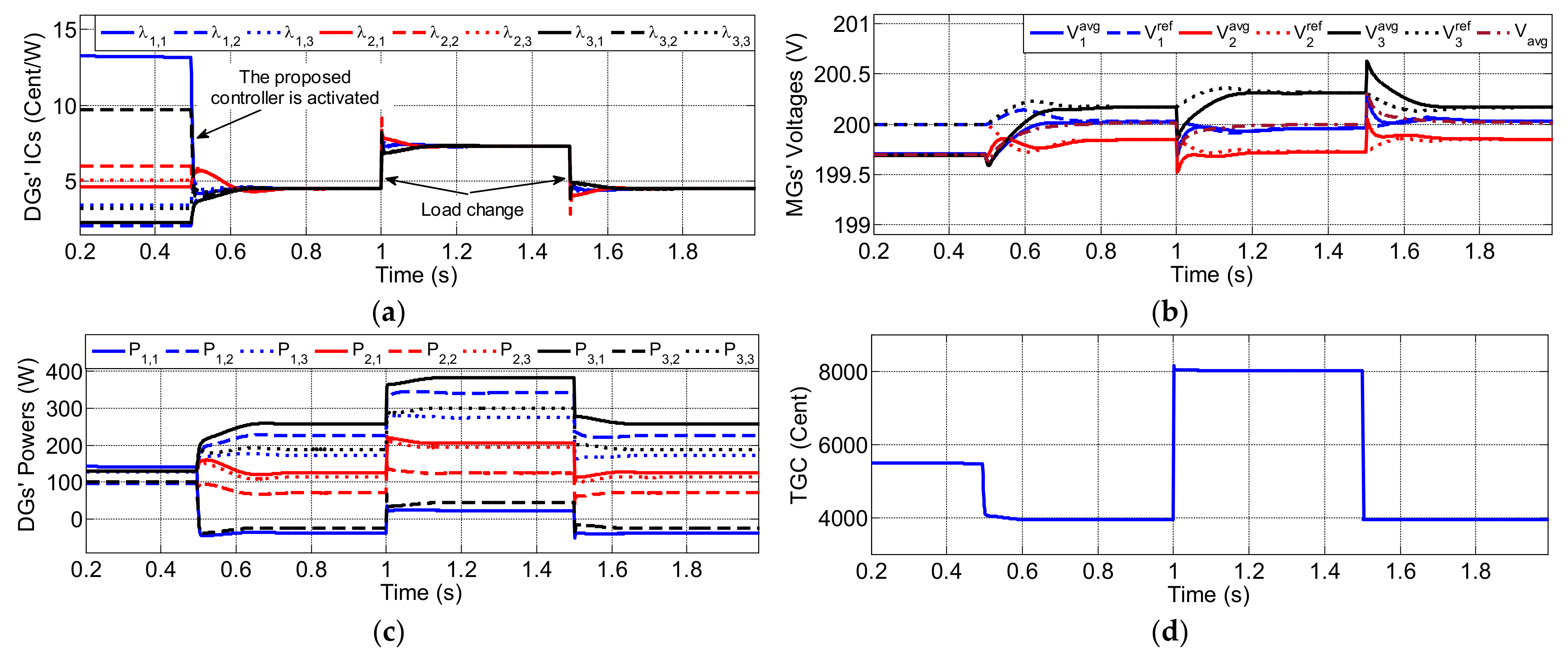
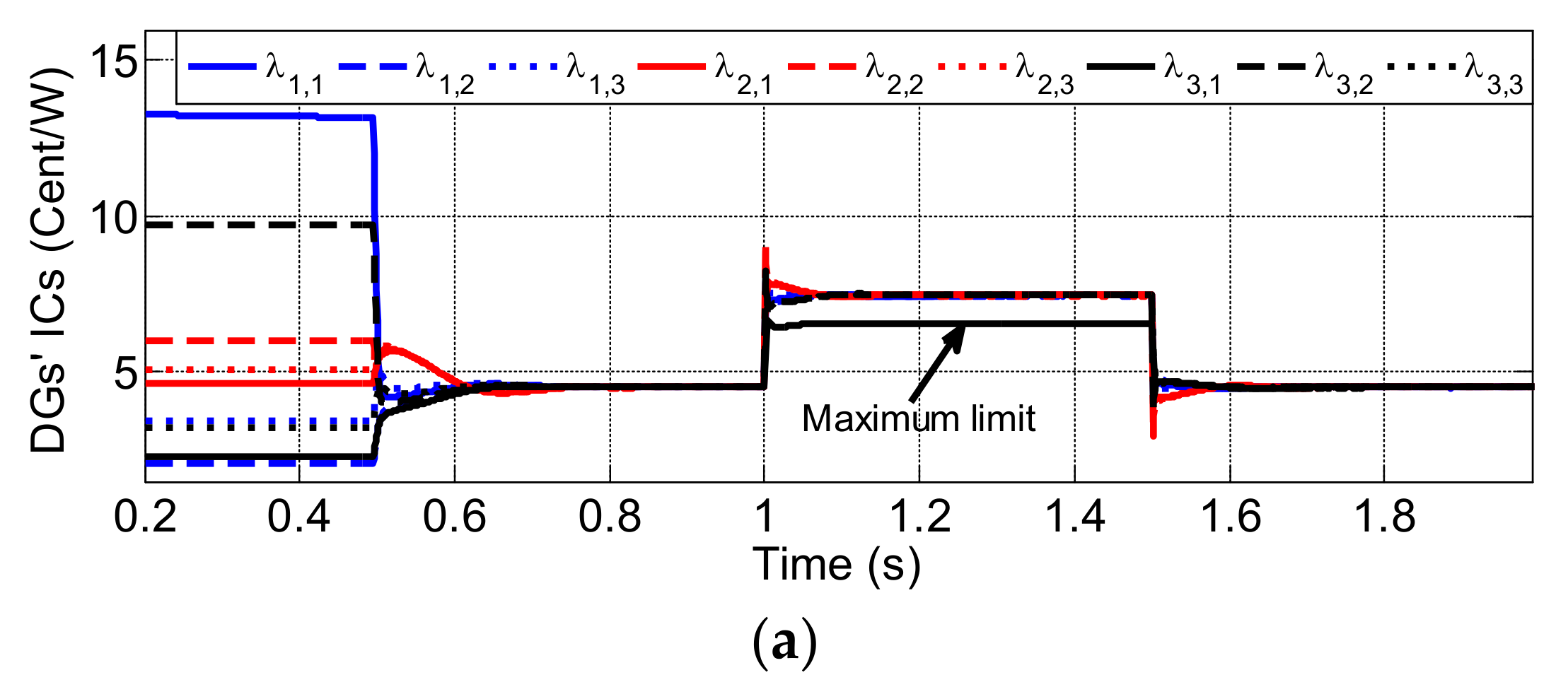
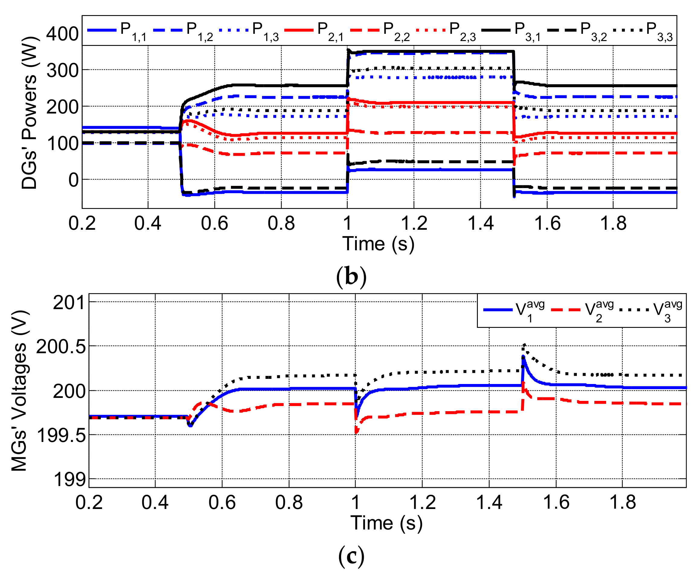
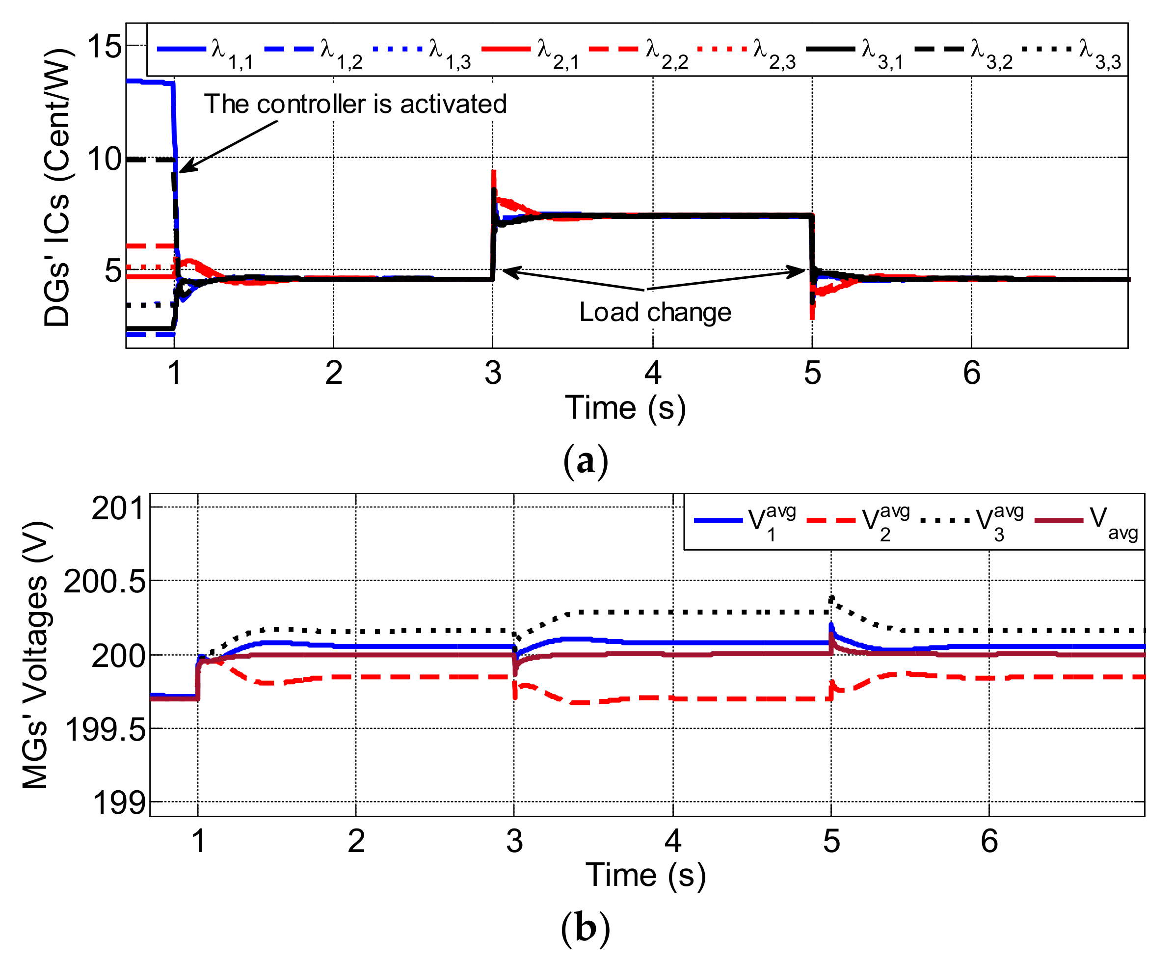
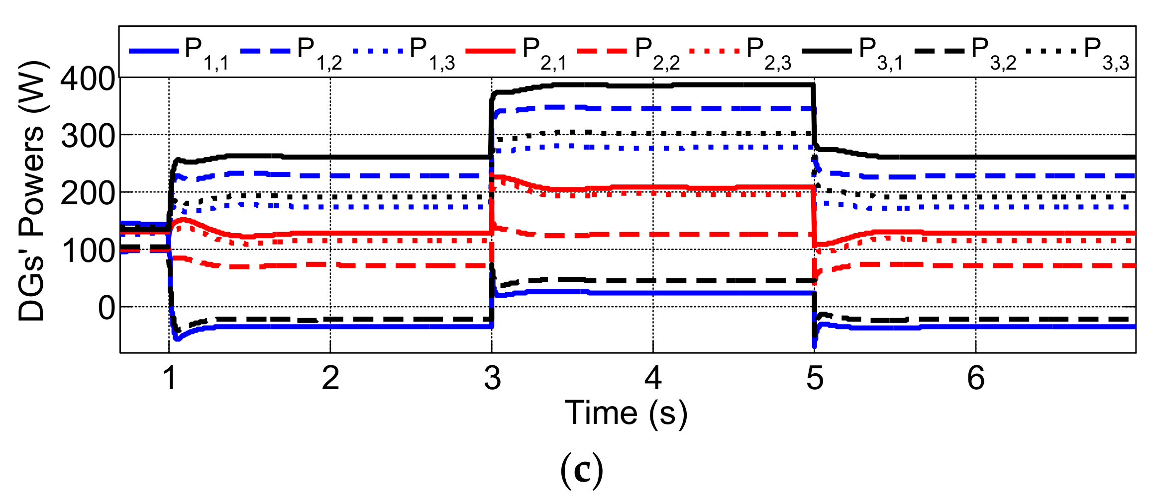
Figure 4 illustrates the robustness of the proposed control system under changed loading circumstances. Firstly, only the primary controller is activated; therefore, the DGs cover the required demand based on the droop control, which leads to a voltage deviation in MGs’ bus voltages due to the drooping gain, and the unmatched DGs’ ICs lead to high TGC. Then, the proposed local and global controllers are triggered at ; accordingly, the global TGC has effectively minimized, as the ICs of all DGs in all MGs are matched at the global optimal IC value, as seen in Figure 4a. The global controllers define MGs’ voltage references to guarantee the optimal exchanged power between them, as depicted in Figure 4b. Accordingly, the local controller regulates MG’s average voltages at the values given by the global controller. The average voltage across the DC multi-MGs is efficiently restored at 200 V, which reveals the power balance between generations and demands, as illustrated in Figure 4b. Furthermore, Figure 4c shows that the output powers of all DGs are optimally dispatched to supply the required loads, thanks to the equalized DGs’ ICs. Then, the effect of fluctuating demands on the proposed controller is studied by increasing/decreasing the total load. The proposed global controller tunes MGs’ reference voltages to achieve optimal operation and preserve the power balance of the DC multi-MGs, even with different loading conditions. Finally, it can be observed that, at the light loading period 0, BES units operate in the charging mode as the global IC of the cluster is low, while during the heavy loading period , they discharge to participate in supplying the extra loads, and their charging powers are optimally determined, as in Figure 4c.
4.2. Controller Performance with Considering EDP’s Inequality Constraint
Figure 5 demonstrates the performance of the developed finite-time controller while considering the EDP’s inequality constraint. At first, the proposed controller optimally allocates DGs’ output powers to cover the required demands by matching their ICs at a unique optimum value in a finite-time manner, as shown in Figure 5a,b. Then, the total load is increased at ; consequently, the proposed controller efficiently adjusts the production of each DG to supply the extra loads and attain generations-demands equilibrium within the predetermined constrained settling time. However, the output power of DG3,1 cannot be more than its maximum power 350 W, so it is omitted from the optimization problem and controlled to be at the limit, as illustrated in Figure 5b. Therefore, all DGs have equalized ICs, except DG3,1, whose IC value is adjusted at 6.53 ȼ/W, the value associated with the output power bound. Next, at , the total load is reduced, and the generations of all DGs are updated to supply the required demands optimally.
4.3. Comparative Study
Performance of the conventional asymptotic consensus-based control system [25], with an asymptomatic convergence manner compared to the proposed controller, is developed in this case study. Figure 6 depicts the performance of the multi-MGs, utilizing linear consensus with the identical operational conditions of case 4.1. It can be observed that the proposed controller matches all DGs’ ICs within a settling time of less than 0.15 s, while the linear consensus controller realizes the convergence within 0.85 s, as illustrated in Figure 4a and Figure 6a, respectively. It is revealed that the developed control scheme attains the controller objectives with a rapid operation in comparison with the traditional linear consensus-based controllers [25].
4.4. Plug-and-Play Feature
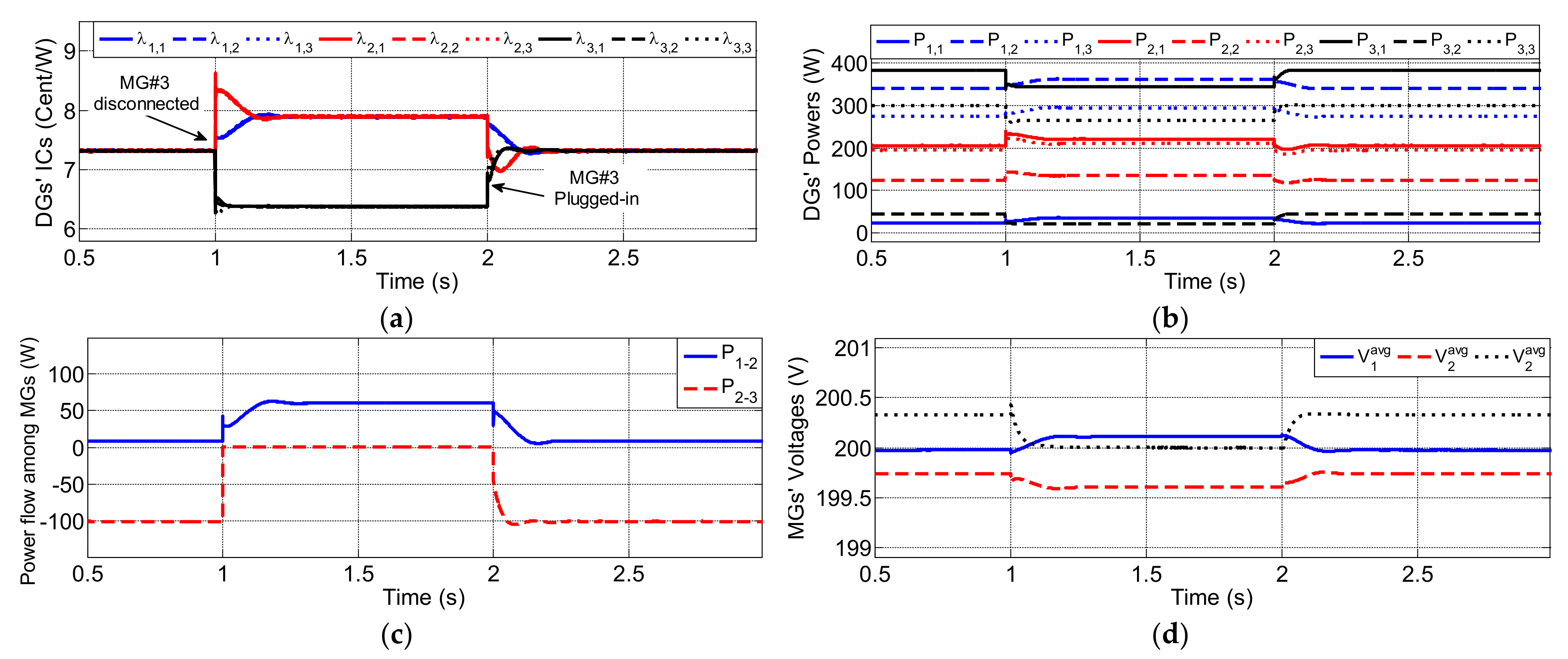
The plug-and-play capability of the proposed controller is demonstrated by either plugging in/out one MG or more to/from the cluster. Figure 7 depicts that the tested DC multi-MGs is operating at the lowest TGC until , when is disconnected electrically from the multi-MGs, and the related global communications links (link 2–3 and link 1–3) are lost. Therefore, the exchanged power between and becomes zero, as in Figure 7c. The interconnected and cooperate to cover their demands optimally, as the ICs of their DGs are equalized at a new optimum value, as seen in Figure 7a. It can be observed that operates in the islanded mode; accordingly, its DGs cover the local demand economically, as their ICs are equalized at the local optimal value. Furthermore, Figure 7d shows that its average voltage is restored at 200 V to maintain the local generations-demands power equilibrium. Finally, is reconnected to the cluster at ; hence, all MGs operate at the initial global optimal operating point with the lowest overall TGC.
4.5. Communication Link Failure Resiliency
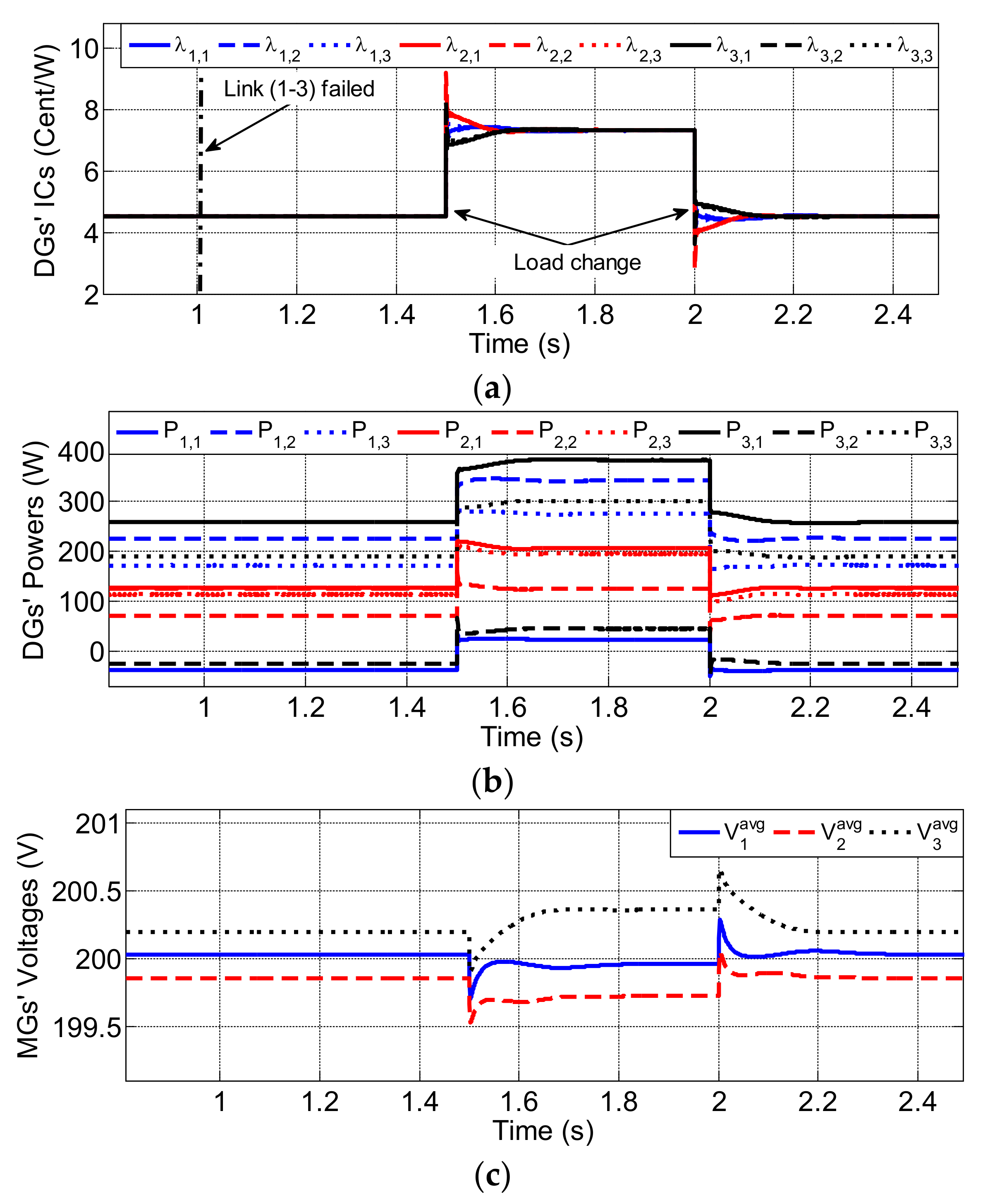
Cyber link failure is a non-avoidable feature of the distributed communication networks; therefore, this case study proves the resiliency of the proposed controller against losing cyber links, as shown in Figure 8. The upper cyber link (1–3) holding the information among and failed at , so the associated parts in the controller are disabled. Therefore, the global controllers of and compare their ICs with the one of , wherein the interconnected DC MGs economically cover the required demand, as all DGs’ ICs reach agreement despite the link failure, as shown in Figure 8a,b. Then, the required loads are increased at and decreased at to verify the efficacy of the proposed controller. The optimal operation is well maintained, but it can be noticed that the convergence time becomes a little longer than the convergence time without the link failure. The dynamic performance of the proposed controller with losing cyber link is still much better than the conventional linear consensus system. This study reveals that the developed control system is robust against cyber link failures.
4.6. Communication Delays
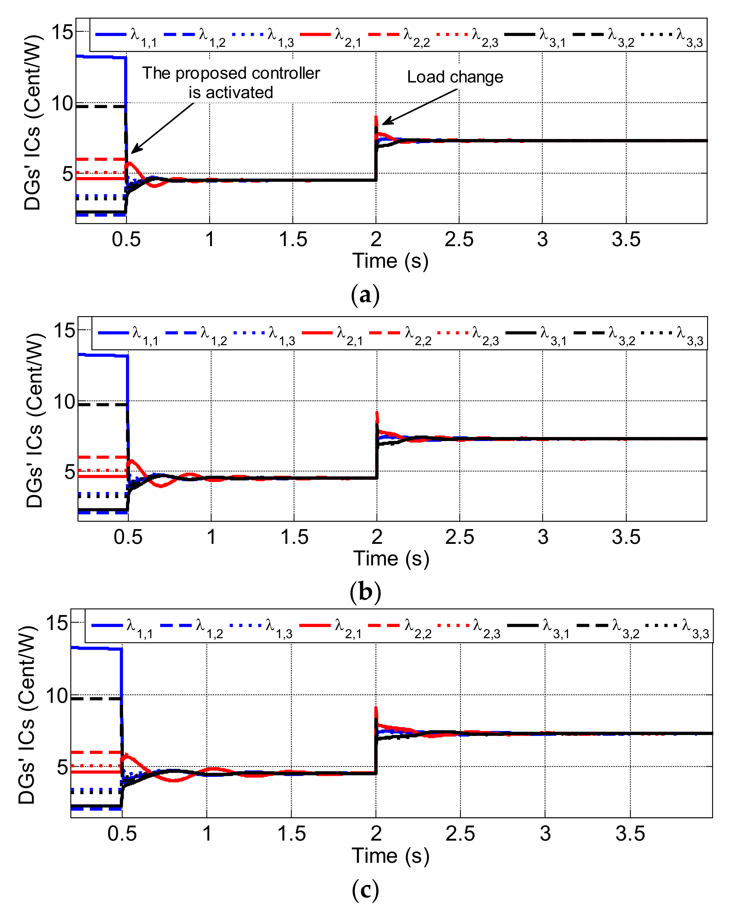
Next, performance of the proposed controller under different cyber delays, i.e., 50 ms, 100 ms, and 200 ms, is depicted in Figure 9. It can be noticed that, with 50 ms and 100 ms delays, DGs’ ICs are equalized at the desired global optimal value after a rapid fluctuations period, as seen in Figure 9a,b. Although longer cyber delays lead to larger oscillations and settling times, with cyber delays up to 200 ms, the fluctuations have been damped, and the controller goals are accomplished effectively.
4.7. Scalability Verification
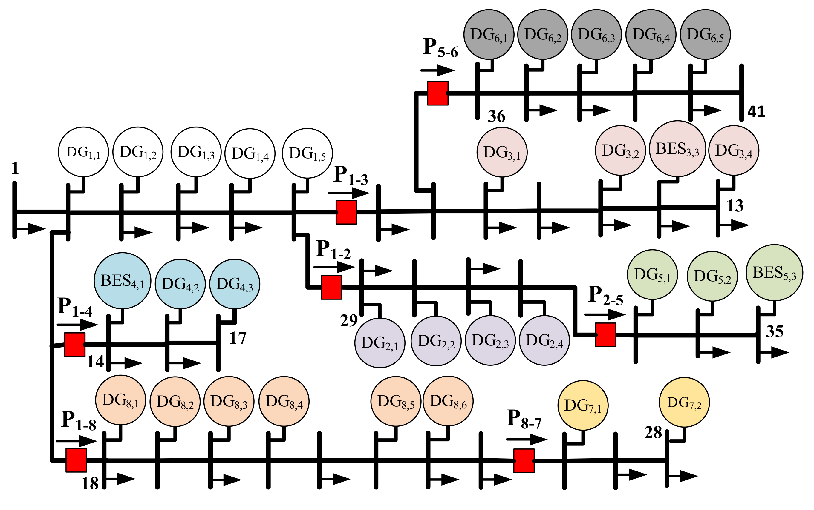
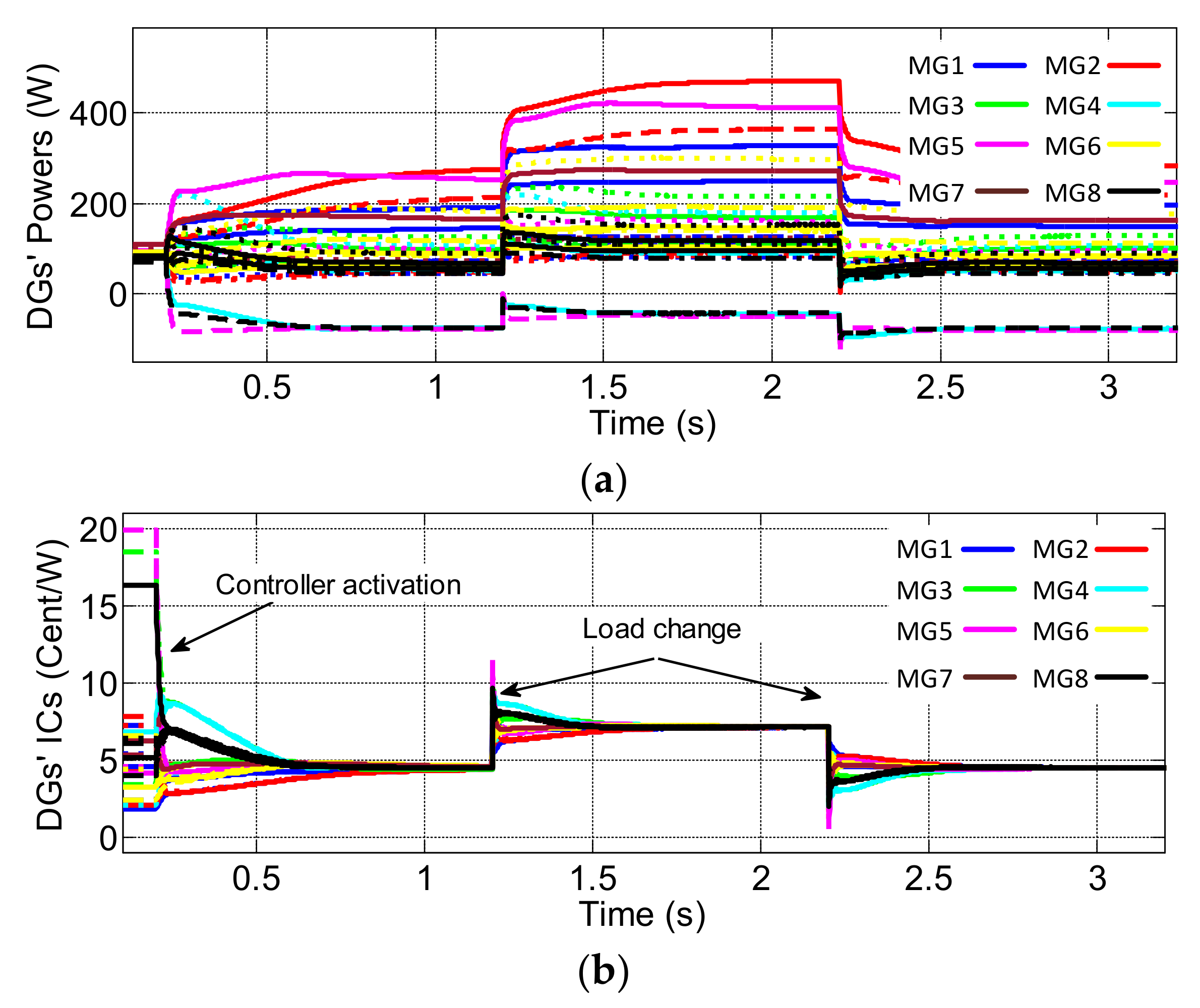
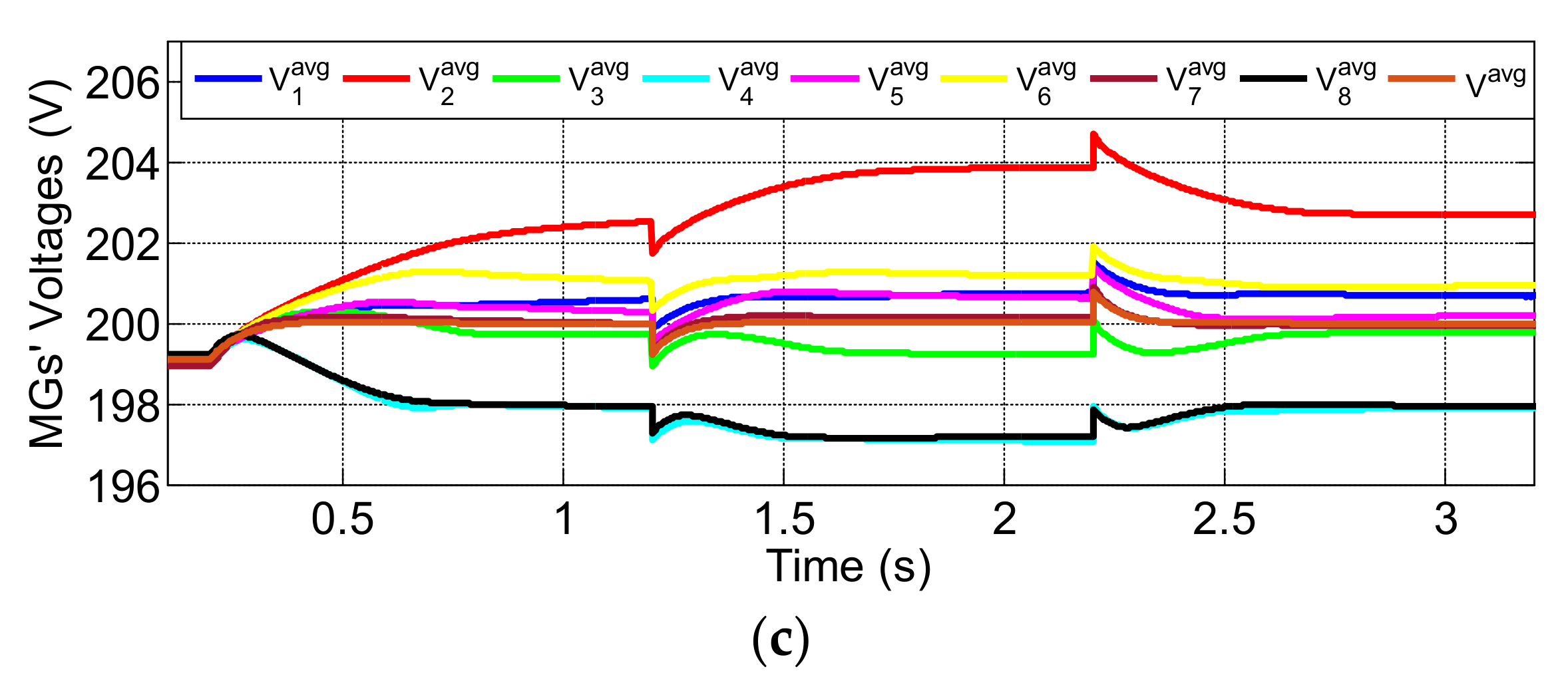
Figure 10 depicts the 41-node large-power system, consisting of eight interconnected DC MGs, which is developed to demonstrate the scalability feature of the developed control system, wherein the 200 V cluster includes 32 DCs connected through RL transmission lines. Parameters of all DGs’ generation costs are listed in Table 3.
Firstly, the proposed hierarchal control system is deactivated for , and only the primary controller is active. Therefore, it can be seen that DGs’ output powers are not optimized, as they cover the required demand based on droop control. There is also a voltage deviation in the average voltage across the DC multi-MGs, as shown in Figure 11b,c. Then, the developed controller is triggered at , and the ICs of all DGs within the interconnected DC MGs are synchronized at the optimum value to reduce the global TGC and optimize load sharing in a finite-time manner. Moreover, the average voltage across the multi-MGs is sufficiently restored at the desired value to guarantee the global generation-demand power balance. Finally, the extra load is added at and then removed at to prove the superiority of the proposed control system, as in Figure 11. It is clearly observed that the controller objectives are effectively accomplished in a finite-time manner, which proves that the proposed controller is valid even with a large-scale power system.
5. Conclusions
To realize a rapid optimal economic operation for DC multi-MGs with high penetration of renewables, a fully distributed finite-time control scheme has been developed in this paper. It involves local and global-control levels. Based on the finite-time consensus protocol, the global-control layer tunes the interconnected DC MGs’ voltage references to determine the optimal power flow between them and minimize the global TGC. Moreover, the local-control layer regulates MG’s average voltage at the value assigned by the global controller and matches the ICs of all DGs in each MG. Therefore, optimized loading dispatch among DGs, respecting T.L losses and fulfilling EDP’s equality and inequality constraints, can be realized. The optimal charging/discharging of the BES is considered for improving the global energy arbitrage of the DC multi-MGs. Simulation results prove the effectiveness of the proposed control scheme under different cases. It is observed that the proposed controller achieves a faster convergence manner compared to the existing linear consensus protocol. Further studies would be dedicated to improving the operation of the proposed distributed control strategy for considering line congestion and DG’s ramp rate limits in the optimization problem.
Author Contributions
Conceptualization, M.Z.; methodology, M.Z. and P.W.; software, M.Z.; validation, M.Z. and P.W.; formal analysis, M.Z.; investigation, M.Z. and P.W.; resources, P.W.; data curation, M.Z. and P.W.; writing—original draft preparation, M.Z. and P.W.; writing—review and editing, M.Z., P.W., W.W. and D.X.; visualization, P.W. and M.Z.; supervision, W.W. and D.X.; project administration, W.W. and D.X.; funding acquisition, P.W., W.W. and D.X. All authors have read and agreed to the published version of the manuscript.
Funding
This research was funded by China Postdoctoral Science Foundation grant number 2021T140155.
Institutional Review Board Statement
Not applicable for studies not involving humans or animals.
Informed Consent Statement
Not applicable.
Data Availability Statement
Not applicable.
Conflicts of Interest
The authors declare no conflict of interest.
References
- Al-Ismail, F.S. DC Microgrid Planning, Operation, and Control: A Comprehensive Review. IEEE Access 2021, 9, 36154–36172. [Google Scholar] [CrossRef]
- Dastgeer, F.; Gelani, H.E.; Anees, H.M.; Paracha, Z.J.; Kalam, A. Analyses of Efficiency/Energy-Savings of DC Power Distribution Systems/Microgrids: Past, Present and Future. Int. J. Electr. Power Energy Syst. 2019, 104, 89–100. [Google Scholar] [CrossRef]
- Han, Y.; Ning, X.; Yang, P.; Xu, L. Review of Power Sharing, Voltage Restoration and Stabilization Techniques in Hierarchical Controlled DC Microgrids. IEEE Access 2019, 7, 149202–149223. [Google Scholar] [CrossRef]
- Fotopoulou, M.; Rakopoulos, D.; Trigkas, D.; Stergiopoulos, F.; Blanas, O.; Voutetakis, S. State of the Art of Low and Medium Voltage Direct Current (DC) Microgrids. Energies 2021, 14, 5595. [Google Scholar] [CrossRef]
- Chen, B.; Wang, J.; Lu, X.; Chen, C.; Zhao, S. Networked Microgrids for Grid Resilience, Robustness, and Efficiency: A Review. IEEE Trans. Smart Grid 2021, 12, 18–32. [Google Scholar] [CrossRef]
- Al-Tameemi, Z.H.A.; Lie, T.T.; Foo, G.; Blaabjerg, F. Control Strategies of DC Microgrids Cluster: A Comprehensive Review. Energies 2021, 14, 7569. [Google Scholar] [CrossRef]
- Li, Z.; Shahidehpour, M.; Aminifar, F.; Alabdulwahab, A.; Al-Turki, Y. Networked Microgrids for Enhancing the Power System Resilience. Proc. IEEE 2017, 105, 1289–1310. [Google Scholar] [CrossRef]
- Wang, Z.; Chen, B.; Wang, J.; Chen, C. Networked Microgrids for Self-Healing Power Systems. IEEE Trans. Smart Grid 2016, 7, 310–319. [Google Scholar] [CrossRef]
- Meng, L.; Shafiee, Q.; Trecate, G.F.; Karimi, H.; Fulwani, D.; Lu, X.; Guerrero, J.M. Review on Control of DC Microgrids and Multiple Microgrid Clusters. IEEE J. Emerg. Sel. Top. Power Electron. 2017, 5, 928–948. [Google Scholar]
- Guerrero, J.M.; Vasquez, J.C.; Matas, J.; De Vicuña, L.G.; Castilla, M. Hierarchical Control of Droop-Controlled AC and DC Microgrids—A General Approach toward Standardization. IEEE Trans. Ind. Electron. 2011, 58, 158–172. [Google Scholar] [CrossRef]
- Bidram, A.; Davoudi, A. Hierarchical Structure of Microgrids Control System. IEEE Trans. Smart Grid 2012, 3, 1963–1976. [Google Scholar] [CrossRef]
- Gao, F.; Kang, R.; Cao, J.; Yang, T. Primary and Secondary Control in DC Microgrids: A Review. J. Mod. Power Syst. Clean Energy 2019, 7, 227–242. [Google Scholar] [CrossRef] [Green Version]
- Olivares, D.E.; Mehrizi-Sani, A.; Etemadi, A.H.; Cañizares, C.A.; Iravani, R.; Kazerani, M.; Hajimiragha, A.H.; Gomis-Bellmunt, O.; Saeedifard, M.; Palma-Behnke, R.; et al. Trends in Microgrid Control. IEEE Trans. Smart Grid 2014, 5, 1905–1919. [Google Scholar] [CrossRef]
- Han, H.; Hou, X.; Yang, J.; Wu, J.; Su, M.; Guerrero, J.M. Review of Power Sharing Control Strategies for Is-landing Operation of AC Microgrids. IEEE Trans. Smart Grid 2016, 7, 200–215. [Google Scholar] [CrossRef] [Green Version]
- Guerrero, J.M.; Chandorkar, M.; Lee, T.L.; Loh, P.C. Advanced Control Architectures for Intelligent Microgrids Part I: Decentralized and Hierarchical Control. IEEE Trans. Ind. Electron. 2013, 60, 1254–1262. [Google Scholar] [CrossRef] [Green Version]
- Espina, E.; Llanos, J.; Burgos-Mellado, C.; Cárdenas-Dobson, R.; Martínez-Gómez, M.; Sáez, D. Distributed Control Strategies for Microgrids: An Overview. IEEE Access 2020, 8, 193412–193448. [Google Scholar] [CrossRef]
- Han, Y.; Zhang, K.; Li, H.; Coelho, E.A.A.; Guerrero, J.M. MAS-Based Distributed Coordinated Control and Optimization in Microgrid and Microgrid Clusters: A Comprehensive Overview. IEEE Trans. Power Electron. 2018, 33, 6488–6508. [Google Scholar] [CrossRef] [Green Version]
- Shafiee, Q.; Dragičević, T.; Vasquez, J.C.; Guerrero, J.M. Hierarchical Control for Multiple DC-Microgrids Clusters. IEEE Trans. Energy Convers. 2014, 29, 922–933. [Google Scholar] [CrossRef] [Green Version]
- Moayedi, S.; Davoudi, A. Distributed Tertiary Control of DC Microgrid Clusters. IEEE Trans. Power Electron. 2016, 31, 1717–1733. [Google Scholar] [CrossRef]
- Han, R.; Tucci, M.; Martinelli, A.; Guerrero, J.M.; Ferrari-Trecate, G. Stability Analysis of Primary Plug-and-Play and Secondary Leader-Based Controllers for DC Microgrid Clusters. IEEE Trans. Power Syst. 2019, 34, 1780–1800. [Google Scholar] [CrossRef] [Green Version]
- Lu, X.; Lai, J. Distributed Cluster Cooperation for Multiple DC MGs over Two-Layer Switching Topologies. IEEE Trans. Smart Grid 2020, 11, 4676–4687. [Google Scholar] [CrossRef]
- Chen, Z.; Yu, X.; Xu, W.; Wen, G. Modeling and Control of Islanded DC Microgrid Clusters with Hierarchical Event-Triggered Consensus Algorithm. IEEE Trans. Circuits Syst. I Regul. Pap. 2021, 68, 376–386. [Google Scholar] [CrossRef]
- Jena, S.; Padhy, N.P.; Guerrero, J.M. Cyber-Resilient Cooperative Control of DC Microgrid Clusters. IEEE Syst. J. 2021. [Google Scholar] [CrossRef]
- Babazadeh-Dizaji, R.; Hamzeh, M. Distributed Hierarchical Control for Optimal Power Dispatch in Multiple DC Microgrids. IEEE Syst. J. 2020, 14, 1015–1023. [Google Scholar] [CrossRef]
- Zaery, M.; Wang, P.; Wang, W.; Xu, D. Distributed Global Economical Load Sharing for a Cluster of DC Microgrids. IEEE Trans. Power Syst. 2020, 35, 3410–3420. [Google Scholar] [CrossRef]
- Mudaliyar, S.; Duggal, B.; Mishra, S. Distributed Tie-Line Power Flow Control of Autonomous DC Microgrid Clusters. IEEE Trans. Power Electron. 2020, 35, 11250–11266. [Google Scholar] [CrossRef]
- Lu, X.; Lai, J.; Liu, G.-P. Master-Slave Cooperation for Multi-DC-MGs via Variable Cyber Networks. IEEE Trans. Cybern. 2021, 1–14. [Google Scholar] [CrossRef]
- Xu, Q.; Xu, Y.; Xu, Z.; Xie, L.; Blaabjerg, F. A Hierarchically Coordinated Operation and Control Scheme for DC Microgrid Clusters under Uncertainty. IEEE Trans. Sustain. Energy 2021, 12, 273–283. [Google Scholar] [CrossRef]
- Olfati-Saber, R.; Murray, R.M. Consensus Problems in Networks of Agents with Switching Topology and Time-Delays. IEEE Trans. Autom. Control. 2004, 49, 1520–1533. [Google Scholar] [CrossRef] [Green Version]
- Li, Y.; Dong, P.; Liu, M.; Yang, G. A Distributed Coordination Control Based on Finite-Time Consensus Algorithm for a Cluster of Dc Microgrids. IEEE Trans. Power Syst. 2019, 34, 2205–2215. [Google Scholar] [CrossRef]
- Wang, L.; Xiao, F. Finite-Time Consensus Problems for Networks of Dynamic Agents. IEEE Trans. Autom. Control. 2010, 55, 950–955. [Google Scholar] [CrossRef]
- Zaery, M.; Wang, P.; Wang, W.; Xu, D. Distributed finite-time controller for economic operation of dc multi-microgrids. In Proceedings of the IECON 2019—45th Annual Conference of the IEEE Industrial Electronics Society, Lisbon, Portugal, 14–17 October 2019; pp. 2154–2159. [Google Scholar]
- Zaery, M.; Wang, P.; Wang, W.; Xu, D. A Novel Fully Distributed Fixed-Time Optimal Dispatch of DC Multi-Microgrids. Int. J. Electr. Power Energy Syst. 2021, 129, 106792. [Google Scholar] [CrossRef]
- De Azevedo, R.; Cintuglu, M.H.; Ma, T.; Mohammed, O.A. Multiagent-Based Optimal Microgrid Control Using Fully Distributed Diffusion Strategy. IEEE Trans. Smart Grid 2017, 8, 1997–2008. [Google Scholar] [CrossRef]
- Zhou, C.; Qian, K.; Allan, M.; Zhou, W. Modeling of the Cost of EV Battery Wear Due to V2G Application in Power Systems. IEEE Trans. Energy Convers. 2011, 26, 1041–1050. [Google Scholar] [CrossRef]
- Zhang, Y.; Chow, M.Y. Microgrid Cooperative Distributed Energy Scheduling (CoDES) Considering Battery Degradation Cost. In Proceedings of the IEEE International Symposium on Industrial Electronics, Santa Clara, CA, USA, 8–10 June 2016; pp. 720–725. [Google Scholar]
- Soliman, S.A.-H.; Mantawy, A.-A.H. Modern Optimization Techniques with Applications in Electric Power Systems; Energy Systems; Springer: New York, NY, USA, 2012. [Google Scholar]
- Yang, S.; Tan, S.; Xu, J.X. Consensus Based Approach for Economic Dispatch Problem in a Smart Grid. IEEE Trans. Power Syst. 2013, 28, 4416–4426. [Google Scholar] [CrossRef]
- Qu, Z. Cooperative Control of Dynamical Systems: Applications to Autonomous Vehicles; Springer: London, UK, 2009. [Google Scholar]
- Bhat, S.P.; Bernstein, D.S. Finite-Time Stability of Continuous Autonomous Systems. SIAM J. Control. Optim. 2000, 38, 751–766. [Google Scholar] [CrossRef]
- Zuo, Z.; Tie, L. Distributed Robust Finite-Time Nonlinear Consensus Protocols for Multi-Agent Systems. Int. J. Syst. Sci. 2016, 47, 1366–1375. [Google Scholar] [CrossRef]
- Zhang, H.; Lewis, F.L.; Qu, Z. Lyapunov, Adaptive, and Optimal Design Techniques for Cooperative Systems on Directed Communication Graphs. IEEE Trans. Ind. Electron. 2012, 59, 3026–3041. [Google Scholar] [CrossRef]
Figure 1.
The Single-line diagram for DC-multi-MGs.

Figure 2.
The developed dual-layer finite-time control system.

Figure 3.
Schematic diagram of the simulated DC multi-MGs.

Figure 4.
Control system’s performance: (a) DGs’ incremental costs, (b) MGs average voltages, (c) DGs’ output powers, and (d) Global TGC.
Figure 4.
Control system’s performance: (a) DGs’ incremental costs, (b) MGs average voltages, (c) DGs’ output powers, and (d) Global TGC.

Figure 5.
Considering in-equality constraint: (a) DGs’ incremental costs, (b) MGs’ voltages, and (c) DGs’ powers.
Figure 5.
Considering in-equality constraint: (a) DGs’ incremental costs, (b) MGs’ voltages, and (c) DGs’ powers.


Figure 6.
Linear consensus control system: (a) DGs’ incremental costs, (b) MGs’ voltages, and (c) DGs’ generations.
Figure 6.
Linear consensus control system: (a) DGs’ incremental costs, (b) MGs’ voltages, and (c) DGs’ generations.


Figure 7.
Plug-and-play feature: (a) DGs’ incremental costs, (b) DGs’ generations, (c) Exchanged power between MGs, and (d) Average voltages across MGs.
Figure 7.
Plug-and-play feature: (a) DGs’ incremental costs, (b) DGs’ generations, (c) Exchanged power between MGs, and (d) Average voltages across MGs.

Figure 8.
Controller operation with cyber network failures: (a) DGs’ incremental costs, (b) DGs’ output powers, and (c) MGs’ average voltages.
Figure 8.
Controller operation with cyber network failures: (a) DGs’ incremental costs, (b) DGs’ output powers, and (c) MGs’ average voltages.

Figure 9.
The developed control system with cyber delays: (a) with 50 ms delay, (b) 100 ms delay, and (c) 200 ms delay.
Figure 9.
The developed control system with cyber delays: (a) with 50 ms delay, (b) 100 ms delay, and (c) 200 ms delay.

Figure 10.
Diagram of simulated 41-node large-scale power system.

Figure 11.
Scalability confirmation: (a) DGs’ output powers, (b) DGs’ incremental costs, and (c) Average voltages across the MGs.
Figure 11.
Scalability confirmation: (a) DGs’ output powers, (b) DGs’ incremental costs, and (c) Average voltages across the MGs.


Table 1.
Comparison of the Existing Power Management Control Strategies of DC Microgrids Cluster.
| Perspectives | [24] | [25] | [26] | [27] | [28] | [30] | [32] | [33] | Proposed |
|---|---|---|---|---|---|---|---|---|---|
| Fully distributed Scheme | √ | √ | √ | √ | √ | √ | √ | √ | |
| Rapid convergent rate | √ | √ | √ | √ | |||||
| Optimal load scheduling | √ | √ | √ | √ | √ | √ | √ | √ | √ |
| Generation-demand balance | √ | √ | √ | √ | √ | √ | √ | √ | √ |
| DGs power limits | √ | √ | √ | √ | √ | √ | √ | √ | |
| T.L losses minimization | √ | √ | √ | ||||||
| BES economic operation | √ | ||||||||
| MG’s Plug-and-Play capability | √ | √ | √ | √ | √ | √ | √ | √ | √ |
| Cyber losses resiliency | √ | √ | √ | √ | √ | √ | √ | √ | |
| Cyber delays resiliency | √ | √ | √ | √ | √ | √ | √ |
Table 2.
Parameters of The Tested DC Multi-MGs.
| DGs’ Production Costs | |||||
|---|---|---|---|---|---|
| 110 | 0.95 | 0.022 | 80 | ||
| 75 | 0.55 | 0.007 | 500 | ||
| 85 | 0.62 | 0.01 | 400 | ||
| 90 | 0.65 | 0.014 | 350 | ||
| 120 | 0.98 | 0.024 | 300 | ||
| 95 | 0.91 | 0.015 | 450 | ||
| 60 | 0.5 | 0.006 | 330 | ||
| 100 | 0.93 | 0.019 | 90 | ||
| 80 | 0.61 | 0.009 | 550 | ||
| Transmission Lines Factors | |||||
| T.L | |||||
| Local | 0.6 | 50 | 30 | ||
| Global | 1.2 | 100 | 60 | ||
| Dual-Layer Control System Parameters | |||||
| 10 | 10 | 2 | 0.6 | 0.6 | |
Table 3.
The 41-node power system’s DGs Generation Costs.
| 0.6 | 0.75 | 0.91 | 0.8 | 0.55 | 0.51 | 0.54 | 0.9 | |
| 0.013 | 0.025 | 0.038 | 0.029 | 0.01 | 0.007 | 0.009 | 0.037 | |
| 0.87 | 0.67 | 0.84 | 0.63 | 0.8 | 0.95 | 0.88 | 0.66 | |
| 0.034 | 0.019 | 0.032 | 0.015 | 0.029 | 0.014 | 0.035 | 0.018 | |
| 0.53 | 0.69 | 0.98 | 0.71 | 0.65 | 0.57 | 0.73 | 0.82 | |
| 0.008 | 0.02 | 0.044 | 0.022 | 0.017 | 0.011 | 0.023 | 0.031 | |
| 0.58 | 0.76 | 0.78 | 0.94 | 0.7 | 0.94 | 0.85 | 0.79 | |
| 0.012 | 0.026 | 0.027 | 0.04 | 0.021 | 0.039 | 0.033 | 0.029 |
Publisher’s Note: MDPI stays neutral with regard to jurisdictional claims in published maps and institutional affiliations. |
© 2022 by the authors. Licensee MDPI, Basel, Switzerland. This article is an open access article distributed under the terms and conditions of the Creative Commons Attribution (CC BY) license (https://creativecommons.org/licenses/by/4.0/).
Share and Cite
MDPI and ACS Style
Zaery, M.; Wang, P.; Wang, W.; Xu, D. A Novel Optimal Power Allocation Control System with High Convergence Rate for DC Microgrids Cluster. Energies 2022, 15, 3994. https://0-doi-org.brum.beds.ac.uk/10.3390/en15113994
AMA Style
Zaery M, Wang P, Wang W, Xu D. A Novel Optimal Power Allocation Control System with High Convergence Rate for DC Microgrids Cluster. Energies. 2022; 15(11):3994. https://0-doi-org.brum.beds.ac.uk/10.3390/en15113994
Chicago/Turabian StyleZaery, Mohamed, Panbao Wang, Wei Wang, and Dianguo Xu. 2022. "A Novel Optimal Power Allocation Control System with High Convergence Rate for DC Microgrids Cluster" Energies 15, no. 11: 3994. https://0-doi-org.brum.beds.ac.uk/10.3390/en15113994
Note that from the first issue of 2016, this journal uses article numbers instead of page numbers. See further details here.