
Modeling and Analysis of the Flow Characteristics of Liquid Hydrogen in a Pipe Suffering from External Transient Impact

1
State Key Laboratory of Technologies in Space Cryogenic Propellants, Beijing 100028, China
2
Department of Building Environment and Energy Application Engineering, School of Mechanics and Civil Engineering, China University of Mining and Technology, Xuzhou 221116, China
*
Author to whom correspondence should be addressed.
Energies 2022, 15(11), 4154; https://0-doi-org.brum.beds.ac.uk/10.3390/en15114154
Submission received: 1 May 2022
/
Revised: 3 June 2022
/
Accepted: 3 June 2022
/
Published: 5 June 2022
(This article belongs to the Special Issue Computational Fluid Dynamics Applied to Hydrogen Safety)
Abstract
:Pipes can be subjected to external transient impacts such as accidental collision, which affects the safe operation of storage and transportation systems for liquid hydrogen. Fluid–structure coupling calculation for a pipe under external transient impact is performed, and the flow characteristics of liquid hydrogen in the pipe are analyzed. The pipe deforms and vibrates when suffering from external transient impact. Liquid hydrogen pressure in a cross-section plane increases along the pipe deformation direction. Additionally, external transient impact enhances the disturbance of liquid hydrogen near the pipe wall. The increased flow resistance and the energy induced by the deformed pipe both affect the flow of liquid hydrogen, and contribute to the fluctuated characteristics of liquid pressure drop. In addition, the phase state of liquid hydrogen remains unchanged in the pipe, indicating that little of the induced energy is transformed into the internal energy of liquid hydrogen. The work provides theoretical guidance for the safe operation of liquid hydrogen storage and transportation systems.
1. Introduction
Liquid hydrogen, which has been widely used as space cryogenic propellant [1], has the advantages of high gravimetric and volumetric energy densities [2], environmental friendliness and renewability. Moreover, hydrogen energy is considered as a future energy and exhibits promising application potentials in fuel cells and vehicles [3,4]. The flow characteristics of liquid hydrogen in pipes are vital for the safe and stable operation of storage and transportation systems. However, the pipe could be subjected to external transient impacts such as accidental collision, which affects the dynamics behavior of the pipe and the flow characteristics of liquid hydrogen in the pipe. In particular, when the external transient impact exceeds a certain strength, the pipe can even break and fail, resulting in the leakage of liquid hydrogen into the surrounding environment, and the safety of personnel and equipment is seriously threatened [5].
In past decades, great efforts have been dedicated to investigations regarding the leakage and dispersion of liquid hydrogen, caused by the rupture of pipes or storage vessels. The National Aeronautics and Space Administration (NASA) in the USA [6], the Federal Institute for Materials Research and Testing (BAM) in Germany [7] and the Health and Safety Laboratory (HSL) in the UK [8] have carried out liquid hydrogen spill experiments in open environments, between buildings and under pipe failure conditions, respectively. Verfondern et al. [9] conducted liquid hydrogen pool spread experiments on the surface of water and solid ground. Due to the huge cost and the safety issues related to the experiment, many researchers also investigated the leakage and dispersion of liquid hydrogen numerically [10,11,12,13,14,15,16,17,18,19,20,21], which revealed the underlying mechanisms and the effects of various conditions, such as spill source, season, wind flow, air humidity, etc.
However, there is little research focused on the flow characteristics of liquid hydrogen in a pipe subjected to an external transient impact. Instead, the flow and heat transfer of fluid in a pipe under vibration excitation has been reported in the literature. Liu et al. [22] experimentally studied the influence of sinusoidal vibration on the heat transfer characteristics of circular pipes and found that vibration could significantly affect the heat transfer process. Tian et al. [23] applied lateral vibration on a pipe and found that the wall heat transfer was significantly strengthened due to the rapid growth of the thermal boundary layer. For cryogenic fluid, Zheng et al. [24] numerically studied the influence of wall vibration on the boiling flow and heat transfer of liquid hydrogen in a horizontal pipe. The vibration of a circular pipe could enhance the heat transfer intensity between liquid hydrogen and the wall, and the enhancement is more obvious at a lower inlet velocity. Chen et al. [25] studied the influence of vibration on the filling process of liquid hydrogen in a horizontal circular pipe. The increase in vibration frequency and amplitude enhances the heat exchange between liquid hydrogen and the pipe, while the vibration destroys the stable boundary of two-phase flow and promotes the bubble separation, which affects the stability of the transportation system. The external transient impact and the vibration could both be classified as the external excitation. However, compared with vibration, the transient impact commonly has an extremely short duration and high intensity, which will cause the deformation of the pipe and energy input to the liquid flow.
Consequently, it is essential to carry out research on the flow characteristics of liquid hydrogen in a pipe suffering from an external transient impact. In the present work, a three-dimensional computational fluid dynamics (CFD) model predicting the flow of liquid hydrogen in a pipe is first designed and validated. Then, the fluid–structure coupling calculation for the pipe under external transient impact is performed in ANSYS Workbench 14.5 (ANSYS, Inc., Canonsburg, PA, USA). Finally, the flow characteristics of liquid hydrogen in the pipe under external transient impact are analyzed. The work provides theoretical guidance for the safe operation of liquid hydrogen storage and transportation systems, which could help to promote the smooth progress of space launch missions and the applications of hydrogen in fuel cells and vehicles, as well as ensuring the safety of personnel and equipment.
2. CFD Model Predicting the Flow of Liquid Hydrogen in a Pipe
2.1. Mathematical Model
The mixture multiphase model is adopted to predict the flow of liquid hydrogen in a pipe, and the conservation equations for mixture mass, mixture momentum and mixture enthalpy are:
where ρ, v and μ are density, velocity and kinetic viscosity, respectively. keff is the effective conductivity coefficient, vdr,i is the drift velocity for phase i and α is the volume fraction. The subscripts m, l and g represent the mixture phase, the liquid phase and the vapor phase, respectively. The physical properties of hydrogen and liquid hydrogen are calculated in terms of temperature in the present work, and the corresponding data are acquired from NIST REFPROP (National Institute of Standards and Technology, Gaithersburg, MD, USA) [26]. The mixture properties are calculated by the following equations:
The phases move with different velocities, and the slip velocity is expressed as [27]:
where the drag force is
The Lee model [28] is used to simulate the liquid–vapor phase change and mass transfer process for hydrogen:
where and are the mass transfer rates due to evaporation and condensation, respectively. The coefficients γev and γcon are specified as 0.25 s−1 for the phase change of hydrogen [18]. The liquid phase and the vapor phase are in thermal equilibrium state with the same temperature.
The realizable k-ε model [29] is adopted for turbulent closure:
where , , . Gk and Gb are the generation of turbulence kinetic energy due to the mean velocity gradients and the buoyancy, respectively. In addition, standard wall functions are adopted for the near-wall treatment.
2.2. Model Validation
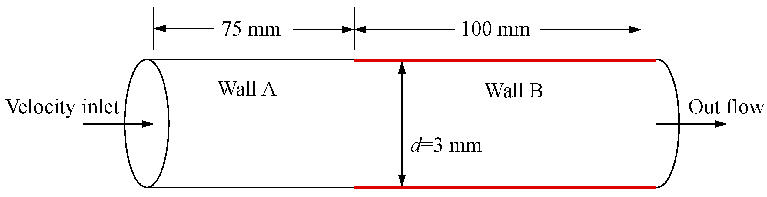
The experimental data from Tatsumoto et al. [30] for liquid hydrogen flow in a pipe under low wall superheat conditions are used to validate the reliability of the developed model. Figure 1 illustrates the calculation domain for the flow of liquid hydrogen in a horizontal pipe schematically. The inner diameter of the pipe is 3 mm. The lengths of walls labeled with A and B are 75 mm and 100 mm, respectively. The wall labeled A is adiabatic. The wall labeled B is heated by a heater, and a temperature difference exists between the pipe wall and liquid hydrogen. Liquid hydrogen in saturated state (with the pressure and temperature of 0.7 MPa and 29 K) enters the pipe from the left plane, while the outlet (the right plane) is specified as out-flow boundary condition. The flow is composed of liquid hydrogen only at the entrance. The velocities of liquid hydrogen are 4.75 m/s, 16.7 m/s and 31.5 m/s, respectively.
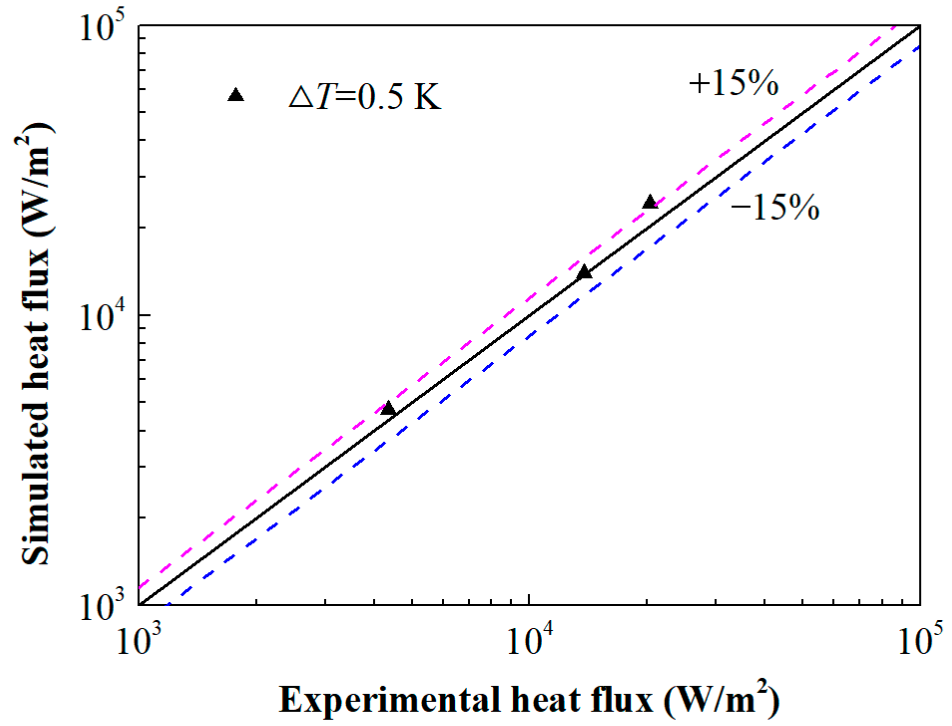
Figure 2 shows the comparison between the simulation results and the experiment, where ΔT is the temperature difference between the pipe wall and the liquid hydrogen. It can be seen that the simulation result and the experimental data are basically consistent, with the maximum relative error less than 15%. The complex two-phase flow and phase change behaviors of liquid hydrogen, and the negligible sensor errors in the experiment, contribute to the deviation between the simulation and experiment. It is considered that the developed model in the paper could be used to simulate the flow and heat transfer of liquid hydrogen in the pipe under low wall superheat conditions.
3. Calculation Strategy for the Fluid–Structure Coupling of the Pipe under External Transient Impact
3.1. Physical Model
Pipes for transportation of cryogenic fluid commonly have a double-layer structure, and there is a thermal insulation layer outside the pipe, so as to reduce the heat exchange with the surrounding environment. The outer wall of the pipe is first subjected to the external transient impact and the impact strength is reduced. However, if the external transient impact is strong enough, the double-layer structure of the pipe can be ruptured and fail. In the present work, the pipe is simplified as a single-layer structure under the transient impact which has been attenuated by the outer layer. The inner diameter, wall thickness and length of the pipe are 100 mm, 2.5 mm and 3 m, respectively. The pipe material is austenitic stainless steel. The density, Young’s modulus, Poisson ratio, yield strength and tensile strength of the selected material are, respectively, 7860 kg/m3, 210 GPa, 0.279, 1615 MPa and 1950 MPa [31].
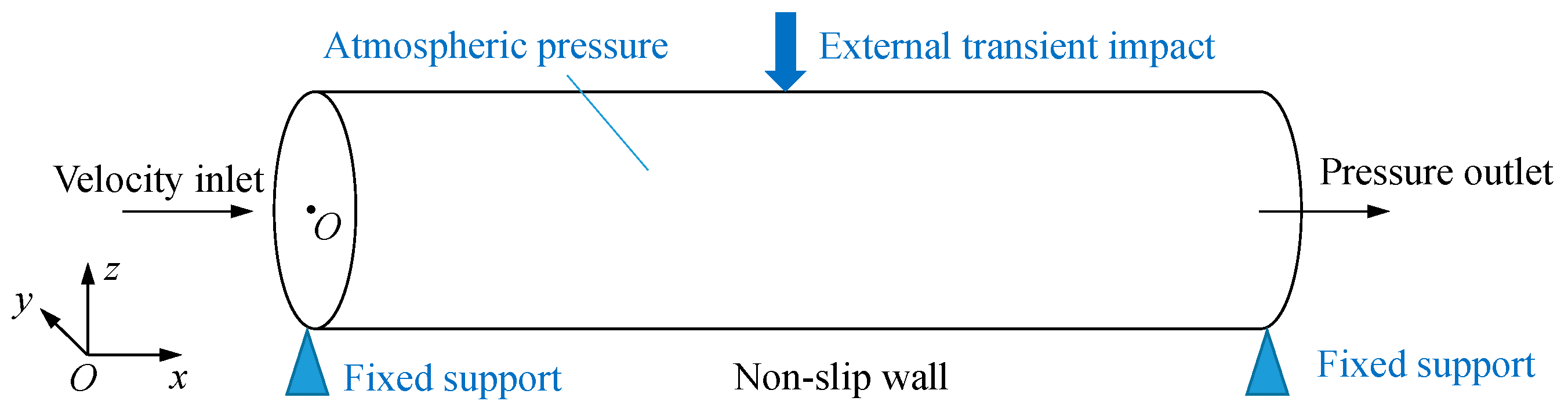
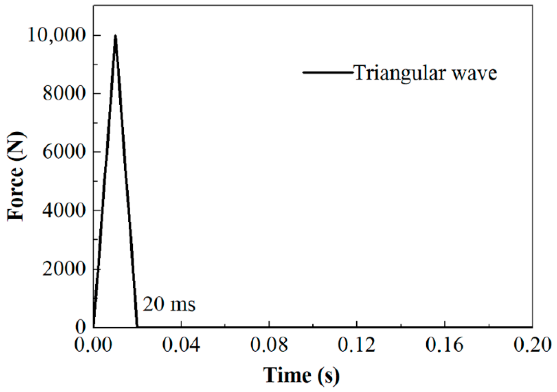
A physical model for the fluid–structure coupling is illustrated in Figure 3. For the solid domain, SOLID187 is used for the finite element modeling. SOLID187 is defined by 10 nodes, and has three degrees of freedom at each node. It has plasticity, hyper elasticity, creep, stress stiffening, large deflection and large strain capabilities [32]. Both the entrance (left plane) and the exit (right plane) of the pipe are set as fixed support, which are prevented from moving and deforming. The surface of the pipe is subjected to atmospheric pressure (101,325 Pa), and the center of the pipe is subjected to the external transient impact which is perpendicular to the surface. The commonly used external impact curve includes triangular wave, semi-sinusoidal wave, etc. [33], with the duration in milliseconds. In fact, the semi-sinusoidal wave and the triangular wave are approaching, especially when the duration is short and the intensity is high. In the present work, the external transient impact is characterized by a triangular wave, with a duration of 20 ms and a peak of 10,000 N, as shown in Figure 4. It resembles the impact by a falling rock with a mass of 10 kg and a velocity of 7 m/s (the amplification factor = 2, and normal recovery coefficient = 0.42) [34]. Liquid hydrogen enters the pipe with a velocity of 8 m/s and a temperature of 20.35 K, while the outlet pressure is set as 101,325 Pa. The internal pressure of the pipe is above 101,325 Pa which varies with location due to the flow resistance, and liquid hydrogen is slightly subcooled in the pipe. The viscosity of liquid hydrogen at the outlet is 1.33×10⁻⁵ Pa·s [26], and the Reynolds number is 60,150, which indicates turbulent flow. As the heat loss of a well-insulated cryogenic pipe is commonly less than 1 W/m [35], the leaked heat energy through the pipe is relatively low, especially when compared with the energy induced by the external transient impact, and the wall is considered adiabatic and heat transfer with the environment is neglected. In addition, the wall is non-slip.
3.2. Calculation Method
The fluid–structure coupling calculation is performed in ANSYS Workbench 14.5. The fluid flow module is solved by ANSYS Fluent, while the transient force module is solved by Mechanical APDL (ANSYS, Inc., Canonsburg, PA, USA). The data are transmitted between the two modules through the fluid–structure coupling surface (i.e., pipe wall adjacent to the fluid) in the system coupling module. The flow of liquid hydrogen is calculated firstly, and the fluid pressure is transmitted to the transient analysis module. Then, the transient force calculation is performed and the displacement data are transformed to the flow calculation module. The convergence target for the data transfer control is 10−3. The step size is 0.001 s. The external transient impact is applied at 0.7 s when the flow is already steady, and the total simulation time is 1.3 s. The time in the following analysis is set as 0 when the external transient impact is applied. Specifically, for fluid flow calculation, the PISO algorithm is chosen for pressure–velocity coupling, and the standard scheme is used for pressure. A second-order upwind scheme is adopted to solve the momentum, volume fraction, turbulent kinetic energy, turbulent dissipation rate and energy equations. The standard initialization method is chosen. Time step for the flow calculation is also 0.001 s, and the convergence criterion is 10−4.
3.3. Computational Mesh and Mesh Independency Test
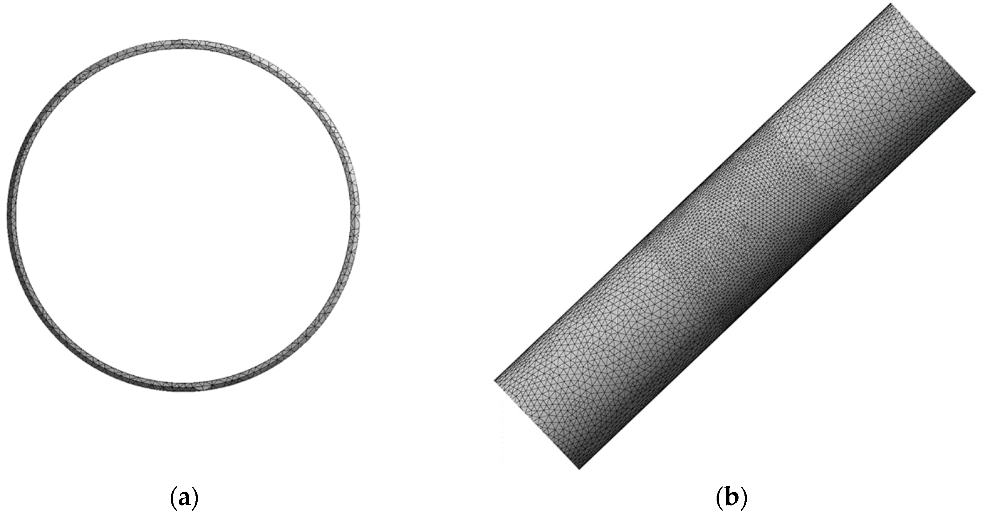
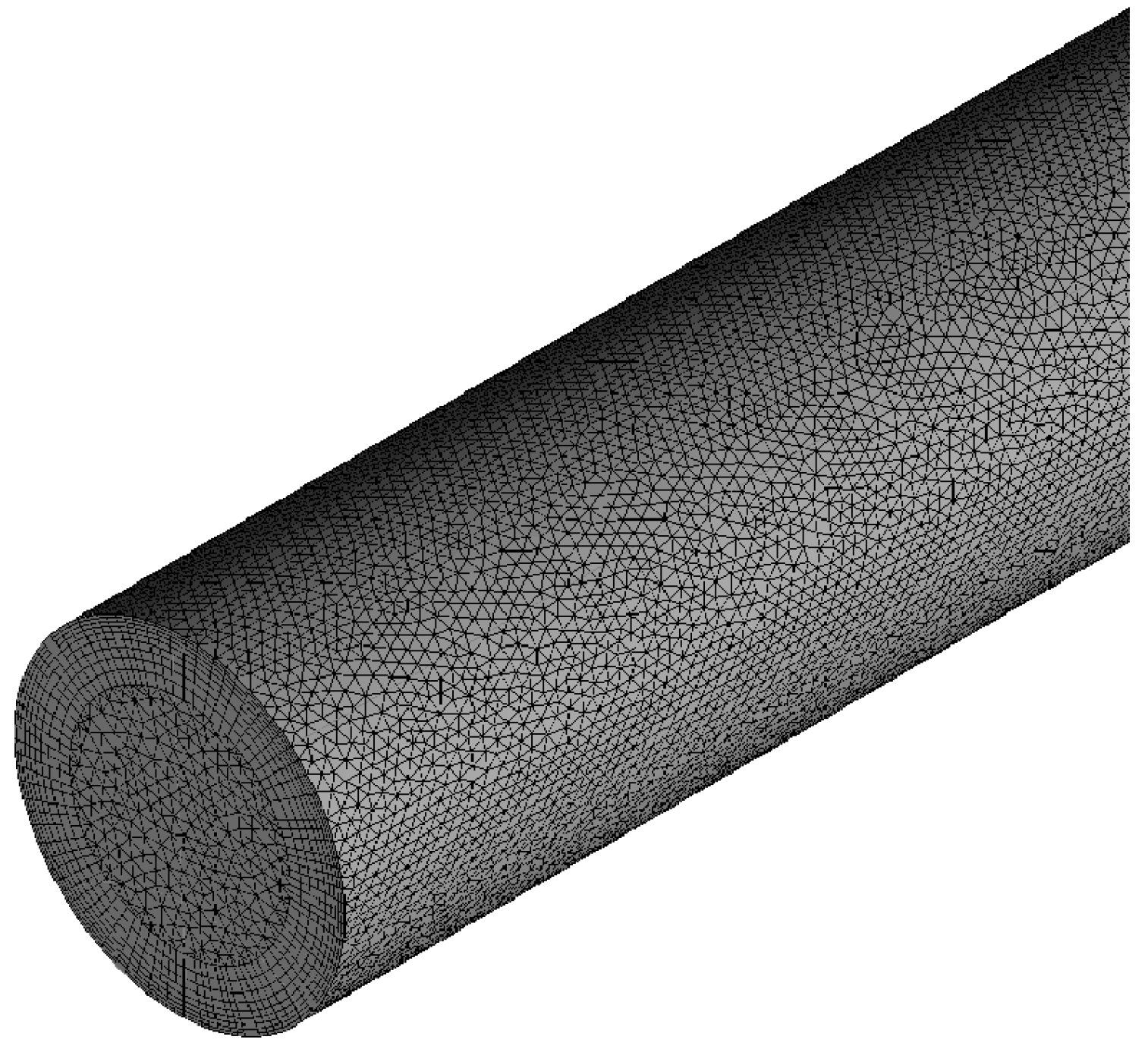
Computational meshes for the numerical analysis are shown in Figure 5 and Figure 6. For the solid domain, mesh is locally refined near the impact region. For the fluid domain, unstructured mesh is generated, and is also locally refined near the impact region, with a minimum mesh size of 0.0004 m, a maximum size of 0.006 m and a growth rate of 1.20. The moving-grid model is used for flow calculation due to the deformation of the calculation domain. Smoothing and remeshing methods are adopted for the dynamic mesh with implicit updating. The entrance and outlet of the pipe are stationary, the interior-fluid zone is deforming, and the pipe wall is system coupling.
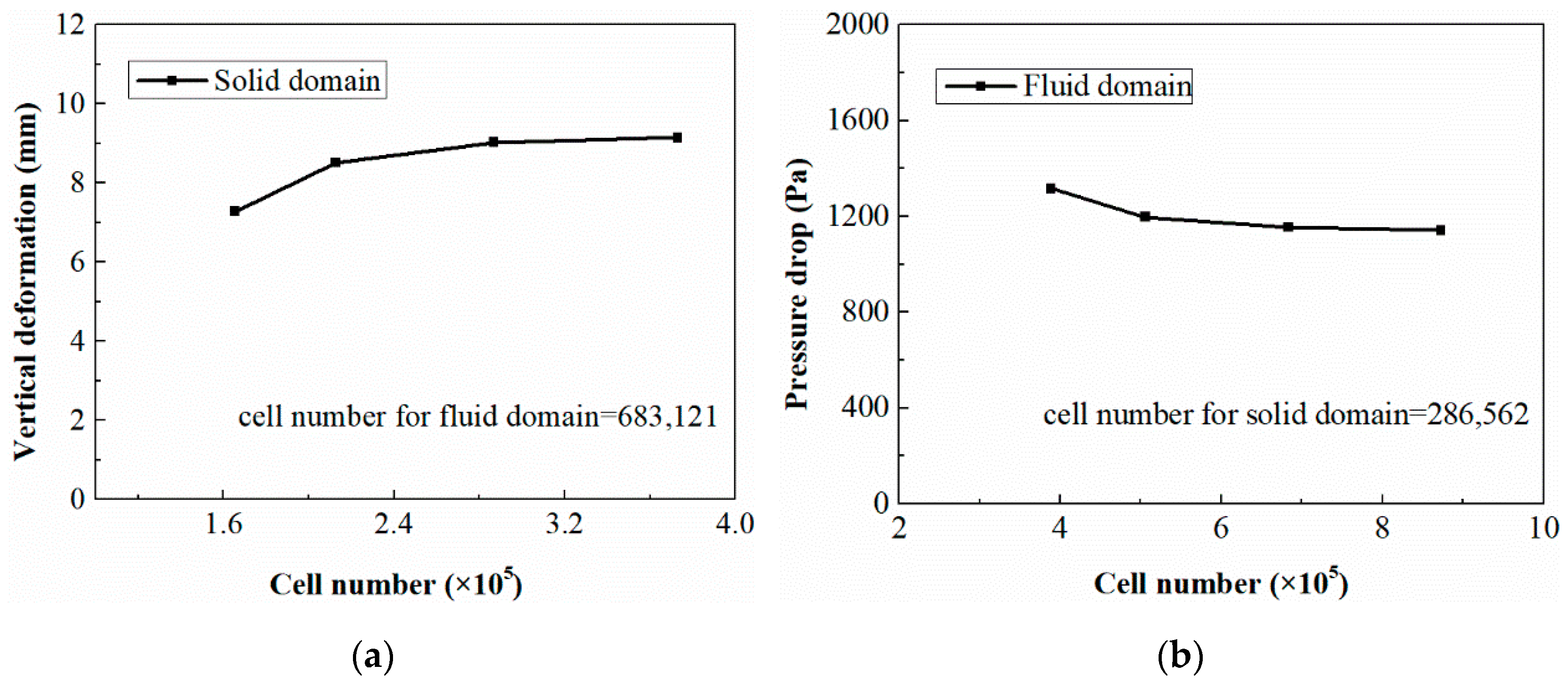
Mesh independency tests are conducted to ensure that the numerical results are independent of mesh size, and the results are illustrated in Figure 7. The vertical deformation of the impact point along the -z direction at 0.01 s and the pressure drop between the entrance and the exit of the pipe at 0.01 s are the variables selected for comparison. It can be seen that the relative deviation of the pipe vertical deformation calculated at 286,562 cells from that at 372,865 cells (for the solid domain) is 1.31%, and the relative deviation of the pressure drop calculated at 683,121 cells from that at 872,563 cells (for the fluid domain) is −1.05%. Considering the mesh independency and the computation efficiency, the mesh with 286,562 cells for the solid domain and the mesh with 683,121 cells for the fluid domain are chosen.
4. Flow Characteristics of Liquid Hydrogen in the Pipe under External Transient Impact
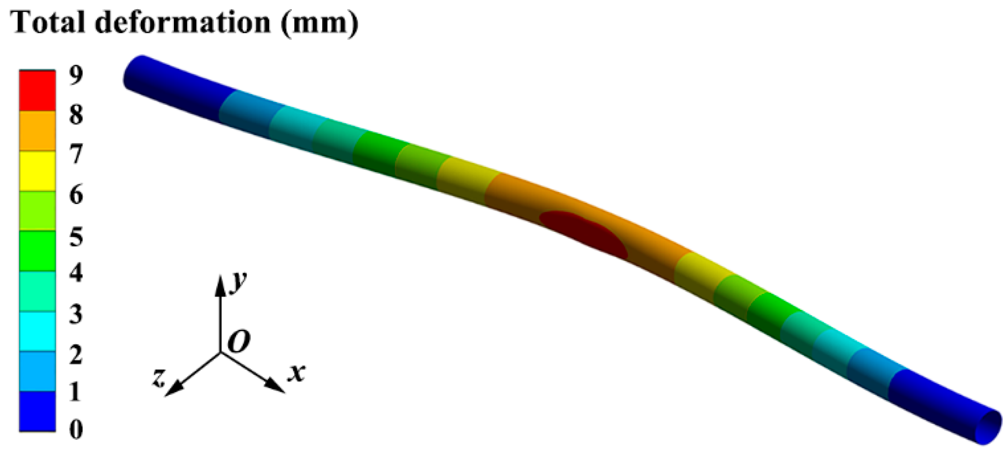
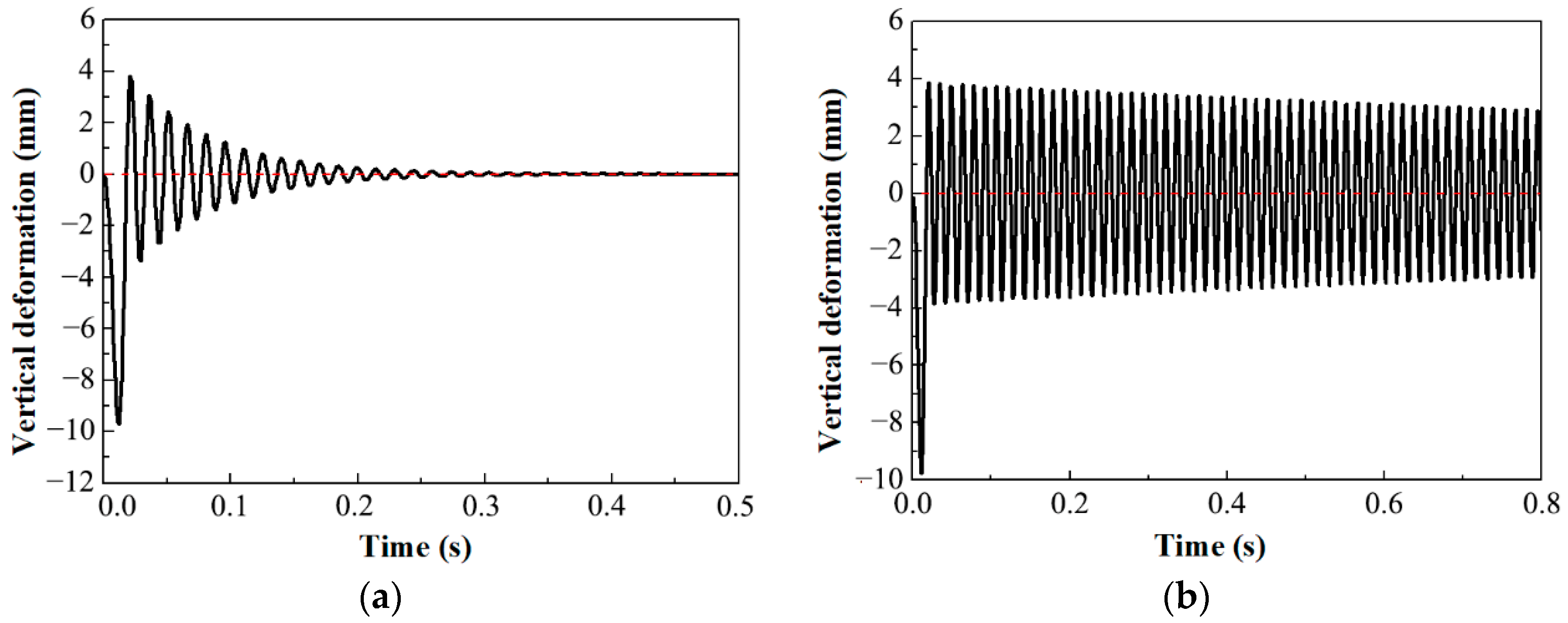
Dynamics behavior of the pipe which influences the flow of liquid hydrogen is firstly observed. The total deformation of the pipe at 0.01 s with liquid hydrogen inside is shown in Figure 8. The vertical deformations of the impact point with and without liquid hydrogen in the pipe are shown in Figure 9. The time “0” corresponds to the time when the impact is applied and not to the actual simulation time. It can be seen that the pipe will deform and vibrate when suffering from external transient impact. Compared with the condition of no fluid in the pipe, the maximum amplitude decreases slightly from 9.78 mm to 9.70 mm when there is fluid. Additionally, with fluid in the pipe, the vibration amplitude of the pipe attenuates rapidly, and the positive amplitude attenuates to 6.9% of the maximum amplitude 0.2 s after the transient impact. The pipe vibration becomes unobvious 0.3 s after the transient impact. On the contrary, when no fluid exists in the pipe, the amplitude of pipe vibration decreases slowly with time and, even 0.8 s after the impact, it has not attenuated. It can be concluded that energy induced by the external transient impact is dissipated by both the pipe and the fluid. Moreover, the energy dissipation by the fluid is higher than that by the pipe.
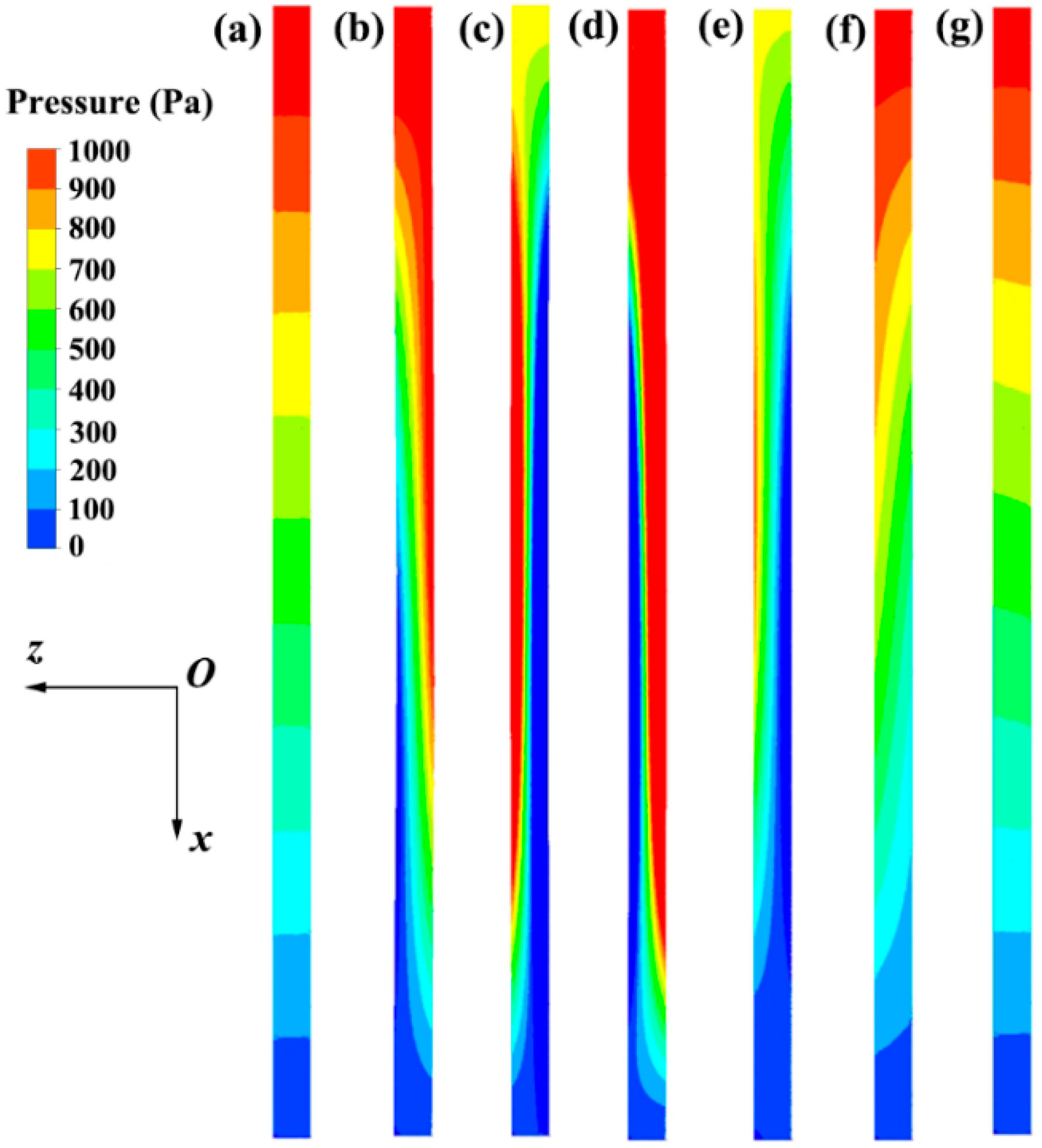
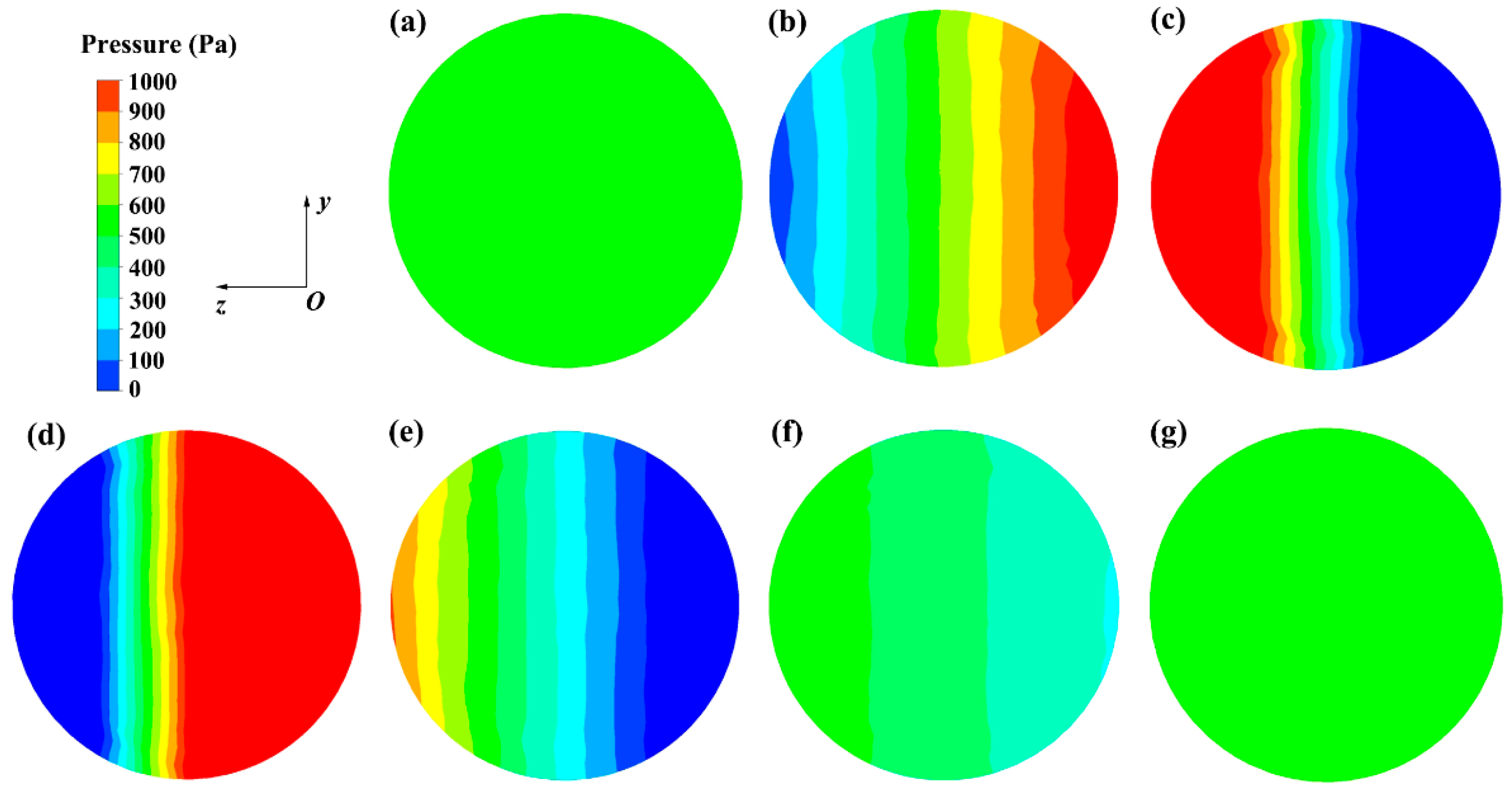
The contours of the pressure distribution of liquid hydrogen on the vertical plane (y = 0) are shown in Figure 10, and the pressure distribution contours on the cross-section plane (x = 1.5 m) are shown in Figure 11. Before the pipe is subjected to the external transient impact (i.e., t = 0 s), the pressure of liquid hydrogen decreases uniformly along the flow direction, with the pressure in the cross-sectional direction being nearly constant. After suffering from the external impact, the pipe is deformed and consequently works on the liquid hydrogen. From Figure 10 and Figure 11, it can be seen that partial energy induced by the external transient impact is converted into the pressure energy of liquid hydrogen. The pressure distribution of liquid hydrogen in the cross-section direction is no longer constant. Instead, liquid pressure increases along the deformation direction. For example, the pipe deforms in the -z direction at 0.01 s, and the liquid pressure increases along the same direction. As shown in Figure 9a, the deformation amplitude of the pipe decreases with time, and the pressure distribution characteristics of liquid hydrogen gradually return to the state before the external transient impact is applied. Though the external impact is transient, the pressure distribution is influenced for approximately 0.3 s.
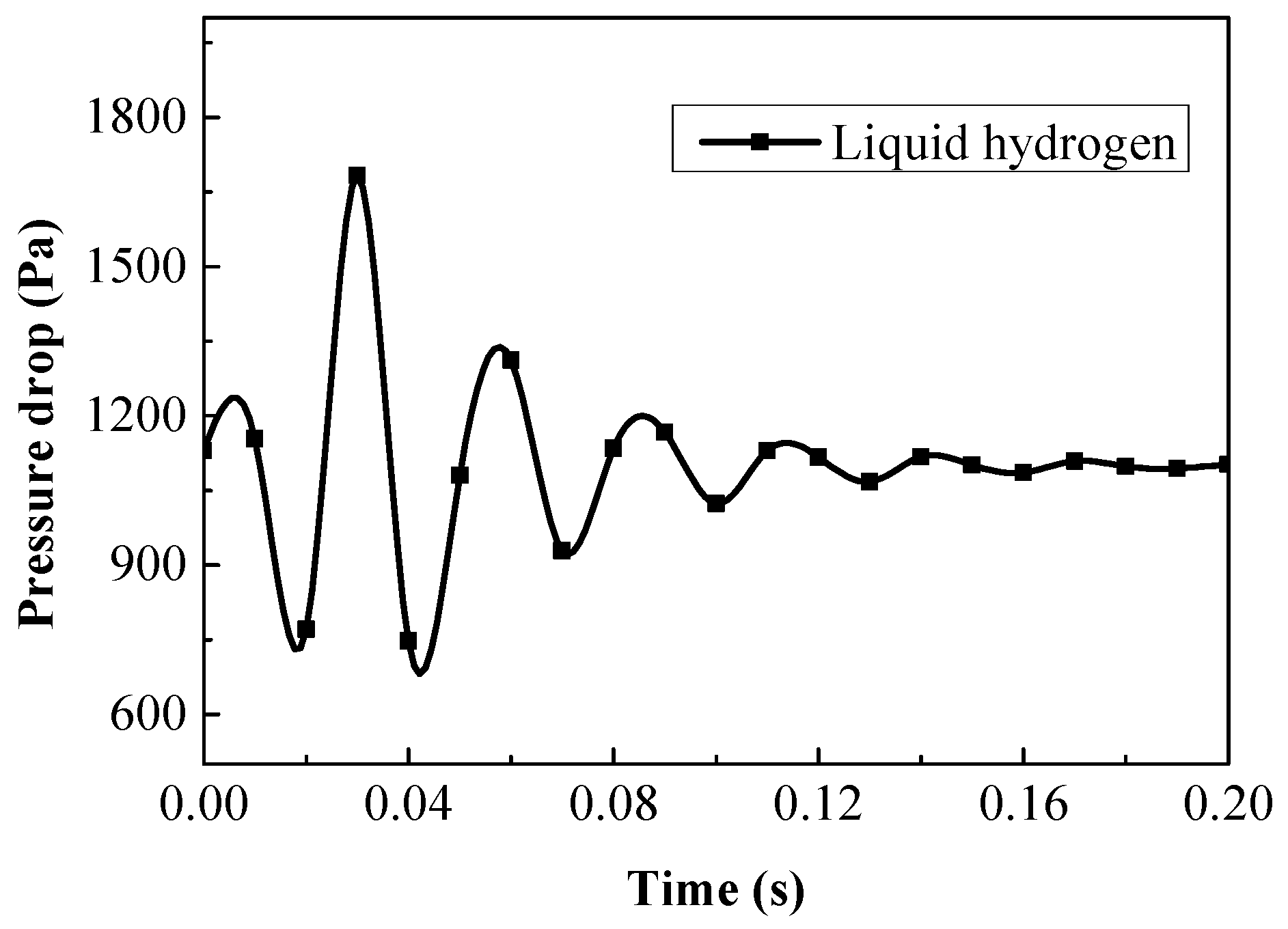
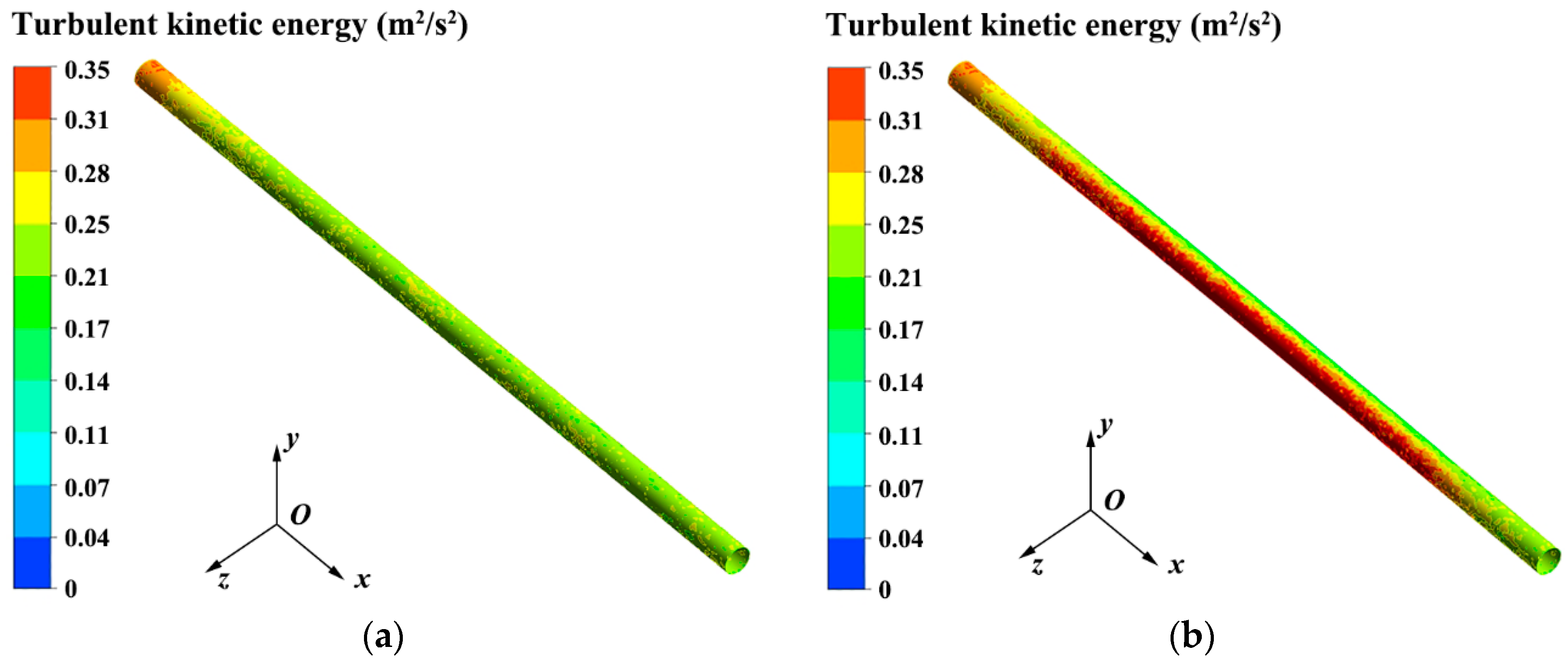
Variations in the pressure drop between the entrance and exit of the pipe with time are shown in Figure 12. When the pipe is subjected to the external transient impact, the pressure drop of liquid hydrogen in the pipe presents fluctuating characteristics. Figure 13 illustrates the turbulent kinetic energy contours near the pipe wall at the time of 0 and 0.01 s, respectively. It is apparent that the external transient impact enhances the disturbance of liquid hydrogen near the wall of the pipe. In addition, the changes in the flow cross-sectional area and flow direction increase the resistance of the liquid flow. On the other hand, the deformed pipe wall works on the fluid and increases the pressure energy of fluid. The increased flow resistance and the energy induced by the deformed pipe both affect the flow of liquid hydrogen, and contribute to the fluctuating characteristics of liquid pressure drop. In addition, the variation amplitude of the pressure drop gradually decreases with time and approaches the initial state.
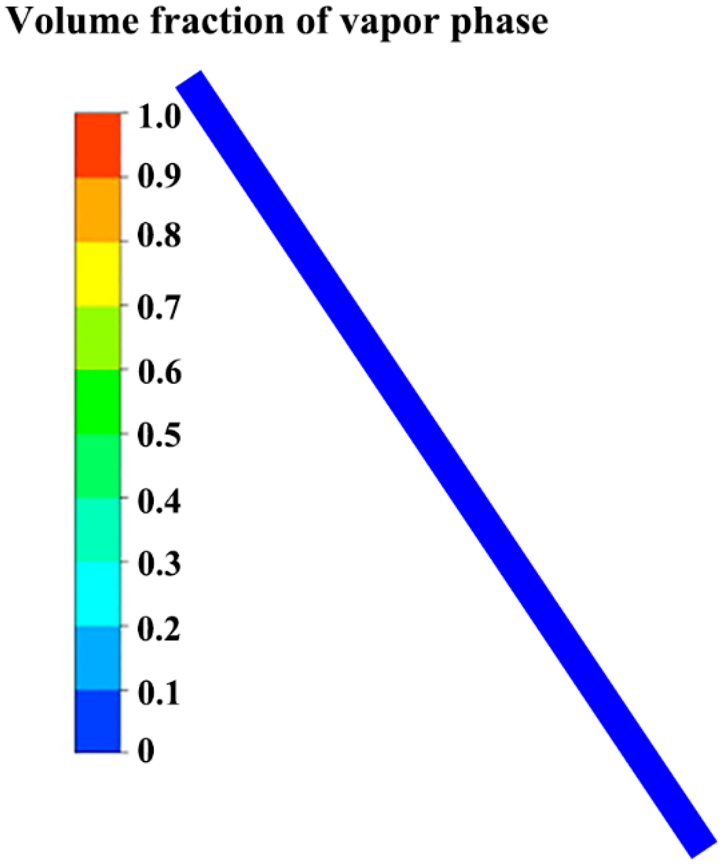
The phase state of liquid hydrogen in the pipe is also investigated. The volume fraction of vapor phase in the pipe remains 0 even after the external transient impact, as shown in Figure 14. It should be noted that liquid hydrogen is saturated at the exit and subcooled inside the pipe, and the wall is adiabatic. The result indicates that little energy of the external transient impact is transformed into the internal energy of liquid hydrogen. Instead, the energy is dissipated by the fixed support constraints at both ends of the pipe, and transformed into the pressure energy and kinetic energy of the fluid. However, if there is heat loss through the pipe wall, the strengthened liquid turbulence will enhance the heat transfer between liquid hydrogen and the wall [24], which could possibly induce two-phase flow in the pipe, threatening the safe operation of the liquid transportation system. Specifically, the vapor phase in the pipe could cause pressure oscillation and pipe vibration. A geyser may occur and lead to the failure of the pipe [36]. In addition, the normal workings of equipment in the transportation system (e.g., flowmeter and pump) are influenced.
In the present work, the pipe is not ruptured during the impact. It is apparent that the action region of the external transient impact suffers from the strongest stress intensity. Establishing a linearization path at the shortest distance along the wall thickness direction, the membrane strength is calculated to be 98.5 MPa and the membrane plus bending stress is calculated to be 433.2 MPa at the time of 0.01 s, which are within the designed stress intensity. The study predicts and reveals the flow characteristics of liquid hydrogen in a pipe suffering from external transient impact, which could provide theoretical guidance for formulating the emergency plan, identifying the potential accident by monitoring the fluid flow parameters, etc. and thus the safe operation of liquid hydrogen storage and transportation systems. In view of theoretical guidance for the safe handling of liquid hydrogen, mechanical analysis of the pipe under external transient impact, the flow of liquid hydrogen in a pipe under pipe rupture conditions, etc. need to be investigated further.
5. Conclusions
A three-dimensional CFD model predicting the flow of liquid hydrogen in a pipe is designed and validated, and the fluid–structure coupling calculation for the pipe under external transient impact is performed. The flow characteristics of liquid hydrogen in the pipe under external transient impact are then numerically analyzed. The main conclusions are as follows:
The mixture multiphase model and realizable k-ε model could be used to simulate the flow and heat transfer of liquid hydrogen in a pipe.
The pipe will deform and vibrate when suffering from external transient impact. The pipe vibration attenuates rapidly, and the positive amplitude attenuates to 6.9% of the maximum amplitude 0.2 s after the transient impact, while the amplitude of pipe vibration decreases slowly with time when no fluid exists in the pipe.
After suffering from the external impact, the pressure of liquid hydrogen in the cross-section plane increases along the pipe deformation direction, and the pressure distribution is influenced for approximately 0.3 s though the external impact is transient. External transient impact enhances the disturbance of liquid hydrogen near the wall of the pipe. The increased flow resistance and the energy induced by the deformed pipe both affect the flow of liquid hydrogen, and contribute to the fluctuating characteristics of the liquid pressure drop. In addition, the phase state of liquid hydrogen remains unchanged in the pipe, i.e., the volume fraction of vapor phase in the pipe remains 0, indicating that little energy of the external transient impact is transformed into the internal energy of liquid hydrogen.
Author Contributions
Conceptualization, Y.L. and Y.Q.; methodology, Y.L. and Z.L.; software, Y.L.; validation, Y.L.; formal analysis, Y.L. and G.L.; investigation, Y.L.; data curation, Y.L.; writing—original draft preparation, Y.L.; writing—review and editing, Y.L. and Y.Q.; supervision, Y.L.; funding acquisition, Y.L. and Y.Q. All authors have read and agreed to the published version of the manuscript.
Funding
This research was funded by the State Key Laboratory of Technologies in Space Cryogenic Propellants, grant number SKLTSCP202006.
Institutional Review Board Statement
Not applicable.
Informed Consent Statement
Not applicable.
Data Availability Statement
Not applicable.
Conflicts of Interest
The authors declare no conflict of interest.
References
- Christopher, W.; Thomas, K.; Boris, B.; Krewer, U.; Rauschenbach, R. Modelling and designing cryogenic hydrogen tanks for future aircraft applications. Energies 2018, 11, 105. [Google Scholar]
- Aziz, M. Liquid Hydrogen: A review on liquefaction, storage, transportation, and safety. Energies 2021, 14, 5917. [Google Scholar] [CrossRef]
- Chen, J.; Gao, X.; Shao, S.; Hu, H.; Xie, J.; Li, N.; Gao, N. Numerical investigation of the vortex tube performance in novel precooling methods in the hydrogen fueling station. Int. J. Hydrogen Energy 2021, 46, 5548–5555. [Google Scholar] [CrossRef]
- Bethoux, O. Hydrogen fuel cell road vehicles and their infrastructure: An option towards an environmentally friendly energy transition. Energies 2020, 13, 6132. [Google Scholar] [CrossRef]
- Sakamoto, J.; Sato, R.; Nakayama, J.; Kasai, N.; Shibutani, T.; Miyake, A. Leakage-type-based analysis of accidents involving hydrogen fueling stations in Japan and USA. Int. J. Hydrogen Energy 2016, 41, 21564–21570. [Google Scholar] [CrossRef] [Green Version]
- Witcofski, R.D.; Chirivella, J.E. Experimental and analytical analyses of the mechanisms governing the dispersion of flammable clouds formed by liquid hydrogen spills. Int. J. Hydrogen Energy 1984, 9, 425–435. [Google Scholar] [CrossRef]
- Marinescu-Pasoi, L.; Sturm, B. Messung der Ausbreitung einer Wasserstoff- und Propangaswolke in Bebauten Gelande und Gasspezifische Ausbreitungversuche; Reports R-68.202 and R-68.264; Battelle Ingenieurtechnik GmbH: Eschborn, Germany, 1994. [Google Scholar]
- Hooker, P.; Willoughby, D.B.; Royle, M. Experimental releases of liquid hydrogen. In Proceedings of the 4th International Conference on Hydrogen Safety, San Francisco, CA, USA, 12–14 September 2011. [Google Scholar]
- Verfondern, K.; Dienhart, B. Experimental and theoretical investigation of liquid hydrogen pool spreading and vaporization. Int. J. Hydrogen Energy 1997, 22, 649–660. [Google Scholar] [CrossRef]
- Verfondern, K.; Dienhart, B. Pool spreading and vaporization of liquid hydrogen. Int. J. Hydrogen Energy 2007, 32, 2106–2117. [Google Scholar] [CrossRef]
- Sklavounos, S.; Rigas, F. Fuel gas dispersion under cryogenic release conditions. Energy Fuels 2005, 19, 2535–2544. [Google Scholar] [CrossRef]
- Hansen, O.R. Liquid hydrogen releases show dense gas behavior. Int. J. Hydrogen Energy 2020, 45, 1343–1358. [Google Scholar] [CrossRef]
- Ichard, M.; Hansen, O.R.; Middha, P.; Willoughby, D. CFD computations of liquid hydrogen releases. Int. J. Hydrogen Energy 2012, 37, 17380–17389. [Google Scholar] [CrossRef]
- Venetsanos, A.G.; Bartzis, J.G. CFD modeling of large-scale LH2 spills in open environment. Int. J. Hydrogen Energy 2007, 1, 2171–2177. [Google Scholar] [CrossRef]
- Pu, L.; Shao, X.; Zhang, S.; Lei, G.; Li, Y. Plume dispersion behaviour and hazard identification for large quantities of liquid hydrogen leakage. Asia-Pac. J. Chem. Eng. 2019, 14, e2299. [Google Scholar] [CrossRef]
- Shao, X.; Pu, L.; Tang, X.; Yang, S.; Lei, G.; Li, Y. Parametric influence study of cryogenic hydrogen dispersion on theoretical aspect. Int. J. Hydrogen Energy 2020, 45, 20153–20162. [Google Scholar] [CrossRef]
- Liu, Y.; Wei, J.; Lei, G.; Chen, H.; Lan, Y.; Gao, X.; Wang, T.; Jin, T. Spread of hydrogen vapor cloud during continuous liquid hydrogen spills. Cryogenics 2019, 103, 102975. [Google Scholar] [CrossRef]
- Jin, T.; Liu, Y.; Wei, J.; Zhang, D.; Wang, X.; Lei, G.; Wang, T.; Lan, Y.; Chen, H. Numerical investigation on the dispersion of hydrogen vapor cloud with atmospheric inversion layer. Int. J. Hydrogen Energy 2019, 44, 23513–23521. [Google Scholar] [CrossRef]
- Liu, Y.; Liu, Z.; Wei, J.; Lan, Y.; Yang, S.; Jin, T. Evaluation and prediction of the safe distance in liquid hydrogen spill accident. Process Saf. Environ. Prot. 2021, 146, 1–8. [Google Scholar] [CrossRef]
- Giannissi, S.G.; Venetsanos, A.G.; Markatos, N.; Bartzis, J.G. CFD modeling of hydrogen dispersion under cryogenic release conditions. Int. J. Hydrogen Energy 2014, 39, 15851–15863. [Google Scholar] [CrossRef]
- Giannissi, S.G.; Venetsanos, A.G. Study of key parameters in modeling liquid hydrogen release and dispersion in open environment. Int. J. Hydrogen Energy 2018, 43, 455–467. [Google Scholar] [CrossRef]
- Liu, W.; Yang, Z.; Zhang, B.; Lv, P. Experimental study on the effects of mechanical vibration on the heat transfer characteristics of tubular laminar flow. Int. J. Heat Mass Transf. 2017, 115, 169–179. [Google Scholar] [CrossRef]
- Tian, S.; Barigou, M. An improved vibration technique for enhancing temperature uniformity and heat transfer in viscous fluid flow. Chem. Eng. Sci. 2015, 123, 609–619. [Google Scholar] [CrossRef] [Green Version]
- Zheng, Y.; Chen, J.; Shang, Y.; Chang, H.; Chen, H.; Shu, S. Numerical analysis of the influence of wall vibration on heat transfer with liquid hydrogen boiling flow in a horizontal tube. Int. J. Hydrogen Energy 2017, 42, 30804–30812. [Google Scholar] [CrossRef]
- Chen, H.; Zheng, Y.; Chang, H.; Chen, J.; Shang, Y.; Shu, S. Numerical simulation of liquid hydrogen two-phase flow in horizontal vibrating tube. Cryog. Supercond. 2018, 46, 8–12. (In Chinese) [Google Scholar]
- Lemmon, E.W.; Huber, M.L.; Mclinden, M.O. NIST Standard Reference Database 23: Reference Fluid Thermodynamic and Transport Properties-REFPROP, Version 9.1; National Institute of Standards and Technology, Standard Reference Data Program: Gaithersburg, MD, USA, 2013. [Google Scholar]
- Mikko, M.; Veikko, T.; Sirpa, K. On the Mixture Model for Multiphase Flow; Technical Research Center of Finland, VTT Publications: Espoo, Finland, 1996. [Google Scholar]
- Lee, W.H. A Pressure Iteration Scheme for Two-Phase Flow Modeling; Los Alamos National Laboratory: Los Alamos, NM, USA, 1979; LA-UR-79-975. [Google Scholar]
- Shih, T.H.; Liou, W.W.; Shabir, A.; Zhu, J. A new eddy viscosity model for high Reynolds number turbulent flows: Model development and validation. Comput. Fluids 1995, 24, 227–238. [Google Scholar] [CrossRef]
- Tatsumoto, H.; Shirai, Y.; Shiotsu, M.; Hata, K.; Naruo, Y.; Kobayashi, H.; Inatani, Y.; Kinoshita, K. Forced convection heat transfer of subcooled liquid hydrogen in horizontal tubes. AIP Conf. Proc. 2012, 1434, 747–754. [Google Scholar]
- Wu, W.B.; Wang, Y.L.; Shao, T.H.; Fu, Z.C. Cryogenic Material, 1st ed.; China Machine Press: Beijing, China, 1988; p. 143. [Google Scholar]
- ANSYS. ANSYS 14.5 Help; ANSYS, Inc.: Canonsburg, PA, USA, 2011. [Google Scholar]
- Lalanne, C. Shock analysis. In Mechanical Vibration and Shock Analysis—Volume 2: Mechanical Shock, 2nd ed.; ISTE Ltd.: London, UK, 2009. [Google Scholar]
- Ye, S.Q.; Chen, H.K.; Tang, H.M. The calculation method for the impact force of the rockfall. China Railw. Sci. 2010, 31, 56–62. (In Chinese) [Google Scholar]
- Deng, B.C.; Yang, S.Q.; Xie, X.J.; Wang, Y.L.; Pan, W.; Li, Q.; Gong, L.H. Thermal performance assessment of cryogenic transfer line with support and multilayer insulation for cryogenic fluid. Appl. Energy 2019, 250, 895–903. [Google Scholar] [CrossRef]
- Mao, H.; Li, Y.; Huang, X.; Xia, S.; Sundén, B. Investigation on the elimination of geyser in a cryogenic pipe by a recirculation method. Appl. Therm. Eng. 2021, 197, 117428. [Google Scholar] [CrossRef]
Figure 1.
Illustration of the calculation domain of liquid hydrogen flow in horizontal pipe [30].
Figure 1.
Illustration of the calculation domain of liquid hydrogen flow in horizontal pipe [30].

Figure 2.
Comparison between the simulation results and the experimental data.

Figure 3.
Physical model for the fluid–structure coupling.

Figure 4.
Illustration of the external transient impact.

Figure 5.
Computational mesh for the solid domain: (a) mesh in the entrance plane; (b) mesh near the impact region.
Figure 5.
Computational mesh for the solid domain: (a) mesh in the entrance plane; (b) mesh near the impact region.

Figure 6.
Computational mesh for the fluid domain.

Figure 7.
Mesh independency analysis: (a) vertical deformation of the impact point along -z direction at 0.01 s; (b) pressure drop between the entrance and exit of the pipe at 0.01 s.
Figure 7.
Mesh independency analysis: (a) vertical deformation of the impact point along -z direction at 0.01 s; (b) pressure drop between the entrance and exit of the pipe at 0.01 s.

Figure 8.
Pipe total deformation at 0.01 s with liquid hydrogen inside the pipe.

Figure 9.
Vertical deformation of the impact point in z direction: (a) with liquid hydrogen in the pipe; (b) without fluid in the pipe.
Figure 9.
Vertical deformation of the impact point in z direction: (a) with liquid hydrogen in the pipe; (b) without fluid in the pipe.

Figure 10.
Contours of the pressure distribution of liquid hydrogen on the plane of y = 0 (a–g corresponding to the time of 0, 0.01 s, 0.02 s, 0.03 s, 0.04 s, 0.2 s and 0.3 s, respectively).
Figure 10.
Contours of the pressure distribution of liquid hydrogen on the plane of y = 0 (a–g corresponding to the time of 0, 0.01 s, 0.02 s, 0.03 s, 0.04 s, 0.2 s and 0.3 s, respectively).

Figure 11.
Contours of the pressure distribution of liquid hydrogen on the cross-section plane of x = 1.5 m (a–g corresponding to the time of 0, 0.01 s, 0.02 s, 0.03 s, 0.04 s, 0.2 s and 0.3 s, respectively).
Figure 11.
Contours of the pressure distribution of liquid hydrogen on the cross-section plane of x = 1.5 m (a–g corresponding to the time of 0, 0.01 s, 0.02 s, 0.03 s, 0.04 s, 0.2 s and 0.3 s, respectively).

Figure 12.
Variations in the pressure drop between the entrance and exit of the pipe with time.

Figure 13.
Turbulent kinetic energy contours near the pipe wall: (a) t = 0 s; (b) t = 0.01 s.

Figure 14.
Volume fraction of vapor phase in the pipe after the external transient impact.

Publisher’s Note: MDPI stays neutral with regard to jurisdictional claims in published maps and institutional affiliations. |
© 2022 by the authors. Licensee MDPI, Basel, Switzerland. This article is an open access article distributed under the terms and conditions of the Creative Commons Attribution (CC BY) license (https://creativecommons.org/licenses/by/4.0/).
Share and Cite
MDPI and ACS Style
Liu, Y.; Qiu, Y.; Liu, Z.; Lei, G. Modeling and Analysis of the Flow Characteristics of Liquid Hydrogen in a Pipe Suffering from External Transient Impact. Energies 2022, 15, 4154. https://0-doi-org.brum.beds.ac.uk/10.3390/en15114154
AMA Style
Liu Y, Qiu Y, Liu Z, Lei G. Modeling and Analysis of the Flow Characteristics of Liquid Hydrogen in a Pipe Suffering from External Transient Impact. Energies. 2022; 15(11):4154. https://0-doi-org.brum.beds.ac.uk/10.3390/en15114154
Chicago/Turabian StyleLiu, Yuanliang, Yinan Qiu, Zhan Liu, and Gang Lei. 2022. "Modeling and Analysis of the Flow Characteristics of Liquid Hydrogen in a Pipe Suffering from External Transient Impact" Energies 15, no. 11: 4154. https://0-doi-org.brum.beds.ac.uk/10.3390/en15114154
Note that from the first issue of 2016, this journal uses article numbers instead of page numbers. See further details here.