Article

Steam Temperature Characteristics in Boiler Water Wall Tubes Based on Furnace CFD and Hydrodynamic Coupling Model

1
Research Institute of Boiler, Harbin Boiler Company Limited, Harbin 150001, China
2
School of Energy Science and Engineering, Harbin Institute of Technology, Harbin 150001, China
3
Institute of Thermal Science and Technology, Shandong University, Jinan 250061, China
*
Authors to whom correspondence should be addressed.
Submission received: 9 May 2022 / Revised: 18 June 2022 / Accepted: 23 June 2022 / Published: 28 June 2022
(This article belongs to the Special Issue Modelling of Thermal and Energy Systems)

Abstract

:
With the development of power plant units of higher capacity and with improved parameters, the proportion of high-capacity units for generating power has increased; this requires large capacity units to take responsibility for power-grid peak shaving. When the boiler operates at low loads, the working fluid in the boiler water wall tubes is subjected to high heat flux in the furnace, which can cause heat transfer deterioration, tube overheating or even leakage. Therefore, it is particularly important to study the reliability of the boiler hydrodynamic cycle during peak shaving (low load operation). This study takes a 1000 MW ultra-supercritical single-reheat Π type boiler with single furnace and double tangential firing as the research object. A furnace Computational Fluid Dynamics (CFD) and hydrodynamic coupling analysis model is established and verified according to the actual operating conditions on site. The calculation results show that the simulated value is in good agreement with the actual operating value. Therefore, the model established in this study can reflect the real situation of the on-site furnace to a certain extent, and has high reliability. Based on the fitting results, the causes of steam temperature deviation of the boiler water wall are analyzed, and measures to reduce the deviation are proposed to provide a necessary basis for power plant operation and boiler design.

1. Introduction

Hydrodynamic calculation is one of the key technologies in the design of large-scale utility boilers, which is significant in ensuring the safe and reliable operation of boilers. As the evaporation end point of a once-through boiler is not fixed, the adjustment of heat absorption share of the water wall is very important. The excessive heat absorption share of the water wall may cause an elevated outlet temperature, which may result in excessively high temperature and increase the deviation of the water wall of the upper furnace, and may also cause difficulties in the design of the separator. In contrast, the insufficient heat absorption of the water wall may lead to the existence of vapor-liquid two-phase medium at super heater inlet, resulting in uneven distribution [1,2,3,4,5]. For a vertical tube water wall, under the condition of meeting the minimum degree of superheat for minimum once-through load, the lower the outlet temperature of the water wall is, the better it is for reduction of wall temperature and temperature difference of water wall tubes. The working pressure of the furnace water wall decreases with the reduction of load, which reduces the sub-cooling degree of working fluid at the water wall inlet. Therefore, for once-through boilers operating with variable pressure, excessive enthalpy of the working fluid at the water wall inlet at low loads can easily lead to working fluid dry out and excessive medium temperature at outlet as well as instability in the medium flow. Therefore, establishing the hydrodynamic calculation model for the boiler water wall based on the boiler situation and operational conditions is necessary [6,7].
The process of boiler hydrodynamic calculation for a once-through complex using manual calculation mostly adopts the graphical or trial-and-error method. Its solving process involves cumbersome variables, charts, formulas, complex logic, and massive iterative calculation. The manual calculation method wastes time and laboratory resources, with insufficient accuracy and sometimes fallibility. Manual calculation is particularly inadequate for modern high-capacity boilers where the steam-water circuit is once-through complex. Therefore, it is necessary to develop a boiler software platform with auxiliary design function to help designers complete the design work more conveniently, accurately and optimally on a computer [3,8,9,10,11,12,13,14].
At present, many scholars worldwide have conducted extensive theoretical and experimental research on the heat transfer and hydrodynamic characteristics of the boiler water wall of (ultra) supercritical parameter units. Applying the calculation theory of fluid pipe networks, Bi Yanshuang et al. [15] studied the heat transfer and hydrodynamic model of the spiral water wall of the once-through boiler and obtained the flow pressure drop, flow distribution, and wall temperature characteristics of the water wall at different loads [15]. Yang Chen and Wang Pu [16,17] studied the water wall characteristics of down-shot firing boilers with supercritical pressure through numerical simulation and real furnace tests, and obtained the temperature field, flow field distribution, and heat transfer characteristics of the down-shot firing boiler water wall. Wang Weishu and Zhu Xiaojing [18,19] studied the flow and heat transfer characteristics of the vertical tube water wall of an ultra-supercritical pressure boiler through operational load and under low-flow conditions. Zhu Ming et al. [20] reasonably simplified the combustion and hydrodynamic process in a large capacity ultra-supercritical pressure tower boiler, and established a discrete mathematical and physical model to obtain the heat transfer parameters in the furnace and wall temperature distribution of the water wall under typical working conditions. Wang, Pan and Guo Yumeng [21,22] conducted experimental research on the heat transfer characteristics of vertical bare tubes and vertical internally threaded tubes with ultra-supercritical pressure, and obtained a mass of basic data. Tucakovic et al. [23] proposed a thermo-hydraulic analysis method for both DC and drum boilers, and calculated and analyzed the water circulation safety of a 350 MW drum boiler under different loads. Their findings showed that the internal threaded tube scheme had a greater safety margin than the light tube scheme. Park et al. [24] numerically simulated the thermal characteristics of an 800 MW supercritical DIRECT current boiler by using a 3D furnace combustion model and a 1D flow and heat transfer model of ‘soda water’ and their calculated results were in good agreement with the data of the power plant. Kim and Choi [12] established a model of drum water level and flow distribution for a natural circulating boiler water circulation system consisting of drum, descending pipe and ascending pipe. According to the basic design parameters of the boiler, the model can calculate the water circulation characteristics when the load changes or fuel quantity changes.
Most of the aforementioned hydrodynamic calculation models or programs are based on a specific boiler type, or are only suitable for relatively simple water circulation systems, or are carried out by simulating the manual hydrodynamic calculation method, which has poor universality and extensibility. Therefore, developing a commonly-used boiler hydrodynamic calculation software is an important task [2,25].
The hydrodynamic calculation program developed in this study is suitable for calculating and analyzing the hydrodynamic characteristics and wall temperature characteristics of ultra (supercritical) boilers and drum boilers with various capacity grades, various steam parameters, various furnace types and combustion technologies. It can calculate the flow distribution of the water wall circuit, change of pressure along the flow process, distribution of outlet steam temperature, changing trends of working fluid temperature and tube wall temperature vertically at all loads, and check the wall temperature safety characteristics of water wall at various loads to provide basic data for boiler design and operation. The calculation process of boiler hydrodynamics is shown in Figure 1.
The output of the program includes friction resistance of each circuit, local resistance, gravity pressure drop, single tube flow and mass flow rate as well as pressure distribution of each node. Then, the wall temperature calculation module permits the calculation of the inner and outer wall temperatures of each circuit and tube section. A summary of the discussion of the above models shows that the common point is to determine the wall temperature through hydrodynamic calculation, and the wall temperature is an important index to measure during the site performance test [9]. The distribution of heat absorption directly determines the validity of the hydrodynamic calculation and working reliability of the heating surface. It should be as close as possible to the actual heat absorption [5,26,27]. Therefore, this study uses the self-developed furnace CFD and hydrodynamic coupling analysis model, combined with the actual operation data to correct the heat flux in order to provide guidance for subsequent projects or retrofit projects.

2. Details of 1000 MW Ultra Supercritical Boiler System

2.1. Boiler Overall Technical Proposal

The boiler shown in Figure 2 is an ultra-supercritical pressure once-through boiler operating with a sliding pressure, which adopts П Type arrangement, single furnace, single reheat, low NOx main burners with upper burnout air and staged combustion technology, reverse double tangential firing. The furnace has a membrane water wall with inner-threaded tubes, and a start-up system without a circulation pump. In addition to the coal/water ratio, the temperature control methods also include flue gas distribution baffles, burner tilt, spray water, and others. The boiler adopts a balanced draft, solid slag discharge, all steel frame, and all suspended structure. Shenhua coal is used in the design. The main original design parameters are presented in Table 1.

2.2. System

The furnace water wall adopts welded membraned walls with inner-threaded tubes that spirally rise upward. The furnace sectional size is 32,084 mm × 15,670 mm. There are a total of 2144 water wall tubes, of which 720 are for each of the front and rear walls and 352 are for both sidewalls. All tubes adopt 28.6 mm outer diameter, 5.8 mm THK (thickness), four-lead inner ribbed, 15 CrMoG material with 44.5 mm pitches. Flat steels welded between tubes are made up of 15CrMo material with 15.9 mm width and 6 mm thickness. A circle of intermediate transition header is installed between the upper and lower water walls to eliminate the heat absorption deviation as well as the temperature deviation of the lower furnace.
The boundary point between the water wall and superheater systems is the steam-water separator. All components between the inlet pipes of the water wall lower header to the outlet pipes of the water storage tanks belong to the water wall system. The working fluid at the outlet of the economizer is sent to two water wall inlet collecting headers through two large-diameter water supply pipes, and then sent to each lower header of the water wall with many distributing pipes before it goes through the front, rear, and two side water walls of the lower furnace and enters the middle mixing header for mixing to eliminate the heat absorption deviation. Then, the mixed water enters the front, rear, and two side walls of the upper furnace. The working fluid from the upper header of the front wall and the upper header of the two side walls is led to the roof tube inlet header, which goes through the roof tubes and then enters the outlet header outside the rear gas pass. The working fluid entering the rear water wall of the upper furnace goes through the furnace nose and the vestibule slope, and then enters the rear water wall outlet header. Then, the fluid is sent to the rear water wall hanger tubes and the two vestibule side walls through the two collecting headers. The working fluid from the rear water wall hanger tube outlet header and the two vestibule side walls is also sent to the roof tube outlet header. Two large-diameter connecting pipes send the working fluid to the rear gas pass manifold. Most of the working fluid is sent to the front, rear, and two side enclosure walls as well as the dividing wall through the connecting pipes. All working fluid from the enclosure upper header is introduced into the rear enclosure wall outlet header through connecting pipes, and then led to the two steam water separators arranged at the rear of the boiler through connecting pipes. The steam from the top of the separator is sent to the inlet header of the primary super heater and enters the superheating system. During startup, when the boiler operates under wet condition in recycling mode, after the two-phase medium from the water wall is separated in the steam water separator, the steam is led out from the upper part of the separator, and the separated water is sent to the storage tank from the bottom of the separator through connecting pipes. Then, a large-diameter drain pipe is used to send the recycled water to the water supply pipe upstream of the economizer by the startup circulating pump for mixing. Then, the water is sent to the economizer and water wall system to achieve the recycling operation. After the boiler reaches the minimum once-through load at the end of the start-up stage, because the start-up pump has been cut off, the start-up system enters dry operation mode. At this time, the steam-water separator only plays the role of steam collecting header and the medium in it is all steam.
The working fluid from the water wall upper outlet goes through roof tubes and then enters the roof outlet header. At this stage, 480 front roof tubes change into 240 tubes at the rear part through Y-shaped connectors. The entire roof adopts membrane tube walls.
The medium at the outlets of both vestibule side walls and rear water wall hanger tubes, which act as respective circuit, is introduced into the roof outlet header through connecting pipes. In this way, all working fluids from the furnace water wall outlet are collected in the roof outlet header, leaving which the fluid is introduced by connecting pipes into the front, rear, and side enclosure walls as well as the division wall of the boiler rear. Then, all enclosure wall outlet fluids enter the rear enclosure wall outlet header before entering the steam-water separator, which is arranged at the upper boiler through four large-diameter connecting pipes (457 mm × 70 mm).
All enclosure walls adopt membrane tube walls. The thickness of flat steel between tubes is 6 mm and that of division walls is 8 mm. All flat steels adopt 15CrMo material. All enclosure walls adopt upward flows, which are beneficial to prevent hydrodynamic instability at low loads or during startup.
The water wall lower header has a small diameter of 219 mm OD. The throttling orifice rings are moved to the inlet section of water wall tubes outside the water wall header. The inlet short tubes are 44.5 mm OD, and 6 mm THK, which is thicker. Throttling orifice rings are welded in the short tubes of throttling orifice rings, which are then connected to water wall tubes with 28.6 mm OD twice through Y-shaped connectors. The construction allows a larger throttling range that provides sufficient throttling capability. Flow rates in each water wall circuit are adjusted based on heat flux distribution horizontally and constructional characteristics to ensure even temperature in the water wall outlet fluid and prevent the occurrence of departure from nucleate boiling (DNB) and dry out (DRO) at certain circuit or tube sections subjected to dramatic heat flux or with complex constructions.

3. Thermal Load Distribution and Hydrodynamic Model

3.1. Working Condition of Water Cooled Wall

A 1000 MW ultra-supercritical pressure boiler is designed with both high flexibility and optimized economy, which determines the boiler operation with sliding pressure.
Due to the unfixed evaporation endpoint of the once-through boiler, the adjustment on water wall heat absorption ratio is very important. Excessive heat absorption ratio can bring elevated temperature at the water wall outlet, which may cause overheating at the upper furnace tubes as well as further deviation, and also brings difficulties for steam-water separator design. In contrast, insufficient heat absorption may result in two-phase fluids at the super heater inlet, which leads to the issue of uneven distribution.
For the vertical tube water wall, lower water wall outlet temperature is beneficial to reducing the tube wall temperature and temperature difference between tubes on conditions of satisfying the degree of superheat at minimum once-through load. Therefore, the increasing enthalpy of the water wall inlet fluid can easily bring evaporation and excessive temperature on the outlet fluid as well as instability in the flow of the working fluid. Table 2 shows the thermal parameters of the water wall in operation, and the load accounts for the working state of the water wall in the subcritical DC range.

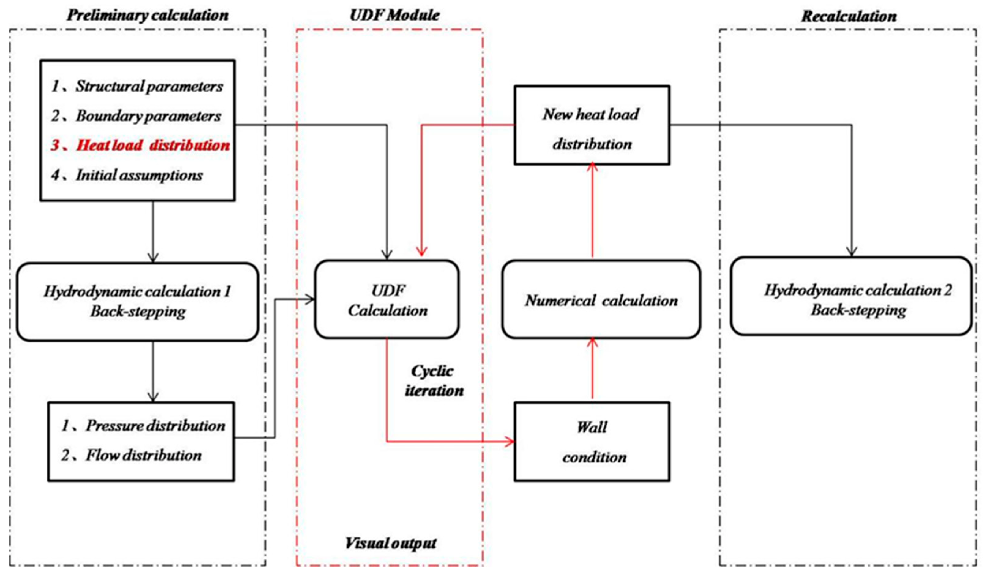
3.2. Development of the Furnace CFD and Hydrodynamic Coupling Analysis Model and Program

The core concept of this study is coupling, and the principle is the information interaction and iterative convergence process between the Hydro and Fluent modules. The Hydro module is responsible for calculating output working medium side information (loop pressure, flow, and temperature distribution) based on the supplied thermal load boundary. The Fluent module is responsible for calculating the output thermal load distribution based on the supplied working medium side boundary (translated into wall conditions). The result of coupling is the iterative convergence of water and fire side output information. The flow chart of this calculation method is shown in Figure 3.
The Fluent module mainly adopts 3D steady-state calculation and SIMPLE algorithm. The turbulence model uses a realizable two-way model and an LES model. Gas turbulent combustion is simulated by mixed fractional probability density function. Radiation heat transfer is calculated by the p-1 radiation model. A double matching rate model was used to simulate the volatilization of pulverized coal. For coke combustion, the power/diffusion control combustion model is adopted. The random track method is used to track pulverized coal particles. The post-treatment method was adopted for the generation of nitrogen oxides, mainly considering the generation effect of fuel nitrogen, thermal nitrogen, and rapid nitrogen. The specific simulation method is based on relevant literature [28,29,30,31]. For the simulation of fuel type NOx, the nitrogen in pulverized coal particles is evenly distributed in volatile matter and coke. Momentum equation, energy equation, K equation, ε equation, NO, and HCN transport equation are discretized by the second-order upwind scheme. In the processing of boundary conditions, the inlet of the burner is fixed speed inlet, and the method of golden wall function is used to deal with the transition calculation of the regional equation near the wall.
In the calculation of the ultra-supercritical boiler Hydro module, the calculation formula of working fluid resistance and heat transfer coefficient in water wall tube have to be obtained accurately. For the lifting project, the water wall not only has an internal thread pipe, but also has a light pipe. In addition, as the power generation companies generally propose the requirement of variable pressure operation for ultra-supercritical boilers, the water wall of the boiler not only needs to operate in the ultra-supercritical state under BMCR load condition, but also needs to work in the subcritical soda two-phase zone when the load is reduced. With the increase of pressure, the saturation temperature of water increases correspondingly, but the latent heat of vaporization decreases correspondingly, and the specific gravity difference between saturated water and saturated steam also decreases. At present, there are relatively accurate and mature calculation formulas [32]. As the light tube is in the low load area of the upper furnace, heat transfer deterioration generally does not occur. For the internally threaded pipe, we need to determine the ultra-supercritical pressure single-phase supercooled water and superheated steam resistance and heat transfer coefficient calculation formula, the critical region soda, two-phase resistance and calculation formula of normal working condition of the heat transfer coefficient of heat transfer, and two types of heat transfer deterioration in DNB and DRYOUT criterion and dry heat transfer coefficient formula (see Appendix A, Appendix B and Appendix C).
UDF, as a special tool for transmission between Fluent and Hydro, is relatively mature and easy to use. The entire UDF coupling route is shown in Figure 4. The UDF module is required to perform the complete hydrodynamic calculation and be able to interact and iterate with Fluent. However, if the complete route is adopted, a specific heat load distribution takes too long for each hydrodynamic calculation, such that achieving quick coupling with Fluent is difficult. A simplified hydrodynamic iterative calculation method is required. Therefore, the pressure and flow distributions are simplified in this study. The simplified route is shown in Figure 5. As the enthalpy is more sensitive to the temperature rather than pressure (i.e., the pressure has a slight effect on the heat transfer), the pressure along the height direction is assumed to be linearly distributed versus the height. The main influencing factor of the flow distribution is the structure and resistance distribution of the circuit, and the secondary influencing factor is the heat absorption of the circuit. For the same boiler, the circuit structure (i.e., the resistance distribution) is fixed, so the main factors are also fixed. In the actual operation, the water wall outlet temperature is fixed (i.e., the total heat absorption of the circuit is fixed and the heat absorption distribution along the height direction is unknown). Therefore, the flow can be regarded as fixed.

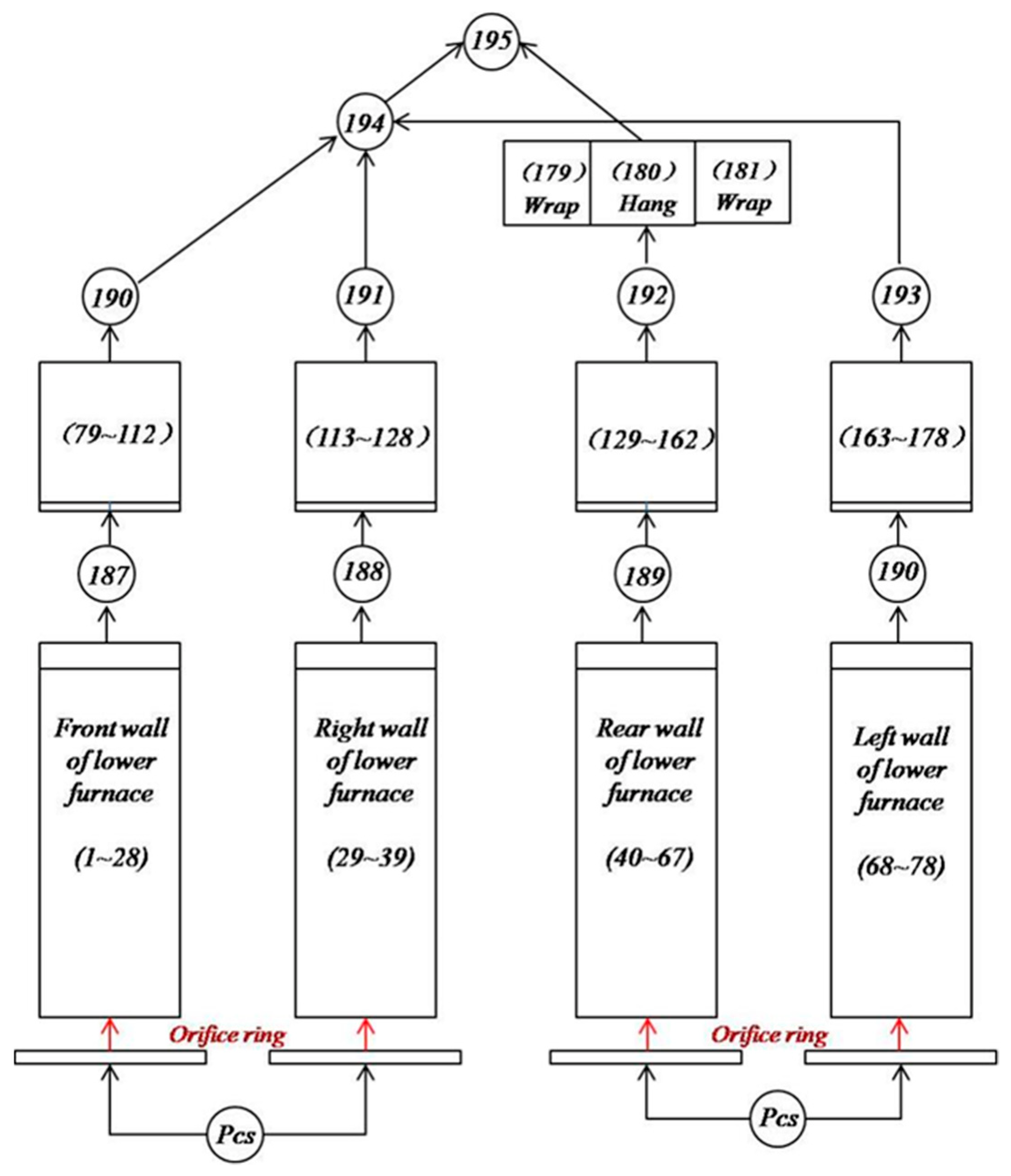
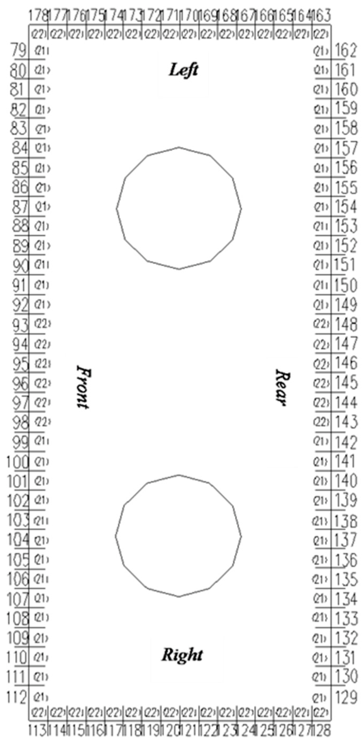
3.3. Grid and Loop of Hydrodynamic Flow System

To determine the flow rate in each circuit and the pressure distribution of the nodes, these unknowns shall be presumed in order to obtain the conservation equations of mass, momentum, and energy that the circuits, connecting pipes, and nodes comply with. By solving the closed nonlinear equation group composed of these equations, the flow distribution of each circuit and the pressure distribution of the nodes can be obtained. Figure 6 shows a schematic of the circuit and node division. The principle of dividing the calculation circuit of the water wall parallel tube panel is based on the characteristics of the heat load distribution curves along the furnace width and depth, and the circuits are more intensively distributed where the heat load changes rapidly, that is, the circuit is composed of fewer tubes. The circuits are sparser where heat load changes lightly, that is, the circuit is composed of additional tubes. In this way, the inhomogeneity of the heat load distribution can be fully reflected in the calculation, so that the arrangement of the throttling orifice rings has good control on the outlet steam temperature deviation.
To obtain the water wall flow distributions at each load, the lower furnace is divided into 78 circuits and the upper furnace is divided into 100 circuits. The circuit numbering starts from the front wall counterclockwise. For the lower furnace, circuits 1~28 are on the front wall, circuits 29~39 are on the right wall, circuits 40~67 are on the rear wall, and circuits 68~78 are on the left wall. For the upper furnace, circuits 79~112 are on the front wall, circuits 113~128 are on the right wall, circuits 129~162 are on the rear wall, and circuits 163~178 on the left wall.
The 3rd, 12th, 17th, 26th, 42nd, 51st, 56th, and 65th circuits of the lower furnace vertical tube water wall pass through the burners, and the throttling orifice rings in the same circuit have the same specifications. The schematic of the calculation circuit division of the lower furnace is shown in Figure 7, the schematic of the distribution of the water wall orifice rings on the four walls of the lower furnace is shown in Figure 8, and the schematic of the calculation circuit of the upper furnace, with circuit numbering and quantity of tubes, is shown in Figure 9.

3.4. Thermal Load Distribution Curve

Using extensive theoretical calculations and a large volume of real furnace test data, Mitsubishi Corporation of Japan proposed the complete distribution curve of the heat load along the height direction of the double tangential firing furnace and the heat absorption deviation law of the four walls. However, due to the influence of factors, such as the operation mode of the unit and the matching of auxiliary machines, the Mitsubishi thermal load design curve has deviated from the actual operating value. Therefore, the present study is based on the 1000 MW unit full-furnace 3D thermal state numerical simulation results to make corrections, and the furnace heat load distribution is finally obtained. The water wall heat load distribution diagram of the numerical simulation is shown in Figure 10. The specific correction method aims to calculate the new wall temperature distribution of the water cooling wall (including upper and lower water cooling walls) by numerical calculation according to the actual operation of the boiler. As the correction condition, the reverse derivation of the furnace heat load is carried out to obtain the boiler heat load distribution in accordance with the actual operation and hydrodynamic parameters under the boundary. Through the loading of coupled UDF, the thermal load is constantly corrected, and then the hydrodynamic calculation is performed to obtain the temperature distribution of the loop working medium, and the comparison is made with the actual wall temperature distribution on site. The standard of iteration calculation is that the temperature distribution of the loop working medium calculated by hydrodynamics is highly consistent with the actual wall temperature distribution on site.
According to the numerical calculation results, the heat load of each wall is processed into two dimensions. Based on the 2D results, the data in the area are averaged and processed in accordance with the corresponding area of the circuit and tube sections into the format accepted by the hydrodynamic calculation. The heat absorption deviation of the four walls is shown in Figure 11 and Figure 12.

4. Hydrodynamic Calculation Results

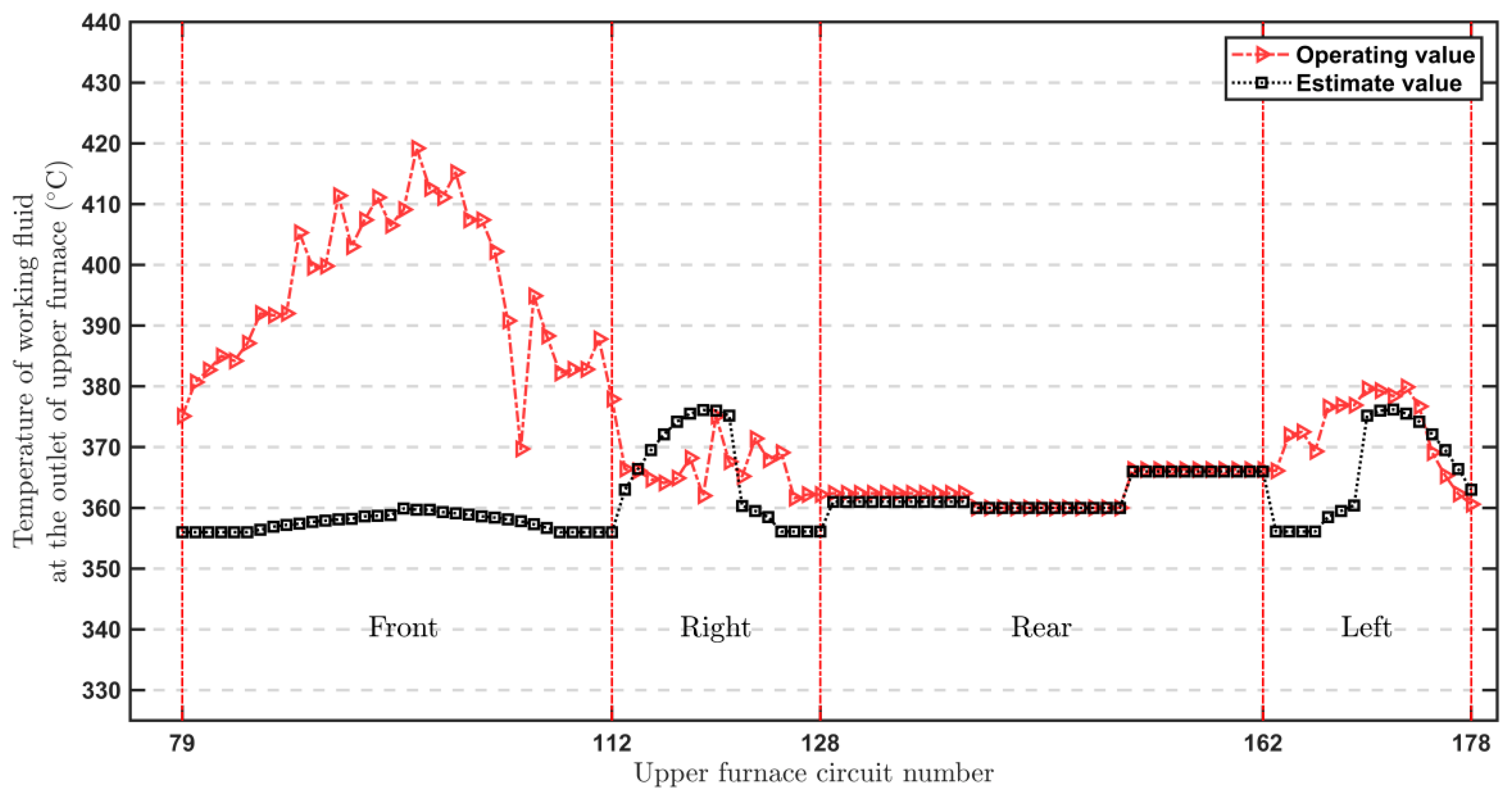
4.1. Comparison of Calculation and Field Operation Data

To analyze the causes of large deviations of boiler heat absorption, this study selected a group of operational data in the condition of a large deviation in steam temperature for fitting hydrodynamic calculation where the electric generating load was 517 MW. The data in Table 2 were taken as the hydrodynamic calculation boundary conditions. Figure 13 shows the comparison between the calculated working fluid temperature at the outlet of the upper furnace circuits by using traditional standards and the site operational value.
Figure 13 shows that the fluid temperature distribution working fluid at the upper front water wall outlet is relatively even according to the standard calculation method. The average temperature of the working fluid at the outlet of the upper front wall is 357.5 °C, the highest is 403.1 °C, the lowest is 381.2 °C, and the temperature difference is 3.9 °C. According to the site operational data, the average working fluid temperature at the outlet of upper front wall is 395.8 °C, the highest temperature is 419.2 °C, the lowest is 369.7 °C, and the temperature difference is 49.5 °C. The calculated values of the side and rear walls of the upper furnace are in good agreement with the site operational data. The main causes of the large difference in the temperature of the working fluid may be that the heat load distribution of the front wall calculated by theory is different from the actual heat-load distribution. Based on the current situation of peak load shaving, the boiler with the vertical tube water wall is extremely sensitive to the change of heat load (especially low load). The distribution of thermal deviation between high and low loads is dramatically different, so adopting the coupling calculation method to correct the heat load calculation is necessary to truly reflect the actual operation condition. The coupling result is shown in Figure 14.
Figure 14 shows that the numerical values calculated by coupling iteration are highly consistent with those in the actual site operation. Among them, the maximum temperature of the coupling calculation is 408.2 °C, the minimum temperature is 356 °C, the deviation of the two is 52.2 °C, and the average temperature is 371 °C. The maximum temperature of the site operational data is 419.2 °C, the minimum temperature is 360 °C, the deviation of the two is 59.2 °C, and the average temperature is 376 °C. The relative errors of maximum, minimum, and average values are respectively 2.62%, 1.11%, and 1.4%. In general, the coupled calculation values are in good agreement with the site operational data. Therefore, the hydrodynamic coupling calculation model established in this study and the selection of heat load have high reliability.

4.2. Analysis of Water Wall Coupling Calculation Results

The 15th circuit subjected to the strongest heat on the lower furnace front wall is selected for studying the wall temperature. Figure 15 shows the curves presenting variations of the working fluid temperature, inner wall temperature, middle wall temperature, outer wall temperature, and fin end temperature for the 15th circuit along the furnace height direction. At the operational load of 517 MW, the working fluid is sub cooled at the inlet and then the working fluid begins to evaporate and enters the two-phase region where the heat transfer coefficient increases considerably against the single-phase region. The working fluid temperature remains saturated. At 40 m level of the furnace, the working fluid is a superheated steam. The working fluid temperature at the lower furnace outlet is 422.4 °C. and the inner wall temperature is 468.1 °C. The intermediate point temperature is 475.7 °C. The outer wall temperature is 490 °C, and the fin end temperature is 498.8 °C.
For the upper furnace, the tubes subjected to the strongest heat on the front, rear, and side walls are studied. First, the 95th circuit on the front wall is studied. The curves presenting variations of the working fluid temperature, inner wall temperature, middle wall temperature, outer wall temperature. and fin end temperature for the 95th circuit along the furnace height direction of furnace are shown in Figure 16. At the site operation load of 517 MW, the working fluid temperature increases along the furnace height direction vertically. The maximum outer wall temperature of the upper furnace reaches 464 °C. The maximum temperature at the intermediate point is 451.7 °C, and the maximum temperature at the fin end is 459.1 °C.
Second, the 135th circuit subjected to the strongest heat on the rear wall is studied. Figure 17 shows the curves presenting variations of working fluid temperature, inner wall temperature, middle wall temperature, outer wall temperature, and fin end temperature of the 135th circuit along the furnace height direction. At the site operation load of 517 MW, the working fluid temperature increases as the height increases. When the height exceeds 8 m, the increase in the wall temperature slows down due to a reduction of the heat load. The maximum outer wall temperature of the upper furnace reaches 399.8 °C, the maximum temperature of the intermediate point is 381.5 °C, and the maximum temperature of the fin end is 398.6 °C.
Third, the 172nd circuit subjected to the strongest heat on the side wall is studied. Figure 18 shows the curves presenting variations of working fluid, inner wall, intermediate wall, outer wall, and fin end temperatures of the 172nd circuit on the left side of the upper furnace along the height direction. At the site operation load 517 MW, the working fluid at the outlet is superheated steam. When the height exceeds 8 m, the increase in wall temperature slows down due to the reduction of the heat load. The maximum outer wall temperature of the upper furnace reaches 400.7 °C, the maximum temperature of the intermediate point is 386.9 °C, and the maximum temperature of the fin end is 396.3 °C.
In general, at 517 MW load, the 15CrMoG material for boiler furnace water wall is a safe and reliable choice.

4.3. Cause Analysis of Steam Temperature Deviation of Water Wall and Measures to Reduce Deviation

When the boiler operates in dry state under low load, the working state of the water wall system is in the subcritical DC range. The working medium of the water wall system is steam water two-phase mixture, and the specific volume of the working medium on the steam water side changes greatly. Due to the superimposed factors, including the uneven heat load distribution in the furnace, large deviation on the flue gas side and reduced mass flow rate of the working medium, the thermal sensitivity of the water wall running in parallel is enhanced, and the steam temperature deviation of the water wall is increased. For the 1000 MW ultra supercritical boiler, the water wall structure has been determined. The main reasons for the deviation of the boiler water wall steam temperature are furnace heat load deviation and uneven flow distribution. The furnace heat load truly reflects the combustion condition in the furnace, and the boiler combustion is affected by factors such as air powder distribution deviation, secondary air volume deviation, operation coal quality deviation, and others. From the structural analysis of the water-cooled wall, the boiler is a rectangular furnace, the areas of the front and rear walls are larger than those of both side walls, and the rear wall water-cooled wall has no vertical section heating surface as large as the front wall. Because the largest area of the front wall is water-cooled and large differences in heat absorption of each part are superpositioned, the wall temperature deviation is greater than those of the two side walls and the rear wall.
If the outlet steam temperature deviation between the two adjacent tubes of the water wall and between the tubes along the furnace perimeter exceeds the allowable value, the water wall cracks, thereby affecting the safe and stable operation of the boiler. Therefore, our group recommends checking the cleanliness of the orifice ring and inlet header of the water wall tubes with a higher wall temperature, and adjusting the combustion operation control system and structural optimization to reduce the steam temperature deviation of the water wall.
The flue gas flow and temperature deviation at the furnace outlet can be reduced through combustion adjustment. The specific measures are as follows:
(1)
Conducting primary air leveling, reducing the deviation of pulverized coal concentration into the boiler at each corner of the burner by adjusting the shrinkage hole on the pulverized coal pipe, and ensuring the uniformity of pulverized coal at each corner of the burner.
(2)
Adjusting the air distribution of the burner and appropriately increasing the rigidity of the secondary air jet of the front wall.
(3)
By adjusting the swing angle of SOFA air, the tangential circle of the two flames is adjusted to the dispersed state to avoid excessive concentration of the heat load.
(4)
Standardizing the operation and combination mode of the coal pulverizer. When the carbon content of fly ash can be met, we can put the lower coal pulverizer into operation to control the enthalpy increase in the upper and lower furnaces.
(5)
When starting and stopping the pulverizer, the opening and closing time of the cold and hot air door is kept as long as possible to avoid the rapid change of the actual coal entering the furnace when the coal feeder is operated or switched, thereby reducing the large deviation of the coal water ratio during actual operation.
For the once-through boiler, there is no fixed dividing point between the evaporation heating surface and the superheater. Therefore, reasonably determining the superheat of the working medium at the outlet of water wall is important. Under the rated load, selecting the outlet temperature of the water wall mainly depends on the allowable service temperature of the built-in steam water separator material. For example, the steel of the separator is SA335-P12 and the water wall tube is 15CrMo, and both materials are lower than alloy steels. The allowable service temperature is 550 °C. A slightly lower outlet temperature of the water wall is also conducive to reducing the temperature deviation of the water wall.
When the boiler operates below 25% BMCR (i.e., it operates below the minimum DC load), we recommend that the power plant start the recirculation pump for wet operation to ensure the safe operation of the water wall. The start-up system with pump can improve the steam production of the boiler under low load, recover the heat and working medium during deep peak shaving and low load operation, and improve the temperature level of the working medium entering the water wall. During the start-up process and low load operation, the working medium flow in the boiler water wall tube is maintained at a level that is higher than the minimum flow. Because the water wall outlet is a steam water mixture with saturated temperature, the working medium and tube wall temperatures of each water wall tube along the furnace perimeter are uniform. The pump head can ensure the forward flow of the water wall system, which can reduce stagnation, backflow, and the possibility of hydrodynamic instability such as multiple values of hydrodynamic force, pulsation between pipes, overheating, and excessively high temperature of the water wall pipes. Therefore, the safety of the water wall system can be ensured.
According to the hydrodynamic calculation and field fitting calculation, under the operating condition of 517 MW load, the heat flux density of the front wall 16 circuit is relatively high and the steam temperature deviation of some adjacent pipelines is relatively large. However, the maximum wall temperature is still lower than the allowable maximum temperature of the existing pipes. If the expected effect of controlling the water wall temperature is still not achieved after checking the cleanliness of the throttle orifice and inlet header of the water wall pipe with high wall temperature, and after the aforementioned combustion operation adjustment and control system optimization, the diameter of the throttle orifice can be optimized and preliminarily evaluated. Adjusting the throttle orifice can improve the steam temperature deviation.

5. Conclusions

In this study, the hydrodynamic calculation of the 1000 MW ultra-supercritical primary reheat Π type single-furnace double tangential coal-fired boiler was carried out. The water wall was divided into a flow network system composed of flow circuit, pressure node, and connecting pipe. According to the mass conservation, momentum conservation, and energy conservation equations, a mathematical model for the calculation of the water wall flow and wall temperature of the boiler was established. The hydrodynamic simulation calculation of the water wall under field operation of 517 MW was conducted by directly solving the nonlinear flow balance and pressure drop balance equations.
The hydrodynamic simulation results of the water wall under the field operation condition of 517 MW were calculated. The relative errors of the maximum value, minimum value, and average value of the working medium temperature at the outlet of the upper furnace between the simulation calculation and the field operation data were 2.62%, 1.11%, and 1.4%, respectively. The simulated value was in good agreement with the field operation data. The simulated value can reflect the real situation of the field furnace type to a certain extent. The established hydrodynamic calculation model and heat load selection have high reliability.
The causes of water wall steam temperature deviation are analyzed on the basis of the hydrodynamic calculation results of the water wall of the boiler. Combined with our rich boiler design and operation experience, the measurements to reduce the water wall steam temperature deviation are proposed from three aspects: combustion operation adjustment, control system optimization, and structural optimization transformation. The front wall 16 circuit and some adjacent circuits with large steam temperature deviation are proposed to perform the optimization of the orifice diameter to improve the steam temperature deviation.

Author Contributions

X.G.: writing—original draft preparation, software; L.X.: writing—review and editing; G.Z.: writing—review and editing; G.W.: Investigation; Y.W.: Resources; Y.Y.: Data curation; J.G.: Funding acquisition; X.R.: Formal analysis. All authors have read and agreed to the published version of the manuscript.

Funding

This work has been financed by National Key R&D Program of China (2021YFC03001803-02).

Conflicts of Interest

No conflict of interest exists in the submission of this manuscript, and the manuscript is approved by all authors for publication.

Appendix A. Light Pipe Resistance and Heat Transfer Calculation

Appendix A.1. Single-Phase Supercooled Water and Superheated Steam

(1)
Friction pressure drop
The “Hydrodynamic Calculation Method of Power Plant Boiler” uses the following formula to calculate the frictional pressure drop of single-phase superheated water and superheated steam in the light pipe:
Δ P f = λ l d i ( ρ w ) 2 2 ρ
in the formula: Δ P f —friction pressure drop, Pa;
λ —coefficient of frictional resistance;
l —Tube length, m;
d i —Tube inner diameter, m;
ρ w —mass flow rate, kg/(m2 s);
ρ ¯ —The average density of the working medium in the pipe section, kg/m3.
Frictional resistance coefficient λ Calculated by the following formula:
λ = 1 4 lg ( 3700 d i k ) 2
in the formula: d i —Tube inner diameter, m;
k—The absolute roughness of the inner wall of the tube, mm for 15CrMo, take k = 0.06 mm;
(2)
Weight drop
The gravity pressure drop of single-phase supercooled water and superheated steam in the light pipe is calculated as follows:
Δ P h = ρ ¯ g h
in the formula: Δ P h —weight drop, Pa;
ρ ¯ —The average density of the working medium in the pipe section, kg/m3;
h—Section height, m.
(3)
Heat transfer coefficient
(a)
P 17.66 MPa supercooled water
Under normal heat transfer conditions, the heat transfer coefficient of the single-phase working medium in the light pipe is calculated as follows:
α = λ d i N u = 0.023 λ d i ( w d i ν ) 0.8 Pr 0.4
in the formula: α —Heat transfer coefficient, W/(m2 K);
λ —Thermal conductivity of working fluid, W(m K);
N u —Nusselt number;
w—Flow rate of working fluid in the tube, m/s;
ν —Working fluid kinematic viscosity, m2/s;
Pr —Prandtl number.
(b)
P > 17.66 MPa supercooled water
Under normal heat transfer conditions, the heat transfer coefficient of the single-phase working medium in the light pipe is calculated as follows:
α = 0.023 λ d i ( w d i ν ) 0.8 Pr min 0.8
in the formula: Pr min —The smaller of the Pr values calculated according to the working fluid temperature and the inner wall temperature respectively.
(c)
P < 22.12 MPa superheated steam
When the working fluid pressure in the light tube is below the critical pressure, it shall be calculated according to the “Hydrodynamic Calculation Method of Power Plant Boiler”.
(d)
P > 22.12 MPa superheated steam
For ultra-supercritical pressure steam, it can be obtained according to the calculation method of the middle line of “Hydrodynamic Calculation Method of Power Plant Boiler”.

Appendix A.2. Soda Water Two-Phase Mixture

(1)
Friction pressure drop
(a)
Calculation Method of Power Station Boiler in my country
Δ P f = ψ λ l d i ( ρ m w m ) 2 2 ρ L [ 1 + x ( ρ L ρ G 1 ) ]
in the formula: ψ —Friction pressure drop correction factor;
λ —Single-phase fluid frictional resistance coefficient;
ρ m w m —Mass flow rate of vapor-liquid mixture, kg/(m2 s);
x —The average mass steam content of the working fluid in the tube.
The friction pressure drop correction coefficient ψ is calculated by the following formula:
(a)
when ρ w = 1000 kg/(m2 s), ψ = 1;
(b)
when ρ w < 1000 kg/(m2 s),
ψ = 1 + x ( 1 x ) ( 1000 ρ w 1 ) ρ L ρ G 1 + x ( ρ L ρ G 1 )
(c)
when ρ w > 1000 kg/(m2 s),
ψ = 1 + x ( 1 x ) ( 1000 ρ w 1 ) ρ L ρ G 1 + ( 1 x ) ( ρ L ρ G 1 )
(d)
Chisholm method
Introduce two-phase pressure drop ratio Φ L 2 :
Φ L 2 = Δ P f Δ P L O = 1 + C X t t + 1 X t t 2
X t t 2 = Δ P L Δ P g = 1 x x 0.9 ρ v ρ l 0.5 μ l μ v 0.1 2
in the formula: X t t —Martinelli parameter.
The coefficient C value is calculated as follows
C = [ λ + ( C 2 λ ) ( ν G ν L ν G ) 0.5 ] [ ( ν G ν L ) 0.5 + ( ν L ν G ) 0.5 ]
(a)
Mass flow rate G G * = 1500 kg/(m2 s) (rough tube)
If λ = 1.0, C 2 = G * / G , caculate the value of C .
(b)
Mass flow rate G > G * = 1500 kg/(m2 s)
Φ L 2 = 1 + C ¯ X t t + 1 X t t 2 ψ
ψ = 1 + C / T + 1 / T 2 1 + C ¯ / T + 1 / T 2
C ¯ = v G v L 0.5 + v L v G 0.5
T = x 1 x 2 n / 2 μ L μ G n / 2 μ G μ L 0.5
For rough pipes, n = 0, λ = 1.0.
After getting Φ L 2 , Δ P f = Δ P L O Φ L 2 . It can be seen from the above calculation process that the Chisholm method comprehensively considers the effects of physical parameters and mass flow rate.
(2)
Weight drop
The density of the soda-water mixture is calculated as follows:
ρ ¯ = α ρ G + ( 1 α ) ρ L
in the formula: α —Average steam content of section.
Theoretically, there is the following relationship between the vapor content of the section and the vapor content of the volume:
α = 1 1 + S 1 β β
The relationship between volume steam content β and mass steam content x
β = 1 1 + v L v G 1 x x
It can be concluded that:
α = 1 1 + S v L v G 1 x x
where S is the ratio of the steam speed to the water speed, called the slip ratio.
There are various calculation methods for the slip ratio S, and the hydrodynamic calculation method of the power station boiler is now used:
S = 1 + ( 0.4 + β 2 ) ( G v L ) 0.5 ( 1 P 221.5 )
In the specific calculation, first determine the volume steam content, and then determine the slip ratio S, obtain the cross-section steam content α , and then obtain ρ ¯ , then the gravity pressure drop ρ ¯ can be determined.
(3)
Heat transfer coefficient
The heat transfer coefficient of the steam-water two-phase mixture in the light pipe is calculated by the following formula:
α 2 = α 1 + 1.027 × 10 9 ( ρ w h r q ) 3 / 2 ( 0.7 α c h α ) 2
α = α d x 2 + ( 0.7 α c h ) 2
α d x = 0.023 λ d i Re 0.8 Pr 0.4 ( μ n b μ g z ) 0.11
α c h = 3.16 ( P 0.14 0.722 + 0.019 P 2 ) q 0.7
in the formula: w h —Mixture speed, m/s;
r—latent heat of vaporization, kJ/kg;
q—heat load, W/m2;
α c h —Boiling heat transfer coefficient when the pool is boiling, W/(m2 °C);
α d x —Forced Convective Heat Transfer Coefficient of Single-Phase Fluid, W/(m2 °C);
Re —Reynolds number at circulating flow rate w 0 ;
μ n b , μ g z —Viscosity coefficient calculated by inner wall temperature and by working fluid temperature, Pa·s;
P—pressure, MPa.
The physical properties in the above formulas are determined according to the working fluid temperature. The applicable conditions for the above formula are: P = 0.2~17 MPa; q = 8 × 10⁴~6 × 10⁶ W·m−2; w h = 1~300 m·s−1; ( ρ w h r q ) ( 0.7 α c h α ) 4 / 3 > 5 × 10 4 .
(4)
Calculations when heat transfer deterioration occurs
(a)
Critical heat load calculation when DNB occurs
G c r = 800.44 + 223.85 ln ( 22.115 p )
When G < G c r
q c r = 3343.92 ( 22.115 p ) 0.4091 G 0.3835 ( 1 x ) 0.6792
When G > G c r
q c r = 2.2665 ( 22.115 p ) 0.1007 G 0.7385 ( 1 x ) 0.1888
in the formula: p —Working fluid pressure in calculation section, MPa;
G c r —Critical mass flow rate used as discriminant in calculation, kg·m−2·s−1;
G —mass flow rate, kg/(m2 s);
q c r —critical heat load, kW/m.
(b)
Criteria for judging critical dryness when DNB occurs and calculation formula for heat transfer after drying
x c r , 0.008 = 0.3 + 0.7 × e 45.0 Ω
Ω = G μ l σ ρ l ( ρ l ρ g ) 1 3
in the formula: G —mass flow rate, kg/(m2 s);
μ l —Saturated hydrodynamic viscosity coefficient, kg/(m s);
ρ l —saturated water density, kg/m3;
ρ g —Saturated Vapor Density, kg/m3;
σ —surface tension coefficient, N/m.
When the inner diameter of the pipe is not equal to 0.008 m, it is corrected as follows;
x c r = x c r , 0.008 ( 0.008 d i ) 0.15
After DRYOUT occurs, use the Groeneveld formula to calculate α 2
α 2 = 0.023 × λ g d i Re g 0.8 Pr g 0.4 [ x + ρ g ρ l ( 1 x ) ] 0.8 [ 1 0.1 × ( ρ l ρ g 1 ) 0.4 ( 1 x ) 0.4 ]
in the formula: Re g —Reynolds number of saturated steam;
Pr g —Prandtl number of saturated steam;
ρ l —saturated water density, kg/m3;
ρ g —Saturated Vapor Density, kg/m3;
x —Working fluid dryness.

Appendix B. Calculation of Resistance and Heat Transfer of Internally Threaded Tubes

Appendix B.1. Calculation of Resistance in Subcritical Region

(1)
Friction pressure drop between single-phase supercooled water and superheated steam
(a)
Formulas from CE company
The CE company of the United States believed that the friction pressure drop of internally threaded pipe was 1.66 times that of smooth pipe, namely
Δ P f * = 1.66 Δ P f
where Δ P f * is the friction pressure drop of internally threaded pipe; Δ P f is the friction pressure drop of smooth tube.
(b)
Kohler formula
Kohler obtained the following calculation formula through experiments
Δ P f * = λ l d i ( ρ w ) 2 2 v = ( 0.0213 + 1.01 × 10 4 Re 1.2 ) l d i ( ρ w ) 2 2 v
(c)
Experimental formula
Δ P f * = λ l d i ( ρ w ) 2 2 v = ( 2.595 Re 0.545 + 0.037 ) l d i ( ρ w ) 2 2 v
(2)
Calculation of friction pressure drop of steam water two-phase
(a)
Calculation method of utility boiler in China
It is calculated by multiplying the friction pressure drop of the smooth tube by the coefficient of 1.66
Δ P f * = 1.66 Δ P f
where Δ P f is friction pressure drop of steam and water two phase in smooth pipe.
(b)
Kohler formula
R = 1 x 2 + x 2 v L / v g λ g / λ L + 6 x 1.2 1 x 0.41 v g / v L = μ g / μ L 0.4 1 μ g / μ L F r L 0.05 W o L 0.033
where F r L = G 2 v L 2 / g D i and W o L = G 2 D i v L / σ .
λg and λL can be determined by
λ g = 0.0213   +   1.01 × 10 4 / Re g 1.2
λ L = 0.0213   +   1.01 × 10 4 / Re L 1.2
Re g = G D i / μ g ,   Re L = G D i / μ L
Δ P f * = R Δ P L = R λ h / D i G 2 / 2 v L
(c)
Experimental formula
Through experimental research, the friction pressure drop of the steam water two-phase in internally threaded pipe can be determined by
Δ P f * Δ P L O = Φ L O 2 = 1 + ( ρ L ρ G 1 ) [ C ( x ) + x 2 ]
where Δ P L O is the friction pressure drop of full liquid phase. C ( x ) can be determined by
C ( x ) = 1.2914 x 0.707 ( 1 x ) 0.271   P = 13 ~ 19   MPa  
C ( x ) = 0.971 x 0.583 ( 1 x ) 0.2   P = 19 ~ 22   MPa
(3)
Gravity potential pressure drop of single-phase and two-phase working medium
It is considered that the two-phase gravity pressure drop of single-phase supercooled water, superheated steam and steam water in the internally threaded pipe is the same as that of the smooth pipe.

Appendix B.2. Calculation of Heat Transfer in Subcritical Zone

(1)
Supercooled water and superheated steam
The following calculation formula is obtained through experimental research
α 2 = 0.05298 λ d i Re 0.7417 Pr 0.4
It should be noted that its scope of application is P = 9~22 MPa.
(2)
Steam-water two phase
The following calculation formula is obtained through experimental research
α 2 α L = 0.8936 1 X t t 0.2627 P P c r 1.3889 ρ w 2000 0.6731
where α L is the convective heat transfer coefficient of liquid phase in internally threaded tubes; P c r is the critical pressure, Pcr = 22.115 MPa.
(3)
Criteria for determining critical heat load in case of DNB
(a)
The critical heat load is calculated by Japanese
q c r = 22.95 [ ( 212 P ) ( ρ w ) ] 0.5 ( 1 x )
where q c r is the critical heat load of inner wall; P is the pressure.
(b)
Experimental formula
q c r = 55.58 ( 22.115 P ) 0.0255 ( ρ w ) 0.3703 ( 1 x ) 0.0526
where P is the pressure.
The above formulas are applicable to P = 12.0~19.0 MPa, ρ w = 400~1800 kg/(m2 s), q = 200~800 kW/m2 and x = 0~0.75.
(4)
Criterion for judging critical dryness in case of DRYOUT and calculation formula for heat transfer after DRYOUT
(a)
Calculation method of utility boiler in China
x c r = ( 605 22.9 P ) ( 0.86 q n ) 0.6 ( ρ w ) 0.33
where P is the pressure; q n is the heat load of inner pipe wall.
(b)
Experimental formula
x c r = 115.11 q n 1.0255 ( ρ w ) 0.5801 e 2.5036 ( P / 22.115 )
where q n is the heat load of inner pipe wall; P is the pressure.
The heat transfer coefficient after drying is calculated by the following formula
α G = 0.012 λ G d i Re G x + ρ G ρ L ( 1 x ) 0.86 Pr G , w 2.1 q n 0.95 λ G λ c r 1.3 P P c r 0.98
where λ G is the thermal conductivity of vapor phase; Re G is the Reynolds number of vapor phase; Pr G , w is the Prandtl number obtained by taking the wall temperature as the qualitative temperature; q n is the heat load of inner pipe wall; λ c r is the thermal conductivity at critical point, λ c r = 0.914 W/(m K).
It is worth pointing out that the following formulas is recommended in the “hydrodynamic calculation method for utility boilers in China” to calculate the heat transfer coefficient after the smooth tube dries up
α 2 = 0.023 λ G d i [ ( ρ w ) d i ρ G ν G ] 0.8 Pr G 0.4 [ x + ρ G ρ L ( 1 x ) ] 0.8 y
y = 1 0.1 ( ρ L ρ G 1 ) 0.4 ( 1 x ) 0.4
where ν G is the kinematic viscosity of vaper phase; Pr G is the Prandtl number of vaper phase.

Appendix B.3. Calculation of Resistance in Ultra Supercritical Zone

(1)
Frictional pressure drop
(a)
Formulas from CE company
It is considered that the friction pressure drop of the threaded tube in the ultra supercritical region is 1.66 times that of the smooth tube. Friction pressure drop of smooth tube is calculated according to Formulas (A3)–(A16)
(b)
Experimental formula
Δ P f * = λ l d i ( ρ w ) 2 2 v = ( 2.595 Re 0.545 + 0.037 ) l d i ( ρ w ) 2 2 v
(2)
Gravity drop
It is considered that the calculation method for the gravity drop of single-phase supercooled water and superheated steam in the threaded pipe in the supercritical zone is the same as that of the smooth pipe.

Appendix B.4. Heat Transfer Calculation in Ultra Supercritical Zone

(1)
Near critical zone
The low enthalpy zone before the pseudo critical temperature (the pseudo critical temperature refers to the temperature corresponding to the maximum constant pressure specific heat CP of the working medium under supercritical pressure)
α 2 = 611.08 λ w d i h w h f t w t f Pr w 0.3953 ρ w d i μ w 0.7926 ν f ν w 0.2284
High enthalpy zone after pseudo critical temperature
α 2 = 642.8 λ w d i h w h f t w t f Pr w 0.4635 ρ w d i μ w 0.9181 ν f ν w 0.3369
where h is the enthalpy, its w and f represent that the qualitative temperature is based on the wall temperature and the working medium temperature; v is the specific volume and its scope of application is pressure P = 22.5~24.0 MPa, mass flow rate G = 400~1500 kg/(m2 s), and inner wall heat load q = 200~600 kW/m2.
(2)
Ultra supercritical zone
Low enthalpy region before pseudo critical temperature
α 2 = 0.7469 λ w d i h w h f t w t f Pr w 1.1109 ρ w d i μ w 0.459 v f v w 0.468
High enthalpy region after pseudo critical temperature
α 2 = 47.39 λ w d i h w h f t w t f Pr w 1.183 ρ w d i μ w 0.203 ν f ν w 1.696
Its scope of application is pressure P = 24.5~32.0 MPa, mass flow rate G = 400~1500 kg/(m2 s) and inner wall heat load q = 200~600 kW/m2.

Appendix C. Calculation of Water Wall Temperature of Ultra Supercritical Boiler

According to the principle of heat transfer, the temperature of working medium in the water-cooled wall tube of ultra supercritical boiler is related to the geometric structure of the tube, the heat transfer coefficient of the inner wall, the thermal conductivity of the tube and the heat load distribution of the flue gas outside the tube. According to the “hydrodynamic calculation method for utility boilers”, the calculation formula for the inner wall temperature of the front side of the pipe is as follows
t n = t f + J n β α 2 q w
where t f is the temperature of working medium in pipe at wall temperature calculation point; J n is the heat flow sharing coefficient of inner wall in front of pipe and can be obtained from the line calculation Equations (A57) and (A58) of the “the hydrodynamic calculation method for utility boilers”; β is the ratio of tube outer diameter to inner diameter and β = d w / d i ; q w is the radiant heat load of front outer wall at wall temperature calculation point.
Calculation formula of outer wall temperature at the front of pipe
t w = t f + J n β α 2 q w + J ¯ q w δ λ 2 β β + 1
where J ¯ is the average heat current sharing coefficient along the thickness direction on the front of the pipe, and can be obtained from line calculation diagram of the “hydrodynamic calculation method for utility boiler”;
δ is the thickness of pipe wall; λ is Metal thermal conductivity of pipe.
For the calculation of pipe wall temperature of ultra supercritical fluid, because the heat release coefficient is not only related to the local fluid temperature, but also related to the inner wall temperature. Therefore, it is necessary to use the iterative solution method to calculate the inner wall heat transfer coefficient.

References

  1. Zhou, X.; Bi, L.; Yang, H.; Yang, D.; Zhu, C.; Wu, P. Calculation and analysis of deep peak shaving performance of coal-fired unit boiler. J. Power Eng. 2021, 41, 809–817. [Google Scholar] [CrossRef]
  2. Zhu, X.; Qing, L. Introduction to hydrodynamic calculation method of water wall of supercritical boiler. China Water Transp. 2020, 20, 108–110. [Google Scholar]
  3. Qin, B. Study on hydrodynamic characteristics of water wall of supercritical once through boiler. Commun. World 2019, 26, 188–189. [Google Scholar]
  4. Yang, D. A General Hydrodynamic Calculation Method for Ultra Supercritical Boiler. Patent CN201710028121.0, 1 January 2018. [Google Scholar]
  5. Dong, J.; Zhang, Z.; Fan, H.; Ge, X.; Zhang, J. Study on coupling calculation method of boiler combustion and hydrodynamics of ultra supercritical secondary Reheat Unit. Therm. Power Gener. 2017, 46, 30–35. [Google Scholar]
  6. Liu, H.; Wang, Y.; Zhang, W.; Wang, H.; Deng, L.; Che, D. Coupled combustion and hydrodynamics simulation of a 1000 MW double- reheat boiler with different FGR positions. Fuel 2020, 261, 116427.1–116427.10. [Google Scholar] [CrossRef]
  7. He, H.; Li, W.; Zeng, J.; Xie, G.; Peng, M.; Duan, X.; Yang, Y. Wall temperature distribution characteristics of vertical tube platen water wall of ultra supercritical once through boiler. J. Power Eng. 2017, 37, 257–260, 292. [Google Scholar]
  8. Zhao, Z. General model for hydrodynamic calculation. North China Electr. Power Technol. 2004, 1–4. [Google Scholar] [CrossRef]
  9. Wang, W.; Zhao, P.; Chen, G.; Bi, Q.; Gu, H. Study on hydrodynamic calculation method and hydrodynamic characteristics of ultra (supercritical) boiler. CIESC J. 2016, 64, 3213–3219. [Google Scholar]
  10. Zhang, S.; Feng, W. Analysis and prevention of hydrodynamic instability of once through boiler. Power Energy 2016, 37, 117–122. [Google Scholar]
  11. Li, X.; Zeng, L.; Zhang, N.; Chen, Z.; Li, Z.; Qin, Y. Effects of the air-staging degree on performances of a supercritical down-fired boiler at low loads: Air/particle flow, combustion, water wall temperature, energy conversion and NOx emissions. Fuel 2022, 308, 121896. [Google Scholar] [CrossRef]
  12. Kim, H.; Choi, S. A model on water level dynamics in natural circulation drum-type boilers. Int. Commun. Heat Mass Transf. 2005, 32, 786–796. [Google Scholar] [CrossRef]
  13. Wang, M.; Shao, W.; Hu, R.; Huang, H.; Qian, X. Discussion on calculation method of accelerated pressure drop in boiler hydrodynamic calculation. Power Technol. 1981, 11, 14–18. [Google Scholar]
  14. Pan, J.; Yang, D.; Yu, H.; Bi, Q.; Hua, H.; Gao, F.; Yang, Z. Mathematical modeling and thermal-hydraulic analysis of vertical water wall in an ultra supercritical boiler. Appl. Therm. Eng. 2009, 29, 2500–2507. [Google Scholar] [CrossRef]
  15. Bi, Y.; Wang, S.; Shen, Y.; Yang, D. Calculation of hydrodynamic characteristics of water wall of tower once through boiler of 600 MW Unit. Therm. Power Gener. 2015, 44, 25–29. [Google Scholar]
  16. Yang, C.; Zhao, L.; He, H. Mixed simulation of combustion characteristics and water wall distribution parameters of 600MW Supercritical W-flame boiler. Therm. Sci. Technol. 2014, 13, 157–164. [Google Scholar]
  17. Wang, P. Experimental Study on Hydrodynamic and Heat Transfer Characteristics of Water Wall of 600 MW Supercritical Pressure W-Flame Boiler; Shanghai Power Generation Equipment Design and Research Institute: Shanghai, China, 2015; pp. 27–53. [Google Scholar]
  18. Wang, W.; Xu, W.; Li, S.; Gu, H.; Luo, Y.; Chen, T. Study on temperature characteristics of vertical water wall in high heat load area of 1000MW ultra supercritical boiler. Power Stn. Syst. Eng. 2011, 27, 9–12. [Google Scholar]
  19. Zhu, X.; Bi, Q.; Yang, D.; Yang, J. Experimental study on low velocity self compensation characteristics of vertical tube coil water wall of once through boiler. Therm. Power Eng. 2010, 25, 418–422. [Google Scholar]
  20. Zhu, M.; Zhang, Z.; Zhou, T. Calculation of wall temperature of water-cooled wall in 1000 MW Ultra Supercritical Tower Boiler. J. Power Eng. 2012, 32, 1–9. [Google Scholar]
  21. Wang, J.; Li, H.; Yu, S.; Chen, T. Investigation on the characteristics and mechanisms of unusual heat transfer of supercritical pressure water in vertically-upward tubes. Int. J. Heat Mass Transf. 2011, 54, 1950–1958. [Google Scholar] [CrossRef]
  22. Pan, J.; Yang, D.; Dong, Z.; Zhu, T.; Bi, Q. Experimental investigation on heat transfer characteristics of low mass flux rifled tube with upward flow. Int. J. Heat Mass Transf. 2011, 54, 2952–2961. [Google Scholar] [CrossRef]
  23. Tucakovic, D.R.; Stevanovic, V.D.; Zivanovic, T. Thermal—hydraulic analysis of a steam boiler with rifled evaporating tubes. Appl. Therm. Eng. 2007, 27, 509–519. [Google Scholar] [CrossRef]
  24. Park, H.Y.; Faulkner, M.; Turrell, M.D.; Stopford, P.J.; Kang, D.S. Coupled fluid dynamics and whole plant simulation of coal combustion in a tangentially-fired boiler. Fuel 2010, 89, 2001–2010. [Google Scholar] [CrossRef]
  25. Guo, Y.; Li, H.; Zhang, Q.; Lei, X. Establishment of Heat Transfer Correlation for the Supercritical Water Flow near the Upper Generating Line of an Inclined Upward Smooth Tube. J. Xi’an Jiaotong Univ. 2016, 50, 72–77. [Google Scholar]
  26. Falle, S.A.E.G.; Komissarov, S.S. An upwind numerical scheme for relativistic hydrodynamics with a general equation of state. Mon. Not. R. Astron. Soc. 1996, 278, 586–602. [Google Scholar] [CrossRef] [Green Version]
  27. Belosevic, S.; Sijercic, M.; Oka, S.; Tucakovic, D. Three-dimensional modeling of utility boiler pulverized coal tangentially fired furnace. Int. J. HeatMass Transf. 2006, 49, 3371–3378. [Google Scholar] [CrossRef]
  28. Belosevic, S.; Sijercic, M.; Tucakovic, D.; Crnomarkovic, N. A numerical study of a utility boiler tangentially-fired fur-nace under different operating conditions. Fuel 2008, 87, 3331–3338. [Google Scholar] [CrossRef]
  29. Adamczyk, W.P.; Werle, S.; Ryfa, A. Application of the computational method for predicting NOx re-duction within large scale coal-fired boiler. Appl. Therm. Eng. 2014, 73, 343–350. [Google Scholar] [CrossRef]
  30. Liu, H.; Tang, C.; Zhang, L.; Zhu, H.; Nie, L.; Che, D. Effect of two—levelover—fire air on the combustion and NO x emission characteristicsin a 600 MW wall-fired boiler. Numer. Heat Transf. Part A Appl. 2015, 68, 993–1009. [Google Scholar] [CrossRef]
  31. Zhang, X.; Zhou, J.; Sun, S.; Sun, R.; Qin, M. Numerical in-vestigation of low NOx combustion strategies in tangentially -fired coal boilers. Fuel 2015, 142, 215–221. [Google Scholar] [CrossRef]
  32. Hydrodynamic Characteristics of Power Station Boiler, JB/Z.201-83; Shanghai Power Generation Equipment Comolete Research Institute: Shanghai, China, 1980.
Figure 1. Calculation flow chart.
Energies 15 04745 g001aEnergies 15 04745 g001b
Figure 2. Schematic of boiler structure.
Energies 15 04745 g002
Figure 3. Furnace CFD and hydrodynamic coupling route.
Energies 15 04745 g003
Figure 4. Schematic of UDF coupling technology.
Energies 15 04745 g004
Figure 5. Schematic of simplified UDF coupling technology.
Energies 15 04745 g005
Figure 6. Schematic of Water-Cooled Wall Flow System.
Energies 15 04745 g006
Figure 7. Schematic of Vertical Circuit Division of Lower Furnace.
Energies 15 04745 g007
Figure 8. Schematic of Distribution of Water Cooled Wall Orifice Circles on Four Walls of Lower Furnace.
Energies 15 04745 g008
Figure 9. Schematic of Vertical Circuit Division of Upper Furnace.
Energies 15 04745 g009
Figure 10. Diagram of Numerical Simulation of Water-cooled Wall Thermal Load Distribution.
Energies 15 04745 g010
Figure 11. Average Thermal Load Distribution Along Height Direction.
Energies 15 04745 g011
Figure 12. Average Thermal Load Distribution Along Width Direction.
Energies 15 04745 g012
Figure 13. Comparison between calculated value of working medium temperature at outlet of upper furnace loop and field operation value.
Energies 15 04745 g013
Figure 14. Comparison between calculated value of working medium temperature at outlet of upper furnace loop and field operation value (coupling).
Energies 15 04745 g014
Figure 15. Wall temperature distribution of 15th circuit in furnace.
Energies 15 04745 g015
Figure 16. Wall temperature distribution of #95 loop in upper furnace.
Energies 15 04745 g016
Figure 17. Wall temperature distribution of #135 circuit in upper furnace.
Energies 15 04745 g017
Figure 18. Wall temperature distribution of no. 172 circuit in upper furnace.
Energies 15 04745 g018
Table 1. Main design parameters of boiler.
NameUnitBMCRBRLTHA
Superheated steam flowt/h298028872741
Superheated steam outlet pressureMPa (g)26.1526.0725.96
Superheated steam outlet temperature°C605605605
Reheat steam flowt/h242423392245
Reheater inlet steam pressureMPa (g)5.114.934.73
Reheater outlet steam pressureMPa (g)4.854.684.49
Reheater inlet steam temperature°C353351345
Reheater outlet steam temperature°C603603603
Feedwater temperature°C302300296
Table 2. Thermal parameters of water cooled wall running.
NameUnitDesigned Working ConditionWorking Condition
Electrical loadMW50% THA517
Water cooled wall flowt/h12731323.3
Inlet temperature°C273293.2
Inlet pressureMPa15.2018.35
Outlet temperature°C365360.5
Outlet pressureMPa13.7517.58
Publisher’s Note: MDPI stays neutral with regard to jurisdictional claims in published maps and institutional affiliations.

