
Energy-Efficient Electro-Hydraulic Power Source Driven by Variable-Speed Motor


1
Mechanics Institute, Jinzhong University, Jinzhong 030024, China
2
Key Laboratory of Advance Transducers and Intelligent Control System, Ministry of Education, Taiyuan University of Technology, Taiyuan 030024, China
*
Author to whom correspondence should be addressed.
Energies 2022, 15(13), 4804; https://0-doi-org.brum.beds.ac.uk/10.3390/en15134804
Submission received: 14 April 2022
/
Revised: 10 May 2022
/
Accepted: 24 May 2022
/
Published: 30 June 2022
Abstract
:Hydraulic systems are widely used in industry due to their small size-to-power ratios and their ability to produce very large linear force and torque. In traditional hydraulic systems, a variable pump driven by an electric motor is often used as power source. In these systems, the electro-hydraulic power source always operates at its rated speed, causing lots of noise and low energy consumption, especially in no-load and light-load conditions. These problems can be solved by changing the speed of the electric motor according to the load state of the electro-hydraulic power source. In order to improve the energy efficiency of the electro-hydraulic power source and realize pressure and flow control on the basis of low cost, this paper presents the power-source structure of a variable-displacement pressure-compensated pump driven by a variable-speed electric motor; this controls the flow by adjusting the electric motor speed and controls the pressure with the variable-displacement pressure-compensated pump. However, for the variable-speed system, the starting of the electric motor with a load is relatively slow; this makes it difficult to meet the demand of flow control, and will also have a great impact on the power grid. To address these problems, a hydraulic accumulator is introduced to the inlet port of the hydraulic pump to assist in starting the pump. This method can realize the combined control of pressure, flow and power, and has high energy efficiency. This research uses experiments to verify the feasibility of the scheme, and the results show that the starting periods of the power source can be shortened from 2.8 s to 0.7 s when the load pressure is about 18 MPa. Furthermore, regarding maintaining pressure without flow outputs, the energy consumption of the designed power source can be reduced by almost 30% compared with a pure variable-displacement power source.
1. Introduction
In recent years, the energy crisis and environmental pollution have become increasingly serious problems that the world has to face. A lot of efforts have been made to save energy in various fields. There has been a growing demand for electro-hydraulic systems that can offer both high control performance and high energy efficiency. In this paper, we focus on the energy-efficient improvement of the hydraulic power source, which is the heart of many industrial and mobile machines.
In the oldest system, because of the lack of variable-speed and -displacement technology, a fixed-speed electric motor is often used to drive a constant pump to supply hydraulic pressure oil for the system; the pressure and flow are controlled by a relief valve, resulting in large throttling and overloading loss. These systems are generally used in low-cost applications. Displacement-based control strategies were established in the past decades to match the supply with the demand by changing the displacement or speed of the hydraulic pump. Additionally, they are also at the forefront of the development of hydraulic technology.
To operate hydraulic processes, the machine manufacturer can choose between different control concepts by changing the displacement of the pump, such as displacement control, pressure control, flow control, power control, etc. Ming-Hwei Chu studied a displacement axial piston pump control using an electro-hydraulic proportional valve, and a servo controller was designed to improve the stability and transient response [1]. Taking A4VSO as an example, Gordon Mohn analyzed the effect of a variable-displacement pump in industrial application, and discussed the function of the variable-displacement pump in improving system efficiency, as well as the method of improving pump efficiency [2]. Peter Achten studied the influence of vibration torque caused by the rotation of the barrel load on the dynamic characteristics of the hydraulic pump [3]. Nitesh Mondal established a comprehensive design methodology for a pressure compensator for a variable-displacement axial piston pump based on simple mechanistic principles. Patrick T. Dean modeled a variable-displacement hydraulic pump, and developed the modern controllers to increase robustness while controlling the pump outlet pressure [4]. Wei J H designed a nonlinear controller based on a control-oriented mathematical model to improve the supply pressure, tracking performance in the presence of unknown time-varied load-flow disturbances [5].
In a normal variable-displacement hydraulic pump, the pump runs at its rated speed in any mode. The energy efficiency of the electric motor and hydraulic pump is relatively low during idle and light-load periods [6,7]. With the demand for energy-efficient production, a variable-speed hydraulic system has been established in the past decades [8]. Additionally, its usefulness is proven in wide area of application, such as injection molding machines [9,10]. In a variable-speed system, when a displacement constant pump is used, a pressure sensor and a high-dynamic variable-speed electric motor are necessary in such systems. Additionally, it is difficult to control the system pressure by only controlling the speed of the hydraulic pump, due to the unknown requirement of flow rates. When a variable-displacement pump is used, the dynamic response of the pump can make up for the lack of dynamic response of the electric motor, and the speed of the motor can be efficiently used to increase the energy efficiency of the power source [11,12,13,14,15,16]. However, due to the large inertia of the electric motor and hydraulic pump, the main disadvantage of the variable-speed system is a slow response, especially when the electric motor starts with full load or heavy load. To compensate for this weakness, Xu M and Xu B introduced a high-pressure accumulator to the outlet of the pump, where the dynamic response of the flow rate could be improved [17,18], but this configuration cannot decrease the startup current and cannot reduce the impact on the grid.
A traditional variable-speed control cannot solve the issues of saving energy and noise reduction under the conditions of low flow and high pressure. Meanwhile, the servo motor control has low cost-performance and can only be applied to a system with little power. The integral closed-loop control for pressure control poses the problem of unstable system operation [19,20,21,22]. The compound control of pressure, flow and power is realized by using the variable pump-control valve, but the constant speed poses the problem of large energy consumption in the non-working cycle. The variable-speed asynchronous motor drive has pressure-control lag and poor dynamic characteristics of starting under load; the servo motor drive has unstable integral control pressure and low cost-performance; and for the variable-speed drive, the energy efficiency of the constant-pressure mode and non-working cycle has not been studied [23,24,25]. Based on the existing research base, an electro-hydraulic power source with a variable-speed and variable-displacement pressure-compensated pump was developed, whereby the flow rate required can be realized by changing the pump rotation speed and the system pressure can be controlled by the variable-displacement pressure-compensated pump [26,27]. Additionally, an accumulator is introduced to the pump inlet port to assist in starting the electric motor. As a result, the power consumption in idle and partial-load conditions could be significantly reduced. Additionally, the dynamic response of the electro-hydraulic power source can meet the requirement without a large influence on the electric grid.
The paper is organized as follows: Section 2 presents the structure and control principle of the proposed electro-hydraulic power source. In Section 3, the dynamic response and energy efficiency of the power source are determined for control-strategy design. Section 4 provides the working performance of the power source with the speed and displacement, and the control concept of the new designed power source is given. In Section 5, the working performance of the newly designed power source is studied in detail. Finally, conclusions are drawn in Section 6.
2. Variable-Speed Electro-Hydraulic Power Source
Combined with speed- and displacement-control concepts, the electro-hydraulic power source allows us to leverage the advantages of both control principles, while eliminating known drawbacks at the same time. To match different industrial needs—in which almost all of the hydraulic systems need to control the output flow rate and pressure—in this paper, a new power source that can realize flow control and pressure control simultaneously is proposed. Figure 1 shows the structure of the proposed electro-hydraulic power source.
In Figure 1, Dn is the quantitative pump displacement; n is the speed of the variable-frequency asynchronous motor; pp is output power of the pump; ηpm is the mechanical efficiencies of the pump; is the quantitative pump flow; is the speed set by the variable-speed asynchronous motor; is the torque set by the variable-speed asynchronous motor; and is the variable pump efficiency.
As shown in Figure 1, the proposed power source consists of a variable-speed asynchronous motor, a variable-displacement pressure-compensated pump, and a hydraulic accumulator. In the proposed electro-hydraulic power source, the flow control can be realized by changing the speed of the pump when the pressure of the pump is set at its maximum value; the pressure control can be realized by the variable-displacement pressure-compensated pump and the speed of the pump can be used to maintain the energy efficiency by decreasing the speed and increasing the displacement of the pump.
Additionally, when the electric motor starts under load, the high-pressure oil in the hydraulic accumulator is introduced to the inlet port of the pump to assist in starting the motor.
Compared with the traditional pressure- and flow-control power source, in the proposed power source, the pump always works under great displacement conditions, and the speed of the motor is small; thus, the energy efficiency can be improved.
3. Theoretical Analysis
The degree of freedom of variable-speed and -displacement pumps can be used to adjust the operation points of the electric drive and the hydraulic pump to maximize the overall energy efficiency. To determine the structure of the novel electro-hydraulic power source, the influences of the variable-speed asynchronous motor and the accumulator for starting the pump are analyzed, which provides a base to determine the basic parameters of the system.
3.1. Dynamic Response
The angular speed of the asynchronous motor can be described as Equation (1):
The torque equilibrium equation of the asynchronous motor during power source operation can be described as Equation (2):
where fs is the frequency of the electric power source, np is the polar number, s is the slip ratio, TL is the load torque, J is the rotational inertia, B is the viscous damping coefficient, and t is the running time.
The electromagnetic torque is calculated as Equation (3):
where CT is a constant related to the motor structure, Φm is the magnetic flux of each pole, I2 is the effective value of the rotor winding current, φ2 is the phase angle of the rotor current lagging behind the rotor electromotive force, kw1 is the winding factor, and E0 is the induction electromotive force of the motor.
In the process of motor-speed regulation, it is often hoped that the flux will be maintained near its rated value, so as to ensure that the motor outputs a larger electromagnetic torque. In the control of the motor, the flux can be kept constant by controlling the ratio of stator phase voltage to rotor frequency.
According to Equation (3), the electromagnetic torque of the motor is proportional to the current. When accelerating the motor, it is required that the power source provide a transient current which is far bigger than the rated current of the motor due to its large inertia. However, by enlarging the installed power of the frequency converter, a bigger current will bring a serious shock to the power supply, especially for a piece of equipment using a battery or a generator set as a power supply. Thus, in this paper, a hydraulic accumulator is introduced to assist in starting the motor to reduce the requirement of starting power.
As shown in Figure 1, when the motor accelerates to start, the high-pressure oil in the accumulator is introduced to the pump inlet port; under this condition, the pump can be abstract as a hydraulic pump and a hydraulic motor, as shown in Figure 2. As can be seen, the torque provided by the hydraulic pump can be simply considered as the auxiliary torque of the drive. As such, the torque required from the electric motor can be greatly decreased.
When the variable frequency motor is started with a hydraulic pump, the high-pressure oil in the accumulator enters oil port B of the hydraulic pump, and port A outputs high-pressure oil. Therefore, the hydraulic pump can be abstracted as a hydraulic motor and a hydraulic pump with both displacements DP. The torque of the pump can be expressed as Equation (4):
where Dp is the displacement of the pump, pp is the pump output pressure, pa is the pump input pressure, and ηpm is the mechanical efficiencies of the pump.
According to Equations (1)–(4), the relationship between the angular acceleration and load torque of the motor is given in Figure 3.
According to Equation (4) and Figure 3, if the pressure oil in the accumulator is introduced to the pump inlet port, the hydraulic pump works under “motor” mode, and it can drive the electric motor’s acceleration; thus, the dynamic response performance of the power source can be improved and the starting current can be decreased.
As mentioned above, the assisting torque generated from the pump is directly proportional to the pressure and the displacement of the pump. Additionally, considering the system rotational inertia, the electric motor’s rated torque and the required response time, a minimum working pressure of the accumulator can be determined.
A bladder accumulator is chosen to assist in starting the electric motor. According to a gas thermodynamic equilibrium equation, the process can be expressed as Equation (5):
The theoretical volume of the accumulator can be calculated as follows:
Before hydraulic oil filling, an actual volume of the accumulator is expressed as:
where pa1 is the pre-charge pressure, pa2 is the working pressure, pa3 is the minimum working pressure of accumulator, Va1 is the gas volume of the accumulator under the inflation pressure stage, Va2 is the gas volume of the accumulator under the supercharging pressure stage, Va3 is the gas volume of the accumulator under the minimum working pressure stage, Ta1 is the gas temperature under the inflation pressure stage, Ta2 is the gas temperature under the supercharging pressure stage, and Ta3 is the gas temperature under the supercharging pressure stage.
The process of the filling and release of the hydraulic oil can be viewed as an isothermal transformation, and thus, the theoretical volume and the actual volume of the accumulator can be expressed as follows:
The volume and the pre-charge pressure of the accumulator play key roles in assisting with starting. According to Equation (8), if the volume, pre-charge pressure and minimum working pressure of the accumulator are determined, the valid volume is proportional to the pre-charge pressure; the bigger the latter, the bigger the former.
The accumulator is used as an auxiliary power source. Assuming it is an isothermal process, its volume can be calculated using Equation (9). According to the rated pressure of the pump, the working pressure pa2 can be set, and the pre-charge pressure pa1 can be set to about pa2/3 with experience. The minimum working pressure pa3 is determined by the minimum valid volume, the pre-charge pressure, and the dynamic response time of the accumulator. Figure 4 is a square-wave signal for flow control.
3.2. Energy Efficiency
3.2.1. Electric Motor
In order to improve the energy efficiency of the electric motor, many studies have described the efficiency of motors with theoretical analysis. According to Ref. [11], the energy loss of the variable-speed motor can be described as Equations (10)–(12):
where a, b and c can be written as:
where Ploss represents the power loss of the motor, Pout is the output power of the motor, ωm is the rationing speed of the motor, Ψrd is the d-axis rotor flux component, Rs is the equivalent resistance of the motor’s stator winding, np is the number of pole pairs, Rm is equivalent resistance for the loss of the stator core, Rr is the equivalent resistance of the rotor winging, Lm is the mutual inductance between the stator and rotor, and ηm is the energy efficiency of the motor.
According to Equations (10)–(12), it can be concluded that when the output power is relatively low, lowering the motor speed can decrease the power loss.
3.2.2. Hydraulic Pump
The hydraulic pump is a device that converts the kinetic energy of rotating machinery into hydraulic energy through plunger suction and drainage. In its working process, there are two parts of volume loss and mechanical loss. Its energy efficiency ηp can be expressed as Equation (13):
where ηpv is the volumetric efficiencies of the pump, and ηpm is the mechanical efficiencies of the pump.
The volume loss is mainly reflected in the difference between volume of the oil discharge and the volume of the oil absorption. Ignoring the volume loss required for control, the main cause of volume loss is leakage. Volume efficiency can be described by Equation (14):
The mechanical loss of the hydraulic pump is mainly embodied in the friction loss of each friction surface, such as between the plunger and the cylinder block, between the sliding boots and the swash plate, between the cylinder block and the distributor plate, etc. The mechanical efficiency, ηpm, can be expressed as Equation (15) under the influence of parameters such as speed, load pressure, displacement and oil temperature.
In Equations (14) and (15), k is the proportional constant, μ is the kinematic viscosity of oil, Cs is the laminar leakage coefficient, ∆p is the pressure difference between the inlet and outlet of the pump, β is the displacement ratio of the pump, CV is the laminar flow resistance coefficient, Cf is the mechanical resistance coefficient, Ts is the torque loss independent of the speed and pressure difference, and Dmax is the maximum displacement of the pump.
According to Equations (14) and (15), when the pump output flow is small, the overall efficiency of the hydraulic pump is low. With an increase in the output flow, the overall efficiency of the pump increases. When the pump outputs the same flow, changing the speed or displacement of the pump has little effect on the overall efficiency of the pump.
4. Experiment of Electro-Hydraulic Power Source
A test bench, shown in Figure 6, was built according to the parameters determined by the theoretical analysis and the system principle, shown in Figure 1.
The experimental setup shown in Figure 4 consists of a Rexroth A10VSO series, size 45 with a DRG pressure-control variable-displacement axial piston pump driven by an ABB 3-phase induction motor. The volumetric displacement of the pump was 45 mL/r with a maximum speed of 1500 r/min. The rated power and speed of the electric motor were 37 kW and 1440 rpm, respectively. Additionally, in the test system, the pressure and flow sensors were equipped to detect the pressure and flow rate of the system. An electromagnetic relief valve in the outlet port of the pump was used to limit the maximum pressure, and a proportional direction valve was used as a loading valve. An electric power meter was installed before and after the inverter to detect the electric power consumption. Additionally, the dSPACE was used to control the test system, and matlab software was used for system mathematical modeling, control algorithms, data processing and data storage.
In order to have good knowledge of the energy efficiency and dynamic performance of the electro-hydraulic power source, the working performance of the variable-speed power source was studied first.
4.1. Working Performance of Variable-Speed Power Source
As shown in Figure 6, the pressure of the variable-displacement pressure-compensated pump is set at its rated value; thus, the pump works under its maximum displacement. Additionally, the load pressure of the system can be maintained by the relief valve. The speed of the motor can be changed with an inverter. Figure 5 gives the working performance of a pure variable-speed electro-hydraulic power source with an inverter motor.
In Figure 7A, it can be seen that when the electric motor starts with a light load, the flow response is relatively fast. However, when it starts with a large load, the flow response is very slow, at about 2.2 s with an output pressure of 21 MPa. Additionally, when the power source works under steady-state conditions, there may be some flow error, at about 6 L/min when the loads are 21 MPa and 0 MPa.
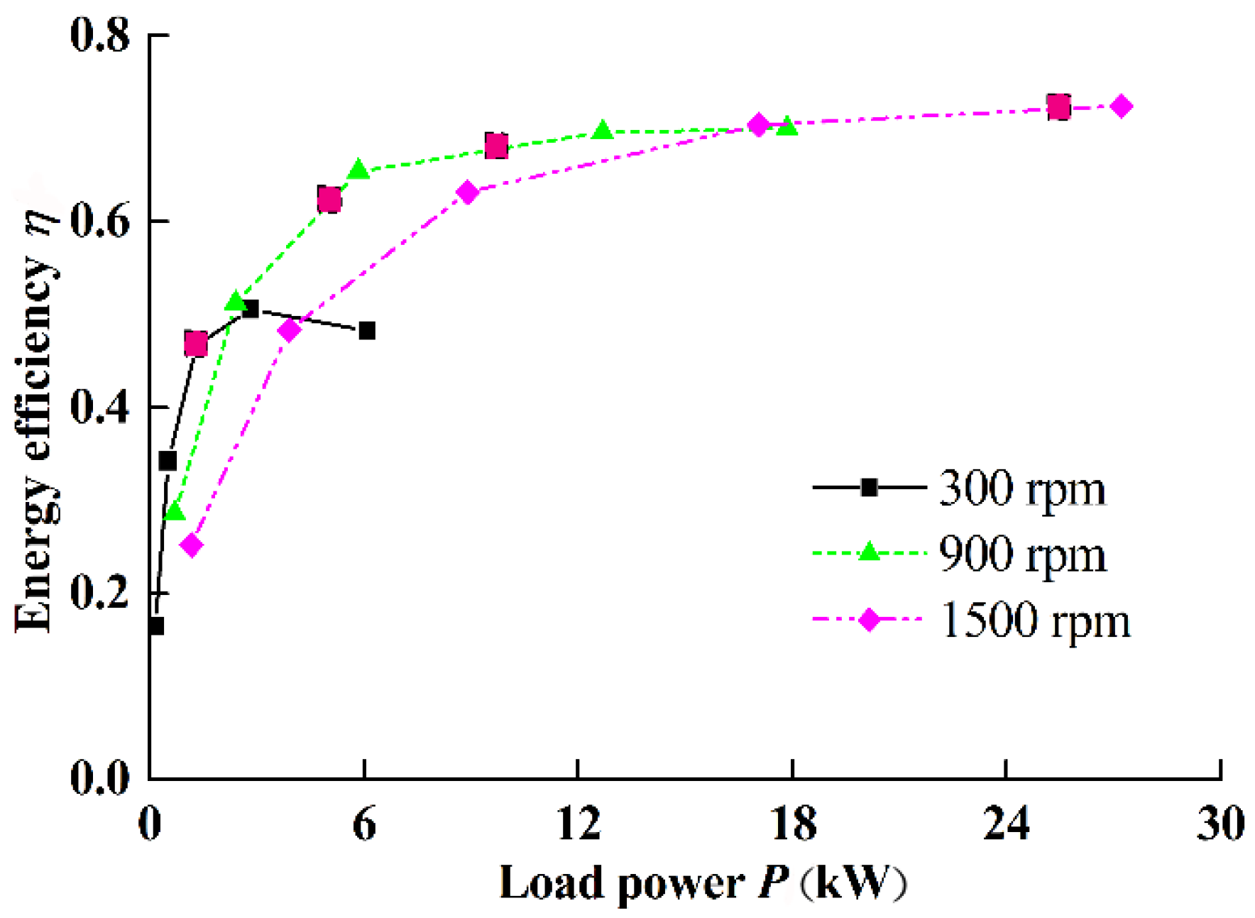
With Figure 7B,C, it can be seen that when the power source works under a light load, its energy efficiency is very low at only 48%. Additionally, when it works under a large load, the energy efficiency reaches up to 71%.
Next, the energy efficiency of the power source under different displacements and speeds is studied. During the test process, the displacement of the pump can be changed by changing the opening of the direction valve. Figure 8 gives the results of the energy efficiency of the power source under different load powers.
As shown in Figure 8, it can be seen that the energy efficiency of the pump increases with increasing displacement, and the energy efficiency of the motor increases with decreasing speed under light-load conditions.
Thus, it can be concluded that there are three problems for a pure variable-speed electro-hydraulic power source: one is that the flow response is relatively low when it starts with a large load; the second is that the energy efficiency of the total power source is low; and the third is that there may be some flow error when it works under difference loads.
According to the above problems of the pure variable-speed power source, the new power-source control principles should provide solutions to the problems.
4.2. Control Principles
As mentioned above, the designed power source can realize flow control and pressure control simultaneously.
4.2.1. Flow Control
In this paper, when the power source works with the flow-control concept, the pump speed is the control target to follow the flow command, and the pump works under the maximum displacement condition. Thus, under a certain flow requirement, when the flow requirement is given, the load power is relatively low, too. For example, when the pump speed is 300 rpm, the output power of the pump is no more than 20% of its rated power. Thus, according to the data shown in Figure 5 and Figure 6, compared with the pure variable-displacement system, the energy efficiency of the power source can be improved.
4.2.2. Pressure Control
As shown in Figure 1, the pressure of the system can be controlled by the variable-displacement pressure-compensated pump. In order to make the hydraulic pump work at a large displacement, to improve the power-source efficiency, the motor should work at a lower speed when the flow demand is satisfied. Moreover, in order to ensure the dynamic characteristics of the pressure response, it is necessary to ensure that the hydraulic pump does not work at maximum displacement. Therefore, under pressure control conditions, the pressure is controlled with the variable-displacement pressure-compensated pump and the speed is decreased to the lowest limit at a predefined rate. When the hydraulic pump displacement does not reach a certain value, the motor works under a low speed, and when it exceeds the set value, the set speed value increases to ensure adequate flow output.
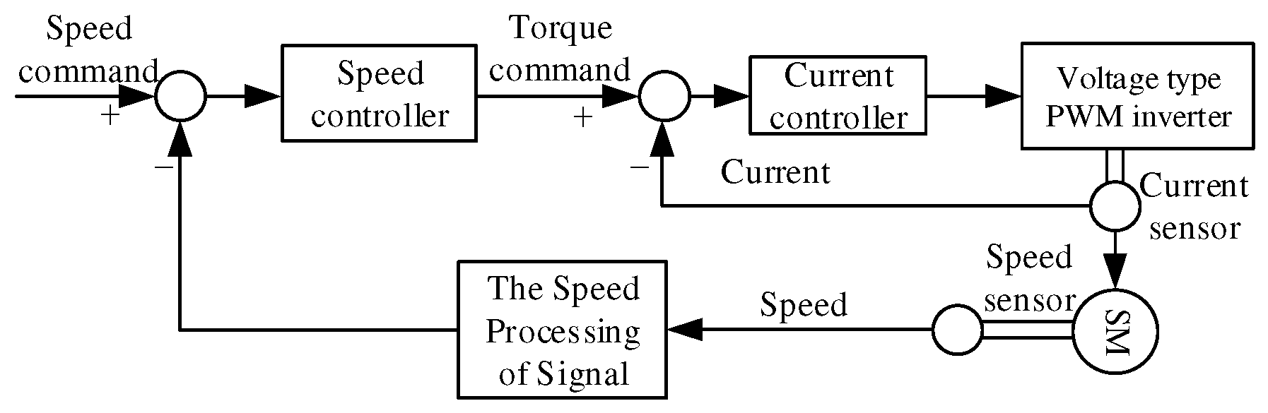
In the variable-speed asynchronous motor speed-control system, the control system is mainly composed of the current controller and the speed controller. The current controller controls the motor torque, and the speed controller controls the variable-speed asynchronous motor speed. The current control capability determines the torque performance of the variable-speed asynchronous motor, which is the main determinant of the dynamic response. The current feedback is very important, so the current inner ring and the speed outer ring control systems are primarily used to establish the variable-speed asynchronous motor control model, as shown in Figure 9.
5. Experimental Results of the New Power Source
5.1. Pressure-Control Characteristics
5.1.1. Influence of the Pump Speed on the Pressure Control Performance
The experimental device consists of a variable pump (Bosch Reoxth SYDFE1-71) and an AC motor driven by a frequency converter to form the main system. The load pressure is adjusted through a throttle valve, and the output pressure of the pump is determined by the Kistler model 4043A piezoresistive pressure sensor, which detects static or dynamic pressure up to 5 kHz (range is 250 bar). The time-recorded sampling of the pressure signal is performed by the ECON signal acquisition analyzer. The sampling frequency is 24 KHz, and a Hanning filter is applied.
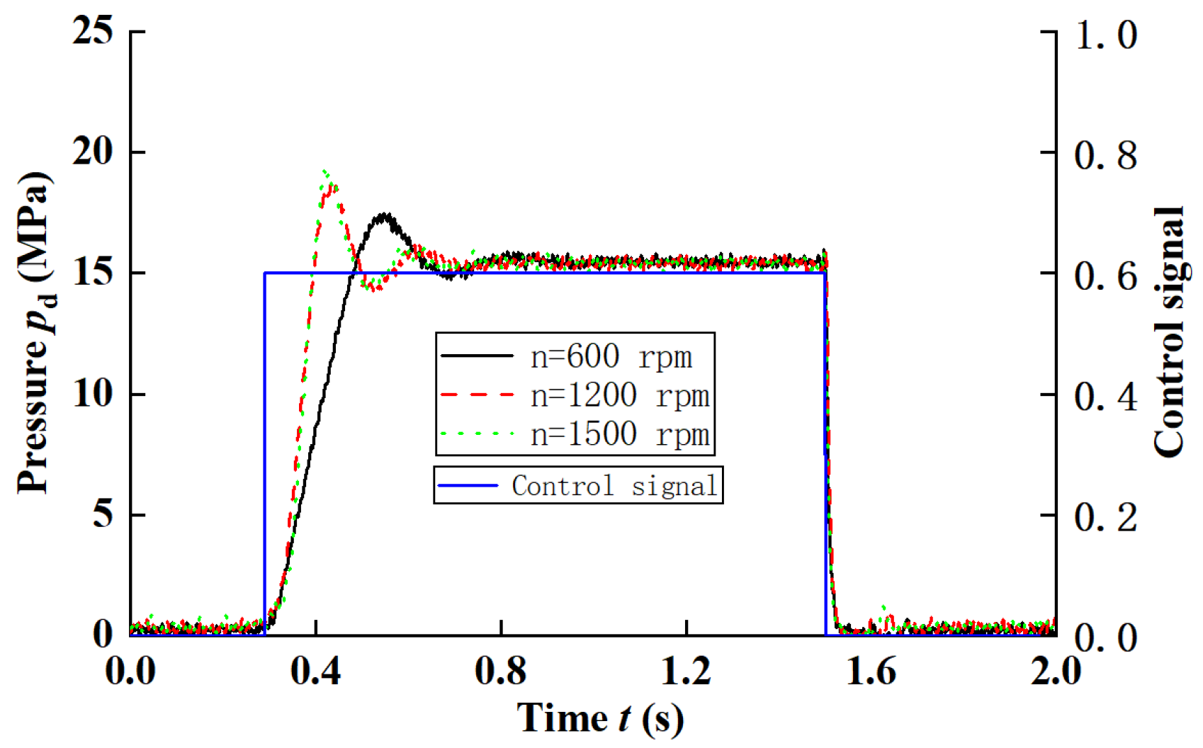
Firstly, the influence of the pump speed on the pressure control performance was studied. During the test process, the pressure of the relief valve was set to 25 MPa; a given square-wave control signal, which was set at 15 MPa, was applied to the pump pressure control valve; and the proportional direction valve was used as the loading valve with a 30% opening. The dynamic characteristic curve of pressures is described in Figure 10.
During the experimental process, the pressure control signal was set at 15 MPa at 0.3 s. At 1.5 s, the control signal of the pump was set at 0 MPa. Meanwhile, the swash plate angle of the proportional variable-displacement pressure-compensated pump was decreased to reduce the output flows, then the load pressure became lower.
Additionally, the pressure response time decreases along with the speed rapidly increasing, and the overshoot of pressure under a low speed is lower than that when the speed is about 1500 rpm.
5.1.2. Pressure Response with Variable Speed
The main purpose of this paper is to improve the energy efficiency of the electro-hydraulic power source by reducing the speed of the motor on the basis of ensuring its dynamic characteristics. The pressure control of the hydraulic power source can be divided into pressure maintenance and pressure control with the flow output. Under the condition of pressure maintenance, the speed of the motor is set to 300 rpm, so as to reduce its energy consumption.
Figure 11 gives the pressure control performance compared with the variable speed and fixed speed, when the load changes by changing the opening of the proportional directional valve, as shown in Figure 6.
From Figure 1, we can see that compared with the fixed-speed control, there is a large pressure impact when the load changes, and the response is relatively slow; however, it can still meet the system’s needs.
Specific operations were: close long-distance pressure pilot valve and the electromagnetic proportional directional valve completely; adjust the opening pressure of electromagnetic overflow valve to exceed the regulated pressure of internal constant-pressure valve DR; swift electromagnetic overflow valve on and off in turn so that internal pressure unloading was realized; and adjust the pressure of the internal constant-pressure valve DR to 5MPa, 10MPa, and 15MPa, respectively. The test results were shown in Figure 12.
However, the use of variable speed can greatly reduce the power consumed by the system in a stable operation. Figure 13 gives the power consumed by the power source under the working condition of Figure 11. The power consumption is relatively small when the load is also relatively small with the variable-speed control. In 0–1 s, power consumption is about 6.1 kW with variable-speed control, while it is about 9.5 kW with fixed-speed control.
To sum up, using variable-speed control can effectively reduce the power consumption of the electro-hydraulic power source when the load power is relatively low.
5.2. Flow-Control Characteristics
5.2.1. Flow Compensation Control
From Figure 7, it can be seen that the maximum flow decreases with an increase in load pressure due to the speed and leakage changing. To control the output flows of the pump accurately, a load-pressure signal is fed back to the controller, and the leakages resulting from the increased load pressures can be compensated with increasing the speed; this will reduce the influence of load pressure on the pump output flow rate. Figure 14 describes the test results of the flow compensation method.
It can be seen that the flow error can be reduced with the proposed compensation strategy.
5.2.2. Dynamic Response Improvement of the Power Source
A variable-speed power source often starts with a full load or heavy load, and sometimes, its dynamic response may not meet the system requirements. With the system shown in Figure 1, the dynamic characteristics of the power source under different load condition are studied. The flow output of the pump is detected to characterize the dynamic response.
During test process, the initial motor speed is set at 0 r/min. The load pressure is set at 0 and 18 MPa, and the maximum start speed of the motor is set at 1500 r/min. Figure 11 gives the compared data of the flow response under different conditions.
As shown in Figure 15, when the motor starts under a load pressure of 0 MPa, the flow response time is about 0.55 s from the smallest to the largest. Additionally, the load pressure is about 18 MPa at 2.3 s. Thus, when the motor starts under a large load pressure, the flow response is not enough to use in a hydraulic system. When the electric motor starts, high-pressure oil in the accumulator will flow into the system through the inlet port of the pump, to accelerate the starting of the pump. When the motor speed reaches the set value, the accumulator will be closed. As shown in Figure 11, on the line with the identification of qf18r18, the pre-charge pressure of the accumulator is about 18 MPa, and the motor starts under a load pressure of 18 MPa; it can be seen that the response time is about 0.7 s, and the response time decreases with an increase in the maximum current of the motor.
As shown in Figure 15, when the motor starts under a load pressure of 0 MPa, the electric peak power is about 26.4 kW, which is about 36.4 kW under the load pressure of 18 MPa, and about 32.4 kW with the accumulator assisting.
5.3. Energy Efficiency of the Electro-Hydraulic Power Source
During the working process of the electro-hydraulic power source, the energy conversion process of the power source system is as follows: frequency converter–electric motor–pump. Generally, the energy efficiency of the frequency converter is about 95%, which is less affected by load condition. The energy efficiency of the electric motor is affected by the load and rotating speed, which is about 90% under the rated load and speed, and under partial load conditions, it would be less than 40%.
When the proportional variable-displacement pressure-compensated pump is under constant-pressure-cut mode, the load is in a pressure-maintaining status. Meanwhile, the pump only outputs pressures rather than flows, and it only needs to maintain the flows for internal circuit controls and leakages; thus, the system load power is low. Therefore, under this mode, the speed of the motor can be decreased to improve its energy efficiency.
In order to gain knowledge of the energy efficiency of the electro-hydraulic power source, it was tested based on the test system shown in Figure 6. Figure 16 shows the energy efficiency of the electro-hydraulic power source under pressure-maintaining status.
During the experimental process, the pilot pressure is set at 5 MPa, 10 MPa, 15 MPa, and 20 MPa, respectively; and the motor speed rises from 300 r/min to 1500 r/min. With the increasing of motor speed, the input power to the electric motor synchronously rises. When the speed drops from 1500 r/min to 300 r/min under different load pressures, the system energy consumption decreases by about 3 kW for each pressure level.
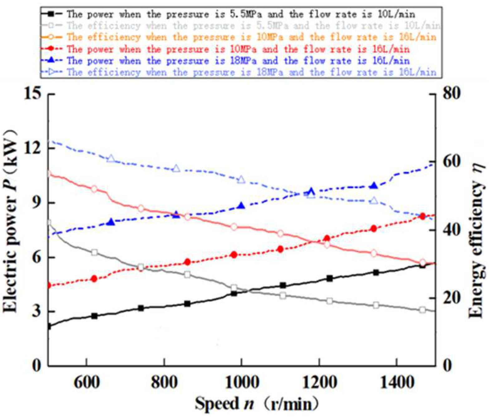
Figure 17 shows the curves of the motor input powers vs. speeds. If the load pressure is 5.5 MPa, the electric power consumed is about 1.5 kW, the motor speed is 450 r/min, and the flow rate at this time is 10 L/min. When the motor speed is 1500 r/min, the flow rate at this time is 16 L/min, and the power consumed is about 4.6 kW. If the load pressure is 10 MPa, the electric power consumed is about 4.1 kW under the speed of 450 r/min, and the flow rate at this time is 10 L/min. When the motor speed is 1500 r/min, the flow rate at this time is 16 L/min, and the power consumed is about 7.1 kW.
It can be concluded that the powers under the three conditions can be reduced by 2.9 kW each when the motor speed declines from 1500 r/min to 450 r/min. This kind of energy consumption is mainly caused by motor copper loss under different speeds. Under suitable conditions of the electro-hydraulic power source system, the lower the speed, the lower the energy consumption will be.
6. Conclusions
- The energy-efficient electro-hydraulic power source driven by a variable-speed motor was designed, and can match the working requirements of the actuator and greatly reduce system pressure fluctuation and system energy consumption when the heavy-duty actuator moves at high speed.
- Aiming to solve the problems of slow start-up and the large current impact of a variable-frequency motor with a load, a scheme for setting an accumulator to assist in starting at the oil suction port of the pump is proposed; this can effectively improve the dynamic response speed of the motor. To solve the problem, the idea of segmented speed control of the variable-frequency motor was designed. After testing and verification, using the designed variable-speed and variable-displacement control strategy, the dynamic response of the electro-hydraulic power source can be basically consistent with simple variable-displacement control; for example, the system starting time can be shortened from 2.8 s to 0.7 s under the load pressure of 18 MPa. Additionally, the relevant dynamic response of the pump output flows becomes faster.
- Load pressure feedback controlling is used to compensate for the motor speed and the internal leakage caused by changing load pressure, which could achieve given flow controls. With changes in load pressure, the influence of output flow is smaller, and the control accuracy error is no more than 0.5% when the pressure changes by 20 MPa.
- For the electro-hydraulic power source composed of a variable-displacement pressure-compensated pump driven by a variable-speed asynchronous motor, the system energy consumption will reduce by 3 kW when the motor speed changes from 1500 r/min to 300 r/min under the condition of pressure maintenance. In a constant-pressure mode, the energy consumption of the power source can be significantly reduced by combining the controls between the motor speed and the pump flow in a low-speed and large-displacement manner.
- The electro-hydraulic power source composed of the variable-speed control axial piston pump, and the research work that went into replacing the axial piston pump with the proportional constant-pressure pump, mainly focus on the drive device composed of the frequency converter and the servo motor. Further research will be conducted on the dynamic response, control method, energy efficiency, and engineering application background of a proportional constant-pressure pump power source composed of driving sources such as reluctance motors and engines.
Author Contributions
Conceptualization, Z.Y. and L.Q.; methodology, Z.Y.; software, Z.Y. and L.G.; validation, Z.Y., L.G. and L.Q.; formal analysis, Z.Y.; investigation, Z.Y.; resources, Z.Y.; data curation, Z.Y.; writing—original draft preparation, Z.Y.; writing—review and editing, Z.Y.; visualization, Z.Y.; supervision, Z.Y.; project administration, Z.Y.; funding acquisition, Z.Y. All authors have read and agreed to the published version of the manuscript.
Funding
We acknowledge financial support from the applied basic research program of Shanxi Province, China (201901D111300).
Institutional Review Board Statement
The study was conducted in accordance with the Declaration of Helsinki, and approved by the Institutional Review Board of University, Jinzhong.
Informed Consent Statement
Not applicable.
Data Availability Statement
Not applicable.
Acknowledgments
The authors are grateful for the financial support of the applied basic research program of Shanxi Province, China (201901D111300).
Conflicts of Interest
The authors declare no conflict of interest.
Abbreviations
| B | Viscous damping coefficient | Nm/(rad/s) |
| Dp | displacement of the pump | mL/r |
| Dn | the quantitative pump displacement | mL/r |
| fs | Frequency of the electric power source | Hz |
| iqs | stator current | A |
| J | rotational inertia | kgm2 |
| Lm | magnetic inductance | H |
| Lr | rotor self-inductance | H |
| np | polar number | - |
| s | slip ratio | - |
| pa1 | pre-charge pressure | MPa |
| pa2 | working pressure | MPa |
| p3 | minimum working pressure of accumulator | MPa |
| pd | pressure of the pump | MPa |
| Pp | output power of pump | kW |
| Ta1 | gas temperature under inflation pressure stage | °C |
| Ta2 | gas temperature under supercharging pressure stage | °C |
| Ta3 | gas temperature under supercharging pressure stage | °C |
| TL | load torque | Nm |
| Va1 | gas volume of the accumulator under inflation pressure stage | L |
| Va2 | gas volume of the accumulator under supercharging pressure stage | L |
| Va3 | gas volume of the accumulator under minimum working pressure stage | L |
| n | angular speed of motor | r/min |
| ηpm | mechanical efficiencies of the pump | - |
References
- Chu, M.H.; Kang, Y.; Chen, Y.W.; Chang, Y.P. The Swashplate Angle Control of a Variable Displacement Pump with an Electro-Hydraulic Proportional Valve. Mater. Sci. Forum 2008, 594, 389–400. [Google Scholar] [CrossRef]
- Achten, P. Dynamic High-frequency Behaviour of the Swash Plate in a Variable Displacement Axial Piston Pump. Proc. Inst. Mech. Eng. Part I J. Syst. Control. Eng. 2013, 227, 529–540. [Google Scholar] [CrossRef]
- Mondal, N.; Saha, R.; Mookherjee, S.; Sanyal, D. A Novel Method to Design Pressure Compensator for Variable Displacement Axial Piston Pump. Proc. Inst. Mech. Eng. Part E J. Process Mech. Eng. 2019, 233, 314–334. [Google Scholar] [CrossRef]
- Dean, P.T.; Fales, R.C. Modern Control Design for a Variable Displacement Hydraulic Pump. In Proceedings of the 2007 American Control Conference, New York, NY, USA, 11–13 July 2007; pp. 3535–3540. [Google Scholar]
- Wei, J.; Guo, K.; Fang, J.; Tian, Q. Nonlinear Supply Pressure Control for a Variable Displacement Axial Piston Pump. Proc. Inst. Mech. Eng. Part I J. Syst. Control. Eng. 2015, 229, 614–624. [Google Scholar] [CrossRef]
- Helduser, S. Electric-hydrostatic Drive—an Innovative Energy-saving Power and Motion Control System. Proc. Inst. Mech. Eng. Part I J. Syst. Control. Eng. 1999, 213, 427–437. [Google Scholar] [CrossRef]
- Haihong, H.; Jin, R.; Li, L.; Liu, Z. Improving the Energy Efficiency of a Hydraulic Press via Variable-speed Variable-displacement Pump Unit. J. Dyn. Syst. Meas. Control. 2018, 140, 111006. [Google Scholar]
- Willkomm, J.; Wahler, M.; Weber, J. Potentials of Speed and Displacement Variable Pumps in Hydraulic Applications. In Proceedings of the 10th International Fluid Power Conference, Dresden, Germany, 8–10 March 2016; pp. 379–392. [Google Scholar]
- Helbig, A. Injection Moulding Machine with Electric Hydrostatic Drives. In Proceedings of the 3rd International Fluid Power Conference, Aachen, Germany, 5–6 March 2002; pp. 67–82. [Google Scholar]
- Zhang, H.; Ren, L.; Gao, Y.; Jin, B. A Comprehensive Study of Energy Conservation in Electric-hydraulic Injection-molding Equipment. Energies 2017, 10, 1768. [Google Scholar] [CrossRef] [Green Version]
- Ge, L.; Quan, L.; Zhang, X.; Zhao, B.; Yang, J. Efficiency Improvement and Evaluation of Electric Hydraulic Excavator with Speed and Displacement Variable Pump. Energy Convers. Manag. 2017, 150, 62–71. [Google Scholar] [CrossRef]
- Kazmeier, B.; Feldman, D.G. Electro-hydrostatic Low Power Linear Driver-system Performance and Controls to Minimize Power Consumption. In Proceedings of the 3rd International Symposium on Fluid Power Transmission and Control, Harbin, China, 7–9 September 1999; International Academic: Beijing, China, 1997; pp. 113–119. [Google Scholar]
- Chiang, M.H.; Chien, Y.W. Parallel Control of Velocity Control and Energy-saving Control for a Hydraulic Valve-controlled Cylinder System Using Self-organizing Fuzzy Sliding Model Control. JSME Int. J. 2003, 46, 224–231. [Google Scholar] [CrossRef] [Green Version]
- Shen, H.K.; Nie, M.; Zhi, S.D.; Bo, J. Study on High Dynamic Variable Speed Hydraulic Control System. Appl. Mech. Mater. 2013, 271–272, 625–631. [Google Scholar] [CrossRef]
- Tadej, T.; Vito, T.; Darko, L. Energy-savings Using Maximum Efficiency Control within Electro-hydraulic Drive Technology. In Proceedings of the International Conference on Sustainable Energy &Environmental Protection (SEEP 2013), Maribor, Slovenia, 20–23 August 2013; pp. 153–161. [Google Scholar]
- Lovrec, D.; Faber, F. Electro-hydraulic Pressure Control by a Self-adjusting Proportional Derivative Controller. Exp. Tech. 2006, 30, 57–63. [Google Scholar] [CrossRef]
- Xu, M.; Yu, X.; Wu, X.; Chen, G.J. State-space Modeling and Analysis of Power Assist Unit-based Variable-speed pump-controlled-motor drive system. J. Braz. Soc. Mech. Sci. Eng. 2018, 40, 7. [Google Scholar] [CrossRef]
- Xu, B.; Cheng, M.; Yang, H.; Zhang, J.; Sun, C. A Hybrid Displacement/Pressure Control Scheme for an Electro-hydraulic Flow Matching System. IEEE/ASME Trans. Mechatron. 2015, 20, 2771–2782. [Google Scholar] [CrossRef]
- Tian, Y.; Wu, S.L. Theoretic analysis and experiment of valveless electro-hydraulic servo system. China Mech. Eng. 2003, 14, 1822–1823. [Google Scholar]
- Yan, Z.; Quan, L.; Zhang, X. Simulation and experimental research on dynamic characteristics of electro-hydraulic proportional variable pump. Trans. Chin. Soc. Agric. Mach. 2015, 47, 436–443. [Google Scholar]
- Liu, B.; Yan, Z.; Ge, L.; Quan, L. Electric Drive Hydraulic Power Source Characteristics of Small Hydraulic Excavator. Trans. Chin. Soc. Agric. Mach. 2019, 50, 387–393. [Google Scholar]
- Xia, L.; Quan, L.; Ge, L.; Hao, Y. Energy efficiency analysis of integrated drive and energy recuperation system for hydraulic excavator boom. Energy Convers. Manag. 2018, 156, 680–687. [Google Scholar] [CrossRef]
- Ge, L.; Quan, L.; Zhang, X.; Dong, Z.; Yang, J. Power matching and energy efficiency improvement of hydraulic excavator driven with speed and displacement variable pump. Chin. J. Mech. Eng. 2017, 32, 100. [Google Scholar] [CrossRef] [Green Version]
- Gamez-Montero, P.J.; Antoniak, P.; Castilla, R.; Freire, J.; Krawczyk, J.; Stryczek, J.; Codina, E. Magnet-Sleeve-Sealed Mini Trochoidal-Gear Pump Prototype with Polymer Composite Gear. Energies 2017, 10, 1458. [Google Scholar] [CrossRef] [Green Version]
- Fei, S.; Hong, J.; Yanbo, P.; Chen, L. Numerical simulation and prototype experiment of integrated electrohydraulic pump. Proc. Inst. Mech. Eng. Part C J. Mech. Eng. Sci. 2022. [Google Scholar] [CrossRef]
- Massimo, R. Models for Flow Rate Simulation in Gear Pumps: A Review. Energies 2017, 10, 1261. [Google Scholar]
- Ivantysyn, J.; Ivantysynova, M. Hydrostatic Pumps and Motors: Principle, Design, Performance, Modeling, Analysis, Control and Testing; Tech Books International: New Delhi, India, 2001. [Google Scholar]
Figure 1.
Principle of the electro-hydraulic power source.

Figure 2.
Working principle of the assisted starting concept.

Figure 3.
Relationship between angular acceleration and the load torque.

Figure 4.
Square-wave signal for flow control.

Figure 5.
Dimensionless efficiency curve of axial piston pump.

Figure 6.
Test bench.

Figure 7.
Working performance of a pure variable-speed electro-hydraulic power source.

Figure 8.
Energy efficiency of a variable-speed and -displacement electro-hydraulic power source.

Figure 9.
The block diagrams of the control system.

Figure 10.
Dynamic characteristic curve of pressures under different speeds.

Figure 11.
Pressure control compared with variable and fixed speed.

Figure 12.
The characteristics of pressure response under an internal unloading condition.

Figure 13.
Power consumption compared with variable and fixed speed.

Figure 14.
Constant flow characteristics under different pressures.

Figure 15.
Dynamic response of pump output flows.

Figure 16.
Motor output power under pressure-maintaining status.

Figure 17.
Variable-speed and -displacement compound motor input power.


Table 1.
The parameters of the values.
| Parameters | Value |
|---|---|
| Cs | 0.8 × 10⁻⁹ |
| CV | 0.2 × 10⁶ |
| Cf | 0.01 |
| Pout | 45 kW |
| ωm | 1480 r/min |
| Rs | 0.084 Ω |
| Rr | 0.084 Ω |
| Ls | 0.3012 mH |
| Lr | 0.3012 mH |
| Lm | 11.2 H |
| J | 0.046 kg·N2 |
| v | 45.88 cSt |
| ρ | 0.85 kg/L |
| μ | 0.039 Pa·s |
| np | 2 |
Publisher’s Note: MDPI stays neutral with regard to jurisdictional claims in published maps and institutional affiliations. |
© 2022 by the authors. Licensee MDPI, Basel, Switzerland. This article is an open access article distributed under the terms and conditions of the Creative Commons Attribution (CC BY) license (https://creativecommons.org/licenses/by/4.0/).
Share and Cite
MDPI and ACS Style
Yan, Z.; Ge, L.; Quan, L. Energy-Efficient Electro-Hydraulic Power Source Driven by Variable-Speed Motor. Energies 2022, 15, 4804. https://0-doi-org.brum.beds.ac.uk/10.3390/en15134804
AMA Style
Yan Z, Ge L, Quan L. Energy-Efficient Electro-Hydraulic Power Source Driven by Variable-Speed Motor. Energies. 2022; 15(13):4804. https://0-doi-org.brum.beds.ac.uk/10.3390/en15134804
Chicago/Turabian StyleYan, Zheng, Lei Ge, and Long Quan. 2022. "Energy-Efficient Electro-Hydraulic Power Source Driven by Variable-Speed Motor" Energies 15, no. 13: 4804. https://0-doi-org.brum.beds.ac.uk/10.3390/en15134804
Note that from the first issue of 2016, this journal uses article numbers instead of page numbers. See further details here.