1. Introduction
Increasingly stricter regulations on internal combustion engines (ICEs) pollutant emissions are pushing research efforts towards non-conventional combustion systems. In order to improve the efficiency of spark ignition (SI) engines, it is possible to replace throttling at partial loads with a lean or diluted mixture, or with a stratified mixture when adopting a direct injection system. While these strategies grant reduced fuel consumption, some issues related to pollutant emissions still remain. Low temperature combustion (LTC) represents a promising way to solve the above-mentioned issues of ICEs [
1]. LTC technology blends the best features of Diesel and SI combustion by igniting a homogeneous lean mixture; therefore, specific fuel consumption and emissions of nitrogen oxides (NOx), carbon monoxide (CO) and particulate matter (PM) are reduced.
Pre-chamber jet ignition [
2,
3,
4,
5,
6] represents one of the most promising techniques to achieve LTC combustion. The spark ignites the air-fuel mixture inside the small volume of the pre-chamber: the flame front propagates inside the pre-chamber and enters the main combustion chamber in the form of turbulent flame jets, which in turn ignite the fresh charge in the main chamber. The two volumes are connected through a small diameter duct or through small orifices, whose sizing is crucial [
7], as they determine the shape and structure of the jets which act as distributed ignition sources. The use of a pre-chamber is helpful in reducing the ignition delay and increasing the flame front propagation speed [
8,
9], thanks to the increase in turbulent transport phenomena. Such features allow the ignition of very lean premixed mixtures [
10] without the use of in-cylinder stratification or dual-fuel systems as the reactivity of the mixture is increased. The main challenge is obtaining an almost stoichiometric mixture inside the pre-chamber when a lean mixture is used inside the main chamber. Two different categories of pre-chamber have been developed so far, depending on the fueling system:
Active (or stratified): the pre-chamber is provided with a dedicated injector in addition to the main one [
11], which guarantees stoichiometric conditions inside the pre-chamber at each engine operation, but at the same time it increases system complexity;
Passive: the pre-chamber is fueled during the compression stroke by the air-fuel mixture coming from the cylinder.
Passive pre-chambers are simple to install. Commonly they can be screwed in the spark plug filleting without changing the cylinder head. However, they need an accurate set-up of the injection system (in case of direct injection [
12]) or the use of a not too lean mixture (in case of indirect injection). Generally, spray-guided direct injectors are used, in such a way as to directly fill the pre-chamber with fuel. However, passive pre-chambers have been applied to lean natural gas PFI engines. In this case, the ignition of a fuel-lean mixture inside the pre-chamber is possible thanks to the high turbulence and the slow flow field in the spark gap zone [
13].
In the more traditional case of slow natural gas engines for power generation, where the size of valves is not so relevant, the pre-chamber shape is usually stumpy [
14] and can fit easily above the engine’s head. Large and flattened shapes are also used in two-stroke engines, thanks to the absence of head valves [
15,
16]. Having a low height-to-diameter ratio, they seem to facilitate the scavenging process [
17], especially when using multiple orifices. In the case of high-performance engines, the lower space available between valves imposes the use of elongates shapes [
18,
19], characterized by a big volume on top and a cylindrical or conical channel that communicates with the combustion chamber through one or more small orifices. Having a high height-to-diameter ratio, an increase of the gas trapping inside the pre-chamber may occur, which can hamper the functioning of the device. There is a lack of examples in the technical literature concerning the analysis of passive pre-chambers for high-performance gasoline engines by means of high-fidelity three-dimensional simulations of the combustion process, due to the higher difficulty of guaranteeing the ignitability of the mixture.
In the present study, the potential of using a passive pre-chamber for enhancing the combustion process of a 4-stroke SI engine was investigated by means of 3D CFD numerical analyses. The test case is a high-performance 430 cm3 engine for off-road motorcycle application, in which a port fuel injection system (PFI) is used to supply gasoline as fuel. A preliminary CFD analysis was carried out in order to calibrate and validate the combustion model against experimental data, considering the engine in its baseline configuration (i.e., without pre-chamber).
The aim of the study was twofold. On the one hand, the validation of the numerical approach by means of high-fidelity three-dimensional simulations of the combustion process by adopting a detailed chemistry solver with a reduced reaction mechanism, in order to find the most suitable trade-off between accuracy and computational cost. On the other hand, the evaluation of different pre-chamber configurations, by varying the aspect ratio and the orifices’ diameter, in view of enhancing the combustion process. Eventually, since the use of a pre-chamber can extend the air-fuel mixture ignition limits, an additional sensitivity on the air-fuel ratio was carried out, in order to investigate engine performance under lean conditions.
2. Materials and Methods
2.1. Test Case
The test case is a Betamotor 430 cm
3, single-cylinder, 4-stroke engine for motorcycle application. Engine data are summarized in
Table 1. The operating point corresponding to maximum power was considered for the pre-chamber analyses of the present study, although the numerical setup was additionally validated for lower rpm. It is worth pointing out that the real engine does not feature a pre-chamber in its baseline configuration; the effects of different passive pre-chamber configurations were only tested by means of numerical analysis, as described in the following sections.
The engine was tested on the 80-kW dynamic test bench of the LINEA laboratory of the Department of Industrial Engineering of the University of Florence. Torque and power were measured at the gearbox output, and both averaged and indicating measurements were carried out in order to carefully analyze the combustion process, the dynamic pressures inside the intake and exhaust manifolds, and the engine performance. In particular, a Kistler 6054A piezoelectric sensor was adopted to measure the dynamic in cylinder pressure. Indicating data were acquired using the AVL IndiMicro measurement system and processed through the AVL Indicom software.
2.2. Numerical Setup
The numerical activity of this study was divided into two parts. In the first part, the numerical model of the real engine in its baseline configuration was calibrated and validated against experimental data, for two operating points. In the second part, the previously validated numerical setup was employed for dedicated sensitivity analyses on both the geometrical configuration of the pre-chamber and the equivalence ratio of the air-fuel mixture. In order to investigate the combustion process, flame front propagation and combustion duration were analyzed for every simulation.
The commercial software CONVERGE CFD (version 3.0.19) was employed for the present study. The software automatically generates a cartesian grid at run-time during simulation, according to user-defined grid control parameters, removing the typical step of manually generating the mesh; indeed, only a Stereo Lithography (STL) file of the geometry was required for setting up the test case. Moreover, the meshing system features Adaptive Mesh Refinement (AMR); the computational grid is automatically refined based on fluctuating and moving variables, such as temperature, velocity, and species.
For the 3D numerical simulations, the turbulent flow was described by the time-dependent unsteady RANS equations, and the RNG
model was used for turbulence modelling [
19,
20,
21]. PISO algorithm handled pressure-velocity coupling and a pressure-based solver was employed. A second-order upwind numerical scheme was used for the spatial discretization of the governing equations. Convergence residuals were set to 10
−5 for all the solved quantities. A variable time-step was employed, having set its minimum value at 10
−8 s.
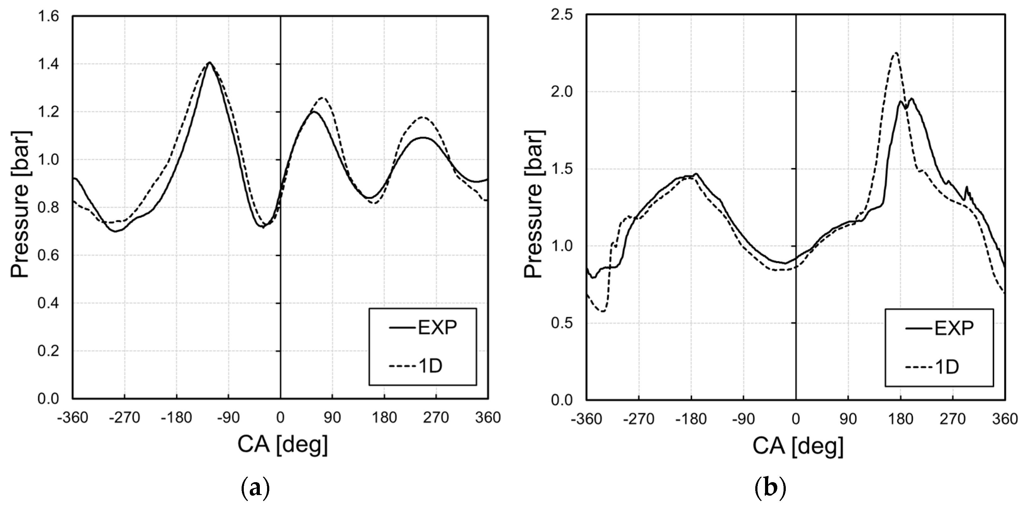
Boundary conditions for the 3D simulations were obtained from a 1D model of the baseline engine. This model was developed in GT-Power framework and calibrated with available experimental data, as reported in
Figure 1, where the intake and exhaust pressure trends are compared.
Combustion phenomena were modelled through the SAGE detailed chemistry combustion model [
19,
22]. The detailed chemistry solver uses local flow conditions to calculate reaction rates based on species chemical kinetics properties, which are contained in a reaction mechanism file. Specifically, in order to limit the computational effort of the activity, a reduced mechanism for iso-octane (IC
8H
18) was employed. The mechanism featured 41 species and 124 reactions. The adoption of a “high fidelity” combustion model was necessary in order to guarantee a suitable prediction capability when simulating the combustion for the pre-chamber geometry cases.
Since the detailed chemistry solver is fully coupled to the flow solver, correctly modelling the scavenging process and properly resolving the flow field was paramount. To this aim, every CFD analysis that was carried out in this study is the result of simulating three engine cycles. The scavenging process is modelled within the first two cycles.
Here, a user-defined function (UDF) is employed to model the effects of combustion: this saves calculation time, since the UDF does not make use of a detailed chemistry solver. Instead, it artificially raises in-cylinder pressure and temperature and modifies the species mass fractions according to single-step chemical reactions. The resulting combustion is inaccurate and non-predictive, but made it possible to take into account pressure, temperature, and species variations to enhance the accuracy of the scavenging simulation. Eventually, the results of the scavenging calculations were employed in the initialization of the third cycle, which featured the detailed-chemistry combustion modelling.
2.3. Mesh Sensitivity Analysis
A mesh sensitivity analysis was carried out for the scavenging simulation, specifically, three different meshes were tested (
Table 2). The base mesh definition was chosen based on the authors’ previous experience [
17,
23,
24,
25].
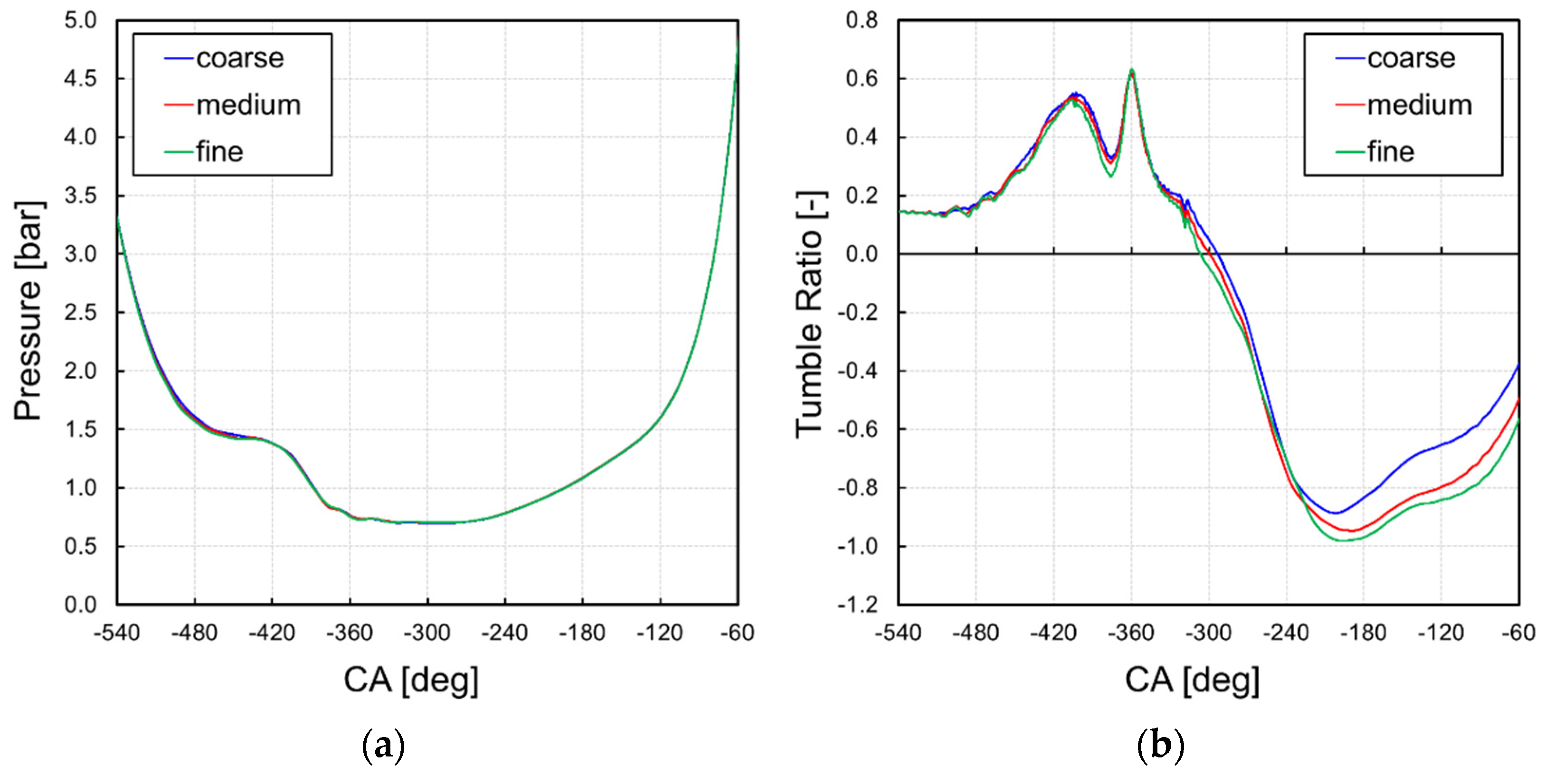
In terms of calculated in-cylinder pressure, similar results were obtained regardless of the employed mesh, as shown in
Figure 2a. Conversely, some differences arose in terms of tumble ratio. As shown in
Figure 2b, tumble ratio values were similar for the three meshes during the exhaust and overlap phases. However, as the intake valves open, some differences arose, and the coarse mesh returned higher values of tumble ratio with respect to the other meshes.
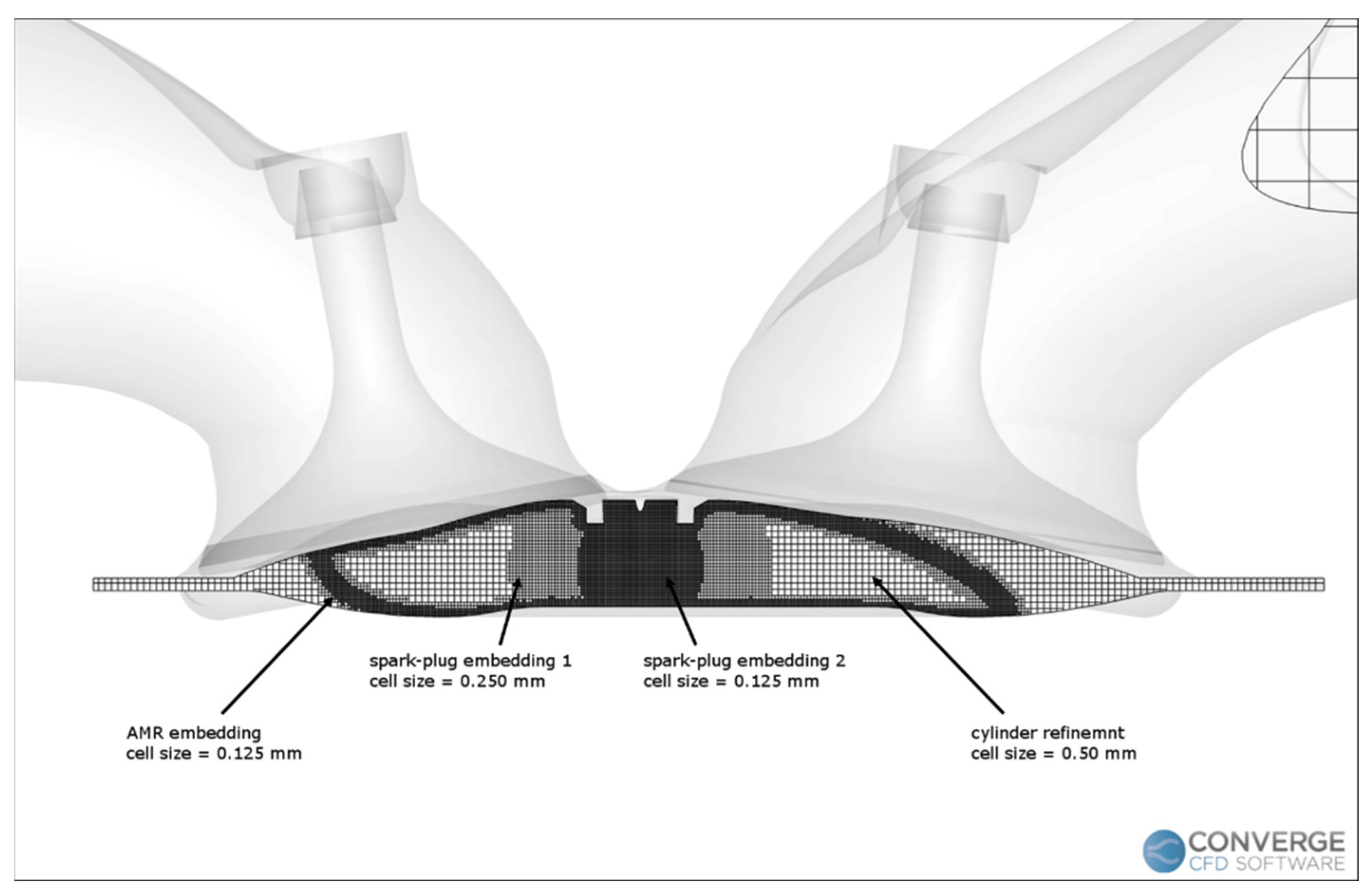
It is worth pointing out that the fine mesh made it possible to take into account smaller scale phenomena, reducing the filtering of the grid size, thus granting a more accurate modelling of flow structures. For this reason, the fine mesh was employed for this activity. It is worth pointing out that the employed mesh was further refined (
Figure 3) during the combustion process, in order to ensure a correct modelling of the ignition and flame propagation.
Table 3 reports the properties of the mesh that was used for both the scavenging and combustion calculations with CONVERGE CFD. In particular, during combustion a very refined region was defined in the spark plug region, together with a high-resolution AMR strategy based on the temperature gradients, both based on a minimum grid size of 0.125 mm, which is the finest possible size recommended by the software developers.
2.4. Numerical Test Plan
Three different air-fuel equivalence ratio (λ) values were considered for the present study, ranging from stoichiometric conditions to leaner conditions (i.e., air-fuel equivalence ratio equal to 1.2 and 1.4). The engine was tested in its baseline configuration (i.e., without any pre-chamber) and with four different pre-chambers, varying for aspect ratio and nozzles diameter (
Table 4).
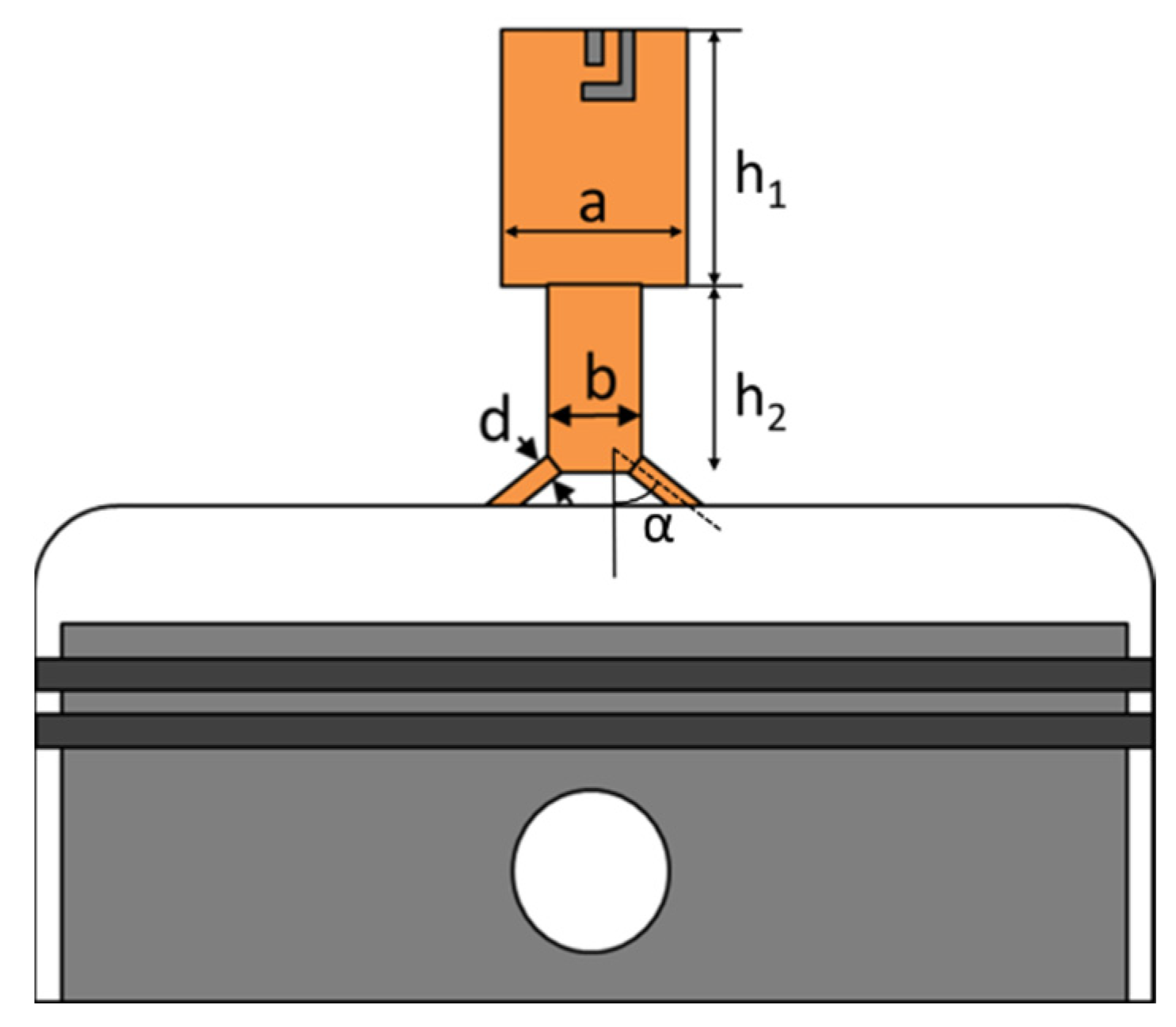
Figure 4 shows a schematic with the main geometric parameters of the passive pre-chamber: aspect ratio (AR) is the ratio of the total height to the maximum width, while
d is the nozzle diameter. For reasons of confidentiality, the dimensional values cannot be shown in the present paper.
Once the employed combustion model was calibrated and validated against experimental data, a sensitivity analysis on different pre-chamber aspect ratio was carried out at stoichiometric conditions. Then, the effects of the nozzle’s diameter were investigated for the pre-chamber with the highest aspect ratio. Starting from the reference diameter (
d0), the holes were increased by a factor 1.1 and 1.2, respectively. Eventually, the same test was carried out for leaner mixture conditions and the results were compared against the baseline engine configuration.
Table 5 summarizes the configurations that were investigated in this study.
3. Results and Discussion
3.1. Calibration and Validation of the Combustion Model
As previously stated, a reduced mechanism for iso-octane was employed to model the combustion process. This, together with the fact that the actual fuel composition most likely differs from pure iso-octane, made it necessary to fine-tune several turbulent combustion parameters in order to gain a good agreement with experimental data. Indeed, the calibration of the combustion model was carried out by varying the spark parameters, a combustion model parameter called reaction multiplier (), which is a scale factor for reaction rates, and the turbulent Schmidt number ().
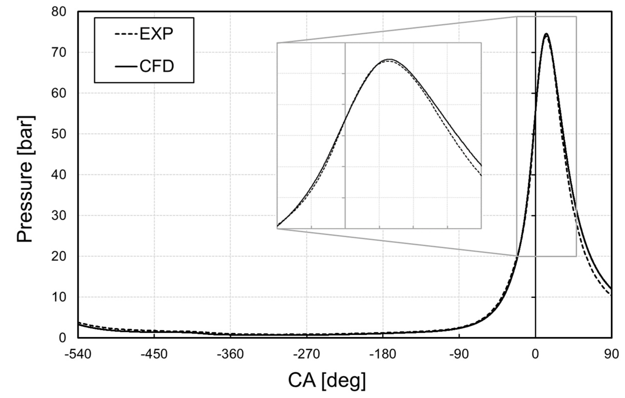
Figure 5 shows the comparison between the calibrated model and experimental data in terms of in-cylinder pressure. The CFD results are quite accurate, especially during the intake phase and compression phase of the mixture. It is also apparent that a good agreement was achieved during the ignition and turbulent combustion phases. The difference between numerical results and experimental measurements is less than 1% and the pressure peak was obtained at same crank angle as the experimental one. The CFD model tends to overestimate in-cylinder pressure during the last phase of combustion. During this phase, wall temperature values, fuel LHV, as well as some differences in the geometrical model due to the defeaturing operation, may affect CFD results. Nevertheless, in-cylinder pressure was well represented, and the numerical setup was deemed suitable to analyse the combustion process of the engine.
Figure 6 shows the evolution of the burned mass fraction for the calibrated model compared with experimental data. Good accuracy was achieved, especially during the turbulent combustion phase, which is represented by the middle of the curve, from 10% to 70% of burned air-fuel mixture.
The combustion model was calibrated at the operating point corresponding to maximum power. With the aim of assessing the predictivity of the CFD model, another operating point was simulated. Indeed, adequate boundary conditions from the 1D engine model were set in order to model the engine running at 4000 rpm, full load. On the other hand, combustion model-related parameters were left unchanged, except for the crank angle duration of the energy sources in the spark ignition model, which were changed according to the lower rotational speed.
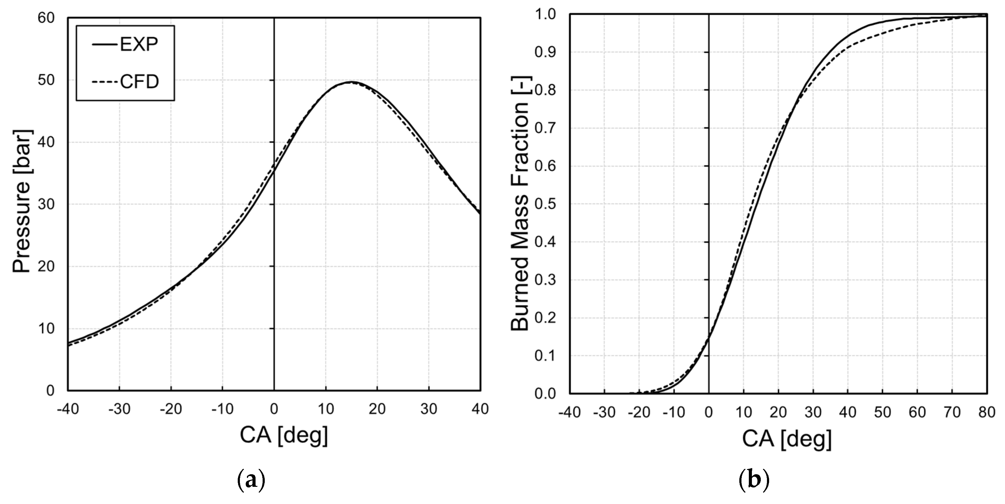
Figure 7 shows the trends of both the in-cylinder pressure and the burned mass fraction during the combustion phase at 4000 rpm. A very good accuracy was achieved during the whole process, with a slight overestimation of the in-cylinder pressure during the exhaust phase by the CFD, confirming the robustness of the numerical setup and the predictivity of the combustion model when changing the operating conditions.
3.2. Preliminary Pre-Chamber Analysis
After the calibration and validation of the combustion model, the very same numerical setup was employed in the numerical analysis of the pre-chamber-equipped engine.
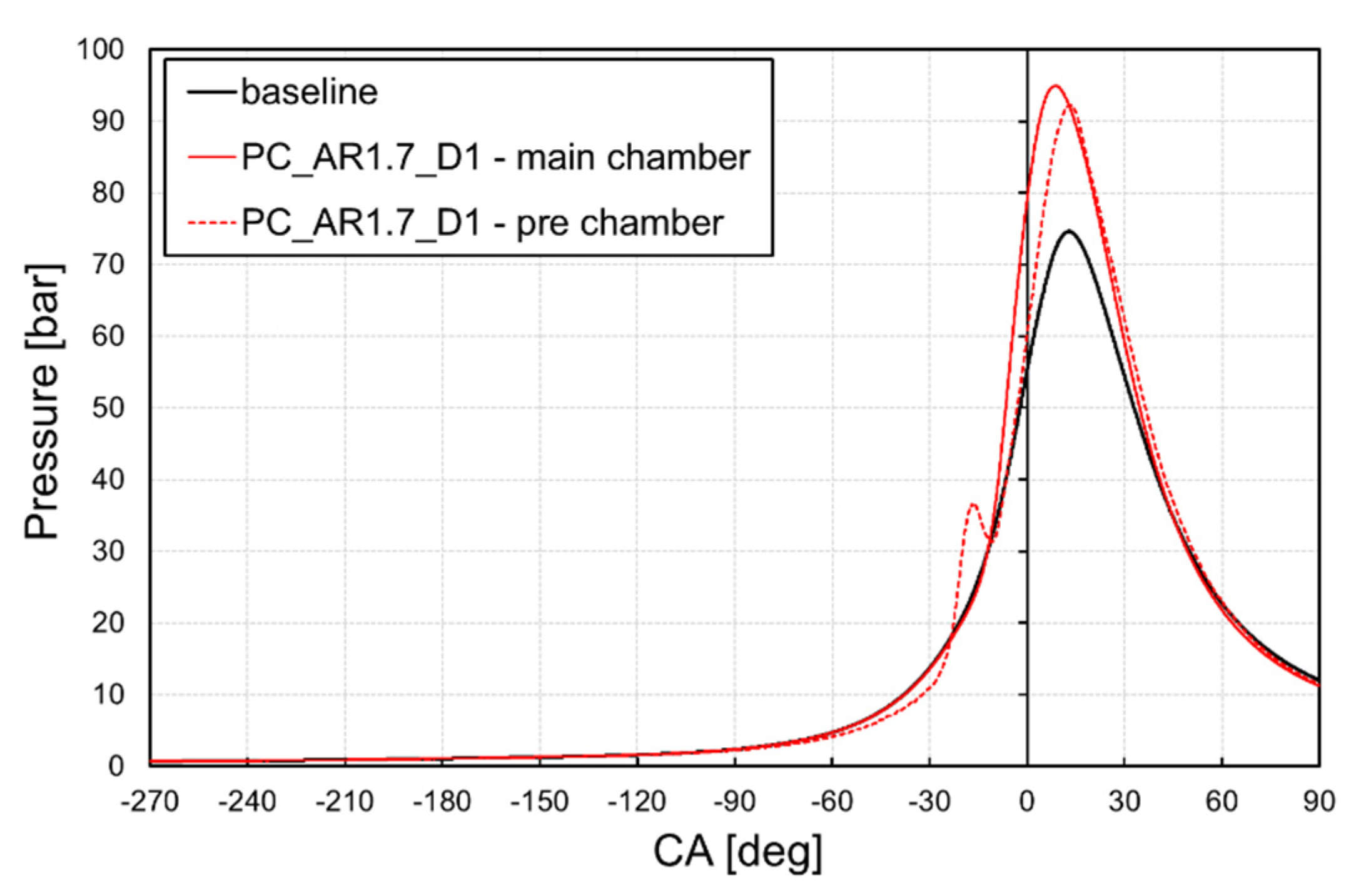
Figure 8 shows the comparison, in terms of pressure, between the baseline engine model and the one equipped with the passive pre-chamber PC_AR1.7_D1. In the case of the engine equipped with a pre-chamber, the dashed line represents the pressure inside the volume of the pre-chamber and the solid line represents the pressure in the main combustion chamber. It can be noted that the differences between the in-cylinder pressure values during the scavenging phase between the baseline engine and the pre-chamber engine are negligible. This suggests that the pre-chamber does not affect the pressure inside the main combustion chamber during the scavenging process. It also can be noted that a pressure drop between the main chamber and pre-chamber is established during the compression phase; this is due to the flow passing through the narrow orifices of the pre-chamber. At the end of the compression phase, the pressure difference between the main chamber and pre-chamber is roughly 1.5 bar.
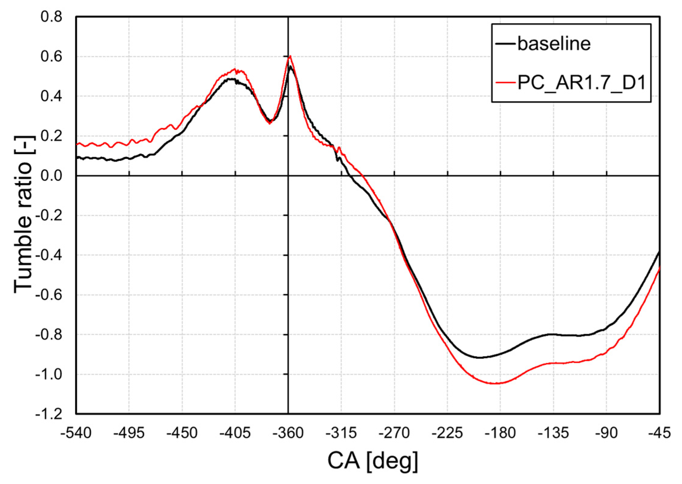
Figure 9 shows the evolution of the tumble ratio inside the cylinder during the scavenging phase, for the baseline and pre-chamber simulations. Minor differences between the two configurations can be noted during the exhaust and overlap phases. Conversely, when the intake valves are closing, tumble ratio is higher for PC_AR1.7_D1 than the baseline configuration. Therefore, while the pre-chamber does not affect the in-cylinder pressure, the turbulent structures coming from the pre-chamber enhance tumble motion.
Regarding the combustion phase, it is worth pointing out that the simulation with pre-chamber was first carried out with the same spark time of the baseline setup (i.e., 33° CA before the TDC) in order to directly evaluate the increase of the maximum in-cylinder pressure resulting from the faster combustion process. Therefore, such spark advance is optimized for the baseline configuration only. The simulation results of the pre-chamber engine with the optimized spark advance will be shown in the following sections.
From a perusal of
Figure 8, the phase in which the mixture ignites inside the pre-chamber and enters the main chamber in the form of hot flame jets is apparent. Indeed, two different peaks of pressure inside the pre-chamber can be observed: the first occurs when the fresh mixture is completely burned, and the flame is passing through the orifices; the second is due to the combustion inside the main chamber and the subsequent pressure rise inside the cylinder. Comparing the pressure curves, the engine with a pre-chamber is subjected to a very high pressure. Peak pressure for the pre-chamber configuration is roughly 20 bar higher than the baseline configuration and it occurs 5 CA degrees earlier. It is apparent that, when employing a pre-chamber to ignite the mixture inside the cylinder, a faster and more ideal combustion is attained.
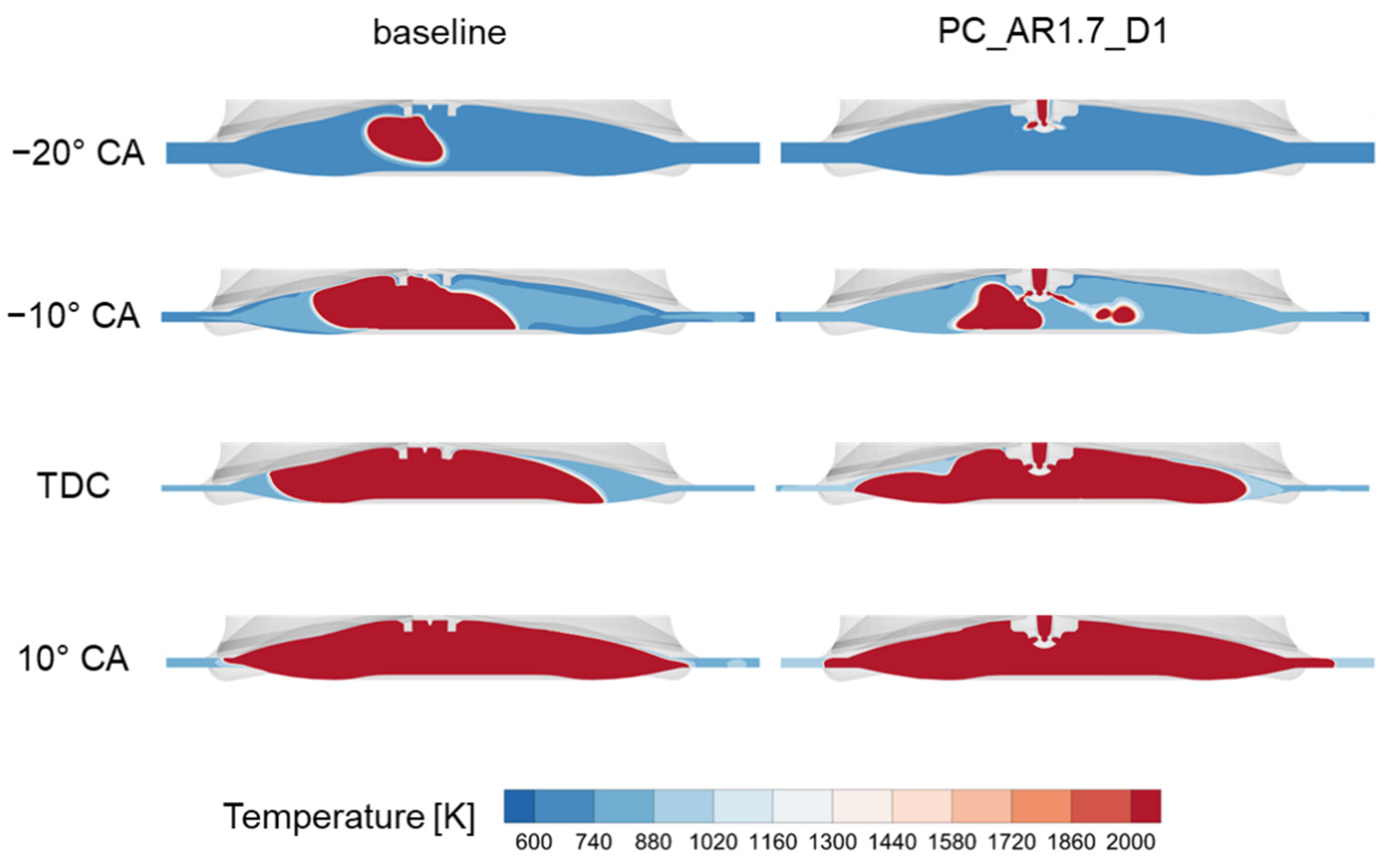
Figure 10 shows contours of in-cylinder temperature during combustion for the baseline and pre-chamber-equipped configurations, at different crank angle degrees. At 20 CA degrees before TDC, the hot jets from the pre-chamber enter the main chamber. At the same time, in the baseline configuration, combustion is still in its laminar phase and less than 10% of the fuel mass has burned. At 10 CA degrees before TDC, the flame jets impinge on the piston surface, igniting the fresh mixture in the main chamber. When the piston is at TDC, the flame front in PC_AR1.7_D1 has covered 2/3 of the combustion chamber and roughly the 50% of the fuel mass has burned. Eventually, the flame front propagates through the squish area faster than the baseline configuration, due to the hot jets-enhanced turbulent flame speed.
3.2.1. Analysis of Pre-Chamber Aspect Ratio
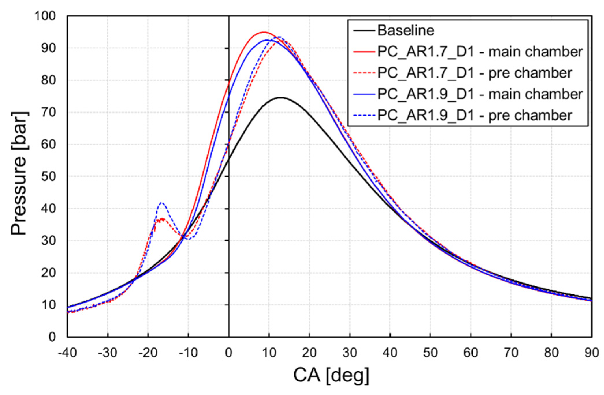
Figure 11 shows the comparison between PC_AR1.7_D1 and PC_AR1.9_D1 combustion process, in terms of pressure: solid lines refer to in-cylinder pressure, while dashed lines refer to the pressure inside the pre-chamber. The design of PC_AR1.9_D1 allows the trapping of more fuel with respect to PC_AR1.7_D1. As a consequence, peak pressure values inside the pre-chamber are higher for PC_AR1.9_D1 with respect to PC_AR1.7_D1. For the very same reason, peak pressure in the main chamber is roughly 2% lower for PC_AR1.9_D1 since less fuel mass remains in the cylinder. It is also apparent that combustion in the main chamber begins earlier for PC_AR1.7_D1, due to its lower aspect ratio. However, even if the hot jets from PC_AR1.9_D1 enter the pre-chamber later with respect to PC_AR1.7_D1, the combustion process is slightly faster, thanks to the higher pressure inside PC_AR1.9_D1 which enhances hot jets penetration.
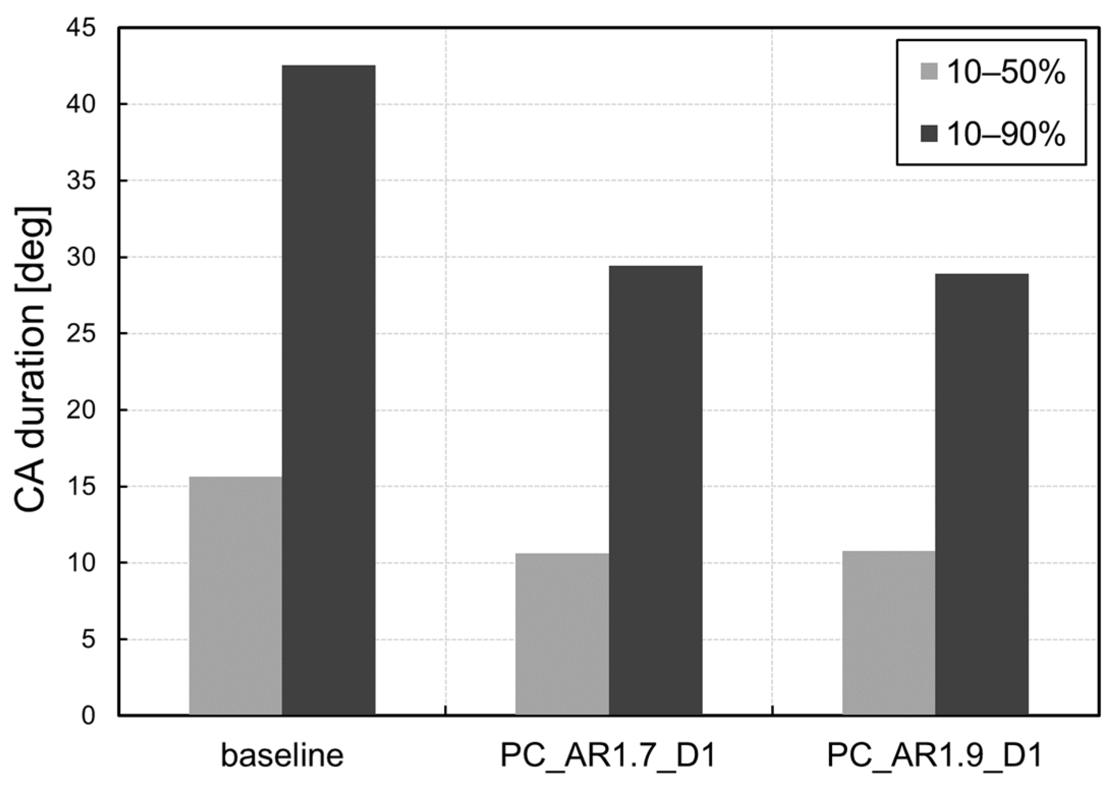
Figure 12 shows a quantification of the combustion duration inside the cylinder. Considering the 10–90% phase, the combustion of the PC_AR1.9_D1 case lasts roughly 1 CA less with respect to the PC_AR1.7_D1 one, while the 10–50% phase is almost equivalent. The pre-chamber with aspect ratio of 1.9 will be used for the subsequent analyses.
3.2.2. Analysis of Nozzle Diameter
Orifice (or nozzle) diameter is probably the most uncertain and, at the same time, pivotal parameter in passive pre-chamber design, as it affects pre-chamber scavenging: large orifices improve scavenging, since they generate lower pressure losses. Nozzle diameter also affects flame front propagation: large orifices may deteriorate the combustion process, because a large passage area would generate slow turbulent flame jets.
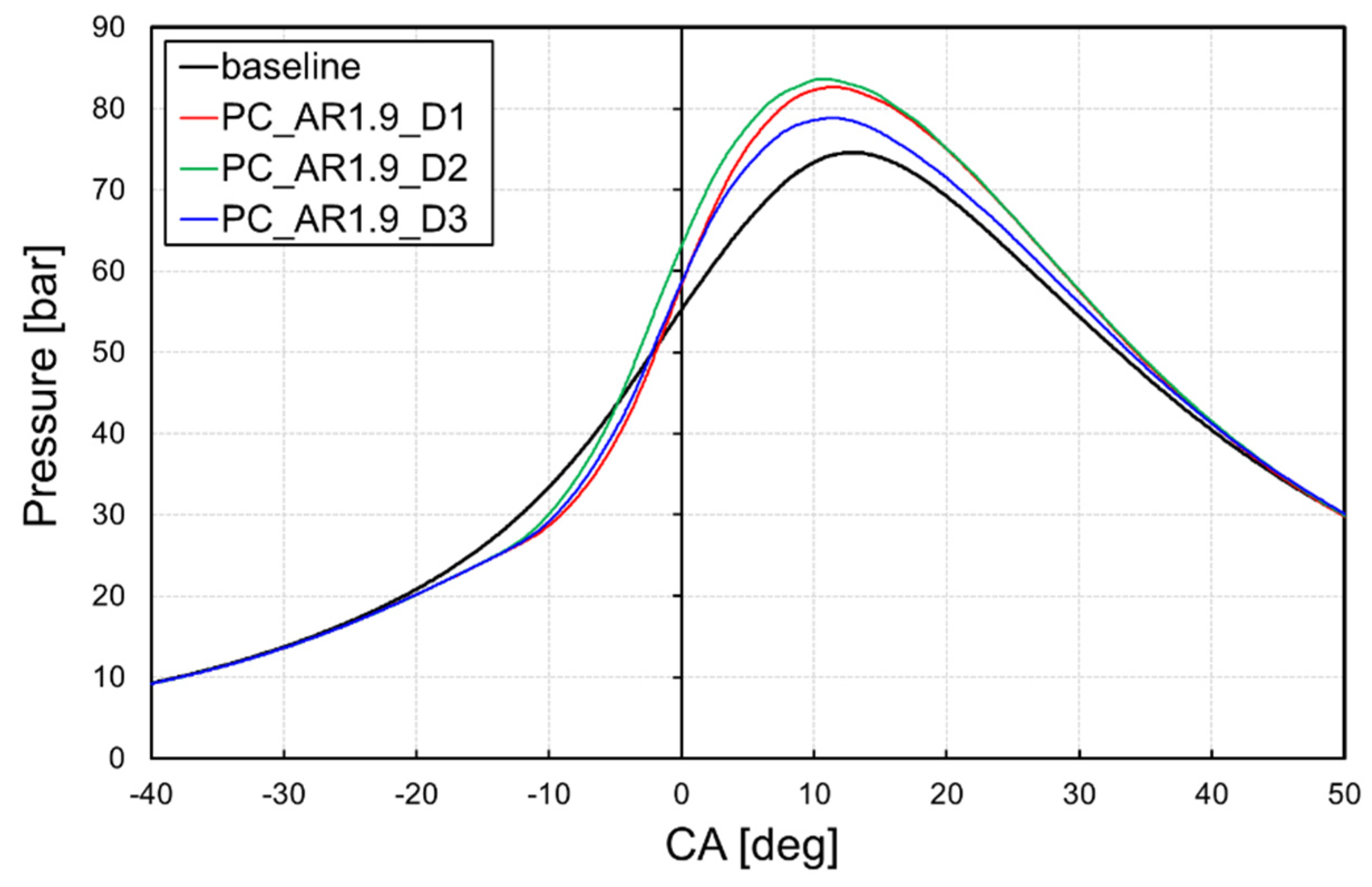
Figure 13 shows the evolution of the in-cylinder pressure during combustion: three different pre-chamber configurations are compared with the baseline engine setup. It is worth noting that the spark advance for the pre-chamber cases has been delayed to optimize the position of the in-cylinder peak pressure. Since the duration of the 10–50% was 5 CA degrees shorter, as previously shown in
Figure 12, the new spark advance was set to 28 CA before TDC. Notwithstanding the postponed ignition timing, a remarkable increase in peak pressure can still be observed when employing a pre-chamber. Specifically, PC_AR1.9_D2 grants the highest pressure inside the main chamber. Apparently, the diameter of its orifices grants the best trade-off between optimal scavenging and high turbulent flame jets momentum.
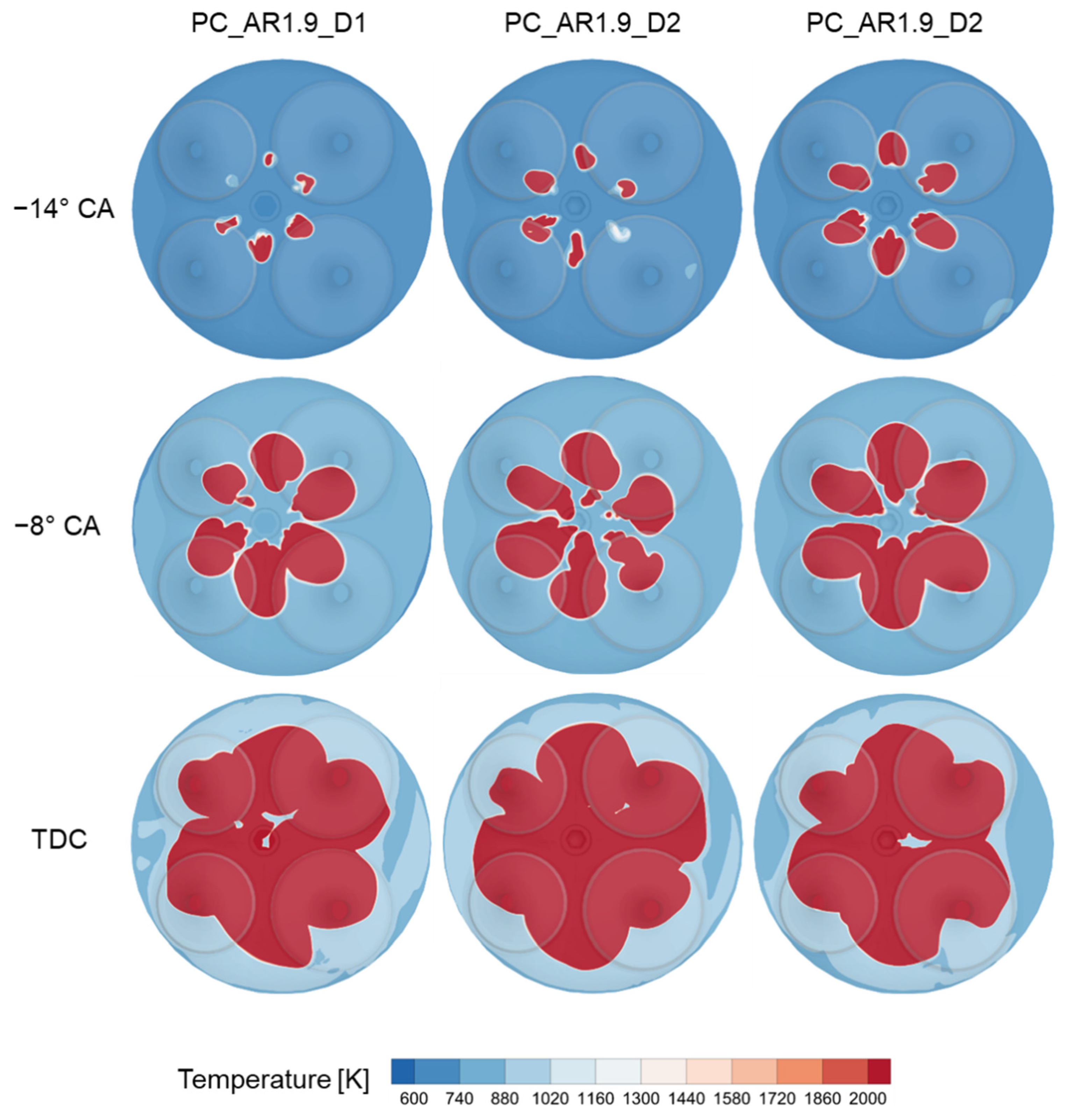
Figure 14 shows a top view of the evolution of the flame front during combustion. For PC_AR1.9_D3 case, all the flame jets have already exited the pre-chamber at 14 CA degrees before the TDC; at the same time, a portion of the flame front is still inside PC_AR1.9_D1 and PC_AR1.9_D2. Nevertheless, the flame jets coming from pre-chamber PC_AR1.9_D2 are able to penetrate the in-cylinder mixture with higher momentum, resulting in a faster combustion process after a slower ignition phase. Indeed, the extension of the flame front at the TDC is wider for the PC_AR1.9_D2 case.
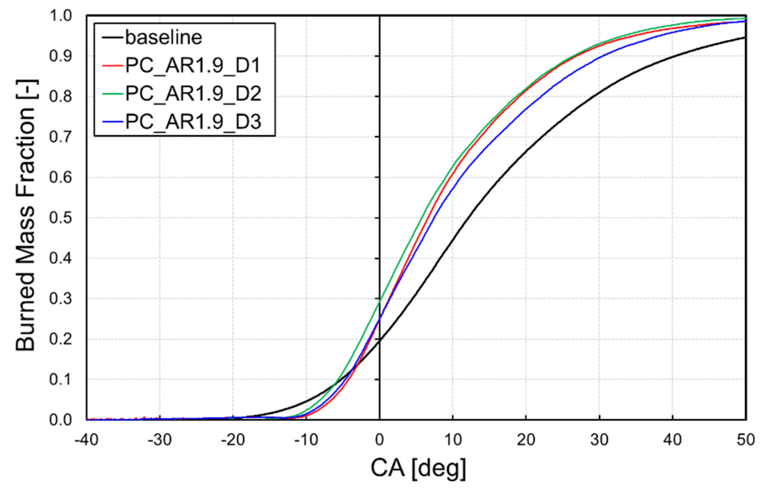
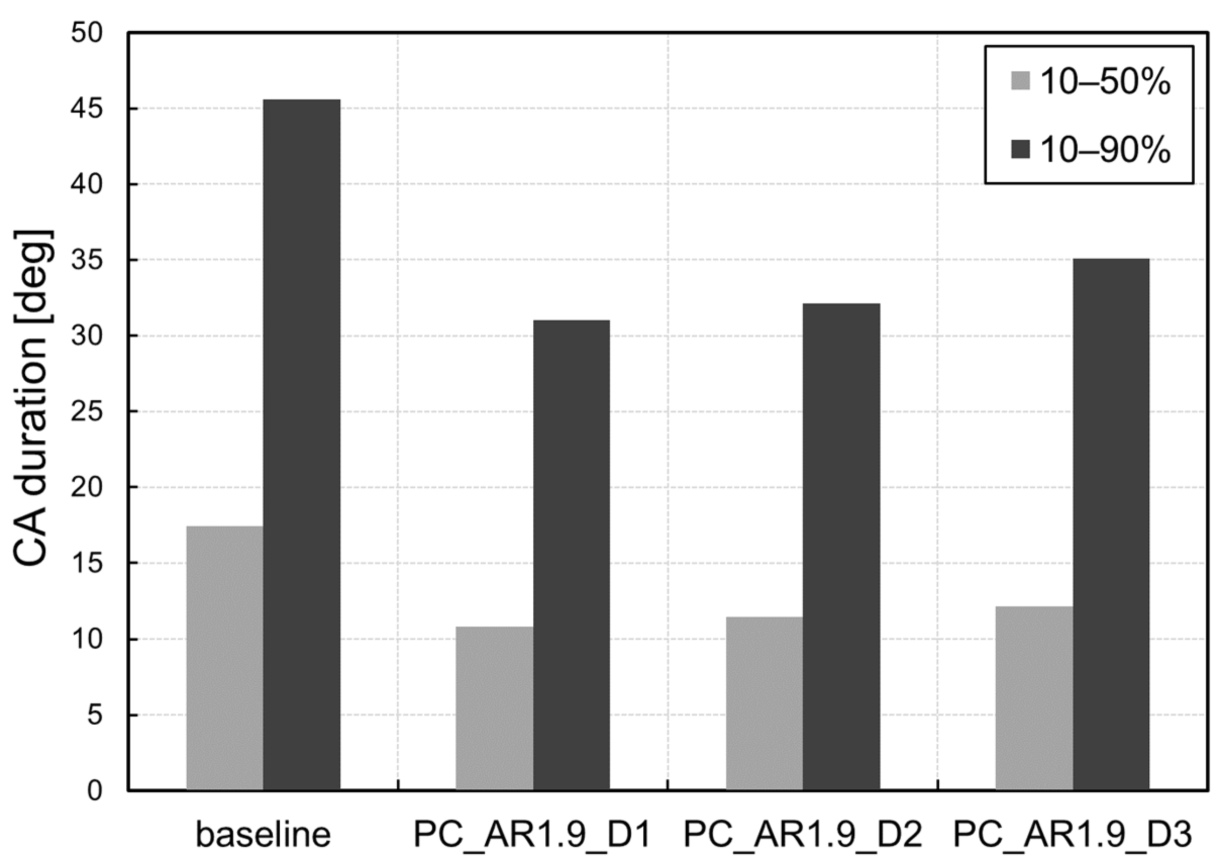
Figure 15 shows the evolution of burned fuel mass fraction inside the cylinder. The shortening of the combustion duration is clearly apparent: when 50% of fuel mass is burned in the baseline configuration, the amount of burned fuel is roughly 70% for the configurations with pre-chamber. The combustion duration was also quantified in terms of 10–50% and 10–90% of burned mass fraction.
Figure 16 shows that the fastest combustion is actually achieved with the PC_AR1.9_D1 geometry. On the one hand, the combustion start is slightly delayed due to the higher dilution of the fresh charge, due to the poorer scavenge caused by the smallest holes. On the other hand, when the jets are able to propagate inside the main chamber, the resulting flame front is characterized by a higher speed.
3.2.3. Analysis of Air-to-Fuel Ratio
According to the literature, turbulent jet ignition technology allows the extension the ignition limit of the air-fuel mixture towards leaner composition. To evaluate the potential of the pre-chamber under such conditions, a sensitivity analysis on the mixture air-fuel equivalence ratio was carried out for the baseline engine configuration and the three pre-chambers with the highest aspect ratio. Specifically, the composition of the fresh charge was varied by reducing the amount of premixed fuel.
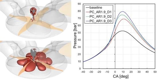
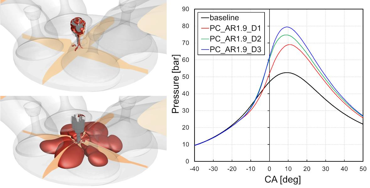
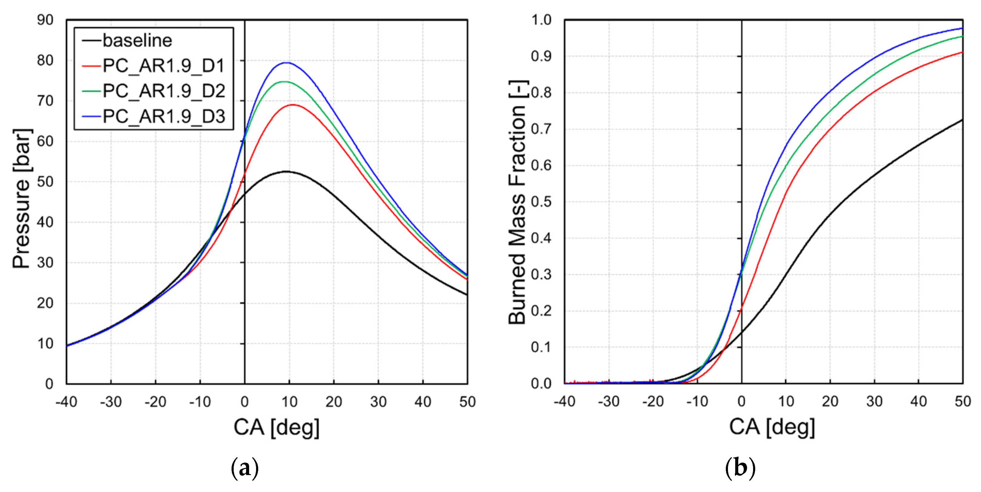
Figure 17a shows the evolution of in-cylinder pressure for an air-fuel equivalence ratio (λ) of 1.2. It is apparent that with a leaner mixture, larger orifices grant higher in-cylinder pressure with respect to the baseline configuration. Indeed, when operating with a lower amount of fuel, the enhanced trapping capability of the pre-chamber with large orifices becomes particularly beneficial. As a matter of fact, the pre-chamber with the smallest nozzles shows the worst performance. It is worth noting that, at the angular position of 50 CA degrees, the in-cylinder pressure for all pre-chambers’ cases is significantly higher than the baseline one, while in the former case of “standard” rich mixture such a difference was not observed. From the comparison of the burned mass fraction trends inside the cylinder (
Figure 17b) it is clear that the combustion is almost complete when adopting a pre-chamber, while in the baseline case the fuel burnt is only roughly 70%. This result implies that the increase in the flame front speed guaranteed by the jet ignition is more marked in lean conditions.
In particular, the PC_AR1.9_D3 geometry is able to guarantee a maximum pressure of roughly 80 bar, which is equivalent to the rich conditions, while the baseline engine suffers from a drop in the pressure of roughly 20 bar. Overall, it can be concluded that the combustion is greatly enhanced when employing a pre-chamber for the ignition of leaner mixtures and, when increasing the air-fuel equivalence ratio up to 1.2, the performance deterioration is only marginal for the pre-chamber cases, while it is significant for the baseline case.
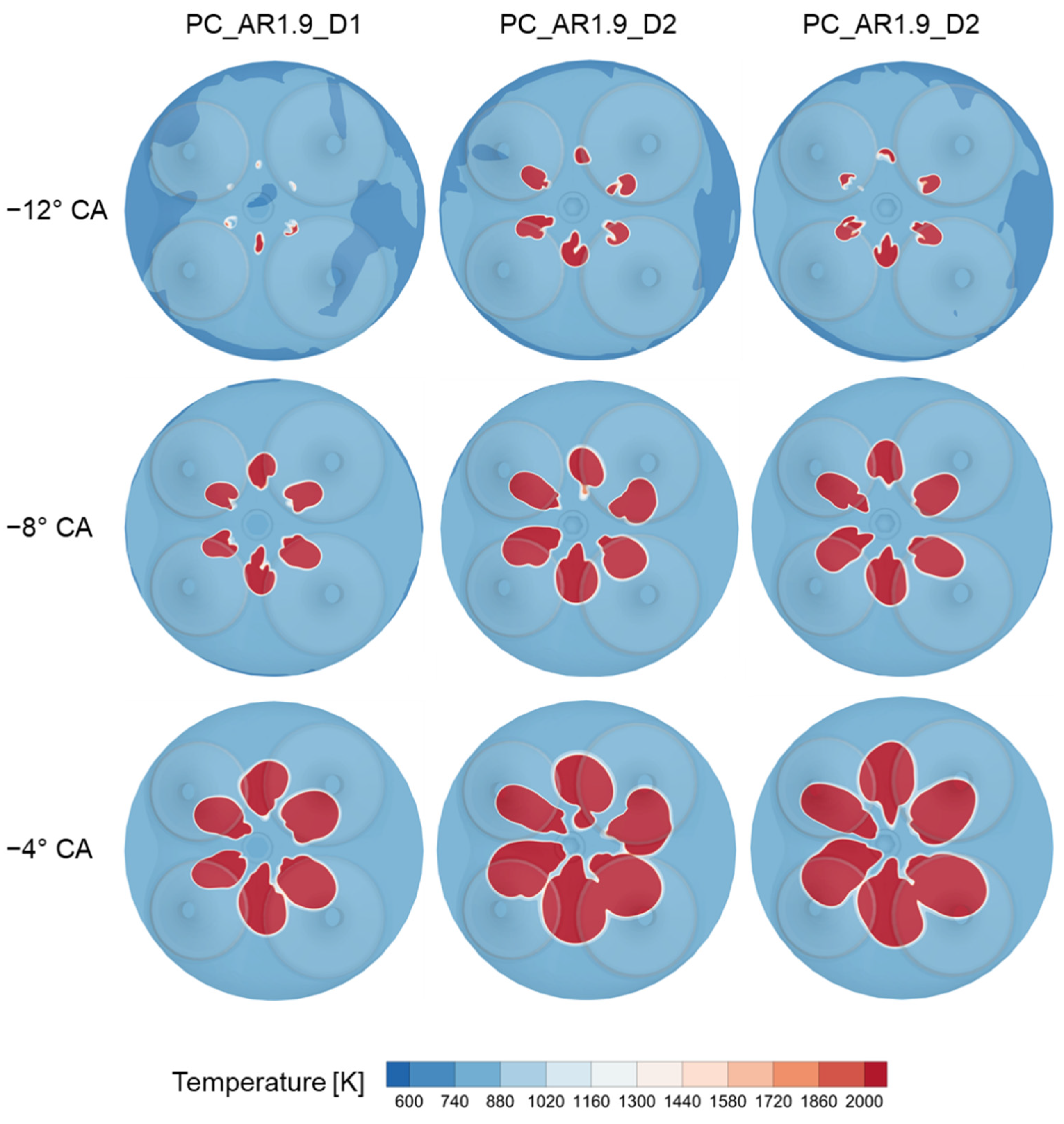
From
Figure 17b it is also apparent that ignition is more markedly delayed for PC_AR1.9_D1 with respect to the other two pre-chambers, as already observed in
Figure 15 for the design equivalence ratio. Indeed, the contour plots in
Figure 18 show that the turbulent flame jets of PC_AR1.9_D2 and PC_AR1.9_D3 enter the main chamber earlier with respect to PC_AR1.9_D1, resulting in a faster ignition phase. Before TDC, there are no major differences in terms flame front propagation between PC_AR1.9_D2 and PC_AR1.9_D3.
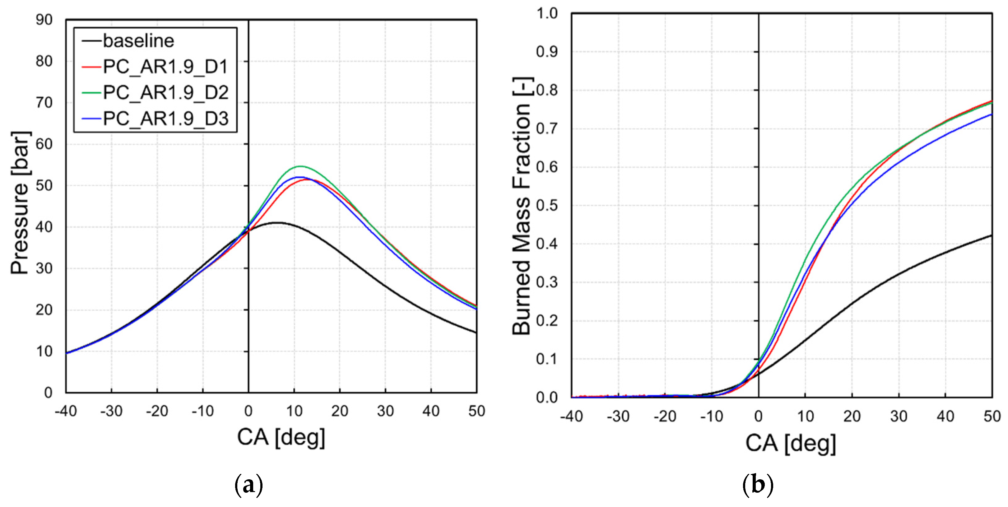
Figure 19a shows the evolution of in-cylinder pressure for an air-fuel equivalence ratio of 1.4. In this case, the performance variation between the different pre-chambers is less notable than the previous case, although they all show a strong reduction of the in-cylinder pressure with respect to the results with λ = 1.2.
Nevertheless, all the pre-chamber-equipped configurations show a remarkable improvement of the combustion process with respect to the baseline configuration, in terms of both in-cylinder pressure and burned mass fraction trends (
Figure 19b). It is worth pointing out that the pre-chamber PC_AR1.9_D2 produces the highest pressure inside the main chamber at the leanest tested conditions.
As a final remark, the reduction of fuel for the leanest tested condition of λ = 1.4 cannot be compensated only with the increased combustion efficiency to guarantee similar performance, as shown for the λ = 1.2 case. Therefore, a supercharging strategy should be evaluated in such conditions to increase the intake mass. Notwithstanding this, the results are useful to highlight the lean running capability and potential of the pre-chamber ignition.
4. Conclusions
In the present study, an accurate and predictive numerical setup for the 3D CFD simulation of the combustion process in SI engines was developed. The numerical setup was employed to assess the performance of the engine when equipped with different types of passive pre-chamber.
The test case of the present study is a Betamotor 430 cm3 4-stroke, four valves, PFI spark ignition engine. Being a PFI engine, the air/fuel mixture was considered homogeneous and the fuel injection was not modelled. CFD simulations were carried out using the commercial software CONVERGE CFD.
Firstly, unsteady RANS simulations of the engine in its baseline configuration (i.e., without pre-chamber) were carried out. A detailed chemistry model, specifically the SAGE combustion model, was employed for the simulation of the combustion process. The reaction mechanism used in this work involves 41 chemical species and 124 reactions. The combustion model was calibrated at maximum power conditions and validated against experimental data. Very good agreement was found in terms of in-cylinder pressure and burned mass fraction: the difference between CFD and experimental peak pressure values was lower than 1%.
After the model validation, four passive pre-chamber geometries, differing in terms of aspect ratio and orifices size, were analysed. Regardless of the pre-chamber configuration, a faster combustion process was always observed when employing a pre-chamber, with a significant improvement in terms of in-cylinder pressure and flame propagation speed.
The main finding of the study is that the orifice size has the most significant impact on the combustion evolution, while the pre-chamber aspect ratio has a secondary effect. Moreover, the effect of the orifices size on the combustion speed is not monotonic, since there is an optimum trade-off between acceleration of the flame front inside the orifices (smaller diameter) and energy of the jets (bigger diameter).
In more detail, three different orifices size were tested. The flame front propagation at the design value of the air-to-fuel ratio was enhanced by the hot flame jets, resulting in a 30% faster combustion process in the best case. It was found that the largest orifices generated low momentum hot flame jets. Indeed, when employing the pre-chamber with the largest nozzles, combustion was 20% slower with respect to the other pre-chambers, and the in-cylinder peak pressure was 5% lower.
Eventually, a sensitivity analysis to the mixture air-to-fuel ratio was carried out, in order to evaluate the advantages and capabilities of a pre-chamber system for lean running. The results showed an improvement in the combustion performance for every configuration. The hot flame jets from the pre-chamber are able to ignite the fresh charge inside the main chamber even at lean conditions, extending the flammable limit of the mixture while still guaranteeing a fast combustion process. In particular, with an air-to-fuel equivalence ratio equal to 1.2, the pressure peak inside the cylinder with pre-chamber was 42% higher than the one computed in the baseline configuration and the combustion duration was more than halved.
Thanks to the preliminary results achieved, the authors have manufactured two pre-chamber prototypes to be experimentally verified on the test engine. The original engine head needs to be modified in order to be equipped with the pre-chamber in the spark plug insertion hole. In the future, we plan to carry out an extensive experimental campaign to assess the combustion behaviour for the whole engine operating range, as the current study design is limited to the full power regime.
Author Contributions
Conceptualization, F.B., S.B., G.F., N.M. and M.D.L.; methodology, S.B. and F.B.; software, S.B.; validation, S.B.; formal analysis, S.B.; investigation, S.B.; data curation, S.B. and F.B.; writing—original draft preparation, S.B., F.B. and I.C.; writing—review and editing, F.B. and I.C.; supervision, G.F., N.M., M.D.L. and L.A.; project administration, G.F.; resources, G.F. All authors have read and agreed to the published version of the manuscript.
Funding
This research received no external funding.
Institutional Review Board Statement
Not applicable.
Informed Consent Statement
Not applicable.
Data Availability Statement
Not applicable.
Conflicts of Interest
The authors declare no conflict of interest.
Abbreviations
| CA | Crank Angles Degrees |
| AMR | Adaptive Mesh Refinement |
| AR | Aspect Ratio |
| BSFC | Brake Specific Fuel Consumption |
| CFD | Computational Fluid Dynamics |
| CO | Carbon Oxide |
| ICE | Internal Combustion Engine |
| LTC | Low Temperature Combustion |
| NOX | Nitric Oxides |
| PFI | Port Fuel Injection |
| PM | Particulate Matter |
| RANS | Reynolds-Averaged Navier-Stokes |
| SI | Spark Ignition |
| STL | Stereo Lithography |
| TDC | Top Dead Center |
| TJI | Turbulent Jet Ignition |
| TKE | Turbulence Kinetic Energy |
| UDF | User-Defined Function |
References
- Agarwal, A.K.; Singh, A.P.; Maurya, R.K. Evolution, Challenges and Path Forward for Low Temperature Combustion Engines. Prog. Energy Combust. Sci. 2017, 61, 1–56. [Google Scholar] [CrossRef]
- Adams, T.G. Torch Ignition for Combustion Control of Lean Mixtures; SAE Technical Paper; SAE International: Warrendale, PA, USA, 1979. [Google Scholar] [CrossRef]
- Mavinahally, N.S.; Assanis, D.N.; Govinda Mallan, K.R.; Gopalakrishnan, K.V. Torch Ignition: Ideal for Lean Burn Premixed-Charge Engines. J. Eng. Gas. Turbines Power 1994, 116, 793–798. [Google Scholar] [CrossRef]
- Hayashi, A.K.; Matsuura, K.; Baba, S. Performance of a Flame Jet Ignition System in a Two-Stroke Engine; SAE Technical Paper; SAE International: Warrendale, PA, USA, 2000. [Google Scholar] [CrossRef]
- Gomes, J.R.C.; Valle, R.M.; Pujatti, F.J.P.; Pereira, J.P. Torch Ignition System Analysis in an Spark Ignition Engine; SAE Technical Paper; SAE International: Warrendale, PA, USA, 2005. [Google Scholar] [CrossRef]
- Attard, W.P.; Blaxill, H.; Anderson, E.K.; Litke, P. Knock Limit Extension with a Gasoline Fueled Pre-Chamber Jet Igniter in a Modern Vehicle Powertrain. SAE Int. J. Engines 2012, 5, 1201–1215. [Google Scholar] [CrossRef]
- Gentz, G.; Thelen, B.; Gholamisheeri, M.; Litke, P.; Brown, A.; Hoke, J.; Toulson, E. A Study of the Influence of Orifice Diameter on a Turbulent Jet Ignition System through Combustion Visualization and Performance Characterization in a Rapid Compression Machine. Appl. Therm. Eng. 2015, 81, 399–411. [Google Scholar] [CrossRef]
- Stadler, A.; Wessoly, M.; Blochum, S.; Härtl, M.; Wachtmeister, G. Gasoline Fueled Pre-Chamber Ignition System for a Light-Duty Passenger Car Engine with Extended Lean Limit. SAE Int. J. Engines 2019, 12, 323–340. [Google Scholar] [CrossRef]
- Röthlisberger, R.; Favrat, D. Investigation of the Prechamber Geometrical Configuration of a Natural Gas Spark Ignition Engine for Cogeneration: Part. I, Numerical Simulation. Int. J. Therm. Sci. 2003, 42, 223–237. [Google Scholar] [CrossRef]
- Wolff, D.; Tamura, M.; Tai, H.; Sakurai, T. Looking into the Prechamber of a Lean-Burn Gas Engine. JSME Int. J. Ser. B 1997, 40, 320–327. [Google Scholar] [CrossRef] [Green Version]
- Attard, W.P.; Toulson, E.; Huisjen, A.; Chen, X.; Zhu, G.; Schock, H. Spark Ignition and Pre-Chamber Turbulent Jet Ignition Combustion Visualization; SAE Technical Paper; SAE International: Warrendale, PA, USA, 2012. [Google Scholar] [CrossRef] [Green Version]
- Fu, L.; Ishima, T.; Long, W.; Tian, J. Research on the Ignition-Chamber GDI Engine Combustion System. JTST 2009, 4, 53–62. [Google Scholar] [CrossRef] [Green Version]
- Shapiro, E.; Tiney, N.; Kyrtatos, P.; Kotzagianni, M.; Bolla, M.; Boulouchos, K.; Tallu, G.; Lucas, G.; Weissner, M. Experimental and Numerical Analysis of Pre-Chamber Combustion Systems for Lean Burn Gas Engines; SAE Technical Paper; SAE International: Warrendale, PA, USA, 2019. [Google Scholar] [CrossRef] [Green Version]
- Yamanaka, K.; Shiraga, Y.; Nakai, S. Development of Pre-Chamber Sparkplug for Gas Engine; SAE International: Warrendale, PA, USA, 2011. [Google Scholar] [CrossRef]
- Bosi, L.; Ciampolini, M.; Romani, L.; Balduzzi, F.; Ferrara, G. Experimental Analysis on the Effects of Passive Prechambers on a Small 2-Stroke Low-Pressure Direct Injection (LPDI) Engine; SAE International: Warrendale, PA, USA, 2020. [Google Scholar] [CrossRef]
- Bosi, L.; Ciampolini, M.; Raspanti, S.; Romani, L.; Ferrara, G. Jet Ignition in Small Two-Stroke Engines: An Experimental Survey on Benefits and Challenges. E3S Web Conf. 2021, 312, 07012. [Google Scholar] [CrossRef]
- Ciampolini, M.; Bigalli, S.; Balduzzi, F.; Bianchini, A.; Romani, L.; Ferrara, G. CFD Analysis of the Fuel–Air Mixture Formation Process in Passive Prechambers for Use in a High-Pressure Direct Injection (HPDI) Two-Stroke Engine. Energies 2020, 13, 2846. [Google Scholar] [CrossRef]
- Radicchi, F.; Braga, R.M.; Coelho, R.A.; Costa, R.B.R.; Valle, R.M. Numerical Analysis of a Torch-Ignition System for an Internal Combustion Engine. AMM 2015, 798, 234–238. [Google Scholar] [CrossRef]
- Millo, F.; Rolando, L.; Piano, A.; Sementa, P.; Catapano, F.; Di Iorio, S.; Bianco, A. Experimental and Numerical Investigation of a Passive Pre-Chamber Jet Ignition Single-Cylinder Engine; SAE International: Warrendale, PA, USA, 2021. [Google Scholar] [CrossRef]
- Badra, J.; Khaled, F.; Sim, J.; Pei, Y.; Viollet, Y.; Pal, P.; Futterer, C.; Brenner, M.; Som, S.; Farooq, A.; et al. Combustion System Optimization of a Light-Duty GCI Engine Using CFD and Machine Learning; SAE International: Warrendale, PA, USA, 2020. [Google Scholar] [CrossRef]
- Battistoni, M.; Mariani, F.; Risi, F.; Poggiani, C. Combustion CFD Modeling of a Spark Ignited Optical Access Engine Fueled with Gasoline and Ethanol. Energy Procedia 2015, 82, 424–431. [Google Scholar] [CrossRef] [Green Version]
- Thelen, B.C.; Toulson, E. A Computational Study on the Effect of the Orifice Size on the Performance of a Turbulent Jet Ignition System. Proc. Inst. Mech. Eng. Part. D J. Automob. Eng. 2017, 231, 536–554. [Google Scholar] [CrossRef]
- Ferrara, G.; Balduzzi, F.; Vichi, G. An Innovative Solution for Two-Stroke Engines to Reduce the Short-Circuit Effects; SAE International: Warrendale, PA, USA, 2012. [Google Scholar] [CrossRef]
- Balduzzi, F.; Vichi, G.; Romani, L.; Ferrara, G.; Trassi, P.; Fiaschi, J.; Tozzi, F. Development of a Low Pressure Direct Injection System for a Small 2S Engine. Part I—CFD Analysis of the Injection Process. SAE Int. J. Engines 2015, 8, 1885–1897. [Google Scholar] [CrossRef]
- Balduzzi, F.; Vichi, G.; Romani, L.; Ferrara, G. CFD Analysis of the Effect of the Injection Pressure on a Small 2S LPDI Engine; SAE International: Warrendale, PA, USA, 2015. [Google Scholar]
Figure 1.
Comparison between 1D GT-Power results and pressure measurements (a) intake duct; (b) exhaust duct.
Figure 1.
Comparison between 1D GT-Power results and pressure measurements (a) intake duct; (b) exhaust duct.
Figure 2.
Mesh sensitivity results (a) in-cylinder pressure; (b) in-cylinder tumble ratio.
Figure 2.
Mesh sensitivity results (a) in-cylinder pressure; (b) in-cylinder tumble ratio.
Figure 3.
Detail of grid refinement in the spark plug region.
Figure 3.
Detail of grid refinement in the spark plug region.
Figure 4.
Schematic of the main geometrical features of the pre-chamber.
Figure 4.
Schematic of the main geometrical features of the pre-chamber.
Figure 5.
Results of the numerical model calibration: comparison between simulated and measured in-cylinder pressure in full power conditions.
Figure 5.
Results of the numerical model calibration: comparison between simulated and measured in-cylinder pressure in full power conditions.
Figure 6.
Results of the numerical model calibration: comparison between simulated and measured S-curve in full power conditions.
Figure 6.
Results of the numerical model calibration: comparison between simulated and measured S-curve in full power conditions.
Figure 7.
Validation of the numerical model at 4000 rpm: comparison between simulated and measured (a) in-cylinder pressure, (b) burned mass fraction.
Figure 7.
Validation of the numerical model at 4000 rpm: comparison between simulated and measured (a) in-cylinder pressure, (b) burned mass fraction.
Figure 8.
Comparison between simulated pressure traces during compression and combustion phases (dashed line: pre-chamber pressure, solid line: main combustion chamber pressure).
Figure 8.
Comparison between simulated pressure traces during compression and combustion phases (dashed line: pre-chamber pressure, solid line: main combustion chamber pressure).
Figure 9.
Comparison between simulated tumble ratio trends during exhaust, intake, and compression phases.
Figure 9.
Comparison between simulated tumble ratio trends during exhaust, intake, and compression phases.
Figure 10.
Flame front propagation: comparison between standard engine and pre-chamber engine.
Figure 10.
Flame front propagation: comparison between standard engine and pre-chamber engine.
Figure 11.
Simulated pressure traces during combustion (dashed line: pre-chamber pressure, solid line: main combustion chamber pressure): comparison between standard engine and engine equipped with two pre-chambers with different aspect ratio.
Figure 11.
Simulated pressure traces during combustion (dashed line: pre-chamber pressure, solid line: main combustion chamber pressure): comparison between standard engine and engine equipped with two pre-chambers with different aspect ratio.
Figure 12.
Duration of combustion phase: comparison between standard engine and engine equipped with two pre-chambers with different aspect ratio.
Figure 12.
Duration of combustion phase: comparison between standard engine and engine equipped with two pre-chambers with different aspect ratio.
Figure 13.
Influence of the orifice diameter on the in-cylinder pressure trend during combustion.
Figure 13.
Influence of the orifice diameter on the in-cylinder pressure trend during combustion.
Figure 14.
Influence of the orifice diameter on flame front propagation.
Figure 14.
Influence of the orifice diameter on flame front propagation.
Figure 15.
Influence of the orifice diameter on the burned mass fraction evolution.
Figure 15.
Influence of the orifice diameter on the burned mass fraction evolution.
Figure 16.
Influence of the orifice diameter on the duration of combustion phase.
Figure 16.
Influence of the orifice diameter on the duration of combustion phase.
Figure 17.
Influence of the orifice diameter on the (a) in-cylinder pressure trend and (b) burned mass fraction evolution with air-fuel equivalence ratio of 1.2.
Figure 17.
Influence of the orifice diameter on the (a) in-cylinder pressure trend and (b) burned mass fraction evolution with air-fuel equivalence ratio of 1.2.
Figure 18.
Influence of the orifice diameter on flame front propagation with air-fuel equivalence ratio of 1.2.
Figure 18.
Influence of the orifice diameter on flame front propagation with air-fuel equivalence ratio of 1.2.
Figure 19.
Influence of the orifice diameter on the (a) in-cylinder pressure trend and (b) burned mass fraction evolution with air-fuel equivalence ratio of 1.4.
Figure 19.
Influence of the orifice diameter on the (a) in-cylinder pressure trend and (b) burned mass fraction evolution with air-fuel equivalence ratio of 1.4.
Table 1.
Main characteristics of the Betamotor 430 cm3 engine.
Table 1.
Main characteristics of the Betamotor 430 cm3 engine.
| Engine Type | 4-Stroke, PFI, Gasoline |
|---|
| Number of valves | 4 |
| Displacement | 430.90 cm3 |
| Bore | 95 mm |
| Stroke | 60.80 mm |
| Connecting rod | 106 mm |
| Compression ratio | 12 |
Table 2.
Main mesh properties for grid independency analysis.
Table 2.
Main mesh properties for grid independency analysis.
| Mesh Type | Coarse | Medium | Fine |
|---|
| Base grid size [m] | 5 × 10⁻³ | 4 × 10⁻³ | 4 × 10⁻³ |
| AMR scale based on velocity | 2 | 2 | 3 |
Table 3.
Mesh properties for the selected computational grid.
Table 3.
Mesh properties for the selected computational grid.
| Mesh Name | Fine |
|---|
| Base grid size [m] | 4.000 × 10⁻³ |
| Cylinder element size [m] | 0.500 × 10⁻³ |
| Spark plug 1 element size [m] | 0.250 × 10⁻³ |
| Spark plug 2 element size [m] | 0.125 × 10⁻³ |
| AMR based on velocity element size [m] | 0.500 × 10⁻³ |
| AMR based on temperature element size [m] | 0.125 × 10⁻³ |
| Number of elements @TDC | 4 M |
| Max no. elements in the combustion chamber (@14 °CA) | 5 M |
Table 4.
Geometrical configurations of simulated pre-chambers.
Table 4.
Geometrical configurations of simulated pre-chambers.
| Prechamber Property | Value |
|---|
| name | PC_AR1.7_D1 | PC_AR1.9_D1 | PC_AR1.9_D2 | PC_AR1.9_D3 |
| aspect ratio | 1.7 | 1.9 | 1.9 | 1.9 |
| nozzles diameter | d0 | d0 | 1.1 × d0 | 1.2 × d0 |
Table 5.
Numerical test plan.
Table 5.
Numerical test plan.
| Configuration | Baseline | PC_AR1.7_D1 | PC_AR1.9_D1 | PC_AR1.9_D2 | PC_AR1.9_D3 |
|---|
| A/F | 1 | x | x | x | x | x |
| 1.2 | x | | x | x | x |
| 1.4 | x | | x | x | x |
| Publisher’s Note: MDPI stays neutral with regard to jurisdictional claims in published maps and institutional affiliations. |
© 2022 by the authors. Licensee MDPI, Basel, Switzerland. This article is an open access article distributed under the terms and conditions of the Creative Commons Attribution (CC BY) license (https://creativecommons.org/licenses/by/4.0/).


 ,
, 


