
Multiphysics Design of an Automotive Regenerative Eddy Current Damper


1
Department of Industrial Engineering, University of Rome “Tor Vergata”, 00133 Rome, Italy
2
Department of Applied Science and Technology, Politecnico di Torino, 10129 Torino, Italy
3
AKKA Belgium, Avenue Jules Bordet 168, 1140 Evere, Belgium
*
Authors to whom correspondence should be addressed.
Energies 2022, 15(14), 5044; https://0-doi-org.brum.beds.ac.uk/10.3390/en15145044
Submission received: 14 May 2022
/
Revised: 28 June 2022
/
Accepted: 9 July 2022
/
Published: 11 July 2022
(This article belongs to the Special Issue Simulation and Optimization of Vehicle Dynamics System)
Abstract
:This research presents a finite element multi-physics design methodology that can be used to develop and optimise the inherent functions and geometry of an innovative regenerative eddy current (REC) damper for the suspension of B class vehicles. This methodology was inspired by a previous work which has been applied successfully for the development of an eddy current (EC) damper used for the same type of applications. It is based on a multifield finite element coupled model that can be used to fulfil the electromagnetic, thermal, and fluid dynamic field properties and boundary conditions of a REC damper, as well as its non-linear material properties and boundary conditions, while also analysing its damping performance. The proposed REC damper features a variable fail-safe damping force, while electric power is advantageously regenerated at high suspension frequencies. Its damping performance has been benchmarked against that of a regular hydraulic shock absorber (selected as a reference) by analysing the dynamic behaviour of both systems using a quarter car suspension model. The results are expressed in terms of damping force, harvested power, thermal field, comfort and handling, with reference to ISO-class roads. The optimisation analysis of the REC damper has suggested useful guidelines for the harmonisation of damping and regenerative power performances during service operation at different piston speeds.
1. Introduction
The main purpose of vehicle suspension systems is to ensure comfort, handling and safety. The former is accomplished by isolating the vehicle body from road irregularities, while the latter requires continuous tyre-road contact [1]. These two conflicting aims suggest that stiffer suspensions prevent wheel hopping, while softer suspensions reduce the vibrations of the vehicle body. Semi-active and fully active suspensions have been developed over the last few decades to mitigate such conflicting aims. A passive suspension includes a mechanical spring and a viscous damper, which are connected in parallel. Such a suspension is widely used in vehicles to dissipate mechanical vibrations into heat.
The damper is generally the most complex device in the suspension system as it exhibits non-linear behaviour, which is influenced by temperature, the valve configuration, the tube design, and friction forces.
Fukushima et al. [2] theoretically analysed the role of the damper force on handling, riding comfort, ride harshness, and road noise using a multibody analysis, and suggested that comfort damping should be smaller than the force required for handling and safety, and that large stroke damping should be below 0.2 m/s.
In addition, car manufacturers also have to deal with national and international directives on fuel consumption and environmental pollution, as well as having limited access to raw materials. The latter issue, for instance, is very stringent concerning the production of batteries. Thus, strategies and technologies aimed at using fuel more efficiently, or recovering energy that would otherwise be wasted in vehicles, have become a current topic of strategic research.
Zhang et al. [3] showed that a four-damper passenger car, travelling at 100 km/h speed, can dissipate heat of up to 200 W, on ISO C class [4] roads. This suggests the need for the design of a suitable conversion unit that could efficiently convert any recoverable mechanical energy, such as that available from mechanical vibrations, into electric energy. A green technology, based on a fluid-free damper, is highly desirable, for example, in the case of an integral device that combines both variable damping and regenerative functions.
Rotary electro-mechanical and electro-hydraulic regenerative devices fall into such a category.
Regenerative rotary dampers can provide high-energy density, but they require additional complex systems to turn linear motion into rotary motion. For this purpose, a rack and pinion mechanism was used in a regenerative rotary damper [5]. After conducting experimental tests on this device, it was reported that an average generation power of 7.2 W could be achieved with an overall efficiency of 44%. However, the device suffered from certain inherent shortcomings, such as backlash events upon reversed motion, as well as gear friction. Li et al. [6] introduced a mechanical motion rectifier to prevent backlash and inertial effects.
Amati et al. [7] designed an alternate regenerative concept based on a ball-screw, transmission-based, rotary electromechanical passive and/or semi-active damper. The proof-of-concept prototype was tested on a laboratory test rig, and its damping performance was successfully compared with that of an analytical model [8]. Very high damping coefficients were observed at low frequencies (2.49 and 12.9 kNs/m) under open and short circuit conditions, respectively. The outer diameter and the final mass of their damper were 114 mm and 9.7 kg, respectively. The ball-screw technology was also employed in ref. [9] to turn the linear motion of a generator into rotational motion, while a one-way clutch was used for the one-direction of the rotary generator.
In 2016, Audi AG presented a new concept of electromechanical suspension, that is, eROT, which is based on an electric machine that uses a gearbox and a lever arm for transmission [10]. In such a layout, a vertical, telescopic, hydraulic damper is replaced by a horizontal tubular machine for space saving. The vertical oscillation of the rear wheel is transformed into rotational motion that is then sent to the electric machine by the transmission system. The damper acts as an active system, while configurable software is used to control its characteristics. The initial tests on both freshly paved and rough German roads showed 3 to 613 W of harvested power, thus corresponding to 3 g/km CO2.
An in-depth modelling-based design methodology for a rotary electromagnetic mechanical transmission suspension system is presented in [11]. The authors investigated the role of the gear transmission ratio on the performance and size of the electric machine. Experiments carried out on the realized prototype have shown that the regenerative-damper device can produce very high damping (11.32 kNs/m) for only 3.51 kg of weight, excluding the linear-to-rotary transmission device. The authors also stated that the acoustic performance of their damper was within the regulation limits and had a maximum conversion efficiency of 59.86%.
Electromechanical suspension systems exhibit relatively simple technological features and high motion/energy conversion ability. However, they suffer from several limitations (e.g., backlash, friction, noise, inertia, and lack of durability), and their inherent technology remains under continual development.
It is the hydraulic fluid in electrohydraulic dampers that transmits the linear excitation of the wheel to a rotary electric machine, while check valves control the unidirectionality of the rotational motion.
An interesting energy-harvesting shock absorber, which features a combination of energy harvesting with shock absorption, was proposed by Li et al. [12]. An integrated hydraulic rectifier prevents frequent reversing. Later, Galluzzi et al. [13] analysed how such a motion rectifier influences the overall performance of the suspension. Prior results on damping forces and power regeneration were supported by enhanced computer models and robust prototype validation testing in [14]. The sensitivity of each component involved in the design was inspected, in terms of conversion efficiency of the machine. Parallel studies were conducted on a hydraulic motion rectifier and a rotary electric machine and the results are reported in [15,16].
Linear, electromagnetic suspension shock absorbers directly transform the vertical oscillations of the wheel into electric currents in the conductors, without any transmission mechanism. As a result, this technology is greatly simplified, but the relevant geometry of any existing suspension devices is retained. Any limitation associated with the transmission mechanisms and inherent negative effects on the performance indices can, therefore, be eliminated. Moreover, this technology can be totally free of polluting hydraulic fluid. Its performance can easily be controlled, or be more predictable, because there are no mechanical connections or transmission mechanisms, with the only drawback being, perhaps, its low power density.
Karnopp et al. [17] pioneered research that addressed the use of a permanent-magnet linear motor with variable resistors in an attempt to substitute conventional hydraulic dampers. Ebrahimi et al. [18] developed an eddy current passive damper, which consists of PMs, an IP magnetic piston and a surrounding conductive tube, for automotive applications. Zuo et al. [19] later investigated a similar assembly for pure regenerative functions. They developed a design methodology and conducted FE simulations to optimise the performances of the device, in terms of electric output, in the case of a halved prototype. Laboratory tests on such a prototype revealed an average power output of 1.29 W at 0.25 m/s rms velocity. The importance of a high permeability material for the outer cylinder was also noted.
Ribeiro et al. [20] designed a hybrid (electromagnetic–hydraulic) regenerative damper. Its electromagnetic configuration shared some similarities with that reported in ref. [19]. The overall damping of the device was controlled by the load resistance. The device performances were accounted for using a lumped magnetic circuit model combined with an FE model. The results showed that the damping was at a maximum in a short circuit, while the maximum regenerated power was attained when the load resistance and the internal resistance of the coils were identical. As a follow up of this study, the authors manufactured a hybrid fluid, an electromagnetic regenerative damper prototype consisting of an outer rectangular 76.2 mm wide casing [21], and its full performances were experimentally analysed as a function of the load resistance. The resulting damping coefficients ranged between 1302 and 1540 Ns/m and were composed of a constant (1302 Ns/m) oil damping and variable electromagnetic damping (up to 238 Ns/m). The contribution of circuit inductance to the performance was found to be significant. This suggested it was of paramount importance to consider circuit inductance in the calculations, starting from 15 Hz to obtain accurate predictions.
A tubular, slot-less, three-phase electromagnetic generator with extensive design modelling guidelines and a reference methodology was presented in [22]. The influence of various parameters on both the efficiency of the generator and the desired voltage output was discussed for the customary frequency range for automotive suspension.
Pu et al. [23] investigated the effect of back iron on the damping performance of a passive eddy current (EC) damper and claimed an improvement of more than 200% in the damping coefficient.
In a previous work [24], an EC damper was designed and developed using a multi-physics design approach. The main goal of this study was to design and develop an integral device that combined the functions of an EC damper with regenerative functions (regenerative eddy current—REC) for a B-class passenger vehicle. The employed multi-physics design methodology descended directly from the previous work. The proposed REC damper system is based on experimental nonlinear damping characteristics that were obtained from a hydraulic damper that was used as a reference. Preliminary comparisons between the REC and the reference shock absorbers were assessed, in terms of heave motion performances, using a simple quarter-car dynamics model. The results clearly demonstrated that the optimal, non-linear damping performance characteristics of conventional hydraulic dampers could also be achieved with the proposed REC damper, without any deterioration of the bump hitting performance. Indeed, there was no mention in previous studies about whether the proposed damping devices could satisfy the requirement of realistic asymmetric non-linear force–velocity damping characteristics.
2. Multi-Physics Model of the REC Damper
2.1. Definition of the System
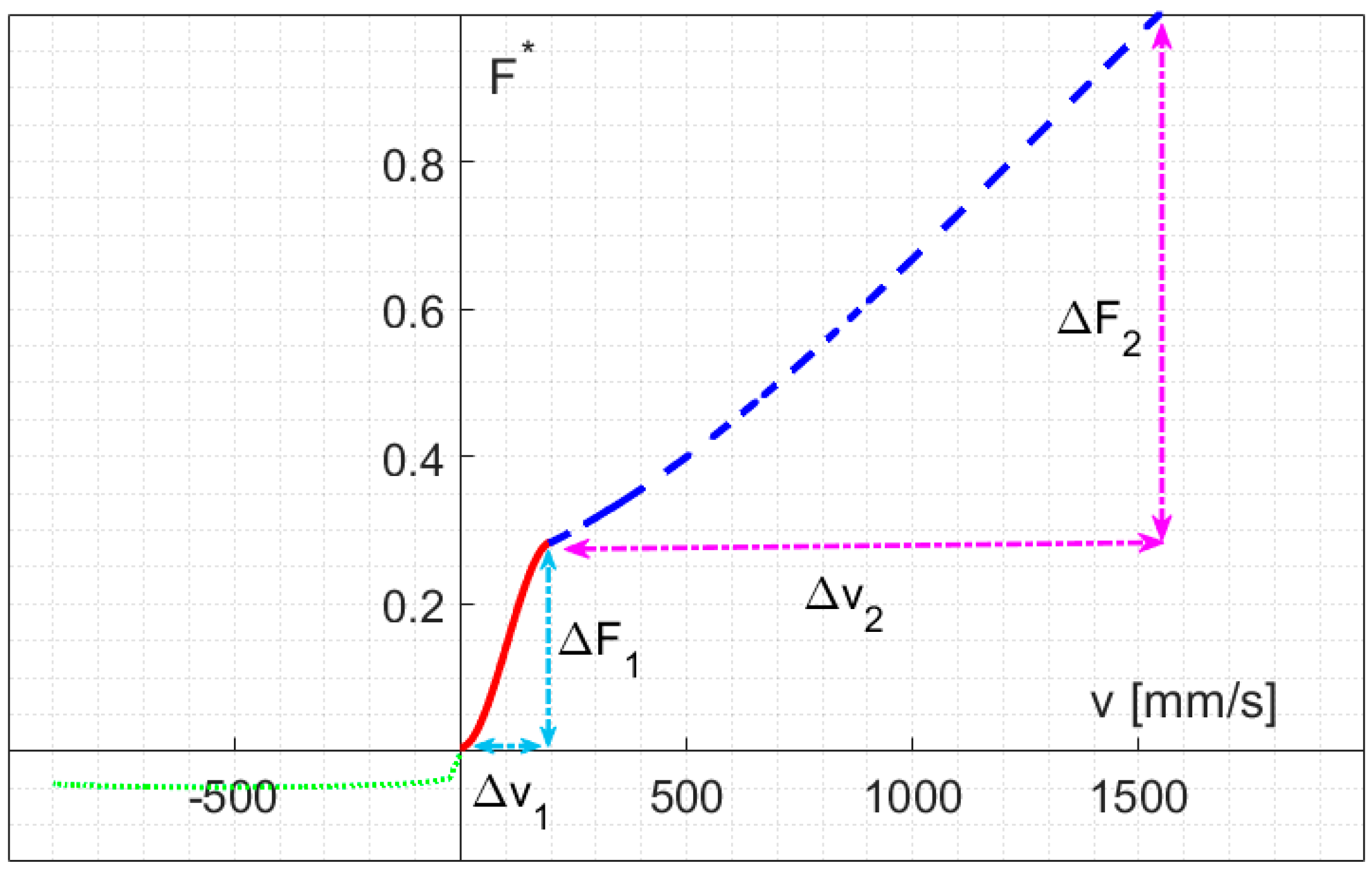
The design strategy and performance evaluation of an EC damper [24] were illustrated in a previous work, in which a multi-physics framework was adopted, and the final predictions were experimentally validated against laboratory damping test results. The aim of this work was to present an evolution of the previous device by combining a new regenerative function, hereinafter named REC damper. The main difference in hardware between the REC damper and the earlier EC damper concerns the outer conductor, which consists of an array of three-phase (A, B, C), concentric, multi-turn coils, instead of a single solid copper tube. Figure 1 shows the main constituent parts of the REC damper, along with its nomenclature. The moving piston includes an array of axially magnetised neodymium permanent magnets (PMs) and iron poles (IPs). Only one single module is displayed in Figure 1 for clarity reasons. The number of modules can be increased to yield the optimal output required for the target application which, in this case, refers to a B-class passenger vehicle. The nonlinear, normilsed maximum damping force ( versus piston speed characteristics of a reference hydraulic shock absorber is depicted in Figure 2. As can be seen, the entire curve can be linearised into three basic piston speed intervals. The initial damping in the first quadrant is represented by the () slope of the straight line, where it coincides with ΔF1, and corresponds to a blow-off pressure at 0.2 m/s piston velocity. The slope decreases for an increasing piston velocity (). The damping coefficient is rather small in the third quadrant (). The proposed REC damper is not designed to bear such loads as those encountered for double wishbone front suspension. The upper bound for the outer diameter, of the damper is 84 mm.
2.2. Electromagnetic Model
The novel REC damper was designed according to the same methodology previously presented for an EC damper [24]. The external load (Figure 3) that acts on the REC damper is electrically connected to each phase of the coils. This is considered as an external variable load resistance, . The REC damper, when in output mode, can provide a damping function or electric power. The latter is controlled by varying the load resistance, [19,20,21,22,25].
The electromotive force, Vemf, for each coil can be expressed in terms of the Faraday—Lenz law as:
where is the flux through each turn of the coil and is the axial velocity of the PMs. Assuming the magnetic flux through the coils is caused by Br (the radial component of the magnetic flux density), the flux can be rewritten as:
The EMF can also be written as [19]:
where is the average radial magnetic flux density in a region, and L is the circumferential length of the coil. Given an EMF, the current flowing in a short circuit coil (RL = 0) of an cross section area can be determined as:
while the power generated in each coil in the short circuit is given by:
Thus, analogously to the EC damper [1], since the power output of the REC damper is a square function of Br, its effect can be maximised, even for a small increase. A similar benefit also results from in Equation (3). Dimensionless quantities are preferred for damping coefficient C* = C/Cmax, damping force F* = Fd/Fmax, and power P* = P/Pmax for easy comparison purposes.
2.3. Quarter Car Dynamic Model
A quarter car model can be used to assess the performance of the REC damper at the design stage by following its modified damping characteristics. A quarter car model allows the dynamics of a front corner of a cruising passenger vehicle to be simulated using a standard (ISO 8608) road profile. Figure 3 sketches such a case with 2 degrees of freedom (DoF), namely, sprung mass ms and unsprung mass mus. The suspension spring stiffness ks, damping coefficient cs, tire stiffness kt and damping ct are set as linear coefficients.
The dynamic equation for the 2-DoF system (Figure 4) can be written as follows, assuming that the tire damping coefficient, which is usually very small, is neglected:
where , , indicate the acceleration, velocity, and displacement, respectively. The model is fed by road profile, , which is generated by filtering a unit power, spectral density, white noise signal with a first-order filter [13]:
where is the road roughness, and is the cruise velocity of the vehicle considered. The cut-off frequency, is given by:
where
The metrics used to evaluate the ride comfort, road holding and safety within a quarter car model are those suggested by Zuo and Zhang [26].
The sensitivity of humans to vibrations is related to the rms acceleration, as specified in the ISO 2631 standard [27]. Ride comfort is assessed, when using a quarter car model, by filtering the sprung mass acceleration using:
and calculating the rms value for each condition.
Similarly, contact between the tire and the road is ensured by the road holding and safety index, which is mathematically expressed as
As the road profile is a random signal, the rms value is used to assess the road holding and safety index. Such an index should be kept below unity to avoid a loss of tire contact with the ground.
Table 1 lists the parameters used in the quarter car model. A velocity dependent damping coefficient was assumed.
2.4. Mesh Sensitivity
The assessment of mesh sensitivity is a crucial step of any finite element analysis. It becomes even more critical for multi-physics computation, since several coupled fields can only converge when the mesh discretization error is minimal for each field. The optimal discretisation strategy undertaken here is the same as that used for the previous work [24]. The pure simplified EC damper geometry, which represents the worst scenario, was considered to assess the mesh sensitivity for thermal field. Here, the overall domain geometry of the REC device was discretised using tetrahedral and brick elements for the magnetic and thermal fields. Table 2 shows details of three analysed mesh discretization levels at the region around the sliding piston for the magnetic field.
The mesh sensitivity to the electromagnetic field was analysed, in terms of computational time and model accuracy, over the damping force, under short circuit and maximum harvested power conditions. The optimal element density was, thus, determined through an iterative procedure. The solution for both the normalised force and output power progressively became more accurate for an increasing mesh resolution, as shown in Figure 5a,b. Only the electromagnetic problem with 1852 elements reached convergence within a reasonable simulation time.
When assessing the mesh sensitivity of the thermal field, coupled with CFD, an extremely fine mesh in the fluid domain, especially in the air gap, is required for convergence. Thus, distinct mixed tetrahedral and brick elements (from those used for the electromagnetic field) were selected to analyse the sensitivity of the temperature field in the mid-stroke region of the conductor. Figure 6 shows the predicted temperature evolution for the three assessed mesh densities. The mesh discretization with 1852 elements proved optimal for convergence in a reasonable simulation time. However, the simulation time was particularly sensitive to the air gap discretisation. All of the relatively coarse mesh configurations led to very small-time steps in the backward differentiation scheme, when combined with the robust PARDISO direct solver.
3. Results
3.1. REC Damper FE Optimisation
The most significant task for the optimal design of the proposed REC was to maximise both the regenerative power and damping performances. This can be achieved by increasing the magnetic flux that passes through the three phase coils when the geometrical parameters are varied. In order to obtain safe operation of the suspension, we aimed to maximise the damping of the REC damper while maintaining the limits in volume of the reference hydraulic shock absorber. The damping coefficient could then be enhanced by optimising the piston arrangement under the volume constraints (piston optimisation). The heights of the PM and IP were set equal, and the non-linear B-H characteristics of pure iron (ARMCO) were used to simulate the behaviour of IPs and back iron (iron and steel tubes).
Figure 7a shows the change in the damping coefficient as a function of the pitch size (τp, in Figure 1). Its maximum value was attained for a ratio of the pitch size-to-the height of the piston (ζ) equal to 0.18. This ratio determined the pitch size that maximised the damping coefficient. The damping coefficient should then be maximised with respect to the IP height-to-pole pitch size ratio, as we previously demonstrated in [24]. The maximum value of the proposed REC device was attained at 0.27 of the aforementioned ratio, which was within the previously found range of 0.21–0.29 [24]. The linear damping condition found here for the REC could be compared with the reference hydraulic damper shown in Figure 7b. As can be noted, the two damping conditions were only comparable for high piston speed conditions, which meant that the suspension handling requirements could not be satisfied. Therefore, a much larger damping capacity was still necessary for the REC damper. However, we were able to take the predicted REC damping coefficient (Figure 7b) as a reference (Cref), and further tune it over the remaining free parameters (stator optimisation) to obtain the damping coefficient of the hydraulic damper.
From a virtual point of view, the tuning parameters can be the magnetic remanence or the external radii of PMs and the electrical conductivity of the conductor. However, the magnetic remanence and electrical conductivity pose less freedom of variability in practice. Thus, the change in the outer diameter of PMs was selected for further tuning on Cnew, while keeping the thickness of the conductor and that of the back steel constant. According to Figure 1, the change in the PM radii affects the outer radius of the tube, and the latter, in turn, affects the mass of the piston. Thus, these two components should be changed accordingly. The resulting tuning procedure of Cnew (starting from Cref) is shown versus the normalised outer radius of the damper tube (rnew/rref) in Figure 8a (left axis). The corresponding CMnew/CMref ratio of the specific damping coefficients (CM is the damping coefficient divided by the mass of the piston) is shown in the same figure (dotted curve) on the right axis.
Tuning the outer tube diameter up to 80.2 mm resulted in the damping force versus piston velocity shown in Figure 8b (cyan dashed line), where the heights of the PMs and IP were kept identical when comparing them with the reference hydraulic damper (blue line).
The same figure shows the closure optimisation adjustment of the REC device obtained by re-invoking the initial piston optimisation strategy (red dash-dot line). It can be noted how the low-speed F-v performance characteristics approach the reference hydraulic damper, thereby resulting in a further increase in the damping coefficient in the final adjustment step of the design procedure.
The REC damper geometry having been optimized, the next steps were devoted to the design of the regenerative part, i.e., the stator (coil and back iron). The height of a single-phase coil is equal to the pitch divided by three [28,29]. The shape of the excitation introduced by the road affects the voltage amplitude and its time function across the resistor. The latter represents the electrical load. Figure 9 shows the open circuit voltage in three central phases of the stator. Each phase of the multiturn coil consisted of a fine 0.25 mm diameter wire and 0.9 PF. The system responses of each phase were computed using an FE model (continuous lines) and an analytical model (dashed lines). The results demonstrated that a perfect matching existed between the numerical and analytical methods for a wheel saw-tooth excitation of 10 Hz.
In an attempt to balance any eventual reduction of the specific damping coefficient, the mass of the piston was previously reduced, for the given constant PF, i.e., the inner radius of the PMs was reduced by 3 mm. Accordingly, the computed damping coefficient was decreased by 88.2% of its initial value.
Upon controlling the electrical load resistance, the damping coefficient can be varied as a piecewise function of the velocity. The power output of the damper is maximum when the electrical load resistance matches the internal resistance of the multiturn coils [25,28], and damping is maximum in the short circuit condition (Rext = 0).
Moreover, the damping and power regeneration performances of the REC were highly dependent on the back iron properties. Figure 10a shows the hysteresis loops of two possible candidate back iron materials, that is, SAE 4340 steel and Armco pure iron. The Armco pure iron is supplied in a recrystallised (annealed) form. The manufacturer’s datasheet indicates 2.1 T saturation and 120 A/m coercivity [30]. Figure 10b displays the computed damping and power output of the REC damper as a function of the circuit load resistance at 10 Hz, and a quarter-pitch amplitude sinusoidal oscillation. The cycle-averaged power shown in Figure 10b (right axes) was maximum when the load resistance matched an internal resistance of 16.667 Ω. The figure compares the cases of a non-linear initial magnetisation curve (dashed) and that of a hysteresis loop for both of the selected back iron materials. The introduction of a hysteresis loop model, that is, of the Jiles—Atherton type, into the FE model led to a decrease in both the damping and the electric power output for the back iron materials, SAE 4340 steel (dash-dot line) and Armco iron (continuous). The former markedly affected both performances, due to its smaller saturation and high coercivity. The latter exhibited superior properties and a prompt market availability. The damping coefficient (C*), after optimal back iron material selection, decreased to 80% in the short circuit condition. Such a decrease in damping coefficient implied the occurrence of C2 damping at a lower resistance, which now operated in the higher power output range, as shown in Figure 10b by the leftward shift of the vertical green line from 33 to 21 Ω. Thus, SAE 4340 steel was selected to manufacture the external tube (1.6 mm thick), because of its outstanding bearing properties, whereas Armco iron was selected for the back iron, because of its superior ferromagnetic properties. However, Armco pure iron was avoided for the manufacturing of the outer external tube, as its low strength would induce on-service straining in the outer tube as well as in the inner (back iron) tube. The latter, in turn, would gradually and irreversibly deteriorate its magnetic hysteresis properties [30,31,32].
Finally, the overall design and optimisation process of the REC damper led to an overall increase in dimension of up to 81.2 mm in diameter, thereby allowing C1′ = 0.853 C1 damping in the short circuit condition, while C2′ damping operated at 21 Ω, and C3′ = 6.7 C3 in the open circuit condition.
3.2. Ride Comfort and Handling
The design, turning and optimisation stages of the REC damper illustrated in the previous sections led to a 14.7% reduction in the damping performance, with respect to its reference counterpart. This might affect safe vehicle cruise and vehicle dynamics performance indices, ride comfort and road holding. A quarter car MATLAB Simulink model was constructed to assess the inherent performance indices. Its input data consisted of the measured vehicle parameters (see Table 2) and the computed damping coefficients for different velocities. The latter were modelled as piecewise functions. Simulations were run assuming two ISO standard class road profiles [33], that is, a good quality B-class and an average quality C—class, for a variable vehicle cruise velocity ranging from 1 to 100 km/h. It should be recalled that ride comfort is determined as the RMS acceleration of the vehicle body weighted by the human—vibration sensitivity curve. The results of the REC damper were compared with those of the reference hydraulic damper in Figure 11a,b. No change in comfort was attained for the REC damper on both class roads. However, road holding was degraded for an increasing vehicle velocity in both types of dampers. As a result of the softer damping performance of the REC damper, the road holding index increased slightly on B class road but remained below unity at all the investigated velocities. These results also confirmed that high vehicle velocities increased the risk of losing tire-road contact on rough roads.
Figure 12 depicts the profiles of the average piston speed of the REC damper versus vehicle velocity. The rms piston speed could reach up to 0.135 and 0.31 m/s for vehicle velocities of up to 100 km/h, in the case of B-class and C-class roads, respectively. This could be very useful information for the subsequent thermal design of the REC damper. With reference to a New European Driving Cycle with an average vehicle velocity of 35 km/h [13], a piston average speed of 0.17 m/s could be used for C-class roads as a reference to measure the regenerative power (15 W average power).
3.3. Thermal Behaviour of the REC Damper
The thermal performance of the REC damper was assessed assuming a sinusoidal piston displacement of the magnetic piston (4.5 mm amplitude and 15 Hz frequency). This configuration corresponded to a vehicle cruising on a C-type ISO standard road at a cruising velocity of 100 km/h (rms piston speed 0.3 m/s, Figure 11), with reference to the short circuit scenario (C1), even for piston speeds faster than 0.2 m/s, to account for any failure in the power electronics.
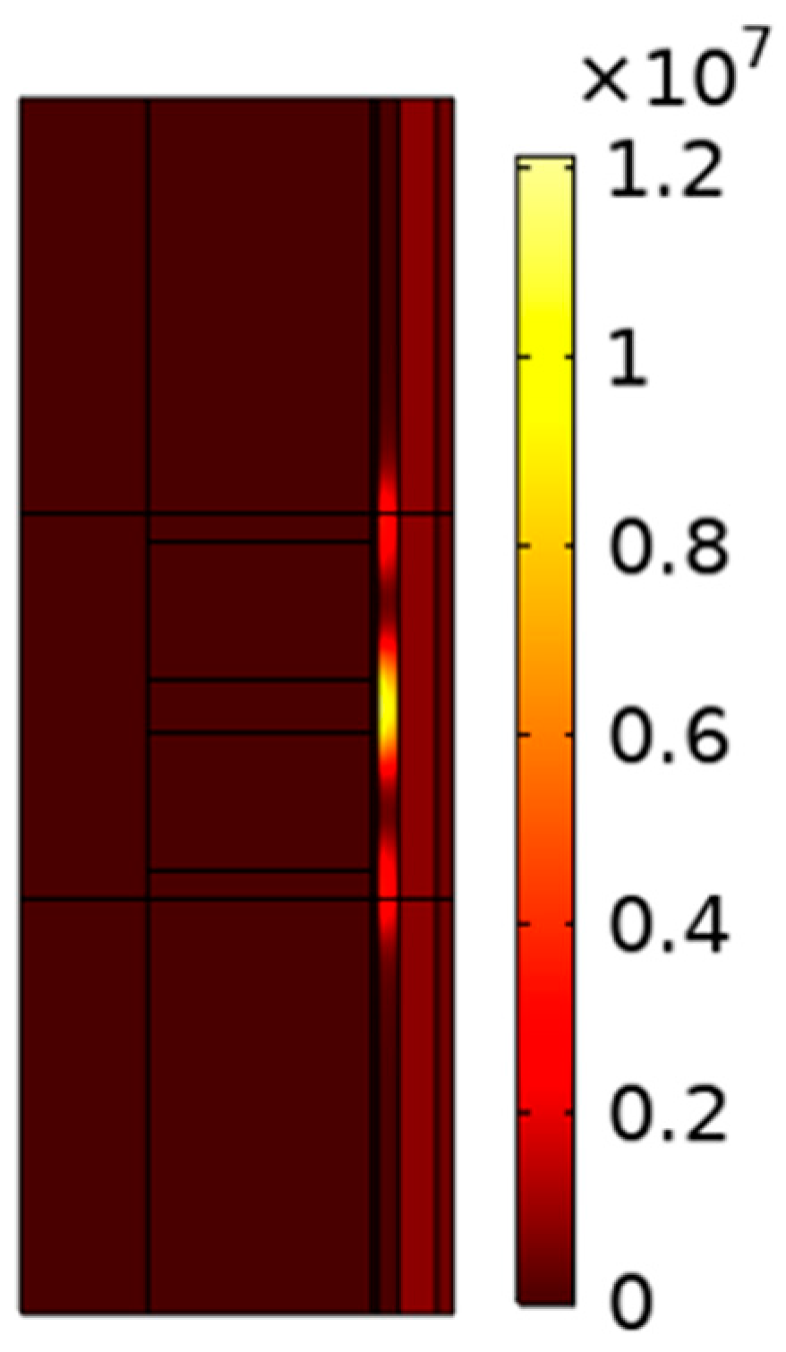
The conductor was modelled as a single Cu tube to minimise the mesh sparsity of the FE model. This implied that a full PF was taken into account for the conductor and, thus, more energy was dissipated in the system. The volumetric cycle averaged power loss density computed for the system is shown in Figure 13. The power density peak was located at mid length of the conductor tube, as relatively small displacement amplitudes were considered.
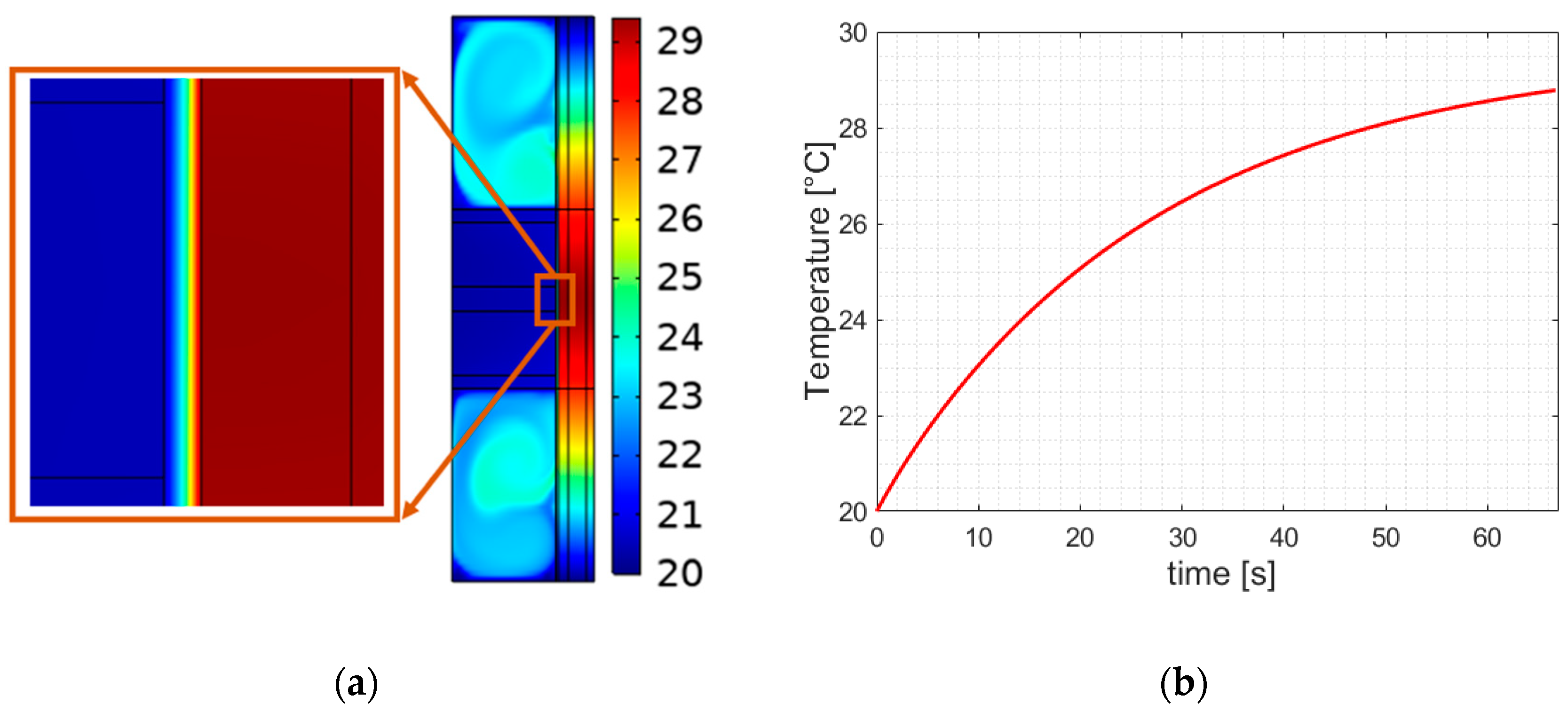
Figure 14a displays the predicted temperature field across the system. The figure also confirmed that the hot air passing through the air gap underwent an effective mixing in the upper chamber during the downward motion of the piston. This suggested that the cooling effect of trapped air inside the REC damper was sufficient to cool the damper (self-cooling), without the need for any auxiliary external means. Although the dissipated power in the system was overestimated, the piston PMs operated under regular temperature conditions. The average temperature history at the mid layer of the stator is shown in Figure 14b. After a sufficient time, this temperature tended to reach equilibrium, which meant that the heat dissipation and generation in the system could conveniently balance each other out, in agreement with our previous work on a pure EC damper [24].
4. Discussion
In the previous sections, an existing multi-physics model that can be used for design purposes, and which was developed and calibrated to design and optimise an EC damper, was utilised, on the basis of its damping performances, to design a novel REC damper. It was then optimised, in terms of a new complementary factor, using a regenerated electric power output, which would otherwise be lost. Efforts were made during the design phase to replicate the reference maximum force—velocity curve of the hydraulic damper present in the target REC damper, since it had already undergone decades of successful development to harmonise the comfort and handling performances of vehicles [2]. Such an approach guaranteed safe vehicle handling, even in the case of failure of the regeneration electronic circuit system. The predicted regenerated power versus load resistance and the damping coefficient versus load resistance characteristics, which are displayed in Figure 7b, closely resembled those of an electromagnetic damper [20]. Moreover, the geometric features of the proposed REC damper were in line with those of other electromagnetic dampers [20,21,22,28].
The predicted voltage curves shown in Figure 6 matched well with those computed analytically [19]. Moreover, our methodology proved that damping is insensitive to the final multiturn coil wire diameter [20,28]. Indeed, this size is dictated by the fact that the power electronics circuit is the primary factor that determines its overall electrical resistance and inductance. As a result, the computed voltage amplitude decreases (while the associated current increases) as the coil wire diameter increases [22].
The successful comparisons with existing monolithic dampers or regenerators, as well as those with regenerative electromagnetic or hydraulic dampers, all contributed toward validating our proposed optimal design methodology of the REC device.
The proposed methodology also indicates the presence of limits in the achievable performances of the REC damper and its inherent effects on the dynamics of the vehicle. One of these limits is the larger and uncontrollable damping of back iron. Despite the favourable benefits of increased back iron damping, large values of compression stroke damping may negatively affect the dynamics of a vehicle over road bumps [2]. The literature [33] suggests proportions ranging from 20/80 to 50/50 for bump and rebound damping, respectively, for passenger cars. The predicted bump damping in the designed REC damper only amounted to 16% of the rebound, which meant that its value was still acceptably low. This suggested that the selected simplified tubular configuration of back iron could still be safely used in place of the more complicated configuration offered by thin sheets used for a limiting eddy current flow in a circumferential direction.
Figure 11a,b show how a low-speed damping (C1) decrease and a bump damping (C3) increase, resulting from the effects of back iron, influence the dynamics of a vehicle. The comfort performance of a vehicle equipped with an REC damper experiences minimal changes on both class roads, whereas the road holding index is slightly deteriorated on B class roads. The latter performance index is more sensitive to damping changes. Figure 12 shows the RMS piston velocity range for the analysed cruise velocities of the vehicle. Maximum RMS values were found at 0.135 and 0.31 m/s for B class and C class roads, respectively. The low piston speed damping coefficient (C1) is predominant within such piston speed ranges for B class road. Consequently, the road holding index is affected more, thereby confirming our analysis results shown in Figure 11a,b.
The frequency response of the transfer functions between road disturbance and sprung mass in the quarter car model is shown in Figure 15, for a typical frequency range of vehicle suspensions. The response was investigated every 500 Ns/m over a damping coefficient interval, starting from an undamped system (blue curve) up to a 2000 Ns/m damping coefficient. An increase in the damping coefficient at lower frequencies provided favourable vibration filtering, whereas the undamped system underwent a better attenuation at larger frequencies than the natural frequency of the unsuspended mass. Thus, in accordance with the results computed by Fukushima et al. [2], we found that severe damping (arrow direction) was more convenient at lower frequencies than at higher frequencies.
The heat dissipation induced by damping affects the temperature field. This is shown in Figure 14a,b. This suggests that, even in the case of an electronics failure, the REC damper functioned properly, because the temperature field of the PMs stayed close to room temperature. Although a close coupling between the magnetic analysis and the thermal field analysis was computationally highly costly, when using the transient CFD approach, we suggest that it is the right price to pay to be able to assess that any small change in the design does not involve intolerable changes in temperature. Such changes would irreversibly impair the overall performances of the REC damper, especially during the design stage, in the absence of experimental tests. Moreover, the CFD approach only requires a small number of correlations [34].
A limitation in the selected vehicle dynamics analysis was the use of a simple and very common quarter-car model (Figure 4). This model is suitable for predicting vertical heave motions in the 0 to 50 Hz frequency range, but it does not take into account either pitch or roll motion dynamics [35]. In fact, a more comprehensive analysis should include a full vehicle model with appropriate tyre [36] and bushing contributions [37] for various driving conditions and road surfaces [2]. Furthermore, a single tyre—road contact and a rigid-joint approach may lead to an overestimation of vehicle dynamic excitations, thereby yielding higher energy regeneration power.
It is well-known, in the electric motor technology context, that a linear electric motor exhibits a lower electric energy density than its rotary counterparts. Thus, the proposed linear REC damper has a lower energy density than both its rotary electro-mechanical and rotary electro-hydraulic counterparts. However, the REC damper is a better and more straightforward choice, especially to upgrade a conventional vehicle suspension damper, since no linear-to-rotary transmission mechanisms are involved. The proposed design methodology is primarily addressed at achieving an optimisation of safe damping performance, while electric power generation is just a supplementary feature for green vehicles. The complexities introduced with such technologies are the price to pay to obtain fossil-free features. The predicted energy saving of 15 W, resulting from the use of a quarter-car model, suggested a nearly 4-fold (equal to 60 W) power harvesting, for a full-car model for an average vehicle velocity of 35 km/h, (New European Driving Cycle on ISO C-class roads). The predicted electric power was an average value, whereas the instantaneous values varied according to the piston speed (excitations) and could reach up to 2 m/s.
5. Conclusions
This work presents an FE multi-physics design methodology and its application for the optimal design of a regenerative eddy current damper for a B class automotive suspension system. The proposed multi-physics methodology follows previously presented, and successfully demonstrated, methodology used for the design of an EC damper. The performances of the proposed REC damper were optimised for the highest possible force density, were compatible with the available suspension volume, and had special reference to fail-safe eddy current damping.
The damping (and the regenerative) performances of the proposed REC device were designed so that they could be varied by adjusting the external resistance load connected to the coils on the basis of the measured force-velocity characteristics of a target hydraulic shock absorber, which was used in this study as a reference.
The vehicle dynamics characteristics of the proposed REC damper were benchmarked against a target hydraulic damper, using a quarter car computed model. The computed comparative results showed that the comfort index did not change markedly over the investigated vehicle velocity range. On the other hand, the road holding index, obtained using the reference methodology, deteriorated slightly, due to the lower damping coefficient related to material and space limitations, although it still fell within safe limits.
The multi-physics design approach showed benefits as a self-consistency aiding tool for the systematic analysis of the performance of an REC damper, only requiring a minimal amount of experimental data. The predictions clearly showed that the minimal damping coefficient, associated with the compression stroke of a conventional shock absorber, was unattainable for electromagnetic dampers, as the electric resistance of tubular back iron could not be easily controlled. The predictions also showed that the REC damper could harvest 15 W continuous power on C class ISO roads at a vehicle cruise speed of 35 km/h, and, at the same time, could guarantee safe road holding and damping under short circuit conditions. The predicted temperature field, based on the CFD analysis, revealed that the REC damper could function safely, even during malfunctioning of the electronic circuit, and provide safe damping under short circuit conditions.
The proposed REC damper can be considered as a green, transmission mechanism-free substitute for conventional hydraulic dampers, as oil by-products are prevented, and the vibrational power is advantageously converted into electric power, while meeting damping requirements.
An REC damper prototype is currently under development as a proof of concept. Its experimental performances, and details about the research into the involved power electronics for electric power storage, will be the subject of a future publication.
Author Contributions
Conceptualization, G.M. and U.J.; methodology, G.M. and U.J.; software, F.P. and U.J.; validation, U.J.; formal analysis, F.P. and U.J.; investigation, F.P., G.M. and U.J.; resources, G.M.; data curation, U.J.; writing—original draft preparation, G.M. and U.J.; writing—review and editing, G.M. and U.J.; visualisation, U.J.; supervision, G.M. and U.J.; project administration, G.M.; funding acquisition, G.M and U.J. All authors have read and agreed to the published version of the manuscript.
Funding
This research received no external funding.
Acknowledgments
The authors would like to acknowledge the sincere efforts and valuable time given by Sanjar Ruzimov (TTPU). His invaluable advice has helped to complete this article.
Conflicts of Interest
The authors declare no conflict of interest.
References
- Reimpell, J.; Stoll, H.; Betzler, J. The Automotive Chassis: Engineering Principles; Elsevier: Amsterdam, The Netherlands, 2001. [Google Scholar]
- Fukushima, N.; Hidaka, K.; Iwata, K. Optimum characteristics of automotive shock absorbers under various driving conditions and road surfaces. Int. J. Veh. Des. 1983, 4, 463–467. [Google Scholar]
- Zhang, Y.; Guo, K.; Wang, D.; Chen, C.; Li, X. Energy conversion mechanism and regenerative potential of vehicle suspensions. Energy 2017, 119, 961–970. [Google Scholar] [CrossRef]
- ISO 8608:1995; Mechanical Vibration-Road Surface Profiles-Reporting of Measured Data. ISO: Geneva, Switzerland, 2011.
- Li, Z.; Brindak, Z.; Zuo, L. Modeling of an Electromagnetic Vibration Energy Harvester with Motion Magnification. In Proceedings of the ASME International Mechanical Engineering Congress and Exposition, IMECE 2011, no. PARTS A and B, Denver, CO, USA, 11–17 November 2011; Volume 7, pp. 285–293. [Google Scholar] [CrossRef]
- Li, Z.; Zuo, L.; Kuang, J.; Luhrs, G. Energy-harvesting shock absorber with a mechanical motion rectifier. Smart Mater. Struct. 2012, 22, 025008. [Google Scholar] [CrossRef]
- Amati, N.; Festini, A.; Tonoli, A. Design of electromagnetic shock absorbers for automotive suspensions. Veh. Syst. Dyn. 2011, 49, 1913–1928. [Google Scholar] [CrossRef]
- Tonoli, A.; Amati, N.; Detoni, J.G.; Galluzzi, R.; Gasparin, E. Modelling and validation of electromechanical shock absorbers. Veh. Syst. Dyn. 2013, 51, 1186–1199. [Google Scholar] [CrossRef]
- Liu, Y.; Xu, L.; Zuo, L. Design, Modeling, Lab, and Field Tests of a Mechanical-Motion-Rectifier-Based Energy Harvester Using a Ball-Screw Mechanism. IEEE/ASME Trans. Mechatron. 2017, 22, 1933–1943. [Google Scholar] [CrossRef]
- Audi Developing Electromechanical Rotary Dampers; Potential for Energy Recuperation from Suspension; 48V. Available online: https://www.greencarcongress.com/2016/08/audi-developing-electromechanical-rotary-dampers-potential-for-energy-recuperation-from-suspension-4.html (accessed on 13 March 2022).
- Galluzzi, R.; Circosta, S.; Amati, N.; Tonoli, A. Rotary regenerative shock absorbers for automotive suspensions. Mechatronics 2021, 77, 102580. [Google Scholar] [CrossRef]
- Li, C.; Zhu, R.; Liang, M.; Yang, S. Integration of shock absorption and energy harvesting using a hydraulic rectifier. J. Sound Vib. 2014, 333, 3904–3916. [Google Scholar] [CrossRef]
- Galluzzi, R.; Tonoli, A.; Amati, N.; Curcuruto, G.; Conti, P.; Greco, G.; Nepote, A. Regenerative Shock Absorbers and the Role of the Motion Rectifier; SAE Technical Paper: Warrendale, PA, USA, 2016. [Google Scholar] [CrossRef]
- Galluzzi, R.; Xu, Y.; Amati, N.; Tonoli, A. Optimized design and characterization of motor-pump unit for energy-regenerative shock absorbers. Appl. Energy 2018, 210, 16–27. [Google Scholar] [CrossRef]
- Zhang, Y.; Chen, H.; Guo, K.; Zhang, X.; Eben Li, S. Electro-hydraulic damper for energy harvesting suspension: Modeling, prototyping and experimental validation. Appl. Energy 2017, 199, 1–12. [Google Scholar] [CrossRef]
- Guo, S.; Xu, L.; Liu, Y.; Guo, X.; Zuo, L. Modeling and experiments of a hydraulic electromagnetic energy-harvesting shock absorber. IEEE/ASME Trans. Mechatron. 2017, 22, 2684–2694. [Google Scholar] [CrossRef]
- Karnopp, D. Permanent Magnet Linear Motors Used as Variable Mechanical Dampers for Vehicle Suspensions. Veh. Syst. Dyn. 2007, 18, 187–200. [Google Scholar] [CrossRef]
- Ebrahimi, B.; Khamesee, M.B.; Golnaraghi, F. Eddy current damper feasibility in automobile suspension: Modeling, simulation and testing. Smart Mater. Struct. 2008, 18, 015017. [Google Scholar] [CrossRef]
- Zuo, L.; Scully, B.; Shestani, J.; Zhou, Y. Design and characterization of an electromagnetic energy harvester for vehicle suspensions. Smart Mater. Struct. 2010, 19, 045003. [Google Scholar] [CrossRef] [Green Version]
- Ribeiro, R.; Asadi, E.; Khamesee, M.B.; Khajepour, A. Hybrid variable damping control: Design, simulation, and optimization. Microsyst. Technol. 2014, 20, 1723–1732. [Google Scholar] [CrossRef]
- Asadi, E.; Ribeiro, R.; Khamesee, B.; Khajepour, A. Analysis, Prototyping, and Experimental Characterization of an Adaptive Hybrid Electromagnetic Damper for Automotive Suspension Systems. IEEE Trans. Veh. Technol. 2017, 66, 3703. [Google Scholar] [CrossRef]
- Friedrich, L.A.J.; Paulides, J.J.H.; Lomonova, E.A. Modeling and Optimization of a Tubular Generator for Vibration Energy Harvesting Application. IEEE Trans. Magn. 2017, 53, 2710232. [Google Scholar] [CrossRef]
- Pu, H.; Li, J.; Wang, M.; Huang, Y.; Zhao, J.; Yuan, S.; Peng, Y.; Xie, S.; Luo, J.; Sun, Y. Optimum design of an eddy current damper considering the magnetic congregation effect. J. Phys. D Appl. Phys. 2020, 53, 115002. [Google Scholar] [CrossRef]
- Jamolov, U.; Maizza, G. Integral Methodology for the Multiphysics Design of an Automotive Eddy Current Damper. Energies 2022, 15, 1147. [Google Scholar] [CrossRef]
- Kleijer, M.; Friedrich, L.A.J.; Gysen, B.L.J.; Lomonova, E.A. Dynamic Analysis of a Tubular Generator for Automotive Suspension Applications; Dynamic Analysis of a Tubular Generator for Automotive Suspension Applications. In Proceedings of the 2019 12th International Symposium on Linear Drives for Industry Applications (LDIA), Neuchatel, Switzerland, 1–3 July 2019. [Google Scholar]
- Zuo, L.; Zhang, P.S. Energy harvesting, ride comfort, and road handling of regenerative vehicle suspensions. J. Vib. Acoust. Trans. 2013, 135, 011002. [Google Scholar] [CrossRef]
- ISO 2631; Mechanical Vibration and Shock—Evaluation of Human Exposure to Whole-Body Vibration—Part 1: General Requirements. ISO: Geneva, Switzerland, 1997.
- Asadi, E.; Ribeiro, R.; Khamesee, M.B.; Khajepour, A. A new adaptive hybrid electromagnetic damper: Modelling, optimization, and experiment. Smart Mater. Struct. 2015, 24, 075003. [Google Scholar] [CrossRef]
- Gysen, B.L.J.; Member, S.; Janssen, J.L.G.; Paulides, J.J.H.; Lomonova, E.A.; Member, S. Design Aspects of an Active Electromagnetic Suspension System for Automotive Applications; Design Aspects of an Active Electromagnetic Suspension System for Automotive Applications. IEEE Trans. Ind. Appl. 2009, 45, 1589–1597. [Google Scholar] [CrossRef] [Green Version]
- ARMCO®. Available online: https://www.aksteel.nl/files/downloads/172888_armco_pure_iron_pdb_euro_final_secured_92.pdf (accessed on 18 February 2022).
- Naumoski, H.; Maucher, A.; Herr, U. Investigation of the influence of global stresses and strains on the magnetic properties of electrical steels with varying alloying content and grain size. In Proceedings of the 2015 5th International Electric Drives Production Conference (EDPC), Nuremberg, Germany, 15–16 September 2015. [Google Scholar]
- Shokrollahi, H. The magnetic and structural properties of the most important alloys of iron produced by mechanical alloying. Mater. Des. 2009, 30, 3374–3387. [Google Scholar] [CrossRef]
- Dixon, J.C. The Shock Absorber Handbook; John Wiley & Sons: Hoboken, NJ, USA, 2008. [Google Scholar]
- Boglietti, A.; Cavagnino, A.; Staton, D.; Shanel, M.; Mueller, M.; Mejuto, C. Evolution and Modern Approaches for Thermal Analysis of Electrical Machines; Evolution and Modern Approaches for Thermal Analysis of Electrical Machines. IEEE Trans. Ind. Electron. 2009, 56, 871–882. [Google Scholar] [CrossRef] [Green Version]
- Genta, G.; Morello, L. The Automotive Chassis: Volume 2, System Design; Springer: Dordrecht, The Netherlands, 2009. [Google Scholar]
- Yang, S.; Lu, Y.; Li, S. An overview on vehicle dynamics. Int. J. Dynam. Control 2013, 1, 385–395. [Google Scholar] [CrossRef] [Green Version]
- Rueda, I.; Maizza, G.; Jamolov, U. Impact of Suspension Bushing’s Rigidity in a Real Car’s Dynamic Response. Master’s Thesis, Politecnico di Torino, Turin, Italy, 2020. [Google Scholar]
Figure 1.
Cross section view of the REC damper with its constituent parts and nomenclature.

Figure 2.
Piecewise linearisation of the nonlinear, normalised maximum force () vs. piston speed characteristics of the reference hydraulic shock absorber (of a typical B-class passenger-vehicle) used in this work for the design and optimisation of the REC damper.
Figure 2.
Piecewise linearisation of the nonlinear, normalised maximum force () vs. piston speed characteristics of the reference hydraulic shock absorber (of a typical B-class passenger-vehicle) used in this work for the design and optimisation of the REC damper.

Figure 3.
Electric circuit used to control the two outputs of the REC damper.

Figure 4.
Schematics of the quarter car model used to benchmark the dynamic indices.

Figure 5.
Mesh sensitivity with an increasing overall number of finite elements (curve parameter): (a) normalised damping force vs. piston speed; (b) normalised harvested power vs. piston speed.
Figure 5.
Mesh sensitivity with an increasing overall number of finite elements (curve parameter): (a) normalised damping force vs. piston speed; (b) normalised harvested power vs. piston speed.

Figure 6.
Mesh sensitivity of the thermal and CFD fields for the analysed time period; the legend indicates the overall number of finite elements in the mesh.
Figure 6.
Mesh sensitivity of the thermal and CFD fields for the analysed time period; the legend indicates the overall number of finite elements in the mesh.

Figure 7.
REC damper optimisation starting from the dimensions of the existing hydraulic damper and using the design model developed in [24]: (a) normalised damping coefficient during piston optimisation as a function of the pitch size-to-the total piston length ratio; (b) comparison of the damping force of the optimised REC (linear) and the reference hydraulic damper shown in Figure 2 (line colours follow explanations of Figure 2).

Figure 8.
Optimisation strategy of the RCE damper versus the normalised outer radius of rnew/rref of the damper tube: (a) damping increase as a ratio of the damping in Figure 7b—Left axis, normalised damping coefficient (true damping coefficient divided by the piston mass)—Right axis; (b) Optimised damping with equal IP and MP heights (cyan dashed line) and optimised as in Figure 4a (red dash-dot line) compared with the reference hydraulic damper (blue line).

Figure 9.
Comparison of the voltage in 3 phases with the analytical model of Equation (3).

Figure 10.
Damping and electric power performances of the REC damper: (a) the SAE 4340 steel and Armco pure iron hysteresis loops considered in the FE design and optimisation process; (b) the normalised damping coefficient curve versus load resistance (left axis) for the back iron material models and periodic cycle-averaged power output of the REC damper versus load resistance (right axis); curves in the legend: the initial magnetisation curve of the Armco iron (dashed), the magnetic hysteresis loop of the Armco pure iron (continuous), and the magnetic hysteresis loop of the SAE 4340 steel (dash—dotted).

Figure 11.
Comparison of the performance indices for the hydraulic reference and REC dampers: (a) ride comfort and (b) road holding safety on ISO B-class and C-class roads for variations of the vehicle cruise speed.
Figure 11.
Comparison of the performance indices for the hydraulic reference and REC dampers: (a) ride comfort and (b) road holding safety on ISO B-class and C-class roads for variations of the vehicle cruise speed.

Figure 12.
Piston RMS speed on B-class and C-class roads for variations of the vehicle cruise velocity.
Figure 12.
Piston RMS speed on B-class and C-class roads for variations of the vehicle cruise velocity.

Figure 13.
Computed volumetric power loss density [W/m3].

Figure 14.
Thermal performance analysis: (a) temperature field; (b) average temperature evolution at the stator mid-stroke location.
Figure 14.
Thermal performance analysis: (a) temperature field; (b) average temperature evolution at the stator mid-stroke location.

Figure 15.
Frequency response transfer function of the road disturbance and sprung mass with a damping coefficient as a curve parameter. The arrows point to increased damping.
Figure 15.
Frequency response transfer function of the road disturbance and sprung mass with a damping coefficient as a curve parameter. The arrows point to increased damping.


Table 1.
The quarter car model parameters used in the benchmark simulations.
| Symbol | Value |
|---|---|
| 333.54 kg | |
| 41.46 | |
| 21.6 kN/m | |
| 194.4 kN/m |
Table 2.
Details of the discretized geometry in the region near the sliding piston and relative overall number of computed finite elements for the magnetic field.
Table 2.
Details of the discretized geometry in the region near the sliding piston and relative overall number of computed finite elements for the magnetic field.
 |  |  | |
| Number of elements | (857) | (1852) | (9134) |
Publisher’s Note: MDPI stays neutral with regard to jurisdictional claims in published maps and institutional affiliations. |
© 2022 by the authors. Licensee MDPI, Basel, Switzerland. This article is an open access article distributed under the terms and conditions of the Creative Commons Attribution (CC BY) license (https://creativecommons.org/licenses/by/4.0/).
Share and Cite
MDPI and ACS Style
Jamolov, U.; Peccini, F.; Maizza, G. Multiphysics Design of an Automotive Regenerative Eddy Current Damper. Energies 2022, 15, 5044. https://0-doi-org.brum.beds.ac.uk/10.3390/en15145044
AMA Style
Jamolov U, Peccini F, Maizza G. Multiphysics Design of an Automotive Regenerative Eddy Current Damper. Energies. 2022; 15(14):5044. https://0-doi-org.brum.beds.ac.uk/10.3390/en15145044
Chicago/Turabian StyleJamolov, Umid, Francesco Peccini, and Giovanni Maizza. 2022. "Multiphysics Design of an Automotive Regenerative Eddy Current Damper" Energies 15, no. 14: 5044. https://0-doi-org.brum.beds.ac.uk/10.3390/en15145044
Note that from the first issue of 2016, this journal uses article numbers instead of page numbers. See further details here.