
Sliding Mode Controller for Parameter-Variable Load Sharing in Islanded AC Microgrid


1
Laboratory for Renewable Energy Systems, Faculty of Electrical Engineering and Computing, University of Zagreb, 10000 Zagreb, Croatia
2
School of Electrical and Computer Engineering, Shiraz University, Shiraz 71441-65186, Iran
*
Author to whom correspondence should be addressed.
Energies 2022, 15(16), 6029; https://0-doi-org.brum.beds.ac.uk/10.3390/en15166029
Submission received: 19 July 2022
/
Revised: 15 August 2022
/
Accepted: 18 August 2022
/
Published: 19 August 2022
(This article belongs to the Special Issue Microgrids 2022)
Abstract
:Controlling voltage, frequency, and current in an islanded microgrid is a challenging problem because the distributed generation sources, stochastic and intermittent in nature, are not connected to the main electricity network to provide stable and clean energy. Therefore, the design of a robust controller to control the output parameters of the islanded microgrid and suppress load variations and disturbances is essential. In this paper, a hysteresis controller is proposed and designed to control the output voltage of an islanded AC microgrid and an improved sliding mode controller (SMC) based on adaptive control principle is designed to control the current of the microgrid. The current controller consists of two parts: An adaptation part, which aims to eliminate disturbances and system uncertainties, and a second part, which aims to deal with the tracking problem of the system under parameter-varying topologies. The adaptation strategy has the advantage of solving the gain tuning problem and chattering reduction. It also requires limited information about disturbance and uncertainties of the system. To validate the proposed control methodology and show its effectiveness, a case study of a simulated islanded microgrid is presented. The results show that the proposed controllers can effectively control the current and voltage underload changes and increase the stability and resilience of the microgrid. The results also reveal that the performance of the proposed controller in terms of total harmonic distortion (THD) and dynamic response overcome the performance of conventional controller by a 4× reduction in THD and 40–200× reduction in settling time.
1. Introduction
A microgrid (MG) generally consists of various distributed generation (DG) resources (renewable and non-renewable resources), storage systems, and loads. Usually, DGs and storage systems are connected to a point of common coupling (PCC), shared DC or AC bus, through power converters. Microgrids have two modes of operation: grid-connected mode and islanded mode. In a grid-connected mode, voltage, and frequency are controlled by the main power network, while in the islanded mode, they are controlled by the distributed generation units or, if necessary, by the distributed storage units. Mathematical modelling of uncertainties and parameter changes in microgrids are identified as one of the greatest challenges for advanced control application [1]. Parameter variations in inverter output filters, internal and external fault disturbances, unpredicted load variations, and harmonic currents generated by nonlinear loads are inevitable events in an islanded microgrid [1]. Therefore, to improve the control performance and suppress the disturbances, robust control techniques are adopted [2,3,4,5].
One of the most challenging technical problems for the internal control design of a microgrid is the control of renewable energy sources (RES), such as wind or solar energy. The intermittent availability of these sources is known to be one of the major threats to the stable operation of the microgrids [6,7,8]. To cope with the challenging operational situations of a microgrid containing RES, many strategies have been proposed for voltage and frequency regulation [9], secondary regulation [10], and reduction of active power cost [11]. Another challenge to achieve high performance and high-quality characteristics of a microgrid in terms of voltage and frequency is the nonlinear behavior of the loads and devices connected to the microgrid. Load non-linearity reduces the overall microgrid performance and degrades power quality characteristics. However, the effects of nonlinear loads, both in voltage and current source models have rarely been studied in the literature [12,13,14].
The literature review of the published work regarding microgrids (MGs) reveals that there are several studies concerning the control methods for MGs. In [15], a control method based on a nominal transfer function of the power plant is proposed. A feed-forward compensator is developed to reduce the load disturbances and maintain the load balance in [16]. The authors of [17] proposed a discrete time sliding mode (SM) controller for unbalanced or nonlinear loads. However, the proposed controller is highly complex for implementation. In [18], a Kalman filter is used for online estimation of parameter changes. The robustness of parameter variation is considered in [19] by introducing an adaptive SM controller. To consider linear and nonlinear loads conditions, a modified SM controller is used in [20]. For a distributed AC power supply system, a control technique is introduced in [21] to share the linear or nonlinear load between paralleled inverters without using control interconnections. The inverter parameter variations and line impedance imbalances are compensated automatically. The authors of [22] applied fuzzy gain scheduling to control the DC current of a microgrid. Intelligent control of frequency is proposed in [23] to monitor the microgrid and to regulate the frequency in the islanding mode. In this method the operation mode of one DGs is changed to a slack busbar. The main drawback of this method is the low robustness of the controller. The control of an islanded network considering the dynamics of the power converter is presented in [24]. An overview of the overall control of the DC microgrids is presented in [25].
In [26], authors presented an integral-based backstepping controller for DG sources in an AC islanded microgrid. Enhancing convergence to a steady state to track error vectors under disturbance and model uncertainties is considered by applying the integral action during the design process of the backstepping. To improve the anti-disturbance capability of a PV system and mitigate the power chattering in a hybrid islanded microgrid, an anti-disturbance finite-time adaptive sliding mode backstepping (DFA-SMB) controller is proposed in [27]. The authors in [28] proposed an equivalent SM control for the stability of an islanded DC microgrid to address limited operations and guarantee global stability of the desired equilibrium point.
To address two different kinds of uncertainties in the system, i.e., the stochastic nature of renewable sources availability such as solar energy, and unpredictable changes in the topology of the system that could occur because of excessive operating conditions and/or natural disasters, a distributed control strategy for the islanded MG clusters is presented in [29]. The authors of [30] proposed an adaptive sliding mode controller based on barrier function for a hybrid AC/DC microgrid. The convergence of the system’s output variable independent of the knowledge of the upper bound of the disturbances is guaranteed by adaptive sliding mode controller based on barrier function.
Table 1 shows a summary of different control strategies of MGs as proposed in the literature.
The aforementioned literature review indicates that the selection and design of a robust, yet fast, controller to regulate the output voltage and current and suppress load changes and disturbances in microgrids are critical. The main objective of this work is to design a nonlinear robust and fast response controller to control the current and load sharing between inverters connected in parallel in an islanded AC microgrid. The proposed controller is suitable for sudden load changes and uncertainties of the system. A hysteresis controller is designed to control the voltage of the islanded microgrid, and an improved sliding mode controller based on adaptive control is designed to control the current of the microgrid to improve its stability and resilience. The microgrid system considered consists of three distributed generators in which the inverters are connected in parallel. One of the three DGs is selected as the voltage regulator while the other two units control the current and load sharing between the inverters. The use of the sliding mode controller based on adaptive control in the case of current control and load sharing increases the stability and robustness of the control system against load changes. While, the hysteresis control methodology has the features of enhanced system stability, raised reliability and high-speed dynamic response to the system changes and is easy to implement. To investigate the proposed design, different loads including asymmetric resistive, inductive-resistive, and nonlinear loads are considered and simulated in MATLAB/Simulink environment and the results demonstrate the effectiveness of the proposed control system. The main contributions of this research work are:
- (1)
- Nonlinear mathematical model of a microgrid with multiple generation system suitable for observer and controller design.
- (2)
- Control structure with an observer and a sliding mode controller, adaptive to load variations, for load sharing in islanded AC microgrid with distributed generation. The contributions are validated in simulation environment and compared to conventional control.
2. Single-Phase Inverter Model
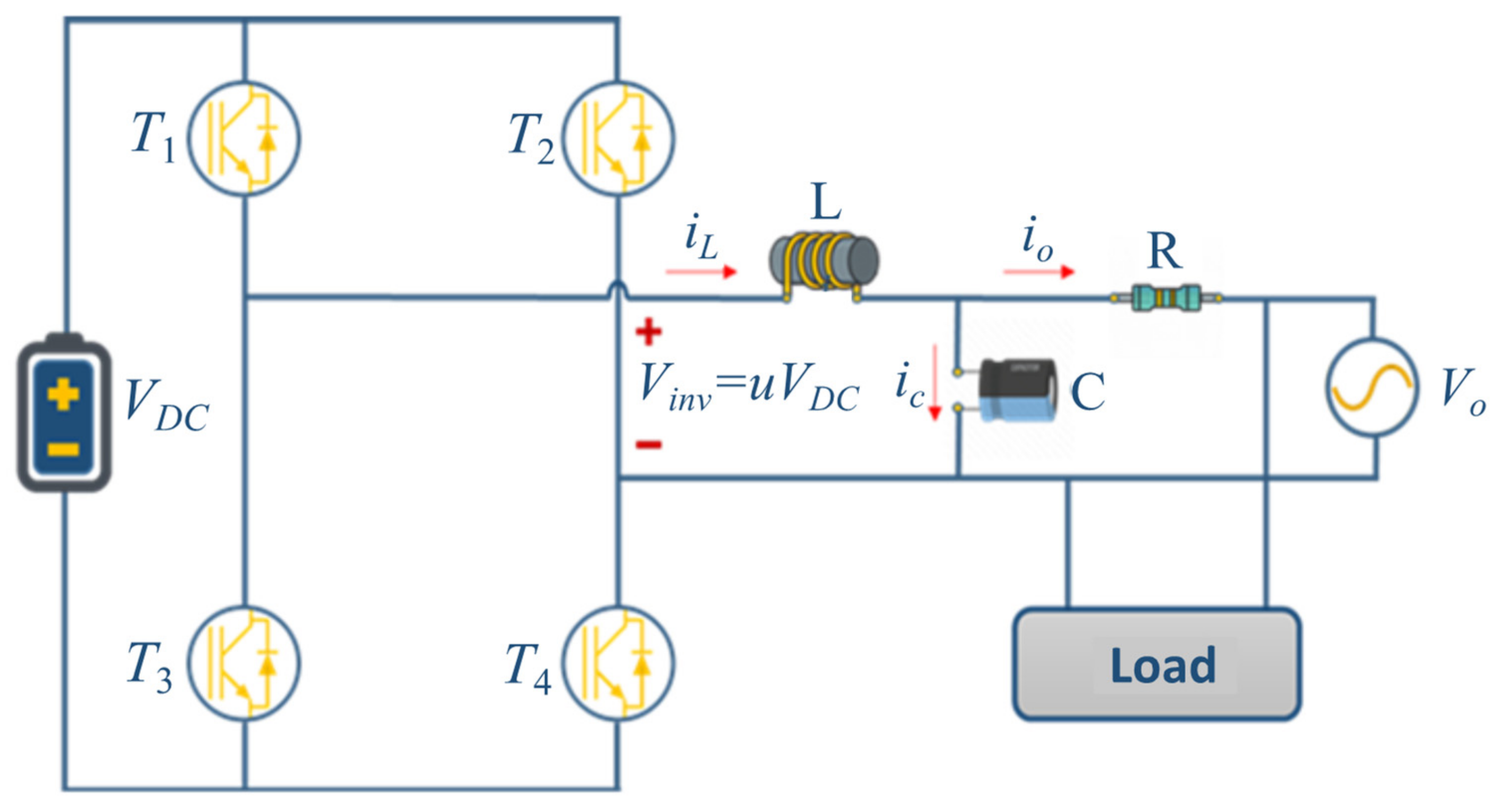
Since the purpose of this paper is to design a control system for an islanded microgrid, we start with the single-phase model of the inverter which is the interface between the DGs and the point of common coupling (PCC) or the loads. Figure 1 shows a typical full-bridge single-phase DC/AC inverter with an inductive-capacitive (LC) filter. This model contains the output LC filter because there is no connection with the main grid.
The main task of the LC filter is to eliminate the harmonic components of the output voltage of the inverter caused by the high frequency switching operation. The full-bridge inverter in Figure 1 consists of four switches divided into two groups. The first group is the combination of and and the second group is the combination of and . The two groups are, respectively, activated so that a sinusoidal output voltage is obtained through the low-pass filter LC. From the Kirchhoff’s laws for voltage and current, the following equation is obtained:
with the state–space representation:
where:
- and denote the inductor current and output voltage, respectively.
- denotes the control signal.
- and are the filter parameters.
- is the voltage of the DC link.
- and are the capacitor current and output current, respectively.
3. Control Strategy
When the microgrid works in the islanding mode, one of its distributed generator units must work as a voltage and frequency regulator. In the sequel, we use a state–space model of the inverter to derive corresponding control algorithms for frequency-voltage control.
3.1. Frequency-Voltage Control in an Islanded Microgrid
To control the voltage and the frequency of the islanded microgrid, we use a hysteresis controller where the error between the reference signal and the output signal is defined as follows:
Let:
a sinusoidal reference signal with amplitude and angular frequency . The is the first derivative of .
By substituting = in (3), we obtain:
By applying Kirchhoff’s law for output current, the following is obtained:
From (2) and (7) we have:
Finally, with =, the system equations are:
with considered to be a system disturbance.
Since the system equations are of second order, then the sliding manifold is defined as follows:
where lambda is a positive number as a control parameter. Sliding manifold occurs when .
The equilibrium surface to reach equilibrium point is calculated by deriving from the sliding manifold:
where is the equilibrium surface.
Equation (12) is used for the sliding manifold and the control signal is defined as:
Equation (13) is applied to the microgrid to control voltage and frequency.
In an islanding microgrid, one of the DGs (DG1) must be operated as a slack generator to control voltage and frequency, and the other DGs (DG2 and DG3) are operated as current control and load sharing. In the next part, an adaptive sliding mode control is designed for the current by control and load sharing between the second and third DGs.
3.2. Current Control and Load Sharing between DGs
In this section, to achieve the load sharing between DG2 and DG3, a current control algorithm based on adaptive sliding mode control is implemented for all three phases, and the gradually obtained control signal (u) is applied to both three-phase inverters (DG2 and DG3).
Following from (2), the output current is:
and put in relation to microgrid sources voltage:
where is the voltage of DG1.
By combining (14) and (15), we have:
If X is defined as difference between the output current and the reference current, then we have:
By substituting (17) in (16), we have:
Now, the (18) is linearized using the Jacobian matrix.
If the initial value is considered zero, , then the linearized form is:
For concise notation, the delta is omitted, and the equation takes the form:
Here and are unknown parameters. It is assumed that x is available and measurable. The observer is used for obtaining and parameters to facilitate the design adaptation laws, in which and are estimation parameters of and , respectively. For this purpose, an observer is formed:
where is the observer gain, and is an estimation value of the x.
The estimation errors of the state and the parameters are denoted with:
Substituting (23) in (22) yields:
By substituting (22) in (24), we obtain:
To make an adaptive law, the following Lyapunov function is evaluated:
where and to ensure the stability, the derivative of the function must be zero:
substituting (25) in (27) gives:
Therefore, the parameter adaptation law is written as follows:
To define the sliding mode controller, we assume
Choosing is proven as practically adequate value of the observer gain to obtain a suitable trade-off of between observer dynamics and accuracy.
The final control law is now obtained with (30) and the observer gain as follows:
We point out the following remarks:
Remark 1.
In Equation (31), if sign(s) is considered in the control law, it causes chattering phenomenon.To prevent this problem, and make a smooth signal, here we use tanh(s) instead of sign(s), as explained in [31].
Remark 2.
By selecting different values of and it is possible to form estimators’ transitions (), i.e., by choosing higher values of and the speed of estimations convergence is faster. However, it may result in high overshooting signal. Selection of the values is therefore a trade-off between speed of convergence and signal overshooting.
4. Simulation Results
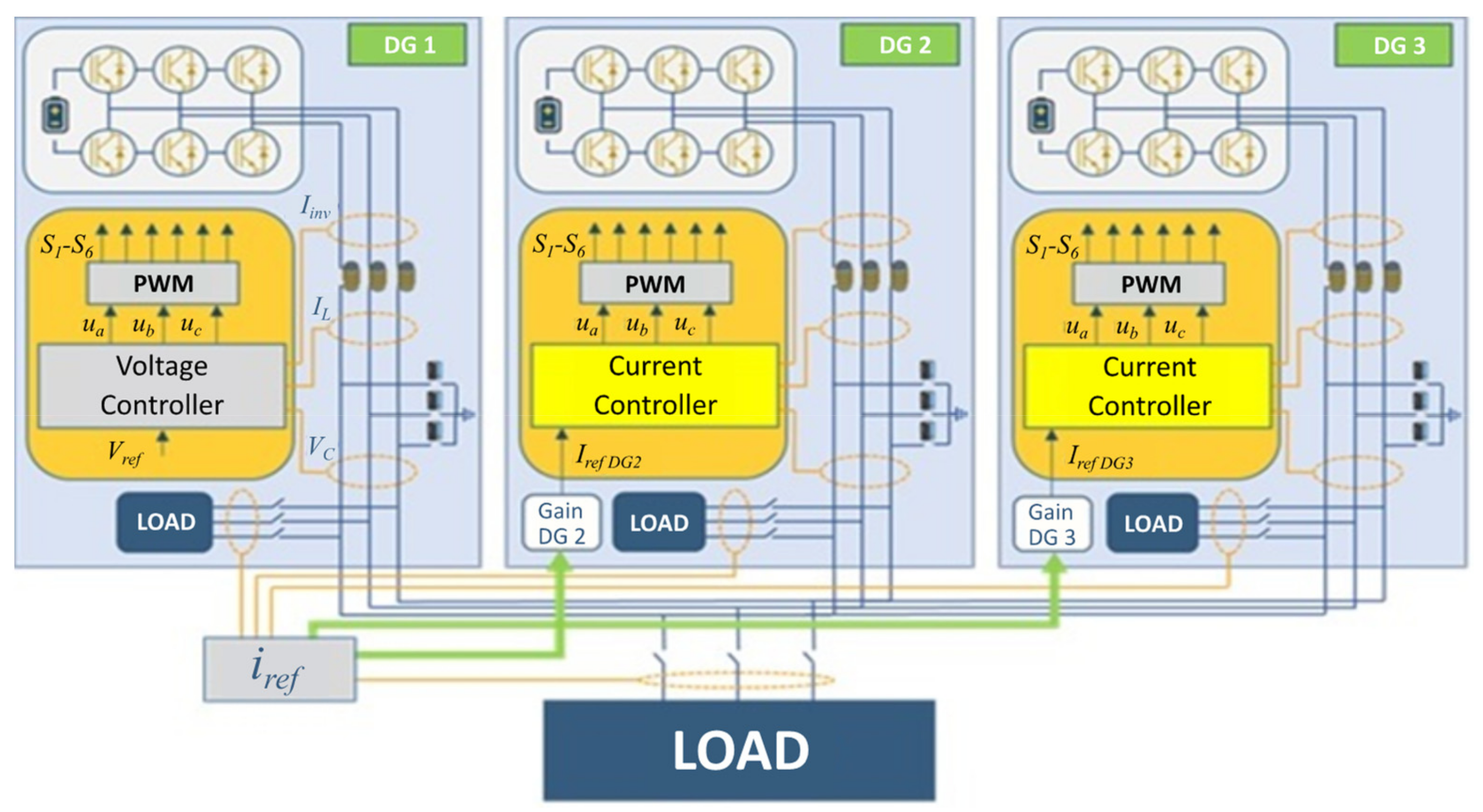
In this section, the proposed control strategy is applied to an islanded microgrid modeled and simulated using the MATLAB/Simulink environment as shown in Figure 2. The proposed control scheme is implemented for all three phases a, b, and c. The values of the control parameters and the distributed generation sources can be found in Table 2. The islanded microgrid consists of three DG units, one of which is considered to be voltage control and the other two as current control. Three scenarios are simulated in which various load types i.e., symmetric, inductive-resistive, and nonlinear loads are studied.
4.1. Scenario 1: Steady State Operation
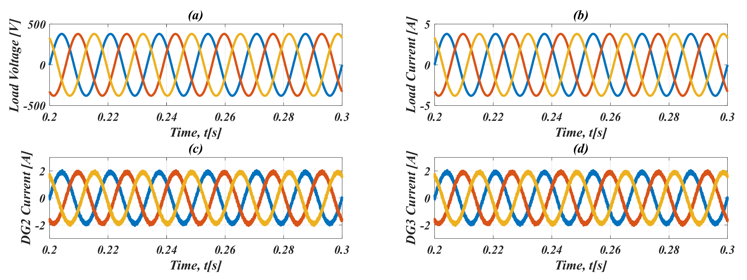
First, to evaluate the steady state operation of the microgrid under the proposed controllers, we applied a constant symmetric resistive load to the microgrid. Table 3 shows the values of the symmetric resistive load. Figure 3 and Figure 4 show the load voltage and current, the DG2 and DG3 currents, and the total harmonic distortion (THD) of the load voltage and current. From Figure 3, it can be seen that the load voltage and current of the microgrid follow their references.
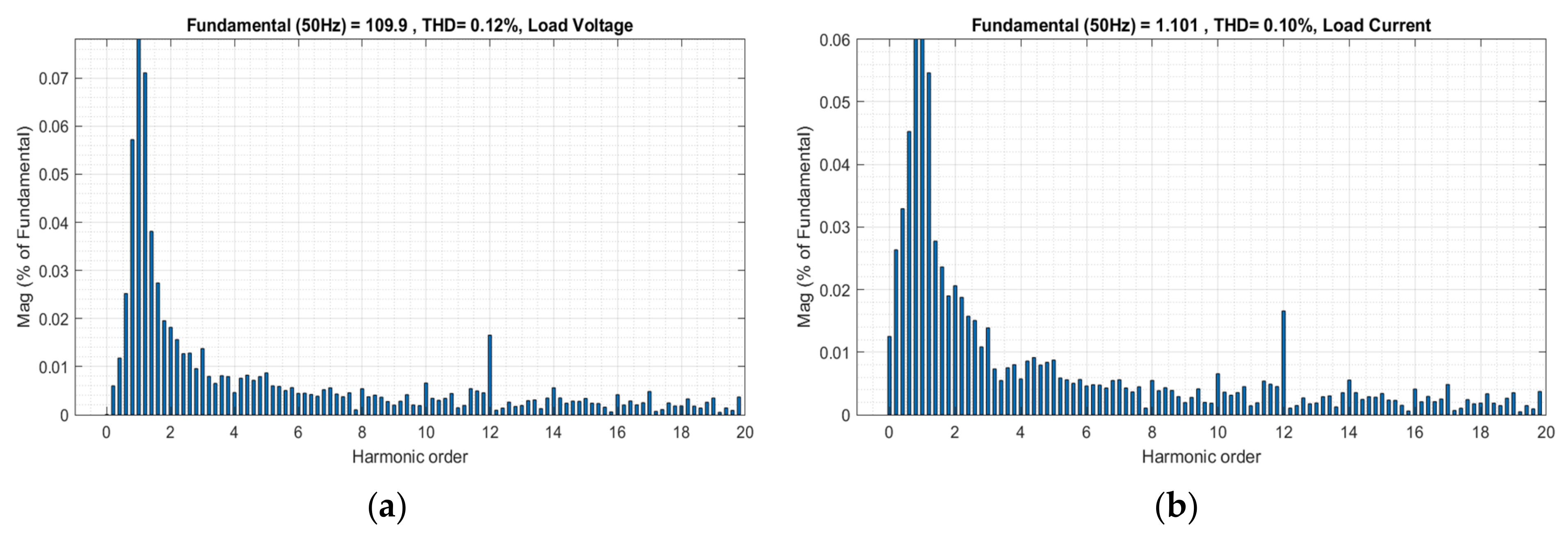
The figure also shows the successful load sharing between DG2 and DG3, each with a half of the load current. Figure 4 shows the total harmonic distortion of the load voltage and current as 0.12% and 0.1%, respectively. According to the IEEE 519 standard for total harmonic distortion [31], the THDs for load voltage and current have acceptable values.
4.2. Scenario 2: Asymmetric Inductive-Resistive Load
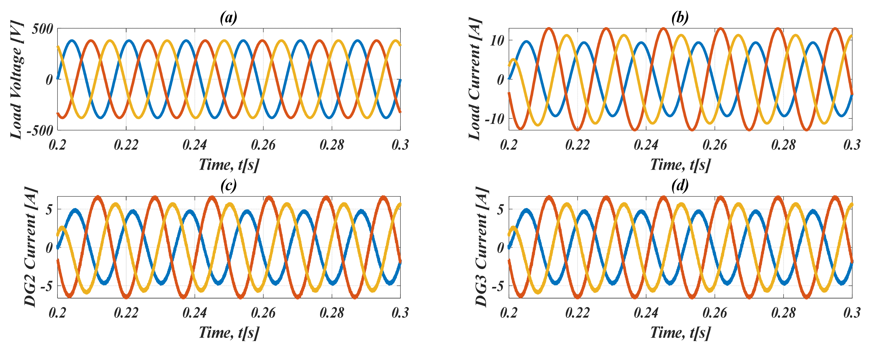
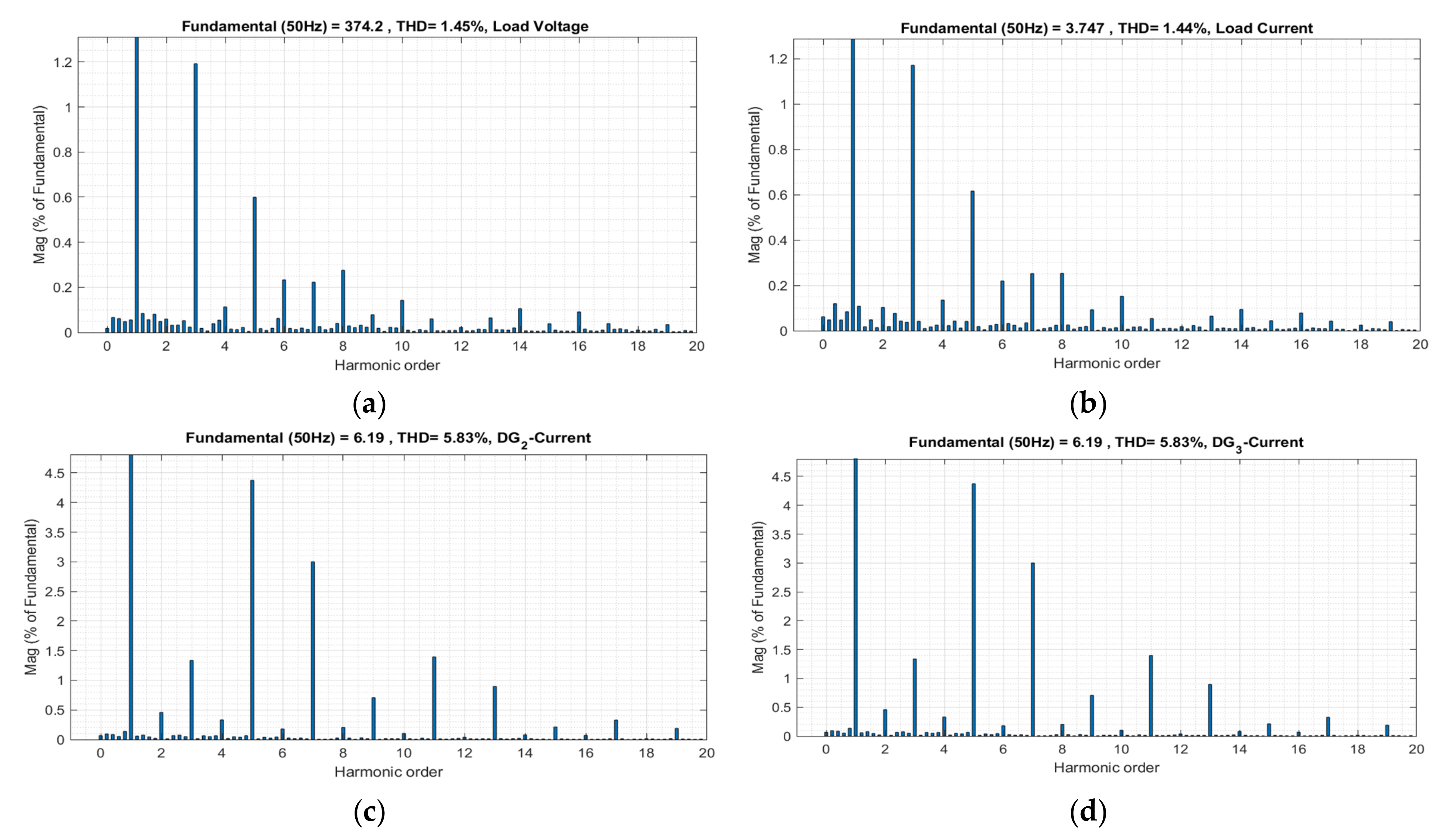
To demonstrate the performance of the proposed controller, in this scenario, the islanded microgrid is loaded with an asymmetric inductive-resistive load. The load parameters are summarized in Table 4. The simulation results are presented in Figure 5 and Figure 6. Figure 5a,b illustrate that the proposed approach can mitigate the effects of inductive loads on the closed-loop AC microgrid. Figure 5c,d show the output current of DG2 and DG3, respectively. From these figures, it can be seen that an inductive-resistive load is added to the primary load at t = 0.2 s. The transient response of the proposed controller is within 10 ms with a slight overshoot, and the control system is robust to load changes. In addition, the (THD) analysis is shown in Figure 6 and THDs have an acceptable value.
4.3. Scenario 3: Nonlinear Load
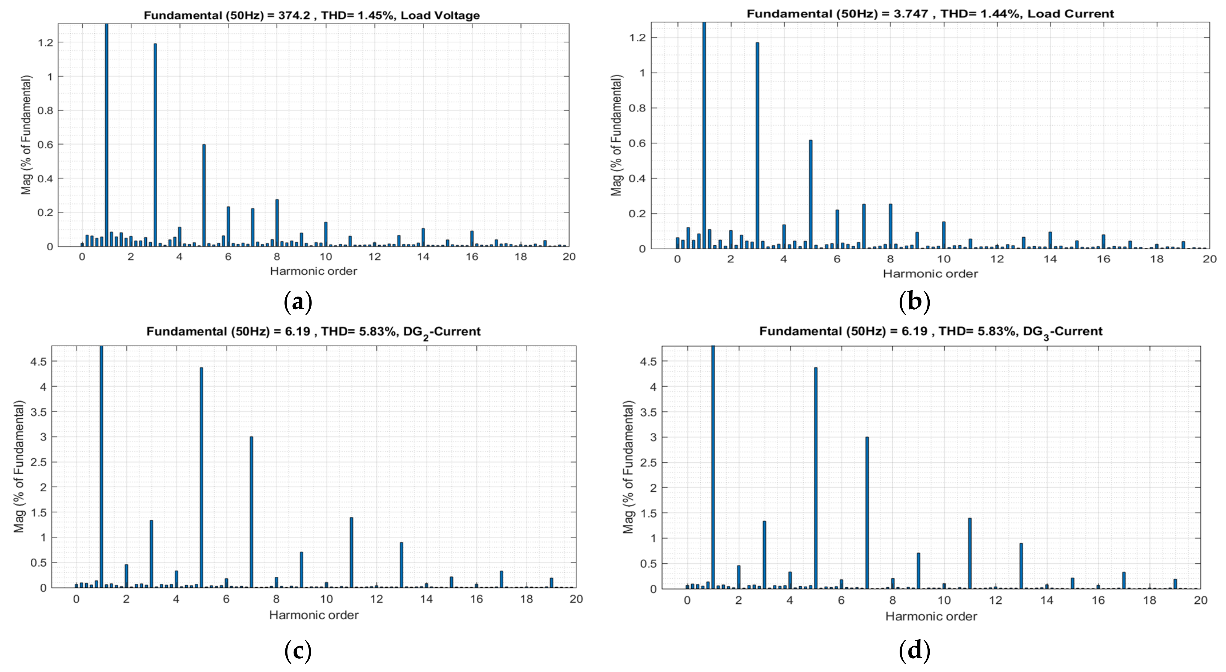
In this section, a nonlinear load is used to verify the performance of the proposed controller. The parameters of this load are summarized in Table 5. The simulation results, for this scenario, are shown in Figure 7 and Figure 8.
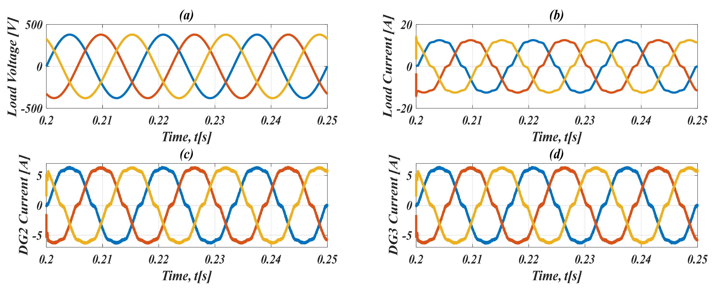
From Figure 7a,b, it can be seen that the desired performance and closed-loop operation of the AC microgrid are achieved after a transient period of less than 2 ms. However, due to the nature of the nonlinear loads, the currents of the microgrid exhibit some distortions that may increase the THD of the system. Figure 7c,d show the waveforms of the output currents of DG2 and DG3 using three regulators during the transient where a nonlinear load is suddenly connected between three parallel inverters. Due to the invariance characteristic of the adaptive sliding mode controller, the output currents of DG2 and DG3 are less sensitive to this transient.
4.4. Comparison between the Proposed Control Strategy and a Conventional Controller
In this section, to show the superiority and effectiveness of the proposed controller, a conventional proportional-integral (PI) controller is designed and applied to the same microgrid with the previous scenarios. The values of the PI control parameters and the microgrid can be found in Table 6.
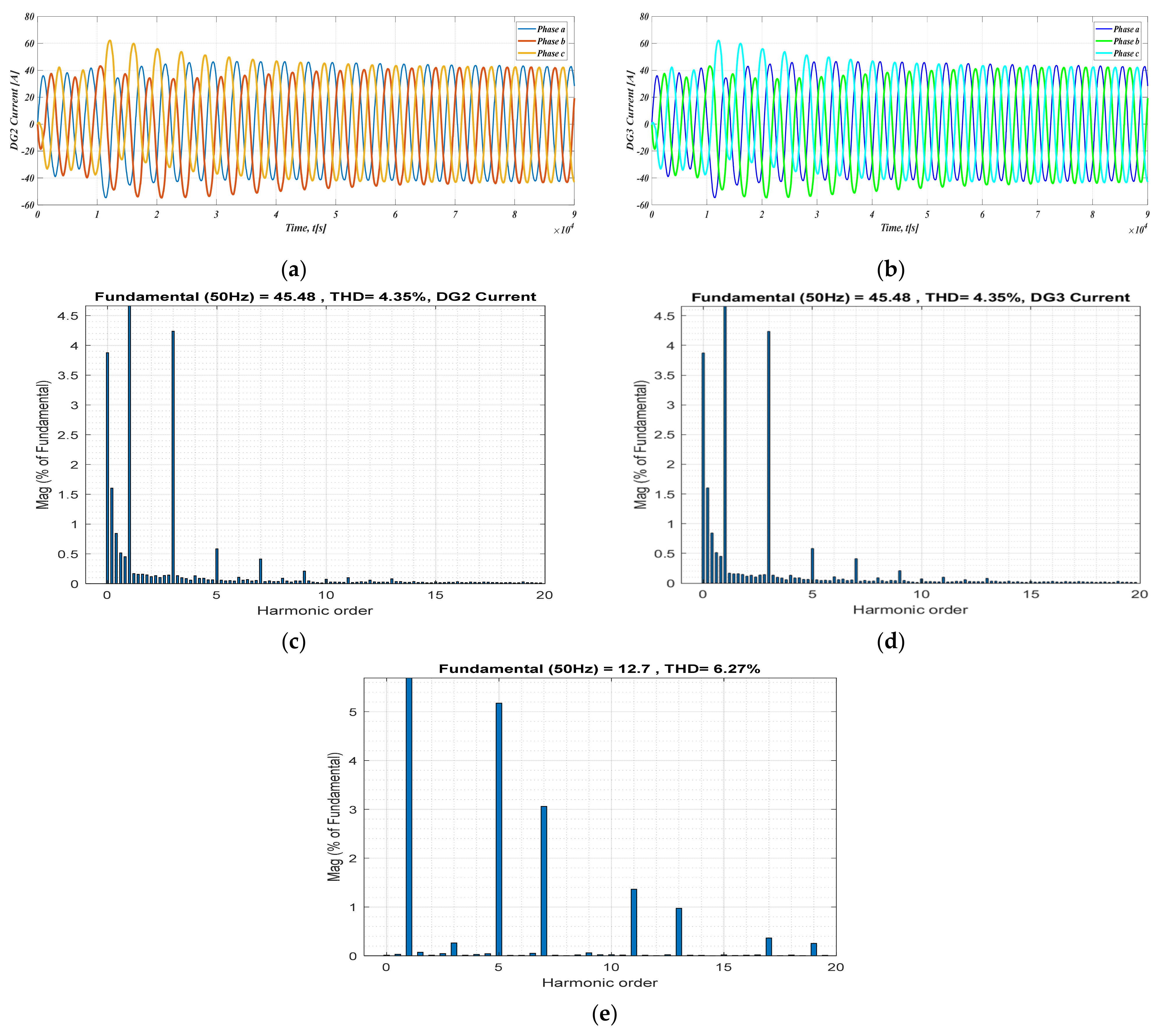
The obtained simulation results from the PI controller are shown in Figure 9. Figure 9a,b shows the currents of DG2 and DG3, respectively. As seen in the figures, it can be noticed that the dynamic response of the PI controller is much slower than the proposed control strategy and it takes approximately 400 ms to settle down. In addition, Figure 9c–e shows the total harmonic distortion of DG2 and DG3 and load current, respectively. In these figures, also it is obvious that THDs with the PI controller is higher than the proposed control method, where the load current THD is increased now from 1.44% to 6.33%.
5. Discussions
To validate the effectiveness of the proposed control strategy, three scenarios were simulated in this paper. In the first scenario, the steady state operation of the microgrid under the proposed controllers is evaluated, in which the constant symmetric resistive load is applied to the microgrid system. The simulation results in Figure 3 shows the successful load sharing between the DG2 and DG3. Figure 4 shows that the THDs for the load voltage and load current is within an acceptable range (0.12% and 0.1% for load voltage and current, respectively), which is less than the reference value according to the IEEE 519 standard for total harmonic distortion [32].
In the second and third scenarios, to examine the proposed control scheme in the transient period the asymmetric inductive-resistive and nonlinear standard IEEE loads are imposed on the microgrid. From Figure 5 and Figure 6, despite applying the asymmetric load to the microgrid, the transient response of the proposed controller is within 10 ms with a slight overshoot. The control system is robust to the load changes, and the THDs analysis have an acceptable value as well, of 1.45% for load voltage and current and 5.83% for DG2 and DG3 currents. Additionally, by applying the IEEE standard nonlinear load, from Figure 7, it is obvious that the desired performance and closed-loop operation of the microgrid is achieved after a transient period of less than 2 ms. In addition, from Figure 7, it can be seen that during the transient where a nonlinear load is suddenly connected between three parallel inverters, the output currents of DG2 and DG3 are less sensitive to this transient, due to the invariance characteristic of the adaptive sliding mode controller.
As another evaluation test, the proposed control method is compared with the conventional PI controller. The conventional PI controller is applied to the same microgrid and following from Figure 9a,b, it is observed that the dynamic response of the PI controller is much slower than the proposed control strategy and the transient time takes approximately 400 ms to settle down, which is 40–200 times slower. Moreover, the analysis of the THDs of DG2 and DG3 and load current in Figure 9c–e show that THDs with PI controller are four times higher than the proposed control scheme.
The simulation results also show that the proposed control method in this research work, in comparison with other similar research work mentioned in the literature, has significant features such as enhanced robustness, effectiveness, stability, fast response, and, above all, simplicity of implementation. For example, in our research work, we used a nonlinear model of the system, and in the model-based control strategy, the control efficacy depends on the accuracy of the model. However, some research works used a linearized model, in which most important information about the system are missed. In comparison to the other work listed in the Introduction, when considering AC microgrids with nonlinear loads, parameter variations or disturbances, nonlinear control approaches are evidently superior to linear ones. Among similar case studies, [16] reports an improvement of the proposed approach over a conventional one by 55.41% for a nonlinear load and 57.29% for an unbalanced load in conducted simulations. In the experiments, the same considered improvements are 16.58% for a nonlinear load and 32.46% for an unbalanced load. In [20], the proposed approach achieves 200 ms settling time for a nonlinear load and simulations conducted on a process with a smaller time constant than ours. In respect to power converter dynamics, the authors in [24] achieve 20 ms settling time in their simulation results. Another sliding mode approach in [30] reports 10 times improvement over a conventional approach. In our case, the settling times were in the range of ms to 10 ms for various scenarios, while comparison with the conventional approach resulted in 40 to 200 times faster response in terms of settling time reduction. In addition, the listed approaches are regularly of higher computational complexity, leading to difficulty of implementation and higher cost, e.g., approaches in [28] and [30] apply transformation of the three-phase coordinate system to a chosen stationary one. This requires real-time calculation of the transformation angle, which is very susceptible to parameter variation and disturbances, and more complex algorithms are required to make the transformation robust. All this proves the potential and superiority of the proposed approach, which as a trade-off, require some practical pre-requisites of more sophisticated, fast-sampling voltage and current sensors that are also often typical for such applications. It is worth noting that a deeper analysis of the specific context for each of the listed approaches is required to obtain a completely fair comparison. Here we provide a tentative analysis as a basis for future observations.
6. Conclusions
This work elaborated voltage and current control and load sharing strategy in an islanded AC microgrid operation. An observer is designed for the adaptation to time-varying nonlinear load and incorporated into sliding mode current controllers. By applying the proposed sliding mode controller, the desired performance of the islanding microgrid in terms of current and voltage regulations and power sharing is improved. The simulation results indicate that the proposed current controller copes well to sudden changes in highly dynamic, asymmetric, and nonlinear load levels and types in the considered AC microgrid. Moreover, the results revealed that the total harmonic distortion is decreased as well in comparison to conventional control system. The designed controller is robust to load changing and stable under different operation conditions and was proved by Lyapunov theory.
Author Contributions
Individual contributions are as follow: Conceptualization, M.H., V.L. and H.I.S.; methodology, M.H., V.L. and P.K.; simulation, M.H.; validation, M.H. and V.L.; formal analysis, M.H., V.L. and P.K.; investigation, M.H., V.L., H.I.S. and P.K.; writing—original draft preparation, M.H., V.L. and H.I.S.; writing—review and editing, M.H., V.L. and H.I.S.; visualization, M.H. and V.L. All authors have read and agreed to the published version of the manuscript.
Funding
This work has been supported in part by Croatian Science Foundation under the project No. UIP-2020-02-9636 (project DECIDE-Distributed Control for Dynamic Energy Management of Complex Systems in Smart Cities). This work has been supported by the European Union from the European Regional Development Fund via Operational Programme Competitiveness and Cohesion 2014–2020 for Croatia through the project Research and development of a unified system for logistic and transport optimisation-Collaborative Elastic and Green Logistics-CEGLog (grant KK.01.2.1.02.0081).
Institutional Review Board Statement
Not applicable.
Informed Consent Statement
Not applicable.
Data Availability Statement
No new data were created or analyzed in this study. Data sharing is not applicable to this article.
Conflicts of Interest
The authors declare no conflict of interest.
Nomenclature
| Inductor current | |
| Capacitor current | |
| Control signal | |
| Filter capacitor | |
| Filter inductor | |
| Filter resistor | |
| Voltage of the DC link | |
| Output voltage | |
| Output current | |
| Output voltage reference | |
| Capacitor current reference | |
| current reference | |
| Amplitude of the reference signal | |
| Maximum current of the distributed generators | |
| Angular frequency | |
| Angular frequency | |
| System disturbance | |
| Sliding manifold | |
| Positive number as a control parameter | |
| Equilibrium surface | |
| Voltage of DG1 | |
| Proportional gain | |
| Integral gain | |
| Control Parameter | |
| Jacobian matrix | |
| Jacobian matrix | |
| Estimation of | |
| Estimation of | |
| Jacobian matrix | |
| Estimation of | |
| Estimation error of | |
| Estimation error of | |
| Estimation error of | |
| Design Parameters |
References
- Delavari, H.; Naderian, S. Design and HIL implementation of a new robust fractional sliding mode control of microgrids. IET Gener. Transm. Distrib. 2021, 14, 6690–6702. [Google Scholar] [CrossRef]
- Elmouatamid, A.; Ouladsine, R.; Bakhouya, M.; El Kamoun, N.; Khaidar, M.; Zine-Dine, K. Review of control and energy management approaches in micro-grid systems. Energies 2021, 14, 168. [Google Scholar] [CrossRef]
- Lee, L.A.; Liu, C.C.; Xu, Y.; Schneider, K.P.; Tuffner, F.K.; Mo, K.; Ton, D.T. Dynamics and control of microgrids as a resiliency source. Int. Trans. Electr. Energ. Syst. 2020, 30, e12610. [Google Scholar] [CrossRef]
- United States Department of Energy, Office of Electricity. Available online: https://www.energy.gov/oe/downloads/smart-grid-introduction-0 (accessed on 15 July 2022).
- Car, M.; Lešić, V.; Vašak, M. Cascaded control of back-to-back converter DC link voltage robust to grid parameters variation. IEEE Trans. Ind. Electron. 2020, 68, 1994–2004. [Google Scholar] [CrossRef]
- Hennane, Y.; Berdai, A.; Pierfederici, S.; Meibody-Tabar, F.; Martin, J.P. Novel non-linear control for synchronization and power sharing in islanded and grid-connected mesh microgrids. Electr. Power Syst. Res. 2022, 208, 107869. [Google Scholar] [CrossRef]
- Peyghami, S.; Davari, P.; Mokhtari, H.; Blaabjerg, F. Decentralized droop control in DC microgrids based on a frequency injection approach. IEEE Trans. Smart Grid 2019, 10, 6782–6791. [Google Scholar] [CrossRef]
- Rocabert, J.; Luna, A.; Blaabjerg, A.; Rodriguez, P. Control of power converters in AC microgrids. IEEE Trans. Ind. Electron. 2012, 27, 4734–4749. [Google Scholar] [CrossRef]
- Azarm, V.; Hajihosseini, M.; Farjah, E.; Ghanbari, T. A suitable controller for load sharing between paralleled inverters of an islanded microgrid. In Proceedings of the 2017 Iranian Conference on Electrical Engineering (ICEE), Tehran, Iran, 2–4 May 2017; pp. 1400–1405. [Google Scholar] [CrossRef]
- Katiraei, F.; Iravani, R.; Hatziargyriou, N.; Dimeas, A. Microgrids management. IEEE Power Energy Mag. 2008, 6, 54–65. [Google Scholar] [CrossRef]
- Baghaee, H.R.; Mirsalim, M.; Gharehpetian, G.B.; Talebi, H.A. Decentralized sliding mode control of WG/PV/FC microgrids under unbalanced and nonlinear load conditions for on-and off-grid modes. IEEE Syst. J. 2017, 12, 3108–3119. [Google Scholar] [CrossRef]
- Zhang, M.; Song, B.; Wang, J. Circulating current control strategy based on equivalent feeder for parallel inverters in islanded microgrid. IEEE Trans. Power Syst. 2018, 34, 595–605. [Google Scholar] [CrossRef]
- Bagheri, R.T.; Fakharian, A. Robust Control of Islanded DC Microgrid for Voltage Regulation Based on Polytopic Model and Load Sharing. Iran. J. Sci. Technol.-Trans. Electr. Eng. 2022, 46, 171–186. [Google Scholar] [CrossRef]
- Golsorkhi, M.S.; Hill, D.J.; Baharizadeh, M. A secondary control method for voltage unbalance compensation and accurate Load sharing in networked microgrids. IEEE Trans. Smart Grid 2021, 12, 2822–2833. [Google Scholar] [CrossRef]
- Car, M.; Lešić, V.; Vašak, M. DC link voltage control of back-to-back converter robust to grid conditions. In Proceedings of the 2017 19th International Conference on Electrical Drives and Power Electronics (EDPE), Dubrovnik, Croatia, 4–6 October 2017; pp. 147–152. [Google Scholar] [CrossRef]
- Vijay, A.S.; Parth, N.; Doolla, S.; Chandorkar, M.C. An adaptive virtual impedance control for improving power sharing among inverters in islanded AC microgrids. IEEE Trans. Smart Grid 2021, 12, 2991–3003. [Google Scholar] [CrossRef]
- Wang, X.; Guerrero, J.M.; Chen, Z. Control of grid interactive AC microgrids. In Proceedings of the 2010 IEEE International Symposium on Industrial Electronics, Bari, Italy, 4–7 July 2010; pp. 2211–2216. [Google Scholar] [CrossRef]
- Zhong, Q.C. Robust droop controller for accurate proportional load sharing among inverters operated in parallel. IEEE Trans. Ind. Electron. 2011, 60, 1281–1290. [Google Scholar] [CrossRef]
- Meng, W.; Wang, X.; Liu, S. Distributed load sharing of an inverter-based microgrid with reduced communication. IEEE Trans. Smart Grid 2016, 9, 1354–1364. [Google Scholar] [CrossRef]
- Ghanbarian, M.M.; Nayeripour, M.; Rajaei, A.; Mansouri, M.M. Design and implementation of a new modified sliding mode controller for grid-connected inverter to controlling the voltage and frequency. ISA Trans. 2016, 61, 179–187. [Google Scholar] [CrossRef]
- Tuladhar, A.; Jin, H.; Unger, T.; Mauch, K. Control of parallel inverters in distributed AC power systems with consideration of line impedance effect. IEEE Trans. Ind. Appl. 2000, 36, 131–138. [Google Scholar] [CrossRef]
- Canciello, G.; Cavallo, A.; Cucuzzella, M.; Ferrara, A. Fuzzy scheduling of robust controllers for islanded DC microgrids applications. Int. J. Dyn. Control 2019, 7, 690–700. [Google Scholar] [CrossRef]
- Hajihosseini, M.; Abedi, A.A.; Nakhaei, N.; Hajihosseini, M.H. Intelligent Control Frequency Microgrid in Islanded Mode by Central Protection Unit. Cienc. Nat. 2015, 37, 205–213. [Google Scholar] [CrossRef]
- Avila-Becerril, S.; Espinosa-Pérez, G. Control of islanded microgrids considering power converter dynamics. Int. J. Control 2021, 94, 2520–2530. [Google Scholar] [CrossRef]
- Kumar, J.; Agarwal, A.; Agarwal, V. A review on overall control of DC microgrids. J. Energy Storage 2019, 21, 113–138. [Google Scholar] [CrossRef]
- Suleiman, H.U.; Mu’azu, M.B.; Zarma, T.A.; Salawudeen, A.T.; Thomas, S.; Galadima, A.A. Methods of chattering reduction in sliding mode control: A case study of ball and plate system. In Proceedings of the 2018 IEEE 7th international Conference on Adaptive Science & Technology (ICAST), Accra, Ghana, 22–24 August 2018; pp. 1–8. [Google Scholar] [CrossRef]
- Arranz-Gimon, A.; Zorita-Lamadrid, A.; Morinigo-Sotelo, D.; Duque-Perez, O. A review of total harmonic distortion factors for the measurement of harmonic and interharmonic pollution in modern power systems. Energies 2021, 14, 6467. [Google Scholar] [CrossRef]
- Shah, A.A.; Han, X.; Armghan, H.; Almani, A.A. A Nonlinear Integral Backstepping Controller to Regulate the Voltage and Frequency of an Islanded Microgrid Inverter. Electronics 2021, 10, 660. [Google Scholar] [CrossRef]
- Yang, C.; Ni, S.; Dai, Y.; Huang, X.; Zhang, D. Anti-Disturbance Finite-Time Adaptive Sliding Mode Backstepping Control for PV Inverter in Master–Slave-Organized Islanded Microgrid. Energies 2020, 13, 4490. [Google Scholar] [CrossRef]
- Rashad, M.; Raoof, U.; Siddique, N.; Ahmed, B.A. Equivalent Sliding Mode Controller for Stability of DC Microgrid. Eng. Proc. 2021, 12, 23. [Google Scholar] [CrossRef]
- Khan, M.Z.; Mu, C.; Habib, S.; Hashmi, K.; Ahmed, E.M.; Alhosaini, W. An Optimal Control Scheme for Load Bus Voltage Regulation and Reactive Power-Sharing in an Islanded Microgrid. Energies 2021, 14, 6490. [Google Scholar] [CrossRef]
- Armghan, A.; Hassan, M.; Armghan, H.; Yang, M.; Alenezi, F.; Azeem, M.K.; Ali, N. Barrier Function Based Adaptive Sliding Mode Controller for a Hybrid AC/DC Microgrid Involving Multiple Renewables. Appl. Sci. 2021, 11, 8672. [Google Scholar] [CrossRef]
Figure 1.
DC/AC Inverter Scheme with an LC Filter.

Figure 2.
Island Microgrid.

Figure 3.
Load and Current waves in Steady State Operation: (a) Load Voltage, (b) Load current, (c) DG2 Current, (d) DG3 Current.
Figure 3.
Load and Current waves in Steady State Operation: (a) Load Voltage, (b) Load current, (c) DG2 Current, (d) DG3 Current.

Figure 4.
Load Voltage and Current THD Analyzing in Steady State Operation: (a) the THD of the Load Voltage, (b) the THD of the Current Load.
Figure 4.
Load Voltage and Current THD Analyzing in Steady State Operation: (a) the THD of the Load Voltage, (b) the THD of the Current Load.

Figure 5.
Load and Current Waves in Transient Operation Under Asymmetric Inductive-Resistive Load: (a) Load Voltage, (b) Load current, (c) DG2 Current, (d) DG3 Current.
Figure 5.
Load and Current Waves in Transient Operation Under Asymmetric Inductive-Resistive Load: (a) Load Voltage, (b) Load current, (c) DG2 Current, (d) DG3 Current.

Figure 6.
Load Voltage and Current THD Analyzing Under Asymmetric Inductive-Resistive Load: (a) the THD of the Load Voltage, (b) the THD of the Current Load, (c) the THD of the DG2, (d) the THD of the DG3.
Figure 6.
Load Voltage and Current THD Analyzing Under Asymmetric Inductive-Resistive Load: (a) the THD of the Load Voltage, (b) the THD of the Current Load, (c) the THD of the DG2, (d) the THD of the DG3.

Figure 7.
Load and Current Waves in Transient Operation Under Non-linear Load: (a) Load Voltage, (b) Load current, (c) DG2 Current, (d) DG3 Current.
Figure 7.
Load and Current Waves in Transient Operation Under Non-linear Load: (a) Load Voltage, (b) Load current, (c) DG2 Current, (d) DG3 Current.

Figure 8.
Load Voltage and Current THD Analyzing Under Nonlinear Load: (a) the THD of the Load Voltage, (b) the THD of the Current Load, (c) the THD of the DG2, (d) the THD of the DG3.
Figure 8.
Load Voltage and Current THD Analyzing Under Nonlinear Load: (a) the THD of the Load Voltage, (b) the THD of the Current Load, (c) the THD of the DG2, (d) the THD of the DG3.

Figure 9.
PI Controller system in Steady State Operation, (a) the Current of DG2, (b) the Current of DG3, (c) the THD analysis of the Load Current, (d) the THD analysis of DG2, (e) the THD analysis of the Load Current.
Figure 9.
PI Controller system in Steady State Operation, (a) the Current of DG2, (b) the Current of DG3, (c) the THD analysis of the Load Current, (d) the THD analysis of DG2, (e) the THD analysis of the Load Current.


Table 1.
Summary of different control methods for MGs in the literature focused on the considered problem.
Table 1.
Summary of different control methods for MGs in the literature focused on the considered problem.
| Control Structure | Linear/Nonlinear | Microgrid Type | Parameters Variation | Disturbances | Referenced in |
|---|---|---|---|---|---|
| Nominal transfer function | Linear | AC Microgrid | Yes | Yes | [15] |
| Adaptive decentralized technique for adjusting the virtual impedance | Nonlinear | AC Microgrid | Yes | Yes | [16] |
| Improved droop control | Linear | AC Microgrids | Yes | Yes | [18] |
| Distributed control approach | Linear | AC Microgrids | No | No | [19] |
| Modified sliding mode controller | Nonlinear | AC Microgrids | Yes | Yes | [20] |
| Frequency droop control | Linear | AC Microgrids | Yes | No | [21] |
| Third order sliding mode algorithm and a high-gain controller with a fuzzy scheduling | Nonlinear | DC Microgrid | Yes | Yes | [22] |
| Intelligent droop control | Linear | AC Microgrids | Yes | Yes | [23] |
| Passivity-based controller for a Port-controlled Hamiltonian | Linear | AC Microgrids | Yes | Yes | [25] |
| Decentralized nonlinear integral backstepping | Nonlinear | AC Microgrids | Yes | Yes | [26] |
| Finite-time adaptive sliding mode backstepping | Nonlinear | AC/DC Microgrids | Yes | Yes | [27] |
| Equivalent sliding mode | Linear | DC Microgrids | No | No | [28] |
| Optimal stochastic | Linear | AC Microgrids | No | No | [29] |
| Adaptive Sliding Mode | Nonlinear | AC/DC microgrid | Yes | Yes | [30] |
Table 2.
Values of Distributed Generation Source and Control Parameters.
| Symbol | Definition | Value | Unit |
|---|---|---|---|
| DC Voltage Value | 800 V | Voltage Control Unit (DG1) | |
| Angular Frequency | 314.16 rad/s | ||
| Filter Inductor | 11 mH | ||
| Filter Capacitor | 220 µH | ||
| Control Parameter | 20,000 | ||
| Switching Frequency | 15,000 Hz | ||
| Reference Voltage Amplitude | 380 V | ||
| DC Voltage Value | 800 V | Current Control and Load Sharing Units (DG2, DG3) | |
| Filter Inductor | 11 mH | ||
| Filter Capacitor | 220 µH | ||
| Control Parameter | 10,000 | ||
| Maximum Current of Each Unit | 15 A |
Table 3.
Symmetric Resistive Load Parameters.
| Primary Load | |
|---|---|
| Phase a | |
| Phase b | |
| Phase c |
Table 4.
Asymmetric Inductive-Resistive Load Parameter.
| Primary Load | Secondary Load | ||
|---|---|---|---|
| Phase a | |||
| Phase b | |||
| Phase c | |||
Table 5.
Nonlinear Load Parameters.
| Primary Load | Secondary Load | ||
|---|---|---|---|
| Phase a | |||
| Phase b | |||
| Phase c | |||
Table 6.
Values of Distributed Generation Sources and PI Control Parameters.
| Symbol | Definition | Value | Unit |
|---|---|---|---|
| DC Voltage Value | 800 V | Voltage Control Unit (DG1) | |
| Angular Frequency | 314.16 rad/s | ||
| Filter Inductor | 11 mH | ||
| Filter Capacitor | 220 µF | ||
| Control Parameter | 20,000 | ||
| Switching Frequency | 15,000 Hz | ||
| Reference Voltage Amplitude | 380 V | ||
| DC Voltage Value | 800 V | Current Control and Load Sharing Unit (DG2, DG3) | |
| Filter Inductor | 11 mH | ||
| Filter Capacitor | 220 µF | ||
| Proportional Gain | 0.001 | ||
| Integral Gain | 0.1 |
Publisher’s Note: MDPI stays neutral with regard to jurisdictional claims in published maps and institutional affiliations. |
© 2022 by the authors. Licensee MDPI, Basel, Switzerland. This article is an open access article distributed under the terms and conditions of the Creative Commons Attribution (CC BY) license (https://creativecommons.org/licenses/by/4.0/).
Share and Cite
MDPI and ACS Style
Hajihosseini, M.; Lešić, V.; Shaheen, H.I.; Karimaghaee, P. Sliding Mode Controller for Parameter-Variable Load Sharing in Islanded AC Microgrid. Energies 2022, 15, 6029. https://0-doi-org.brum.beds.ac.uk/10.3390/en15166029
AMA Style
Hajihosseini M, Lešić V, Shaheen HI, Karimaghaee P. Sliding Mode Controller for Parameter-Variable Load Sharing in Islanded AC Microgrid. Energies. 2022; 15(16):6029. https://0-doi-org.brum.beds.ac.uk/10.3390/en15166029
Chicago/Turabian StyleHajihosseini, Mojtaba, Vinko Lešić, Husam I. Shaheen, and Paknoosh Karimaghaee. 2022. "Sliding Mode Controller for Parameter-Variable Load Sharing in Islanded AC Microgrid" Energies 15, no. 16: 6029. https://0-doi-org.brum.beds.ac.uk/10.3390/en15166029
Note that from the first issue of 2016, this journal uses article numbers instead of page numbers. See further details here.