Article

Comparison and Parametric Analysis of Thermoelectric Generator System for Industrial Waste Heat Recovery with Three Types of Heat Sinks: Numerical Study

School of Mechanical Engineering, Yeungnam University, 280 Daehak-ro, Gyeongsan-si 38541, Gyeongsangbuk-do, Korea
*
Author to whom correspondence should be addressed.
Submission received: 11 August 2022 / Revised: 25 August 2022 / Accepted: 28 August 2022 / Published: 30 August 2022
(This article belongs to the Special Issue Advanced Techniques for Thermoelectric Generator and Fuel Cell System)

Abstract

:
In this study, a fluid–thermal–electrical multiphysics numerical model was developed for the thermal and electrical analyses of a heat sink-based thermoelectric generator (TEG) in a waste heat recovery system used for casting a bronze ingot mold. Moreover, the model was validated based on experimental data. Heat sinks were installed on the hot side of the TEG module to recover the waste heat from the flue gas generated in the casting process. The numerical results of the thermal and electrical characteristics of a plate fin (PF)-based TEG showed good agreement with the experimental findings. Numerical simulations of heat sinks with three different fin structures—PF, cylinder pin fin (CPF), and rectangular pin fin (RPF)—were conducted. The simulated system pressure drop, hot- and cold-side temperature difference in the TEG module, TEG power output, and TEG efficiency were compared for the differently designed fin structures. The results showed that for the same fin area, the CPF heat sink-based TEG system achieved a lower pressure drop, higher power output, and higher efficiency than the other two designs. This was particularly true when the velocity of the flue gas and the fin height exceed 5 m/s and 28.6 mm, respectively. Therefore, for low and high flue gas velocities, PF and CPF heat sinks are recommended as the best choices, respectively.

1. Introduction

Reducing energy waste and improving energy efficiency have become significant challenges worldwide [1]. Waste heat recovery (WHR) plays a very important role as an energy saving and emission gas reduction approach [2]. Approximately 52% of global energy consumption (474 PJ) is wasted through exhaust gases and effluents, out of which 22% of the waste heat is produced by industry, resulting in inefficient and uneconomical industrial facilities [3]. Various WHR systems, such as heat wheels, recuperators, air preheaters, regenerators, and waste heat boilers are employed to improve the performance of industrial facilities. They capture and transfer the waste heat from an industrial process, which is further used either in the industrial process itself or for power generation. However, most WHR systems are highly complex and employ various thermodynamic cycles; therefore, they have not been utilized in some industrial applications [4]. Thermoelectric generators (TEGs) have many advantages, including reliability and an absence of noise, chemical reactions, and moving parts. Moreover, they have good potential in applications converting waste thermal energy to electrical energy to improve overall energy efficiency [5].
A TEG system is a solid-state device that consists of p- and n-type semiconductors forming an electric circuit and converting heat flow into electric power through the Seebeck effect, while operating under a temperature differential [6]. TEGs which improve the efficiency of energy utilization have many practical applications, ranging from heat utilization in microelectronics to large-scale thermal power plant WHR, and from renewable energy to traditional industrial waste heat [7,8].
Numerous studies have been conducted that consider a TEG as a WHR system for vehicle exhaust [9,10,11,12]. In addition to industrial products such as vehicle exhaust systems, industrial processes account for a large amount of waste heat during flue gas exhaustion and product manufacturing. Therefore, numerous studies have been conducted to recover waste heat from exhaust effluents [1,13] and during product manufacturing [14,15] using a TEG-based WHR system.
Investigations have also been conducted to augment the efficiency of TEG-based heat-recovery systems. The efficiency of thermoelectric energy conversion depends on the performance of the thermoelectric materials and devices [16]. Several studies have analyzed the performance outputs of various TEG materials [17,18,19]. However, exploration of high-performance thermoelectric materials alone is insufficient for improving WHR systems utilizing a TEG; a structure-based approach is also required to enhance the performance of WHR systems [20]. Therefore, several studies have focused on enhancing the heat transfer performance of WHR systems using different designs of heat spreaders, heat exchangers, heat absorbers, and heat sinks [21,22]. However, a heat sink is typically preferred because of its cost-effectiveness, easy manufacture and installation, and its enhancement of the heat flux density of TEG-based WHR systems [23]. In this study, a TEG system was being used to recover the waste heat from a bronze ingot casting process in Korea. A standard type of rectangular plate fin (PF) heat sink was installed on the hot side of the TEG to recover the waste heat from a casting mold, with the flow direction of the flue gas normal to the fin base. However, to improve the efficiency of the system, the effects of heat sinks with different fin types on the system performance should be tested.
Many studies have been conducted on integrating a heat sink with a TEG to improve the TEG performance. Lv et al. [5] compared three different cooling methods used on the cold side of a TEG. Lower auxiliary power consumption was achieved using a heat sink compared to systems with two other cooling methods: a heat pipe and a water-cooled heat exchanger. Wang et al. [24] optimized a heat sink on the cold side of a TEG using numerical analysis to improve the performance of the system. The results demonstrated that using an optimized design of the heat sink increased the power output of the TEG system by 88.7%. Rezania and Rosendahl [25] compared a micro-structured plate fin heat sink with a modified design of a cross-cut heat sink on the cold side of a TEG using a numerical method. The results indicated that a higher maximum net power generation was obtained from the TEG using the PF and cross-cut heat sinks with lower and higher flow inlet velocities, respectively. Nayak et al. [26] developed a numerical (computational fluid dynamics (CFD)) model of a solar-assisted TEG system with a plate heat sink on the cold side. Based on the CFD simulations, the maximum limiting heat flux was found with the heat sink positioned at a 30° attack angle and with a 5 m/s wind velocity. Zheng and Kang [27] developed a passive evaporative cooling heat sink to enhance the capacity of the WHR of a TEG. They showed that their novel heat sink has significant potential for use in a TEG-based WHR system as a cooling device. Heat sinks have also been used on the hot side of a TEG for WHR. Luo et al. [6] optimized the design of a TEG module for WHR from flow gases using a heat sink on the hot side. Luo et al. [5] also analyzed the performance of a TEG-based WHR system integrated with a heat sink on the hot side using two different models. They found that the numerical model was more accurate than the thermal resistance model for the performance analysis of the TEG. In another study [1], a PF heat sink integrated on the hot side of a TEG was investigated in a performance evaluation of a WHR system using different flow and fin parameters to recover the waste heat from chimney exhaust.
In the literature cited above, most studies use heat sinks on the cold side of a TEG as cooling devices [5,24,25,26,27], whereas investigations on the use of heat sinks on the hot side are limited [6,13]. Moreover, in most of these investigations [4,5,6,13,24,25,26,27], the heat flow was along the heat sink surface; i.e., parallel to the heat sink base. No study was found on the performance of a system using an impingement heat flow to a heat sink on the hot side of a TEG. Moreover, studies considering the effects of different heat sink fin types, particularly in a TEG-based WHR system, are scarce.
To overcome the aforementioned limitations, in this study, a three-dimensional (3D) multiphysics numerical investigation was conducted using plate fin (PF), cylinder pin fin (CPF), and rectangular pin fin (RPF) heat sinks on the hot side of a TEG system. The TEG system studied recovers the waste heat from the bronze ingot casting process, with the heat flow being along the fin height, normal to the fin base of the heat sink. The performance of the TEG-based WHR system was evaluated in terms of the system pressure drop, hot- and cold-side temperature difference in the TEG module, TEG power output, and TEG efficiency. Comparison of the simulation results for the three different heat sinks provided a reasonable solution for the selection of heat sinks under various working conditions.

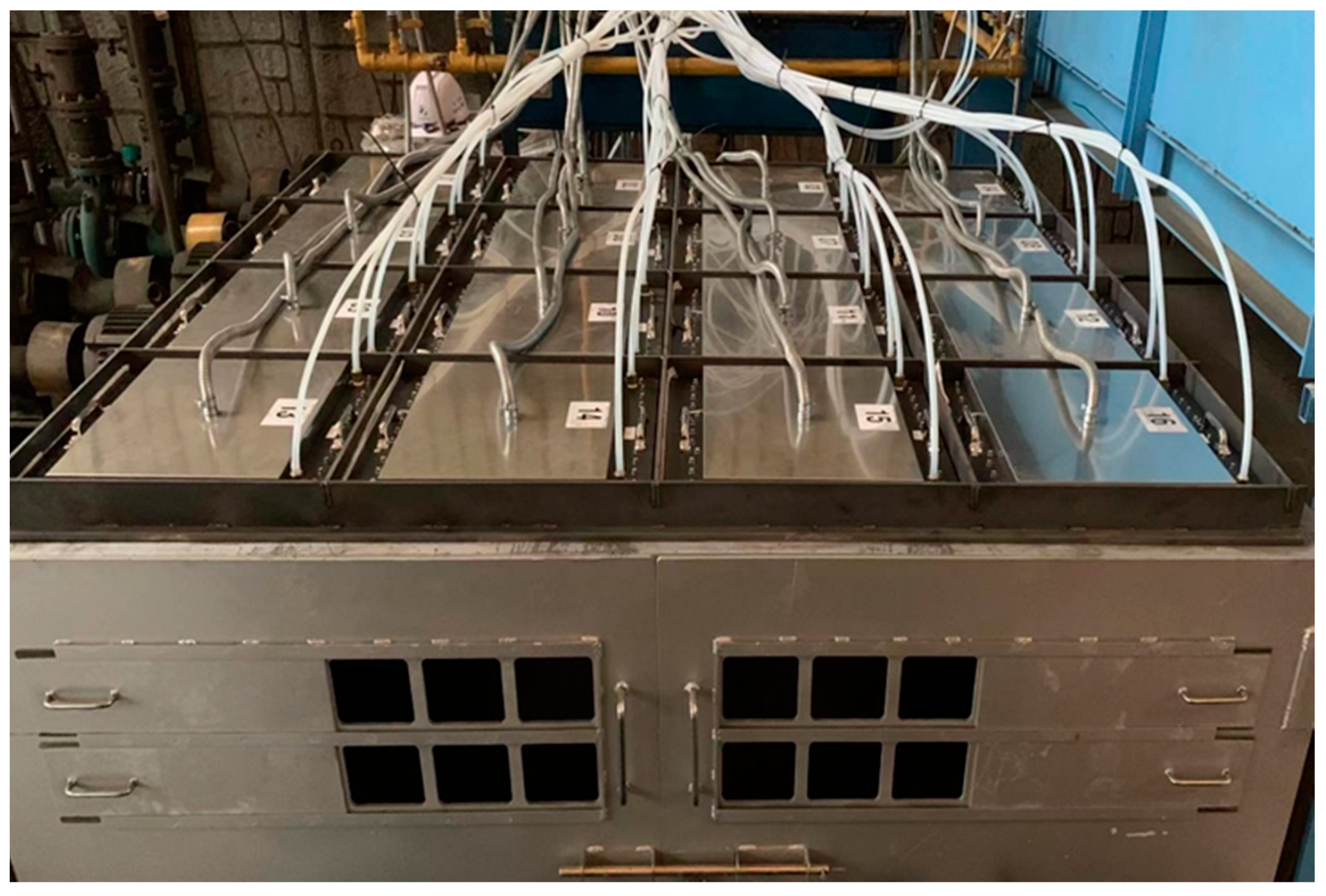
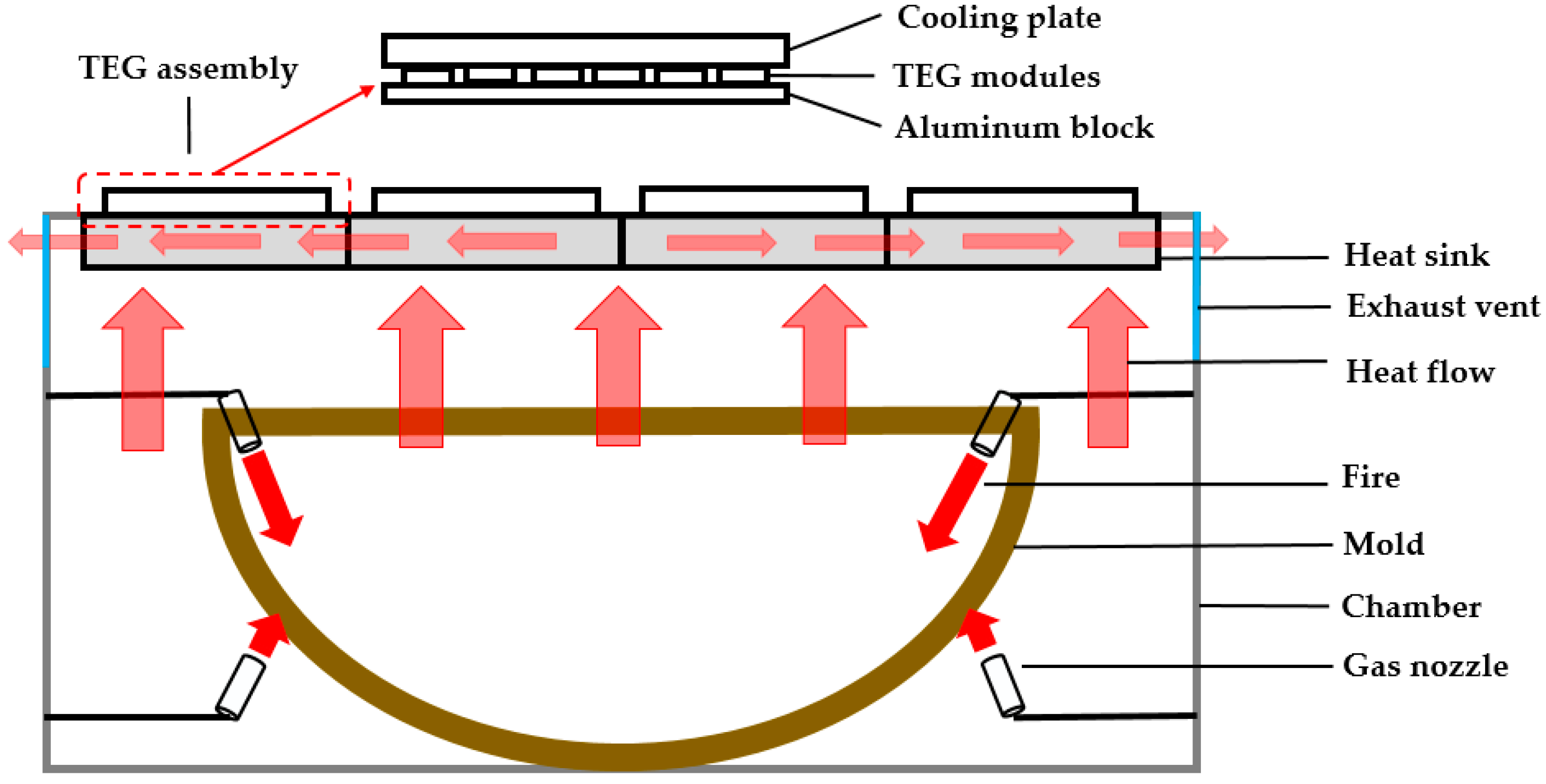
2. System Description
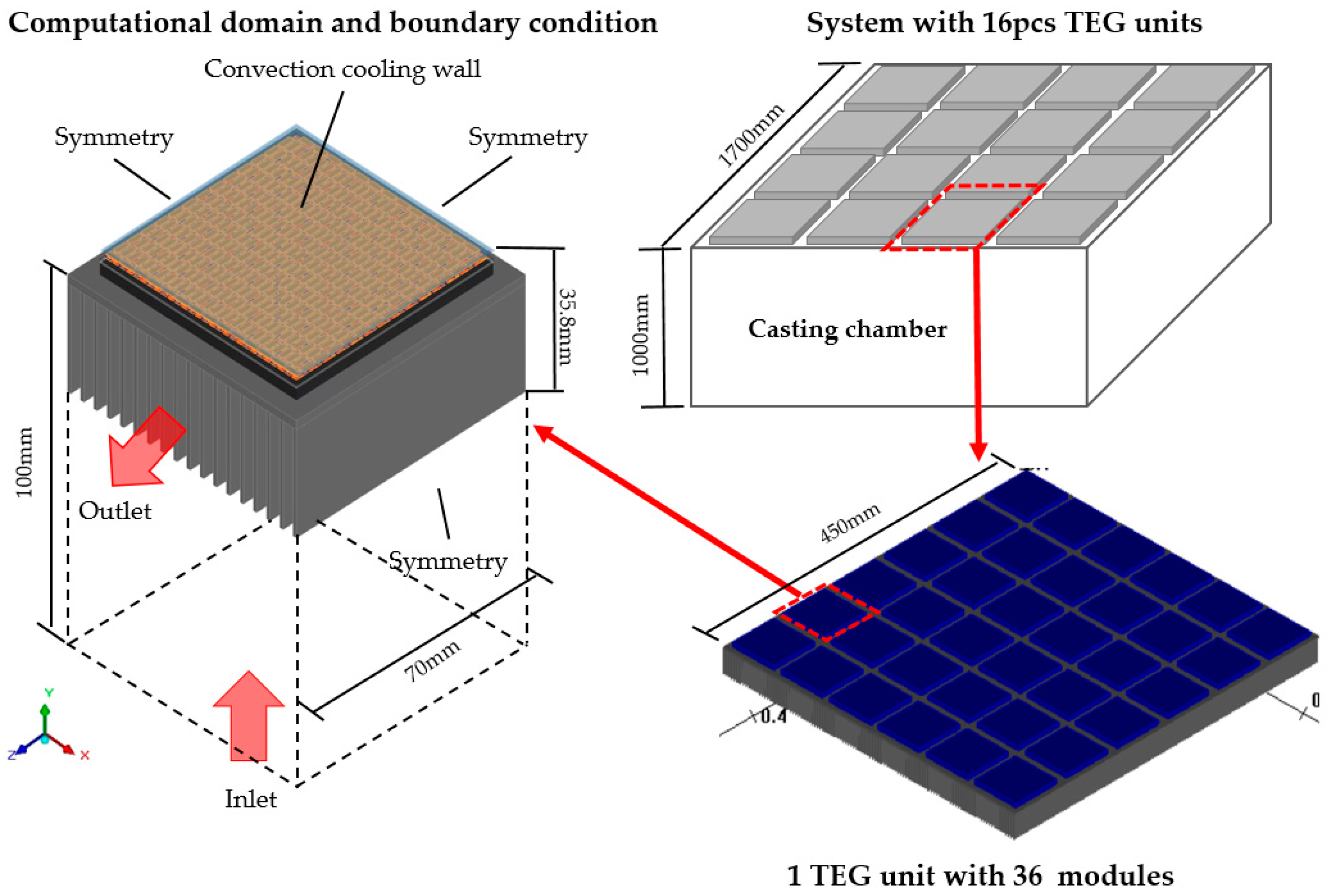
The present industrial tests are aimed at recovering the waste heat in the bronze ingot casting industry in Korea using a TEG system. Figure 1 shows a photograph of a WHR system using heat sink-based TEGs. A total of 16 TEG units are installed on the top of the combustion chamber and connected in parallel. Each unit consists of 36 modules connected in series. A total of 576 TEG modules are used for the WHR from the ingot casting process. A schematic of the waste-heat flow during the casting process is shown in Figure 2. The mold inside the casting chamber must be preheated by fire from the combustion of natural gas for casting a large-scale bronze ingot. The flue gas generated in this preheating process moves upward, and therefore, the waste heat is recovered by installing the TEG assemblies on the top of the chamber. In these industrial tests, a standard PF heat sink was installed on the hot side of the TEG system to improve the heat recovery performance. The TEG modules used in this study were developed and manufactured by LivingCare Co., Ltd. Korea. Each module is composed of hot- and cold-side insulators, with 391 electrodes on each side, and 391 pairs of N-P-type semiconductors, comprising the materials of ceramic, copper, and Bi2Te3, respectively. The detailed parameters of the geometry and thermo-electrical properties of the TEG module components are listed in Table 1. Note that the thermal and electrical properties of the semiconductors are evaluated as functions of the temperature [28].

3. Numerical Model

3.1. Boundary Conditions

A 3D multiphysics numerical model coupling the governing equations of fluid, thermal, and electrical models was established and solved using ANSYS 19.2 software. Owing to the large aspect ratio and size differences between various parts of the system, representing the entire system through one computational model is almost impossible. Therefore, the computational domain was simplified. Figure 3 presents a schematic of the simplified computational domain used in the numerical simulations. It corresponds to a single TEG module-based system. The flue gas inlet boundary was assumed to be 100 mm below the surface of the fin base. The properties of the exhaust gas were assumed to be replaced by those of air [29], and its temperature and velocity were found to vary in the ranges of 545–650 °C and 0.5–7 m/s, respectively. Therefore, in the numerical simulations, the reference temperature for all cases was set at 600 °C, and the inlet velocities were set at 1, 3, 5, and 7 m/s. The outlet boundary condition was applied on the maximum z-surface of the computational domain. The other three vertical planes were set as symmetrical (Figure 2). All solid interfaces were specified as no-slip wall boundary conditions. During the experiments, cold water flowed through a heat exchanger to cool the cold side of the TEG system. Because the cooling performance of the TEG was not considered in the numerical study, a constant heat transfer coefficient was specified on the cold side of the TEG for all test specimens, based on the experimental data. This coefficient was evaluated using the Dittus–Boelter correlation [1].

3.2. Fluid Model

In this study, the flow was considered incompressible because its Mach number is less than 0.1. For this steady incompressible flow, the continuity, momentum, and energy equations in the fluid region are expressed as follows:
v = 0
( v v ) = 1 ρ p + μ 2 v
( ρ v T ) = k c p 2 T
where v, p, ρ, µ, k, T, and cp are the fluid velocity, pressure, density, dynamic viscosity, thermal conductivity of the material, temperature, and specific heat, respectively.
In this study, the Spalart–Allmaras one-equation model was used as the turbulence model. This turbulence model has been demonstrated to yield good results for boundary layers subjected to adverse pressure gradients. Wong et al. [30] developed a numerical model for an air-impinged PF heat sink using the Spalart–Allmaras turbulence model, and the model was in good agreement with both the experimental result [31] and the exact solution [32]. The transport equation for kinematic turbulent viscosity in the Spalart–Allmaras model is expressed as follows:
x i ( ρ v ˜ u i ) = G ν + 1 σ v ˜ { x j [ ( μ + ρ v ˜ ) v ˜ x j ] + C b 2 ρ ( v ˜ x j ) 2 } Y ν

3.3. Thermoelectric Model

For the analysis of the thermoelectric system, the 3D governing equations including the thermal, electrical, and thermoelectric effects at a steady state are as follows [13]:
q = q ˙
J = 0
For the thermoelectric material, when the temperature gradient, ∇T, is provided, the heat flux and the electrical field are expressed as
q = α T J k T
E = α T + r J
where α, k, r, and J denote the Seebeck coefficient, thermal conductivity, resistivity, and current density, respectively. In Equation (6), the heat generation term, which includes the electric power spent on Joule heating, is obtained by
q ˙ = J E

3.4. Numerical Methods

ANSYS Icepak 19.2 was used to solve a pressure-based Navier–Stokes equation for the fluid flow. A second-order discretization scheme was used for all convection terms in the transport equation. The convergence criteria for continuity, turbulence, and energy are set as 1 × 10⁻⁴, 1 × 10⁻⁴, 1 × 10⁻⁷, respectively. A grid independence test was conducted for the same fin parameters (PF heat sink, Hf = 28.6 mm, Nf = 18) and the same inlet boundary conditions (Vin = 3 m/s, Tin = 600 °C). The temperature difference between the hot- and cold sides of the TEG was compared for test cases with different element numbers. The test results indicate that the optimum number of elements is 14 million, which was used for all test specimens considered in the present numerical analysis. The primary temperature distributions of both the hot and cold sides of the TEG module obtained from the CFD simulations were exported to ANSYS Mechanical as the boundary conditions of the thermal–electric coupled simulation.
The power output across the module can be obtained from
P T E G = ( U 0 R T E G I ) I = U 0 2 R L ( R L + R T E G ) 2
where RL and RTE are the external load and internal resistance of the TEG, respectively. The maximum power output (Pmax) is generated when the external load resistance is equal to the TEG internal resistance. Therefore, the maximum power point of the TEG under a steady temperature difference occurs at half of the open-circuit voltage [33], and can be calculated using
P max = = U 2 R L = U 0 2 4 R T E G
A pressure drop across the fin increases the pumping power required to flow hot gas. Therefore, the maximum net power output and the corresponding net efficiency of the TEG module can be evaluated using
P n e t , max = P max Δ P V ˙
η n e t , max = P max Q h
In this study, three types of heat sinks with different fin structures—PF, CPF, and RPF—were used in the numerical simulations (Figure 4). The dimensions of the three fin types are provided in Table 2. To compare the effect of the fin type, the heat sinks were designed at three heights, and each type of heat sink had almost the same fin area for each height. Therefore, 36 cases (three fin types × three fin heights × four inlet velocities) were examined in the numerical analysis. The fin base area was 0.07 × 0.07 m2, which was slightly larger than the TEG module area. All three types of heat sinks were formed from aluminum with a thermal conductivity of 167 W/mK, data provided by the manufacturer.

4. Validation of Computational Model

For the multiphysics simulations, the computational model was validated for the characteristics of the fluid flow, heat transfer, and electrical power generation. In this study, for the fluid model, the pressure drop of the PF heat sink was important for the evaluation of the TEG efficiency. However, measuring the pressure value in the system was difficult owing to industrial constraints. Therefore, the computational model used in this study was validated by comparing it with both experimental [31] and numerical simulation [34] results from previous studies. The same geometry of the PF heat sink, boundary conditions, and flow direction (impingement flow) used in the respective previous studies [31,34] were employed in the present numerical model. The temperature distribution of the heat sink, pressure drop across the fin, and thermal resistance of the heat sink were obtained. A comparison of the results is shown in Figure 5 and Figure 6.
The maximum variations in the pressure drop and thermal resistance, compared to the experimental study [31] results, were 9.2% and 6.1%, respectively. The corresponding maximum variations relative to the numerical study [34] values were 17.5% and 14.2%. The variations in the results obtained using the present model relative to those of the previous numerical study [34] were slightly high. These deviations of both properties may be due to the differences in the mesh systems, solver settings, or turbulent models. However, the results obtained using the present computational model were in good agreement with the results of the previous experimental study [31]. Therefore, the present computational model was validated and used in the subsequent numerical investigations.
The heat transfer characteristics of the solid components of the TEG module were validated by comparing the correlations between the hot- and cold-side temperatures of the module. During the industrial tests, the temperatures on the hot and cold sides of the TEG were measured for one module. Note that the heat transfer characteristics across the internal components of the TEG module were independent of the external boundary conditions. In the same system, the error of the cold-side temperature from the measurement and simulation data was verified by keeping the temperature on the hot side constant. Therefore, in the numerical simulations, the temperatures of the hot and cold sides of the TEG in 36 cases were determined and compared with the measurement data (Figure 7). The maximum variation between the measurement data and the simulation results was below 5%.
Finally, the electrical power output of the TEG module was validated using measured data. Figure 8 compares the voltage and TEG output power obtained from measurements and simulations by varying the external load resistance when the inlet velocity and the temperature of the flue gas were 1 m/s and 550 °C, respectively. The maximum error in the power output was 10.13% when the external load was 42 Ω. The variation in the power output may be due to the unstable conditions of the flue gas during the industrial tests.
Here, it should be emphasized that in the experimental test, only the PF heat sink was applied to the heat recovery of the waste heat, due to some industrial constraints. Therefore, only the numerical results for the PF based TEG module were verified using measured data. However, good agreement occurred between the measured data and the numerical results, and the computational model was deemed to represent the fluid, thermal, and electrical characteristics well.

5. Results and Discussion

Numerical simulations were conducted to evaluate the effects of the fin structures on the TEG performance at different fin heights (20.6, 28.6, and 36.6 mm) and inlet flue gas velocities (1, 3, 5, and 7 m/s). The inlet temperature of the flue gas (600 °C) was fixed in the multiphysics computational model. The characteristics of the fluid, thermal, and electrical properties were analyzed.

5.1. Fluid Analysis

It has been argued that increasing the flue gas velocity requires more auxiliary pumping power (Ppump) in a flow regime. Fin structures have a major effect on the pressure drop. Figure 9 and Figure 10 show the pressure drop and the corresponding pumping power as functions of the inlet flue gas velocity at a temperature of 600 °C for each of the fin types tested. The RPF heat sink showed similar characteristics to the PF heat sink; however, the pressure drop and pumping power were slightly higher for the former. Unlike for air flow along the fin length, for an impingement flow, increasing the fin height decreased the pressure drop and the pumping power, when the flue gas flow was normal to the fin base for the PF and RPF heat sinks. Similar results were reported by Park et al. [35]. However, for the CPF heat sink, this feature manifested only when the flue gas velocity was lower than 5 m/s. Notably, the CPF heat sink presented a lower pressure drop than the other two types, and may have had a large impact on the net power generation and net efficiency of the TEG system.

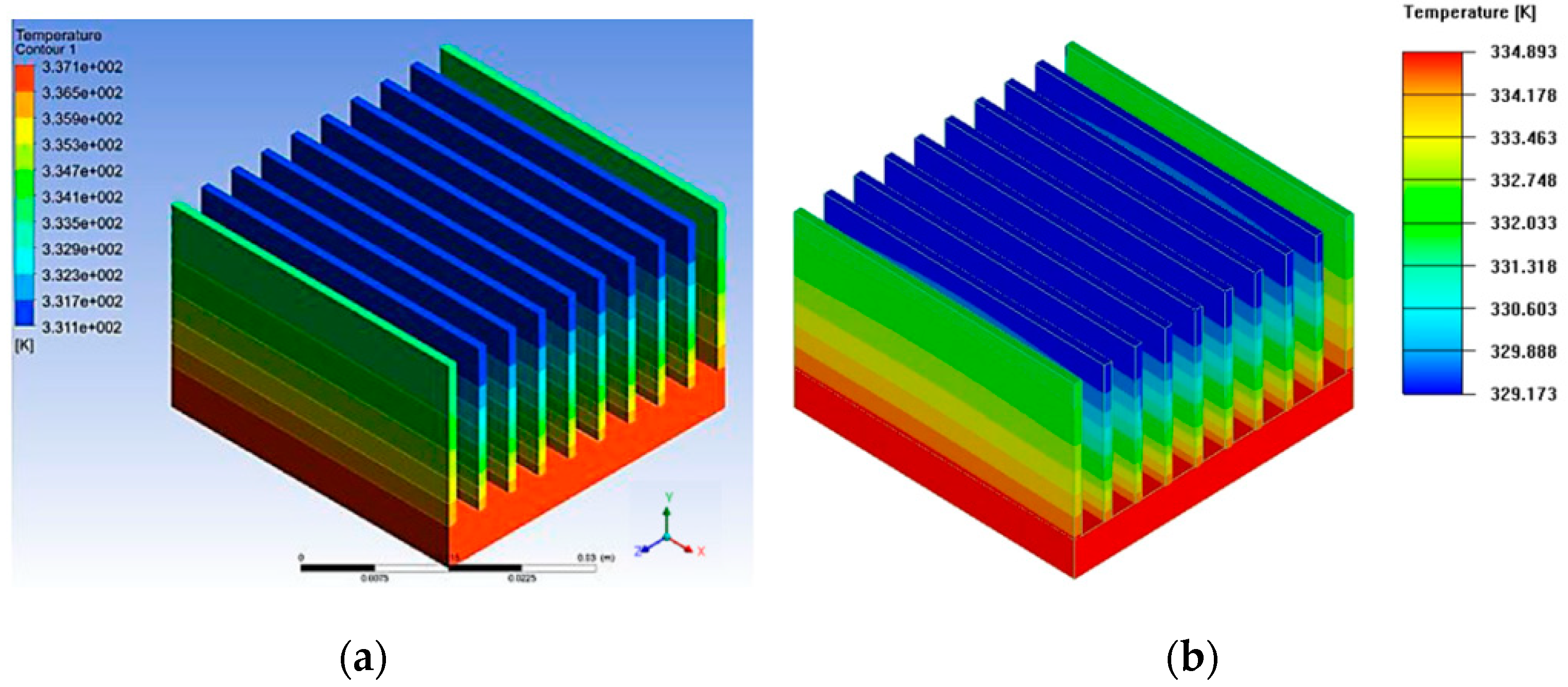
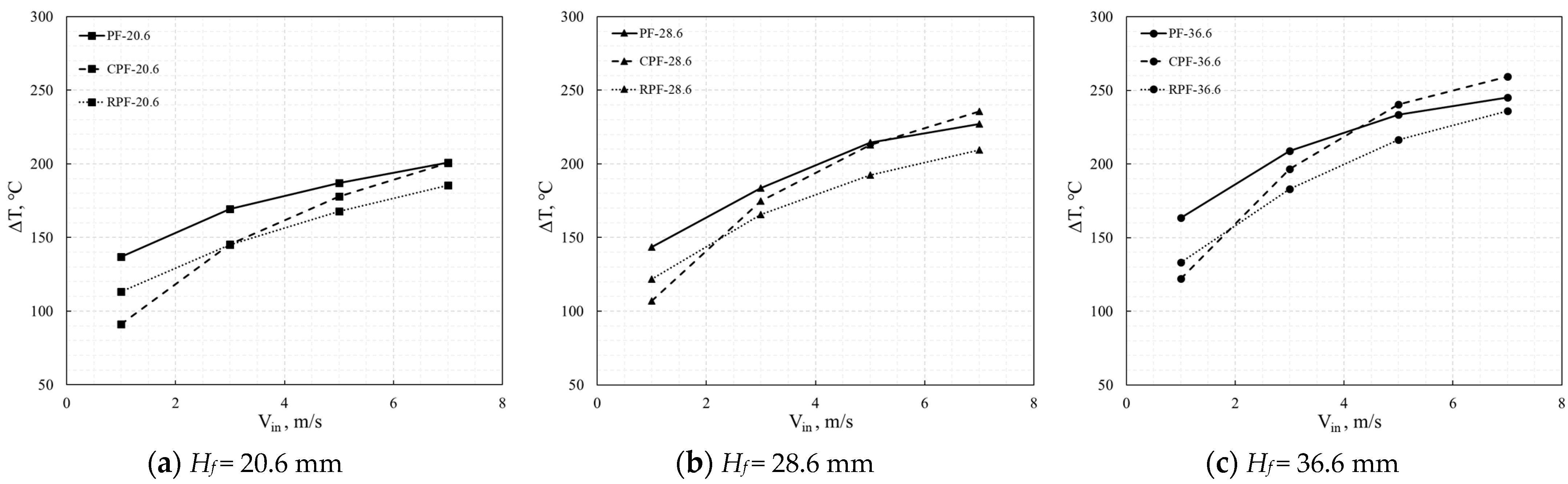
5.2. Thermal Analysis

Figure 11 depicts the temperature distributions across various layers of the TEG module when the inlet flue gas temperature and velocity were 600 °C and 1 m/s, respectively. Owing to the low thermal conductivity of N–P type semiconductors, heat transfer occurs across the TEG layers and a large temperature drop is observed between the hot and cold sides of the TEG module. On the hot side of the TEG, the temperature in the middle part is lower than that in the edge part. This can be mainly attributed to the area of the module being smaller than that of the heat sink, resulting in a higher temperature at the edge of the heat sink than that in the middle part.
The temperature distributions of the heat sinks with different fin structures and inlet velocities of the flue gas are compared in Figure 12. For all inlet velocities, the RPF heat sinks presented the worst performance in terms of the heat transfer. When the inlet flue gas velocity was 3 m/s, the fin base temperature of the PF heat sink was higher than those of the CPF and RPF heat sinks. However, when the inlet flue gas velocity was higher than 5 m/s, the highest fin base temperature was observed in the CPF heat sink. The temperature difference between the hot and cold sides of the TEG module were highly dependent on the fin base temperature. The same correlations were also found from the temperature difference between the hot and cold sides of the TEG module (Figure 13).

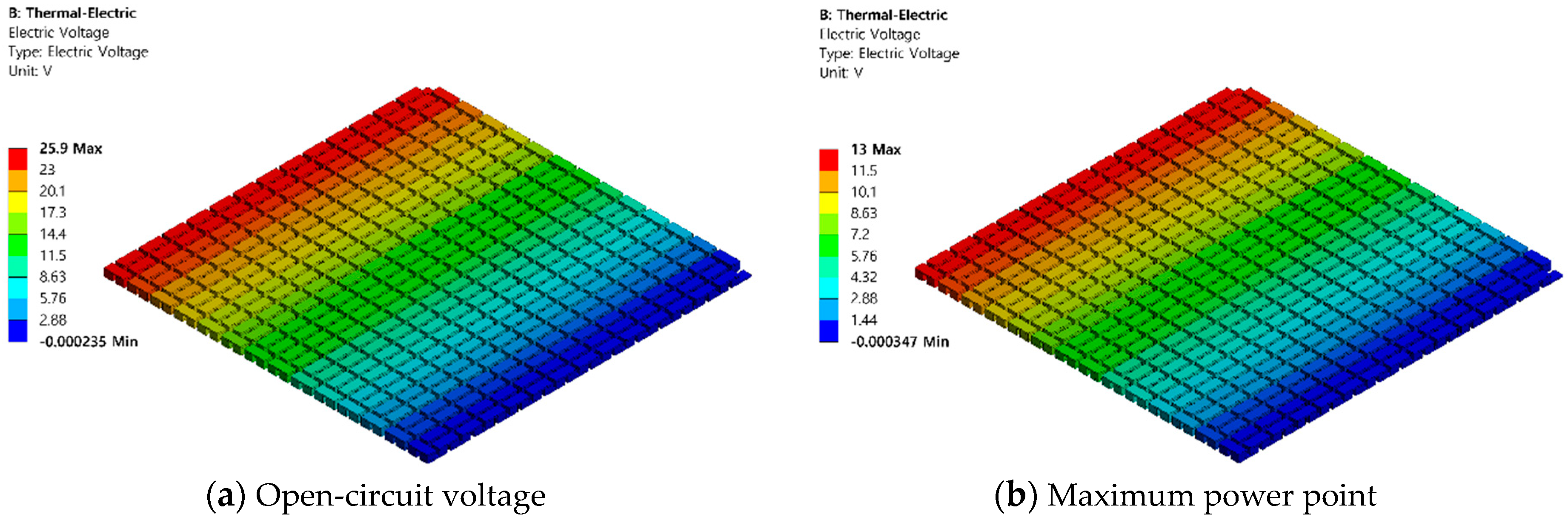
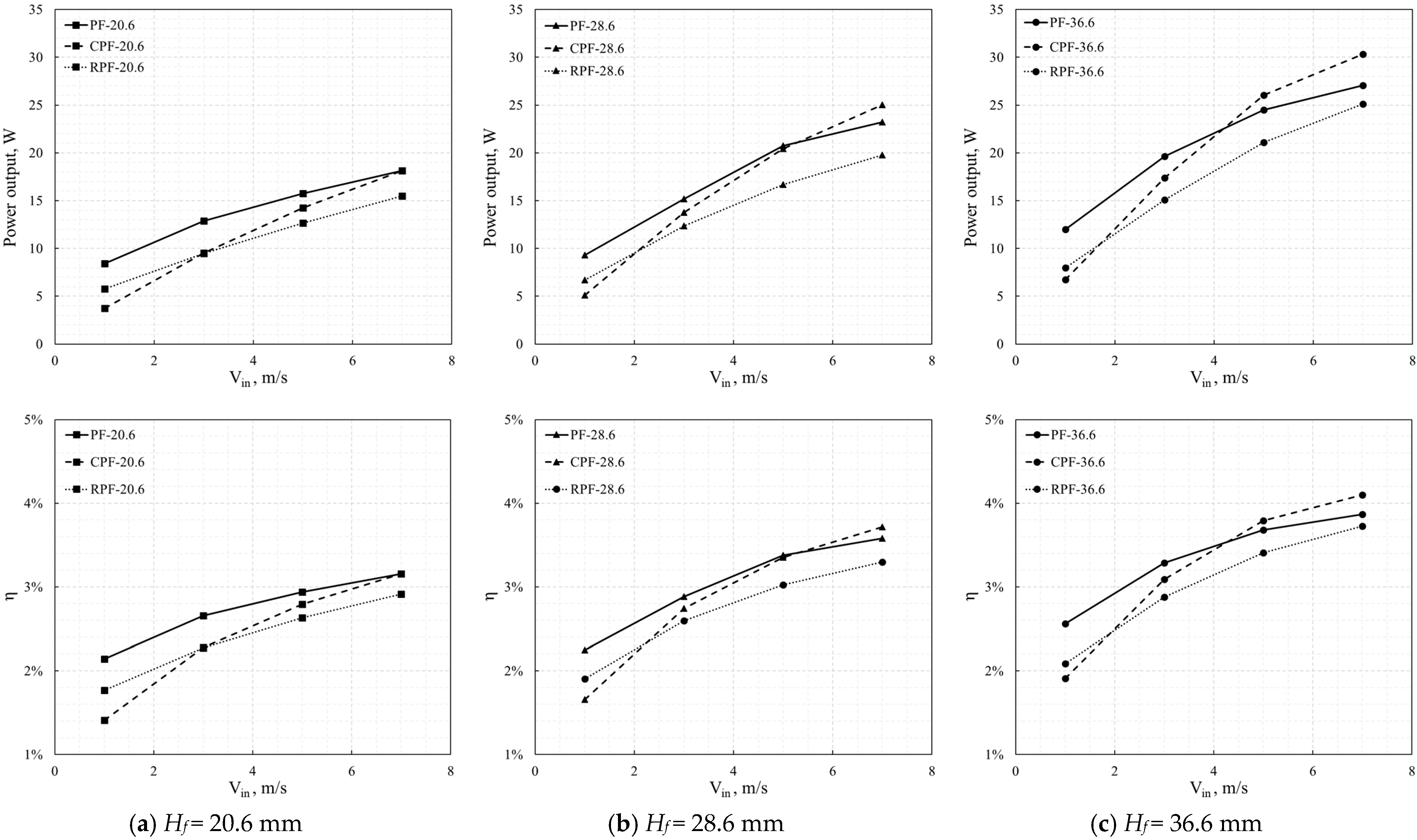
5.3. Electrical Analysis

Following the CFD simulations, the temperature profiles obtained for the hot and cold sides of the TEG module were exported to ANSYS Mechanical 19.2 for the electrical simulations. The electrical potential across the semiconductors in the TEG module was evaluated. Figure 14 depicts the electrical potential of the TEG module under the same inlet conditions (Vin = 3 m/s and Tin = 600 °C). The results present the distributions of the electrical potential at the open-circuit voltage and the maximum power point (MPP), respectively. As previously mentioned, the electrical potential at the maximum power point of the TEG under a steady temperature difference lies at half of the open-circuit voltage. Moreover, the maximum power output can be evaluated using Equation (12). Therefore, to save computational resources, for all 36 simulations, only the electric voltages at the open-circuit were evaluated.
The power outputs and efficiencies of the TEG module obtained with different fin structures and the variations in the inlet flue gas velocity were evaluated and are compared in Figure 15. For all three types of heat sinks, an increased fin height led to a larger heat transfer area, which increased the maximum power output (Pmax) and the maximum efficiency (ηmax). Pmax and ηmax also increased with an increase in the inlet flue gas velocity. However, for the TEG with the CPF heat sink, the growth rates of Pmax and ηmax following the increase in the inlet flue gas velocity were higher than those of the other types. After the inlet flue gas velocities exceeded 7 m/s, 5 m/s, and 4.5 m/s, the TEG module with the CPF heat sink presented better performance than the others for fin heights of 20.6 mm, 28.6 mm, and 36.6 mm, respectively. The highest values of Pmax and ηmax were 30.3 W and 4.1%, respectively, when the fin height and the inlet flue gas velocity were 36.6 mm and 7 m/s, respectively.
To analyze the overall TEG performance, the auxiliary pumping power (Ppump) of the system was considered. As can be seen in Figure 16, the PF-based system showed better performance than the other systems when the inlet flue gas velocity was lower than 4 m/s. As mentioned earlier, the systems with PF and RPF heat sinks presented higher pressures than that with a CPF heat sink. Therefore, a higher pumping power was required in the cases of PF and RPF heat sinks. The maximum net power output (Pnet,max) and efficiency (ηnet,max) of the TEG system decreased when Vin exceeded 5 m/s for the PF and RPF heat sinks. In particular, for a fin height of 20.6 mm, the maximum net efficiency decreased after the Vin exceeded 3 m/s. However, this tendency is nonremarkable in the CPF heat sink system because of its lower pressure drop. The highest values of the maximum net power output and the efficiency were 25.27 W and 3.49 in the CPF heat sink-based system, when the inlet flue gas velocities were 7 m/s and 5 m/s, respectively. Based on the above discussion and analysis, it was concluded that the performance of the RPF heat sink was the worst, and it should not be used in any working condition. When the inlet velocity of the exhaust gas was less than 4–5 m/s, the PF heat sink was helpful in enhancing the system power output and efficiency, and when the inlet velocity was higher than 5 m/s, the CPF was the best choice.

6. Conclusions

In this study, heat sinks were used on the hot side of a TEG to recover the waste heat from the flue gas in a brass ingot casting system. The flow direction was found to be normal to the heat sink base. Three types of heat sinks with different fin structures (PF, CPF, and RPF) were investigated. To evaluate the effect of the fin structure on the TEG performance, a 3D multiphysics numerical model was developed and validated by referenced studies, and data were measured via industrial tests. Numerical investigations were conducted in terms of the fluid, thermal, and electrical characteristics of the system with different fin types, fin heights, and various working conditions. The following conclusions were drawn from the numerical investigations:
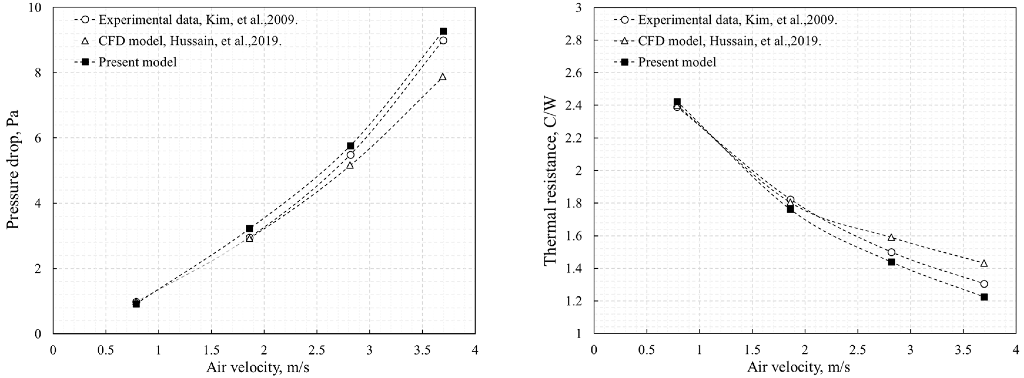
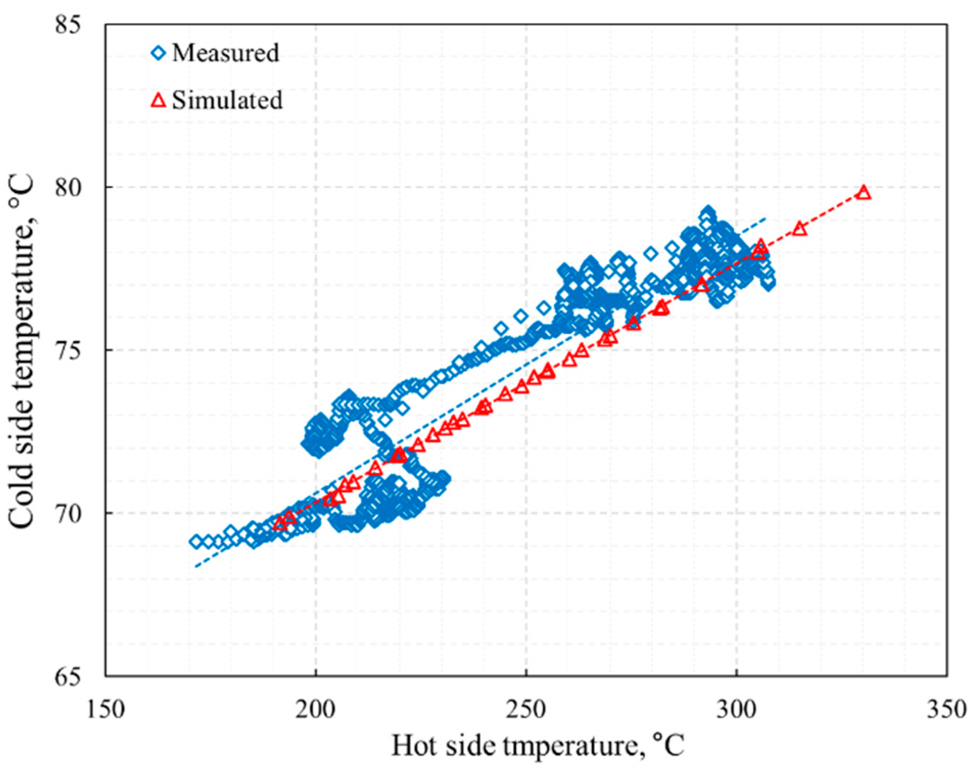
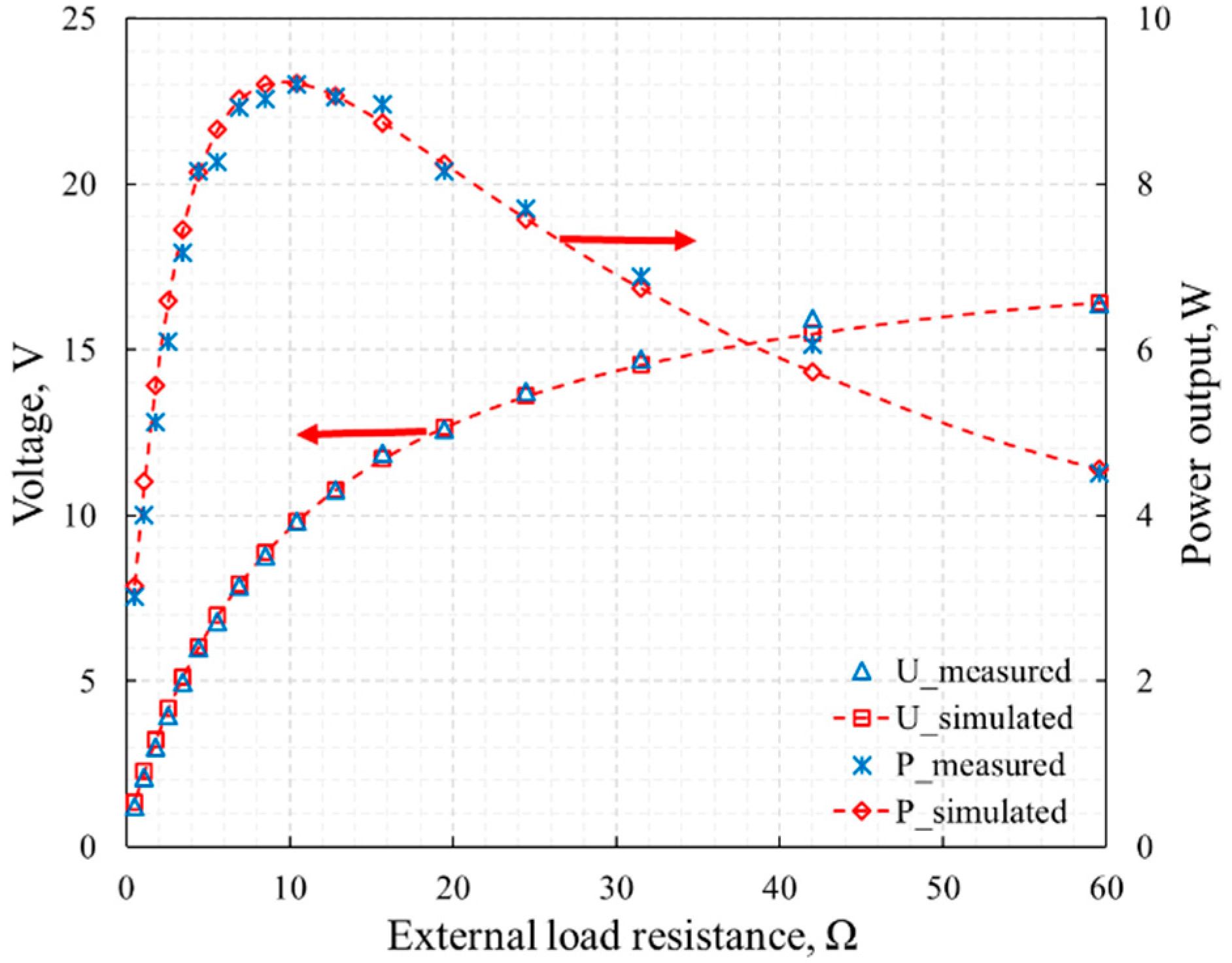
The 3D multiphysics computational model was developed by simplifying the entire system into one module-based system. The results from the numerical simulations were in good agreement with the results from the reference studies and the measured data.
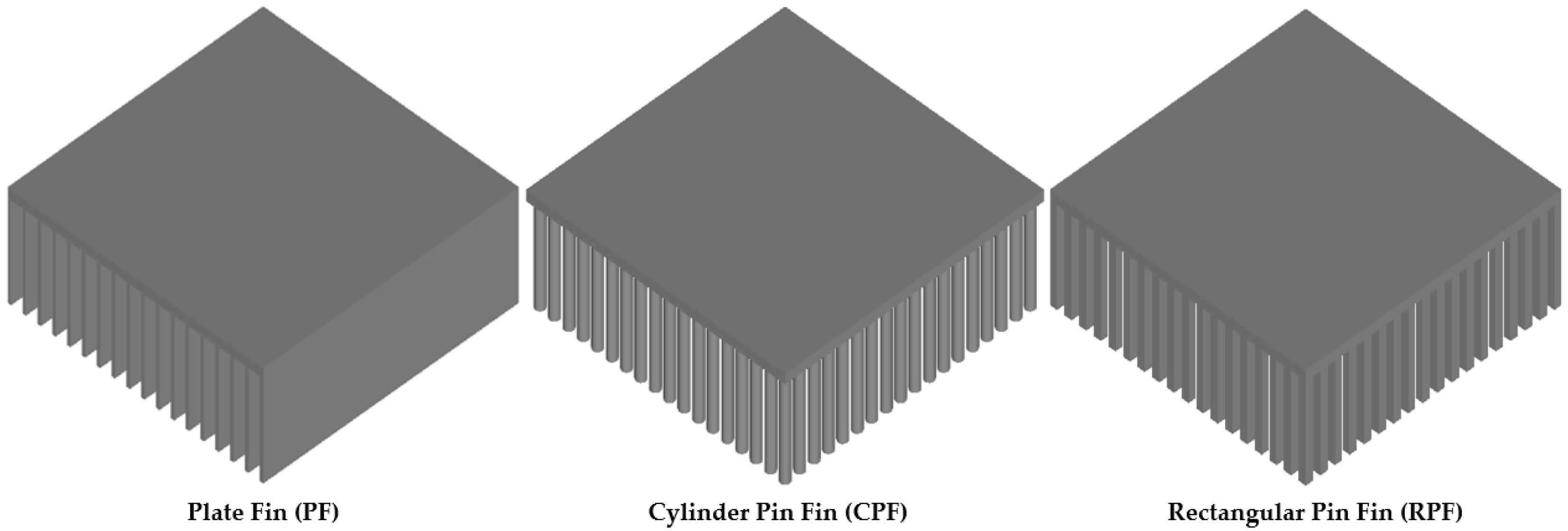
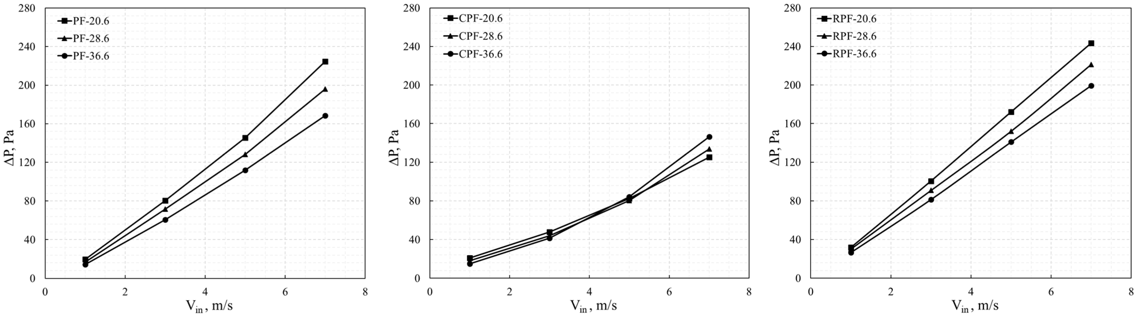
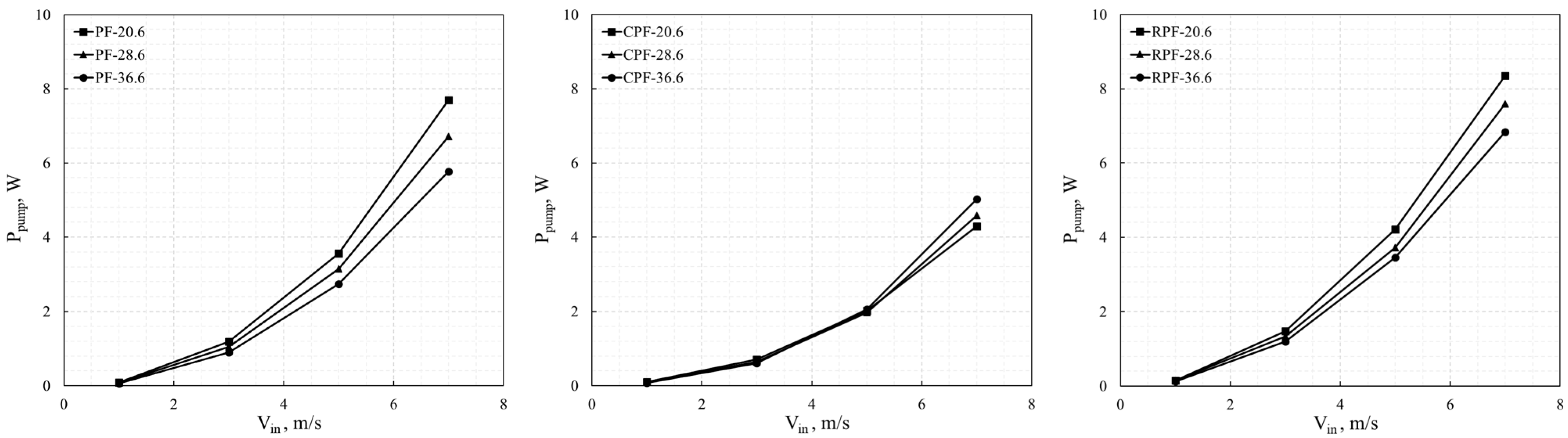
In most instances, the CPF heat sink presented a much lower pressure drop and pumping power than the PF and RPF heat sinks.
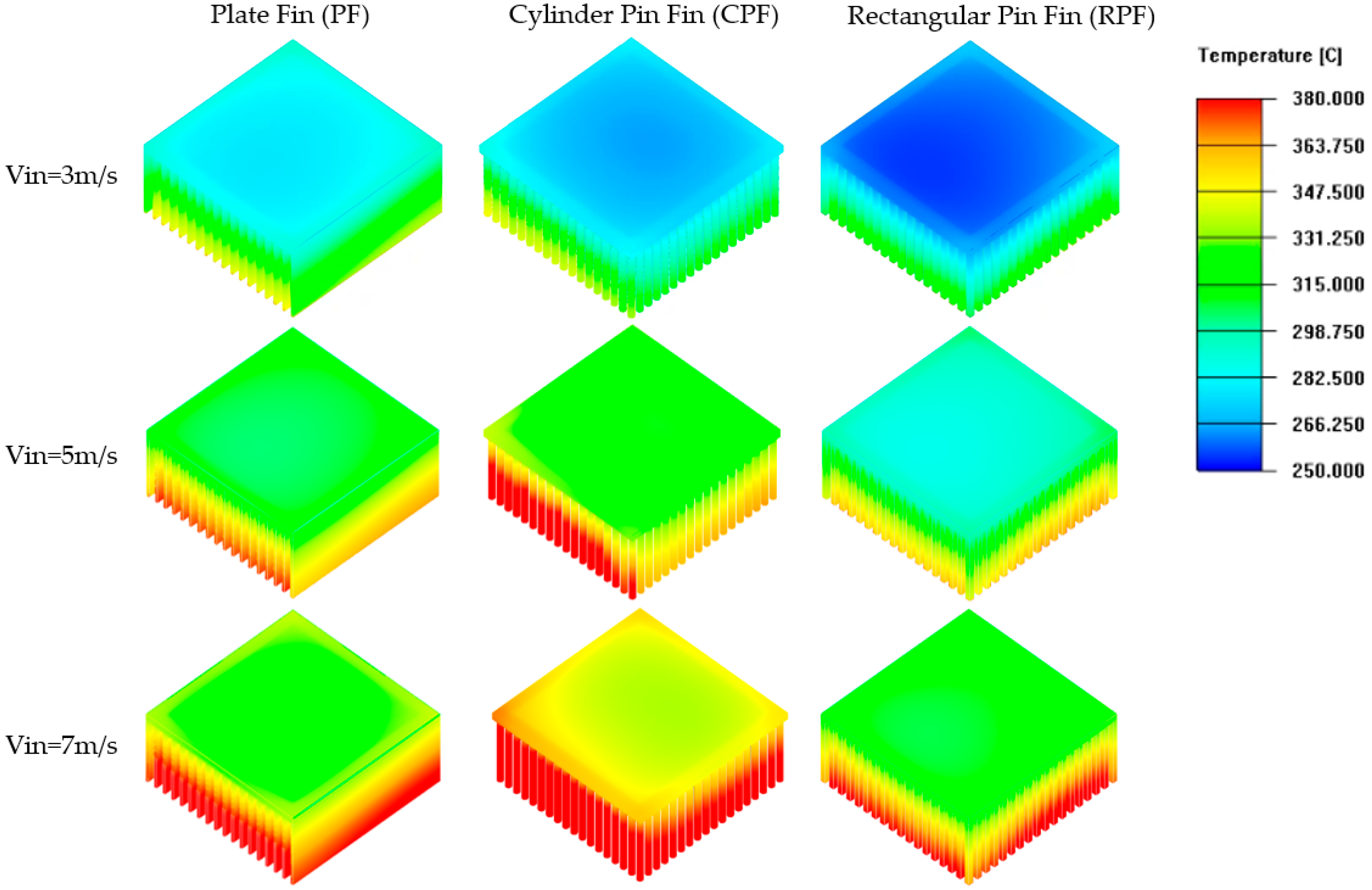
When the inlet velocity of the flue gas was lower, the PF heat sink showed a better heat transfer performance, whereas the CPF heat sink presented the best heat transfer when the flue gas was at a higher inlet velocity. This correlation also applied to the maximum power output and TEG efficiency.
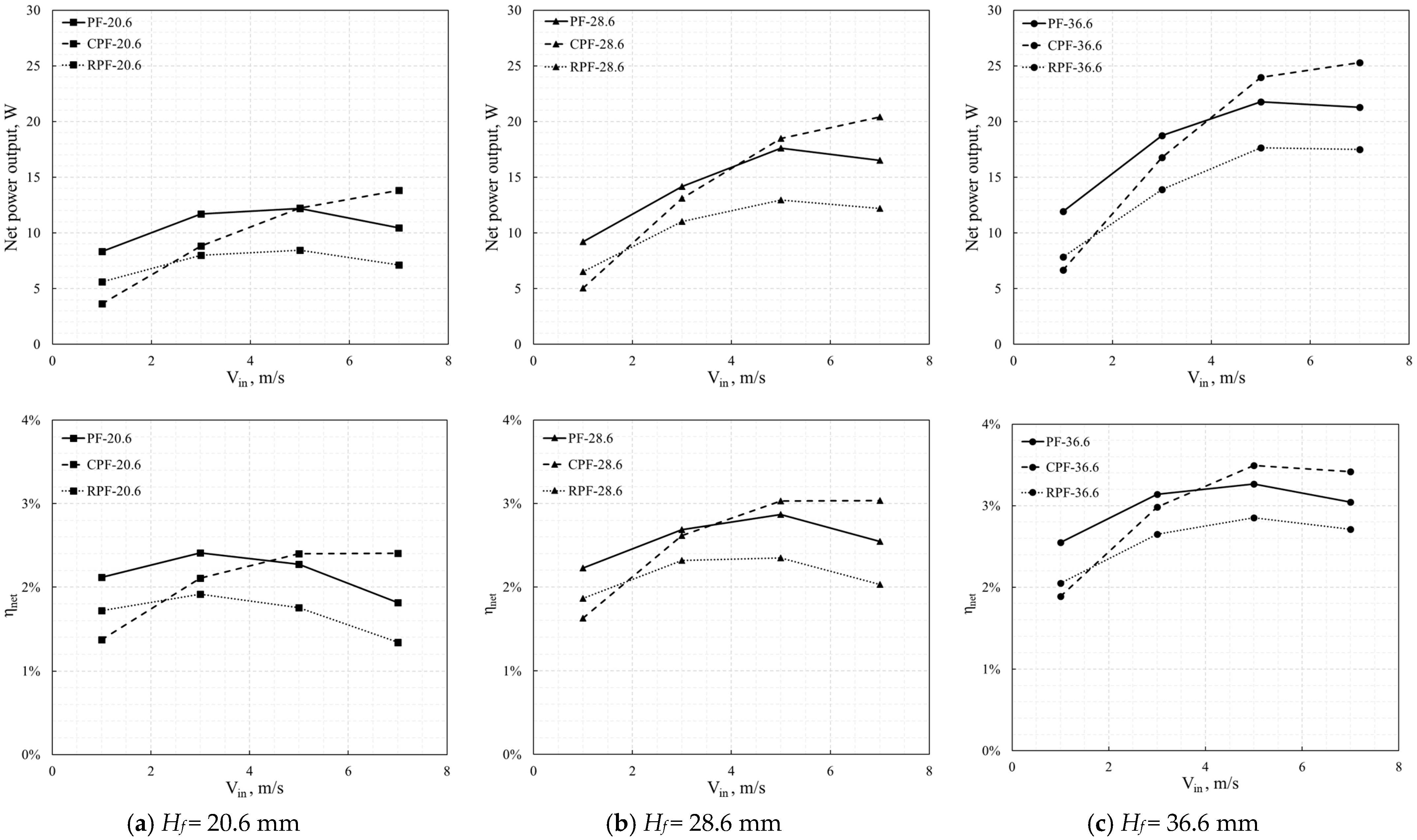
The system pressure drop led to auxiliary pumping power. The maximum net power output and efficiency of the TEG system tended to decrease after the inlet velocity of the flue gas exceeded 5 m/s for the PF and RPF heat sinks. In comparison, this trend was unremarkable for the CPF heat sink.
When the inlet velocity of the flue gas was lower than 4–5 m/s, the PF heat sink helped to increase the system power output and efficiency. In contrast, when the inlet velocity of the flue gas was higher than 5 m/s, CPF heat sink was the best option.
For the existing TEG-based heat recovery systems, the results from the numerical analysis provide an important reference for the selection of heat sinks, thereby improving their performance.
However, more experimental tests must be conducted without industrial constraints. Numerical simulations for more types of heat sinks under different working conditions, such as varying inlet flue gas temperatures, also need to be conducted in future studies. Additionally, an optimization analysis could be developed based on the results from further numerical studies.

Author Contributions

J.L. performed the system modeling and numerical analyses and drafted the manuscript. S.C.K. collected the measured data, organized the overall evaluation, and reviewed the manuscript. K.-Y.S. discussed the results of this study. All authors have read and agreed to the published version of the manuscript.

Funding

This work was conducted as part of the Energy Technology Development project sponsored by the Ministry of Trade, Industry, and Energy (No. 20172010000760), and supported by the 2022 Yeungnam University Research Grant.

Institutional Review Board Statement

Not applicable.

Informed Consent Statement

Not applicable.

Data Availability Statement

Not applicable.

Acknowledgments

The support from the LIVINGCARE company and Seowon company is greatly appreciated.

Conflicts of Interest

The authors declare no conflict of interest.

Nomenclature

AArea (mm2)Greek symbols
aGas absorption coefficient (m−1)αSeebeck coefficient, (μV/K)
cpSpecific heat (W/kg⸱k)βThomson coefficient, (μV/K)
GvProduction of turbulent viscosityηTEG conversion efficiency, (%)
HFin height (mm)vFluid velocity, (m/s)
IElectrical current (A)ρDensity, (kg/m3)
JCurrent density (A/m2)µDynamic viscosity, (kg/m s)
kThermal conductivity (W/mk)
NFin numberSubscripts
PmaxMaximum power output, (W)bFin base
Pnet,maxNet maximum power output, (W)cCold side of the TEG module
pPressure, (Pa)eiElectrical insulator
QhHeat flux to hot side of the TEG, (W)ecElectrodes
R, rElectrical resistivity of the electrodes, (Ωm)fFin
tThickness (mm)hsHeat sink
TTemperature, (°C)LExternal load
ThHot side temperature of the TEG module (°C)mppMaximum power point
TcCold side temperature of the TEG module (°C)nn-type of semiconductor
U0Open voltage of the TEG module (V)ocOpen circuit
VFlue gas velocity (m/s)pp-type of semiconductor
YvDestruction of the turbulent viscosityTEGThermoelectric generator

References

  1. Khalil, H.; Hassan, H. Enhancement of waste heat recovery from vertical chimney via thermoelectric generators by heat spreader. Process. Saf. Environ. Prot. 2020, 140, 314–329. [Google Scholar] [CrossRef]
  2. Kuroki, T.; Murai, R.; Makion, K.; Nagano, K.; Kajihara, T.; Kaibe, H.; Hachuma, H.; Matsuno, H. Research and Development for Thermoelectric Generation Technology Using Waste Heat from Steelmaking Process. J. Electron. Mater. 2015, 44–46, 2151–2156. [Google Scholar] [CrossRef]
  3. Formann, C.; Muritala, I.K.; Pardemann, R.; Meyer, B. Estimating the global waste heat potential. Renew. Sustain. Energy Rev. 2016, 57, 1568–1579. [Google Scholar] [CrossRef]
  4. Jouhara, H.; Khordehgah, N.; Almahmoud, S.; Delpech, B.; Chauhan, A.; Tassou, S.A. Waste heat recovery technologies and applications. Therm. Sci. Eng. Prog. 2018, 6, 268–289. [Google Scholar] [CrossRef]
  5. Lv, S.; He, W.; Jiang, Q.; Hu, Z.; Liu., X.; Chen, H.; Liu, M. Study of different heat exchange technologies influence on the performance of thermoelectric generators. Energy Convers. Manag. 2018, 156, 167–177. [Google Scholar] [CrossRef]
  6. Zaher, M.H.; Abdelsalam, M.Y.; Cotton, J.S. Study of the effects of axial conduction on the performance of thermoelectric generators integrated in a heat exchanger for waste heat recovery applications. Appl. Energy 2020, 261, 114434. [Google Scholar] [CrossRef]
  7. Luo, D.; Wang, R.; Yu, W. Comparison and parametric study of two theoretical modeling approaches based on an air-to-water thermoelectric generator system. J. Power Sources 2019, 439, 227069. [Google Scholar] [CrossRef]
  8. Luo, D.; Wang, R.; Yu, W.; Zhou, W. A novel optimization method for thermoelectric module used in waste heat recovery. Energy Convers. Manag. 2020, 209, 112645. [Google Scholar] [CrossRef]
  9. Pacheco, N.; Brito, F.P.; Vieira, R.; Martins, J.; Barbosa, H.; Goncalves, L.M. Compact automotive thermoelectric generator with embedded heat pipes for thermal control. Energy 2020, 197, 117154. [Google Scholar] [CrossRef]
  10. Bai, W.; Yuan, X.; Liu, X. Numerical investigation on the performances of automotive thermoelectric generator employing metal foam. Appl. Therm. Eng. 2017, 124, 178–184. [Google Scholar] [CrossRef]
  11. Liu, X.; Deng, Y.D.; Li, Z.; Su, C.Q. Performance analysis of a waste heat recovery thermoelectric generation system for automotive application. Energy Convers. Manag. 2015, 90, 121–127. [Google Scholar] [CrossRef]
  12. Zhao, Y.; Wang, S.; Ge, M.; Liang, Z.; Liang, Y.; Li, Y. Performance investigation of an intermediate fluid thermoelectric generator for automobile exhaust waste heat recovery. Appl. Energy 2019, 239, 425–433. [Google Scholar] [CrossRef]
  13. Jang, J.Y.; Tsai, Y.C.; Wu, C.W. A study of 3-D numerical simulation and comparison with experimental results on turbulent flow of venting flue gas using thermoelectric generator modules and plate fin heat sink. Energy 2013, 53, 270–281. [Google Scholar] [CrossRef]
  14. Børset, M.T.; Wilhelmsen, Ø.; Kjelstrup, S.; Burheim, O.S. Exploring the potential for waste heat recovery during metal casting with thermoelectric generators: On-site experiments and mathematical modeling. Energy 2017, 118, 865–875. [Google Scholar] [CrossRef]
  15. Yadav, S.; Liu, J.; Kong, M.S.; Yoon, Y.G.; Kim, S.C. Heat Transfer Characteristics of Thermoelectric Generator System for Waste Heat Recovery from a Billet Casting Process: Experimental and Numerical Analysis. Energies 2021, 14, 601. [Google Scholar] [CrossRef]
  16. Tian, Z.; Lee, S.Y.; Chen, G. A Comprehensive Review of Heat Transfer in Thermoelectric Materials and Devices. Annu. Rev. Heat Transf. 2014, 17, 425–483. [Google Scholar] [CrossRef]
  17. Bittner, M.; Kanas, N.; Hinterding, R.; Steinbach, F.; Räthel, J.; Schrade, M.; Wiik, K.; Einarsrud, M.A.; Feldhoff, A. A comprehensive study on improved power materials for high-temperature thermoelectric generators. J. Power Sources 2019, 410–411, 143–151. [Google Scholar] [CrossRef]
  18. Ouyang, Z.; Li, D. Modelling of segmented high-performance thermoelectric generators with effects of thermal radiation, electrical and thermal contacted resistance. Sci. Rep. 2016, 6, 24123. [Google Scholar] [CrossRef]
  19. Dhass, A.D.; Krishna, R.; Sreenivasan, M. Numerical analysis of a variety of thermoelectric generator materials. Mater. Today Proc. 2020, 33–41, 29–34. [Google Scholar] [CrossRef]
  20. Luo, D.; Wang., R.; Yu, W.; Zhou, W. A numerical study on the performance of a converging thermoelectric generator system used for waste heat recovery. Appl. Energy 2020, 270, 115181. [Google Scholar] [CrossRef]
  21. Yan, S.R.; Moria, H.; Asaadi, S.; Dizaji, H.S.; Khalilarya, S.; Jermsittiparsert, K. Performance and profit analysis of thermoelectric power generators mounted on channels with different cross-sectional shapes. Appl. Therm. Eng. 2020, 176, 115455. [Google Scholar] [CrossRef]
  22. Borcuch, M.; Musiał, M.; Gumuła, S.; Sztekler, K.; Wojciechowski, K. Analysis of the fins geometry of a hot-side heat exchanger on the performance parameters of a thermoelectric generation system. Appl. Therm. Eng. 2017, 127, 1355–1363. [Google Scholar] [CrossRef]
  23. Elghool, A.; Basrawi, F.; Ibrahim, T.K.; Habib, K.; Ibrahim, H.; Idris, D.M.N.D. A review on heat sink for thermo-electric power generation-Classifications and parameters affecting performance. Energy Convers. Manag. 2017, 134, 260–277. [Google Scholar] [CrossRef]
  24. Wang, C.C.; Hung, C.I.; Chen, W.H. Design of heat sink for improving the performance of thermoelectric generator using two-stage optimization. Energy 2012, 39, 236–245. [Google Scholar] [CrossRef]
  25. Rezania, A.; Rosendahl, L.A. A comparison of micro-structured flat-plate and cross-cut heat sinks for thermoelectric generation application. Energy Convers. Manag. 2015, 101, 730–737. [Google Scholar] [CrossRef]
  26. Nayak, R.K.; Ray, S.; Sahoo, S.S.; Satapathy, P.K. Effect of angle of attack and wind direction on limiting input heat flux for solar assisted thermoelectric power generator with plate fin heat sink. Solar Energy 2019, 186, 175–190. [Google Scholar] [CrossRef]
  27. Zheng, L.J.; Kang, H.W. 27-A passive evaporative cooling heat sink method for enhancing low-grade waste heat recovery capacity of thermoelectric generators. Energy Convers. Manag. 2022, 251, 114931. [Google Scholar] [CrossRef]
  28. Demir, M.E.; Dincer, I. Development and heat transfer analysis of a new heat recovery system with thermoelectric generator. Int. J. Heat Mass Transf. 2017, 108, 2002–2010. [Google Scholar] [CrossRef]
  29. Nithyanandam, K.; Mahajan, R.L. Evaluation of metal foam based thermoelectric generators for automobile waste heat recovery. Int. J. Heat Mass Transf. 2018, 122, 877–883. [Google Scholar] [CrossRef]
  30. Wong, K.C.; Indran, S. Impingement heat transfer of a plate fin heat sink with fillet profile. Int. J. Heat Mass Transf. 2013, 65, 1–9. [Google Scholar] [CrossRef]
  31. Kim, D.K.; Kim, S.J.; Bae, J.K. Comparison of thermal performances of plate-fin and pin-fin heat sinks subject to an impinging flow. Int. J. Heat Mass Transf. 2009, 52, 3510–3517. [Google Scholar] [CrossRef]
  32. Kim, D.K.; Kim, S.J. Averaging approach for microchannel heat sinks subject to the uniform wall temperature condition. Int. J. Heat Mass Transf. 2006, 49, 695–706. [Google Scholar] [CrossRef]
  33. Montecucco, A.; Siviter, J.; Knox, A.R. Constant heat characterisation and geometrical optimization of thermoelectric generators. Appl. Energy 2015, 149, 248–258. [Google Scholar] [CrossRef]
  34. Hussain, A.A.; Freegah, B.; Khalaf, B.S.; Towsyfyan, H. Numerical investigation of heat transfer enhancement in plate-fin heat sinks: Effect of flow direction and fillet profile. Case Stud. Therm. Eng. 2019, 13, 100388. [Google Scholar] [CrossRef]
  35. Park, K.W.; Park, K.O.; Lim, H.J. 35-Optimum Design of a Pin-Fins Type Heat Sink Using the CFD and Mathematical Optimization. Int. J. Air-Cond. Refrig. 2005, 13, 71–82. [Google Scholar]
Figure 1. Photograph of WHR system using heat sink-based TEGs.
Energies 15 06320 g001
Figure 2. Schematic of WHR system for casting furnace.
Energies 15 06320 g002
Figure 3. Simplified computational domain and boundary conditions.
Energies 15 06320 g003
Figure 4. Schematics of three types of heat sinks with different fin structures.
Energies 15 06320 g004
Figure 5. Validation of temperature distribution of PG heat sink at flow rate of 0.0218 kg/s (1.86 m/s). (a) Results obtained by Hussain et al. [34] (b) Results obtained using present computational model.
Energies 15 06320 g005
Figure 6. Comparison of pressure drops and thermal resistances of heat sink at different air velocities using present model and results of previous studies. (Experimental data [31], CFD model [34]).
Energies 15 06320 g006
Figure 7. Comparison of simulated hot- and cold-side temperatures of TEG module with measured data.
Energies 15 06320 g007
Figure 8. Validation of power output and TEG voltage with varying external load at Vin = 1 m/s and Tin = 550 °C.
Energies 15 06320 g008
Figure 9. Pressure drops across three different types of heat sinks with different inlet velocities of flue gas. (Tin = 600 °C).
Energies 15 06320 g009
Figure 10. Pumping power for three different types of heat sink with different inlet velocities of flue gas. (Tin = 600 °C).
Energies 15 06320 g010
Figure 11. Temperature distributions across TEG module (Tin = 600 °C, Vin = 1 m/s).
Energies 15 06320 g011
Figure 12. Temperature distributions of heat sinks with different fin structures and inlet velocities of flue gas (Hf = 28.5 mm, Tin = 600 °C).
Energies 15 06320 g012
Figure 13. Temperature difference of heat sinks with different fin structures and inlet velocities of flue gas (Tin = 600 °C).
Energies 15 06320 g013
Figure 14. Electrical potentials across TEG module at open-circuit voltage and MPP. (PF heat sink-based, Hf = 28.6 mm, Vin = 3 m/s and Tin = 600 °C).
Energies 15 06320 g014
Figure 15. Maximum power output (upper) and efficiency (lower) of TEG module with different fin structures and inlet velocities of flue gas (Tin = 600 °C).
Energies 15 06320 g015
Figure 16. Maximum net power output (upper) and net efficiency (lower) of TEG module with different fin structures and inlet velocity of flue gas (Tin = 600 °C).
Energies 15 06320 g016
Table 1. Dimensions and thermo-electrical properties of components of TEG module.
Structures/MaterialParameters and PropertiesSymbolValues
Electrical Insulator/
Ceramic
Thickness, mmtei1
Area, mm2Aei60 × 60
Thermal conductivity, W/mkkei25
Electrodes/
Copper
Thickness, mmtec0.3
Area, mm2Aec3.7 × 1.6
Thermal conductivity, W/mkkec387.6
Seebeck coefficient, μV/Kαec14
Electrical resistivity, ΩmRec1.7 × 10−8
N-P semiconductor leg/
Bismuth telluride,Bi2Te3
Thickness, mmtpn0.8
Area, mm2Apn1.5 × 1.5
Thermal conductivity, W/mkkp, knPolynomial [28]
Seebeck coefficient, μV/Kαp, αnPolynomial [28]
Electrical resistivity, Ωmrp, rnPolynomial [28]
Table 2. Specifications of three types of heat sinks.
PFCPFRPF
Fin Height
(m)
Plate
Number
Fin Thickness
(m)
Fin Area
(m2)
Pin
Number
Pin Diameter
(m)
Fin Area
(m2)
Pin
Number
Pin Side
(m)
Fin Area
(m2)
0.0206180.0010.052618 × 180.00250.052418 × 180.001950.0521
0.02860.07310.07270.0723
0.03660.09350.09310.0925
Publisher’s Note: MDPI stays neutral with regard to jurisdictional claims in published maps and institutional affiliations.

