Article

Neural Network Controlled Solar PV Battery Powered Unified Power Quality Conditioner for Grid Connected Operation

1
Department of Electrical Engineering, School of Mechanical Engineering, University of Shanghai for Science and Technology, Shanghai 200093, China
2
Department of Electrical and Electronics Engineering, Rajalakshmi Engineering College, Chennai 602105, India
*
Author to whom correspondence should be addressed.
Submission received: 21 August 2022 / Revised: 11 September 2022 / Accepted: 14 September 2022 / Published: 18 September 2022

Abstract

:
The Unified Power Quality Conditioner (UPQC) is a technology that has successfully addressed power quality issues. In this paper, a photovoltaic system with battery storage powered Unified Power Quality Conditioner is presented. Total harmonic distortion of the grid current during extreme voltage sag and swell conditions is more than 5% when UPQC is controlled with synchronous reference frame theory (SRF) and instantaneous reactive power theory (PQ) control. The shunt active filter of the UPQC is controlled by the artificial neural network to overcome the above problem. The proposed artificial neural network controller helps to simplify the control complexity and mitigate power quality issues effectively. This study aims to use a neural network to control a shunt active filter of the UPQC to maximise the supply of active power loads and grid and also used to mitigate the harmonic problem due to non-linear loads in the grid. The performance of the model is tested under various case scenarios, including non-linear load conditions, unbalanced load conditions, and voltage sag and voltage swell conditions. The simulations were performed in MATLAB/Simulink software. The results showed excellent performance of the proposed approach and were compared with PQ and SRF control. The percent total harmonic distortion (%THD) of the grid current was measured and discussed for all cases. The results show that the %THD is within the acceptable limits of IEEE-519 (less than 5%) in all test case scenarios by the proposed controller.

1. Introduction

Life depends on energy, which is its main source of sustenance. Electricity is one of the most important forms of energy available today. Consequently, the market for this type of energy is growing rapidly. In recent years, researchers, especially in the field of electrical engineering, have paid great attention to the quality of electricity. The decarbonisation of the power grid is promoted by fixing power quality problems, which enables the smooth generation of electrical energy. Harmonics generated by non-linear loads such as electronic device high frequency switching components greatly distort the sinusoidal nature of the grid voltage and current; this poses a major concern to the utility. In this sense, voltage interruptions are of major concern to customers using the power from the main grid. Power quality issues can interact with nearby communication lines and cause interference and interruptions to various end users; this subsequently leads to power losses in the grid, undesirable or abnormal equipment operation as well as shortening the lifespan of the electronic gadgets and may also lead to safety issues. IEEE Standard-1159 [1] describes the behaviour of a standard waveform and categorises different types of interference. A minor periodic distortion, such as sags or surges, can cause a complicated power quality scenario resulting from the combination of two or more different power disturbances. To protect equipment from the hazardous effect of these power disturbances, industrial customers have built a number of active power filters (APFs) [2,3,4,5,6,7]. Shunt APFs have been designed to mitigate the harmonic generated into the grid due to the increasing use of power electronic components in modern plants; they reduce the harmonic effect as well as protect sensitive load in the system [8,9,10].
The increased connection of renewable energy to the grid has greatly contributed to the power quality issues in the grid. For instance, the output power of a photovoltaic system is highly susceptible to changes in environmental weather; this implies that the amount of power added to the grid fluctuates with the changes in weather conditions, hence the power quality issues. A lot of research is underway to reduce the intensity of these fluctuations. In [11], fuel cell technology (FC) was presented as effectively addressing power quality issues by providing a backup for power during voltage interruptions. However, in this work, there was little emphasis on integrating renewables with UPQC or decarbonizing grid-connected systems. A UPQC-integrated PV system was presented in [12] to generate clean energy and alleviate power quality issues. In their experiment, a Superconducting Magnetic Energy Storage System (SMES) and a Dynamic Voltage Restorer (DVR) were used to keep the load running during long-term outages. However, interruptions such as severe voltage sags as well as harmonic distortion were not considered. A Battery Energy Storage System (BESS) are very critical for renewable energy systems that use UPQC in islanding mode. Battery storage in conjunction with the PV-UPQC delivers a steady power supply to the load, especially when supplying power to important loads such as semiconductor fabs or hospitals, where reliable, high-quality power supply must be guaranteed. In this project, we use a BESS to support the UPQC. According to our simulation design, the PV is connected to the DC-link via a DC–DC boost converter, [13] whereas the BESS is connected directly to the DC-link. In case of the occurrence of a prolonged voltage interruption, the BESS kicks in and provides active energy to stabilise the distribution grid. In [11,14,15,16], researchers have tried to develop the DC-link voltage regulation algorithm to obtain a stable and continuous DC-link capacitor voltage. However, the UPQC controller has become increasingly complicated and computationally intensive. Since the DC-link capacitor can be externally supported by PV-BESS, this is a better option than the internal DC-link capacitor.
Synchronisation is a critical factor when controlling a UPQC system. In order to provide a reference current and voltage, both the APF shunt compensator must be precisely phase synchronised [17]. If the UPQC injects voltage and current in step with the grid, it should be able to successfully perform the synchronisation process. The UPQC controllers developed in [3,11,17,18,19,20,21] use the conventional phase-locked loop (PLL) synchronisation method with a synchronous reference frame, which is complex to implement; it was found that the PQ theory works well when a sinusoidal source is used to generate tuned reference signals for compensation. When a source contains harmonics, the performance of any system is degraded. A control scheme based on SRF can provide better performance regardless of whether the source contains harmonics or not. Harmonic extraction techniques developed later in the theory of PQ have the potential to improve performance in the same way as SRF when the source contains harmonics. However, both techniques required extremely complicated mathematical calculations. Even under extreme harmonic conditions, performance was only moderate. The target of the new generation of control systems for machines and devices is artificial intelligence (AI). AI algorithms have the ability to respond quickly and dynamically while maintaining system stability over a wide operating range, according to statistics, artificial neural networks (ANN) have found wider application in power electronics compared to other AI techniques.
In recent years, the use of neural network (NN) control techniques has gained popularity. Recent advances in NNs have directed to a decrease in the mathematical effort and complexity of the algorithms. Owing to the precision offered by these approaches and the combined neural assembly used in approximation, NN-based control algorithms are used in a variety of applications, including aircraft landing control and electrical machines [17]. Furthermore, grid-integrated systems are increasingly relying on NN-based controls to improve control and decision-making capabilities. As an illustration, SRF-based NN control was described in [22,23] showed how to control distribution networks with a NN structure based on least mean squares (LMS); it also described a control strategy based on the backpropagation mechanism (BP). In contrast, the BP approach learns all weights at the same rate. Consequently, the rate of change is constant for all weights. Although the Adam optimisation-based approach is becoming increasingly popular, it has limited applicability [24]. Therefore, neural networks (NNs) can be integrated into traditional control systems in various ways. However, the fundamental flaw of these methods is that they do not evaluate performance under abnormal grid conditions, although this is a critical phenomenon that often occurs in distributed generation systems.
A neural network-based controller ensures the stability of an inverter system over a wide operating range while delivering a fast dynamic response; it is considered the most important tool for improving power quality through control loop design. In recent years, much work has been done on the development of UPQC control loops to provide reliable control algorithms and responsive techniques for providing switching control signals [17]. PV systems using ANN-based UPQC have been designed to maintain smooth operation during low voltage ride through (LVRT) and recover the quality of power [25]. Methods for identifying, detecting, and controlling power quality problems in a grid-connected micro-distribution system using an ANN with SWT have been reported [26]. A grid-connected microgrid with UPQC devices and an ANFIS-based adaptive control approach was described to prevent power quality distortions. ANFIS-based PV-integrated UPQC has been presented for handling balanced and unbalanced sources as well as balanced and unbalanced loads [27,28]. There are two types of control based on PQ and SRF; PQ uses a to b to zero transformations and SRF uses a to c to zero and d to q to zero. If you want to build complex controls with a lot of memory, you should use DSPs and FPGAs; these controllers can be used to perform mathematical calculations quickly. However, because of their complexity, they increase the cost and complexity of the overall system.
To address the above challenges, this study presents a solar photovoltaic system and a battery storage system powered by a UPQC controlled by an Artificial Neural Network to answer multifaceted quality of power problems, especially during prolonged voltage interruptions. Through various case studies, the dynamic performance of the proposed artificial neural network-based shunt converter Unified Power Quality Conditioner (ANN-SC-UPQC) is evaluated in conjunction with a photovoltaic solar system and a battery storage system.
In addition, active power control and harmonic control using neural networks are implemented for the shunt voltage source converter. To mitigate the sag and swell problems of the system, a series voltage source converter with voltage control using a dq0 reference frame is presented. Lastly, the performance of the recommended UPQC system is investigated using MATLAB/Simulink software under active conditions; this investigation is a contribution to the literature by reducing the complexity and mathematical computations of PV-UPQC systems and mitigating the harmonics in extreme voltage swell and sag conditions. The testing of the idea proposed in this paper has confirmed the ability of the proposed control system to mitigate power quality problems in grid-connected photovoltaic battery systems. The main contributions of the work are listed below:
  • The design and Implementation of the solar PV system and Energy storage system are provided for the UPQC.
  • Artificial Neural Network controller implemented for Solar PV Battery sourced UPQC.
  • The developed control algorithm is tested in MATLAB/Simulink software for various operating conditions.
  • The results of the Artificial Neural Network controller are compared with PQ and synchronous reference frame control methods.
  • Power quality is improved further by using an Artificial Neural Network controller compared to PQ and Synchronous reference frame control methods.
The paper is organised as follows: Section 2 presents the methodology used for the proposed ANN-based control of a solar PV battery-based powered UPQC. Section 3 discusses the design of the neural network-based shunt converter control and series converter voltage control. The Simulink model detail of the proposed work is presented in Section 4, and Section 5 shows the comprehensive discussions simulation results for PQ, SRF and proposed neural network control.

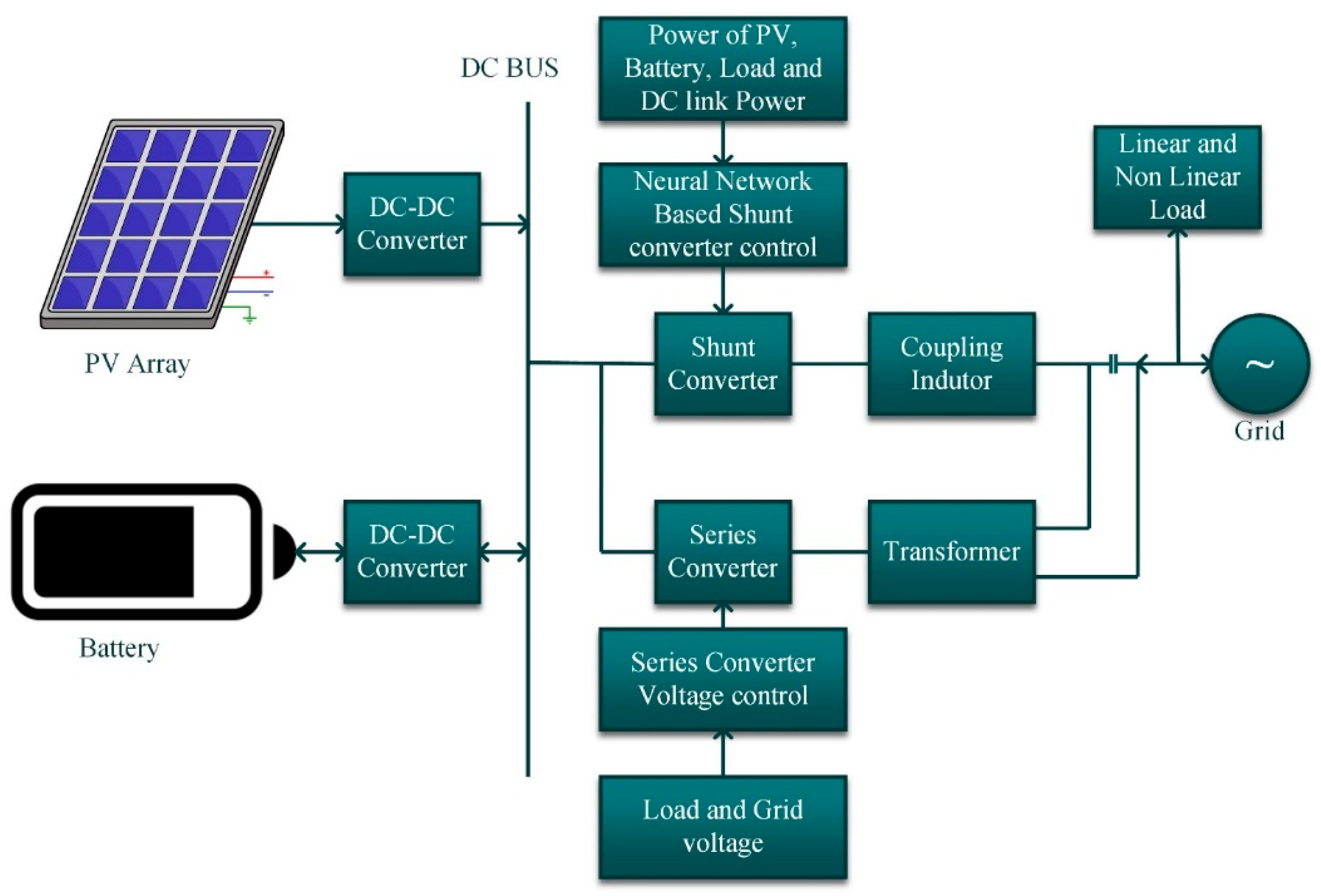
2. Methodology for System Integration with UPQC Configuration

The solar photovoltaic and battery storage system powered UPQC shown in Figure 1 is based on a two-stage UPQC model, a three-phase system designed for grid-connected solar photovoltaic and battery storage systems. A DC-link capacitor is utilised to link the active series and shunt filters. The photovoltaic (PV) panel is connected to the inverter via a step-up DC–DC converter, while the battery is linked directly to the DC link. The series voltage converter regulates the load voltage and mitigates the effects of voltage dips, voltage surges, voltage interruptions, and voltage harmonics. A shunt voltage source converter is used to mitigate line current harmonics caused by load non-linearity. The shunt voltage source is linked to the main power system through coupling reactors. A series-switched transformer connects the series voltage source converter to the main grid. The control logic for a shunt voltage source converter is designed to maximise the output power of the photovoltaic system while minimizing current fluctuations. Under normal operating circumstances, the PV system output transports real power to the loads and the grid and charges BESS. Therefore, the battery storage system can meet the entire demand even when the PV system is not producing power.

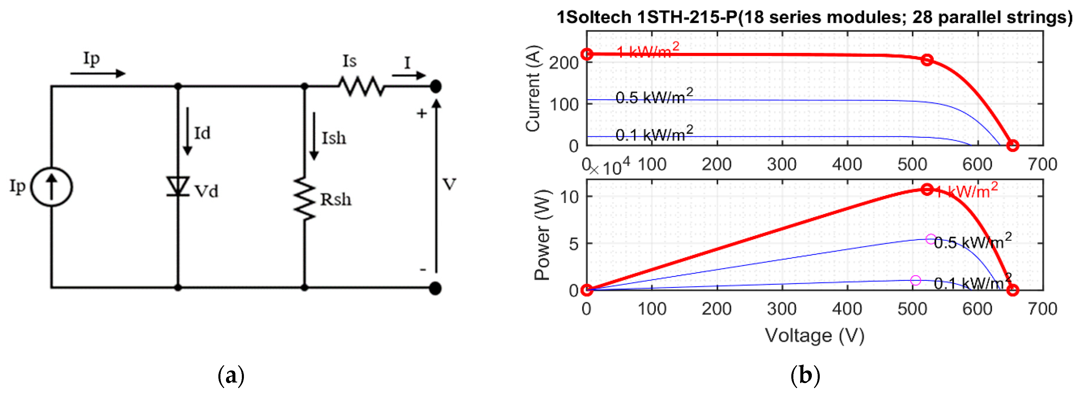
2.1. PV Array Configuration

A solar cell uses the photovoltaic effect to convert sunlight into electricity. Figure 2a shows the basic single diode PV equivalent circuit. The model is constructed using the following mathematical expressions,
I = I p I d I s h
I p = I s c + K i T k T × G 1000
Here, I p and I d represent the photovoltaic current and the diode current, respectively. I s h and I represent the shunt current and the output current, respectively. In Equation (2), I s c , K i , T and G represent short-circuit current, Boltzmann constant, PV cell temperature and irradiance, respectively.
In this work, the MATLAB Simulink PV model library is used. In the PV model, strings of PV modules are linked in parallel. Moreover, each string includes a number of PV modules to achieve the corresponding current, voltage and power values. The PV power of the single model is 213.15 W, 29 V and 7.35 A. In this work, 18 PV modules connected in series and 29 strings connected in parallel are considered. The total power of the PV generator is 107.4 kW, the voltage at the power peak is 522 V and the current at the power peak is 205.8 A. The current, voltage and power characteristics of the considered PV generator are shown in Figure 2b for different irradiation conditions.
The maximum power point tracking algorithm controls the peak power of the photovoltaic system. In this paper, the Perturb and Observe (P & O) procedure is used to track the peak power of the photovoltaic system. P & O is a simple strategy that allows more accurate tracking of the peak power point. The PV voltage ( V p v ) and current ( I p v ) are the input to the peak power point tracking algorithm.
For this approach to work, PV module current and voltage must be measured to estimate module power ( P p v ). Once the operating point reaches the peak power point, the observation and perturbation methods are repeated until the operating point reaches the maximum power point. The algorithm compares the current instantaneous power and voltage to the previous instantaneous power and voltage and predicts the time required to reach the peak power point.
The MPPT voltage of the photovoltaic module is decreased or increased at regular intervals using the P & O algorithm. When a solar module experiences a positive power shift, even a very small voltage fluctuation can affect its performance, and this voltage fluctuation pattern persists. While it is possible to reach the peak power point by reducing disturbances, when a negative shift occurs, the peak power point is a peak power tracking algorithm that disturbs and observes the PWM generator that controls the DC–DC boost converter to extract peak power from the photovoltaic system. The pseudo-code of the MPPT algorithm used is presented in Appendix A.

2.2. PV Array Configuration

In this article, we use the Simulink library battery model. The nominal of the battery is 700 V its nominal capacity is 48 Ah, and the battery type is lithium-ion. The discharge characteristics of the battery under consideration are shown in Figure 3.

2.3. Design of DC–DC Boost Converter for PV Array Integration

The DC–DC boost converter acted as a peak power tracker for the PV system based on control inputs from the peak power point tracking algorithm (perturb and observe). The capacitor and inductor of the DC–DC boost converter were designed based on the following parameters: The input power of the DC–DC boost converter is 107.4   kW (PV rated power), the input voltage of the converter is 522   V (PV voltage), the output voltage of the converter is 700   V (DC link voltage requirement of series and shunt voltage source converter and battery rated voltage), the switching frequency of the converter is 10   kHz , the percentage of inductor current ripple is 1 % and percentage of capacitor voltage ripple is 1 % . The value of capacitor and inductor of DC–DC boost convert is 6668   µ F and 3   mH , respectively.

2.3.1. Capacitor Rating of DC Link

Fluctuations of the modulation value and the system voltage per phase affect the DC link voltage DC ( U d c _ l i n k ); it is recommended that the peak voltage per phase of the three-phase system should be more than twice the DC–DC link voltage as shown in Equation (3)
U d c _ l i n k = V l i n e l i n e × 2 2 γ × 3
V l i n e l i n e is the line voltage and the modulation value γ is assumed to be 1 . For a line voltage of 400   V , the minimum bus voltage requirement is DC 653.1   V . To achieve the operating conditions for the peak power of the PV generator DC–DC under standard test conditions, 700   V is set as the DC bus voltage ( U d c _ l i n k ).
The power required and the voltage level of the DC bus determine the size of the DC-link capacitor. Equation (4) is the energy balance equation for the DC-bus capacitor,
C d c _ l i n k = 3 × I p × V p × γ × t × O f a c t o r 1 2 U d c l i n k r 2 U d c _ l i n k 2
where   O f a c t o r   is the overload factor, V p is the phase voltage, t is the minimum time required to stabilise the voltage after a disturbance of the DC bus voltage, I p is the phase voltage transformer current, and   γ is the factor, that accounts for energy fluctuations during dynamics. The minimum DC link voltage requirement U d c _ l i n k is 653.1   V , the required DC link voltage U d c _ l i n k r is 700   V , the phase current of the shunt voltage source converter is 132   A , the stabilisation time is 30   ms , the overload factor is 1.2 , the change in dynamic energy is 10 % , and the capacitor value of the DC link is 6668   μ F .

2.3.2. Coupling Inductor of the Shunt Voltage Source Converter

The values of DC-intermediate circuit voltage, switching frequency and ripple current effect the size of the coupling inductor of a shunt voltage source converter. We calculate the value of the coupling inductor using Equation (5),
L c l = U d c l i n k r × γ × 3 I l _ r i p p l e × F s s w × O f a c t o r × 12
Here, the switching frequency of the shunt voltage source converter F s s w is 10 kHz, I l _ r i p p l e is the ripple current in the coupling inductance and is 20% of the I p . γ = 1 , O f a c t o r = 1.2 , U d c l i n k r = 700   V and I l _ r i p p l e is 6.23   A , and the value of coupling inductance is 1.39   mH .

2.3.3. Injection Transformer for the Series Voltage Source Converter

The photovoltaic solar system and battery storage system are designed for sag or swell threshold of 0.2   pu or 46   V / phase , when the DC link voltage is 700   V , the series voltage source transformer only needs to feed 46   V / phase , resulting in a low modulation index for the series compensator. One must keep the modulation index of the series voltage source converter as close to unity as possible to minimise harmonic distortion. As a result, a series transformer is used with a turn ratio expressed as follows,
T r a t i o = V p p V s v s c
Here T r a t i o is the transformation ratio of the transformer,   V p p is the phase voltage, and V s v s c is the voltage of the series voltage converter. In this work,   V p p = 230   V , V s v s c = 46 gives a transformer ratio of 5 . The feed transformer rating for the series voltage source converter is given by Equation (7),
R I T = 3 × V s v s c × I s v s c _ s a g
Here, R I T is the power of the injection transformer rating, I s v s c _ s a g is the sag current of the series voltage transformer. In this work, V S V S C = 46   V , I s v s c _ s a g = 30   A which gives a feeder transformer power of 4140   VA .

3. Proposed Control Logic

Series and shunt voltage source converters are both essential components of the PV battery storage system sourced UPQC. By using the shunt voltage source converter, the system is intelligent to correct the quality of power problems of the load such as harmonics and reactive power. UPQC based on PV solar systems and battery storage system uses shunt voltage source converter for power supply in addition to the PV solar system. The neural network concept is used in the shunt voltage source converter to generate a reference current that provides active power and mitigates the harmonic problem owing to the non-linearity of the load and extreme swell and sag. The serial voltage source converter keeps the load from grid-side power quality problems such as voltage fluctuations and sag by adding a suitable voltage in phase with the grid voltage.

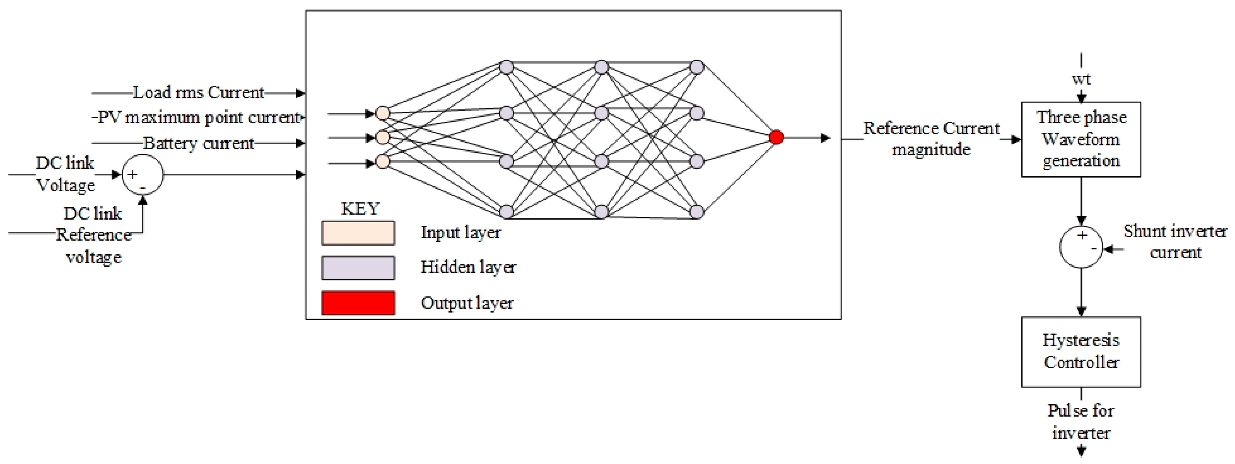
3.1. Control Logic of Shunt Voltage Source Converter

As shown in Figure 4, the inputs of the neural network are the current generated by the photovoltaic system, the root mean square current of the load, the leakage current from the DC-link voltage control, and the battery current. The output of the neural network is a reference for the current. The amplitude of the reference current is multiplied by three-phase sine waves in an a-b-c synchronisation frame and then compared to the shunt voltage source converter current. The hysteresis controller processes the compensation current and generates the pulse for the voltage source shunt converter; it regulates the current pumped into the grid and mitigates the harmonic disturbances caused by the non-linear load on the grid side.

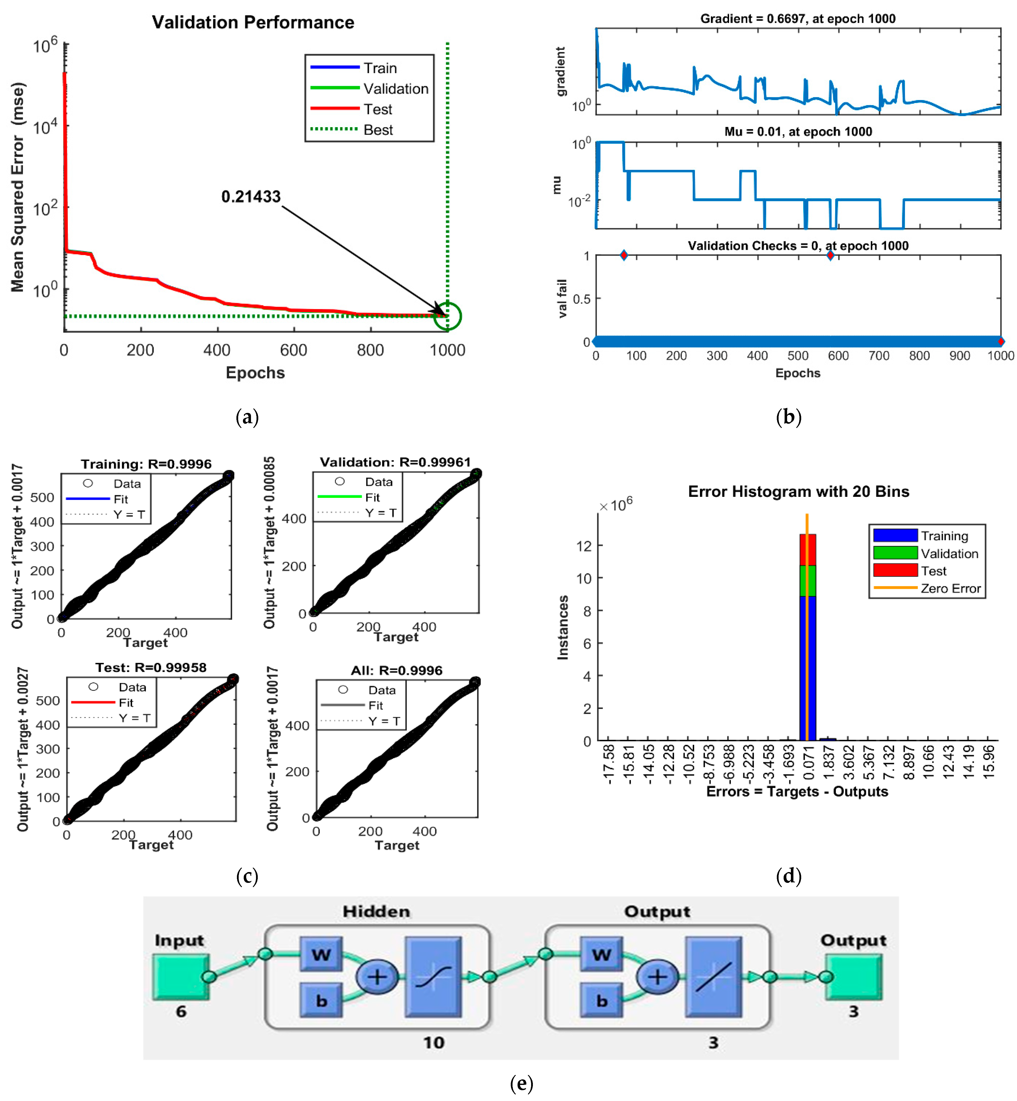
Training and Validation of Artificial Neural Network

To effectively generate the reference signal, this work uses an artificial neural network trained with the Levenberg-Marquardt backpropagation. The training is performed using Matlab software. First, a total of 4.2 × 10 6 data are collected from the grid-connected photovoltaic two-level UPQC model designed in Matlab/Simulink software. The Matlab neural network training software tool is used to train the ANN, using the collected data. By default, the neural network fitting tool considers 70 % of samples for training. Here, the network is fitted according to its error, 15 % of the samples are used for validation to measure the simplification of the net and stop training when the simplification stops improving, and 15 % of the samples are used for testing. A total of 1000 iterations were considered during the training process. Figure 5 shows the validation performance, training state, error histogram, and regression plots. Figure 5a shows the best validation performance at the 1000 th     iteration is 0.21433 . Variation of gradient during training is shown in Figure 5b. From the regression plots (Figure 5c), it can be seen that the correlation between the outputs and the value of the target for the training, validation and testing is close to 1. The error histogram of the target and outputs are depicted in Figure 5d. The final trained neural network controller is shown in Figure 5e.

3.2. Control Logic of Series Voltage Source Converter

The control technique of the serial voltage source converter includes in-phase compensation, pre-compensation, and energy optimisation. In this study, a minimum injection voltage is achieved by using a serial voltage source converter to add a voltage in phase with the mains voltage. The series voltage source converter has a control structure as shown in Figure 6, It helps maintain the rated load voltage when the line voltage is unstable. In this case, the series voltage source compensator produces an output voltage that is unstable. In this case, the series voltage source compensator produces an output voltage that is out of phase with the disturbance and corrects the problem.
A phase-locked loop (PLL) is utilised to excerpt the important component of the point of common coupling (PCC) voltage, which is then used to generate the dq-0 reference axis. The PLL determines the phase and frequency of the PCC voltage, which is then used to generate a reference load voltage. By converting the input voltages from the PCC and the load voltages, a d-q-0 range is generated. The peak value of the load reference voltage is equal to the value of the d-axis component of the load reference voltage, as the load reference voltage must be phase-locked to the PCC voltage. On the q-axis, the components are kept constant at zero. The PCC voltage is subtracted from the load reference voltage to obtain the series compensator voltage. The variance between the PCC voltage and the load voltage is used to calculate the real voltages of the series compensators. To generate accurate reference signals, the voltage difference between the voltage of the reference and real series compensators must be made processed via PI controller; these signals are then utilised to produce control signals for the series compensators via an a-b-c converter for pulse width modulation (PWM).

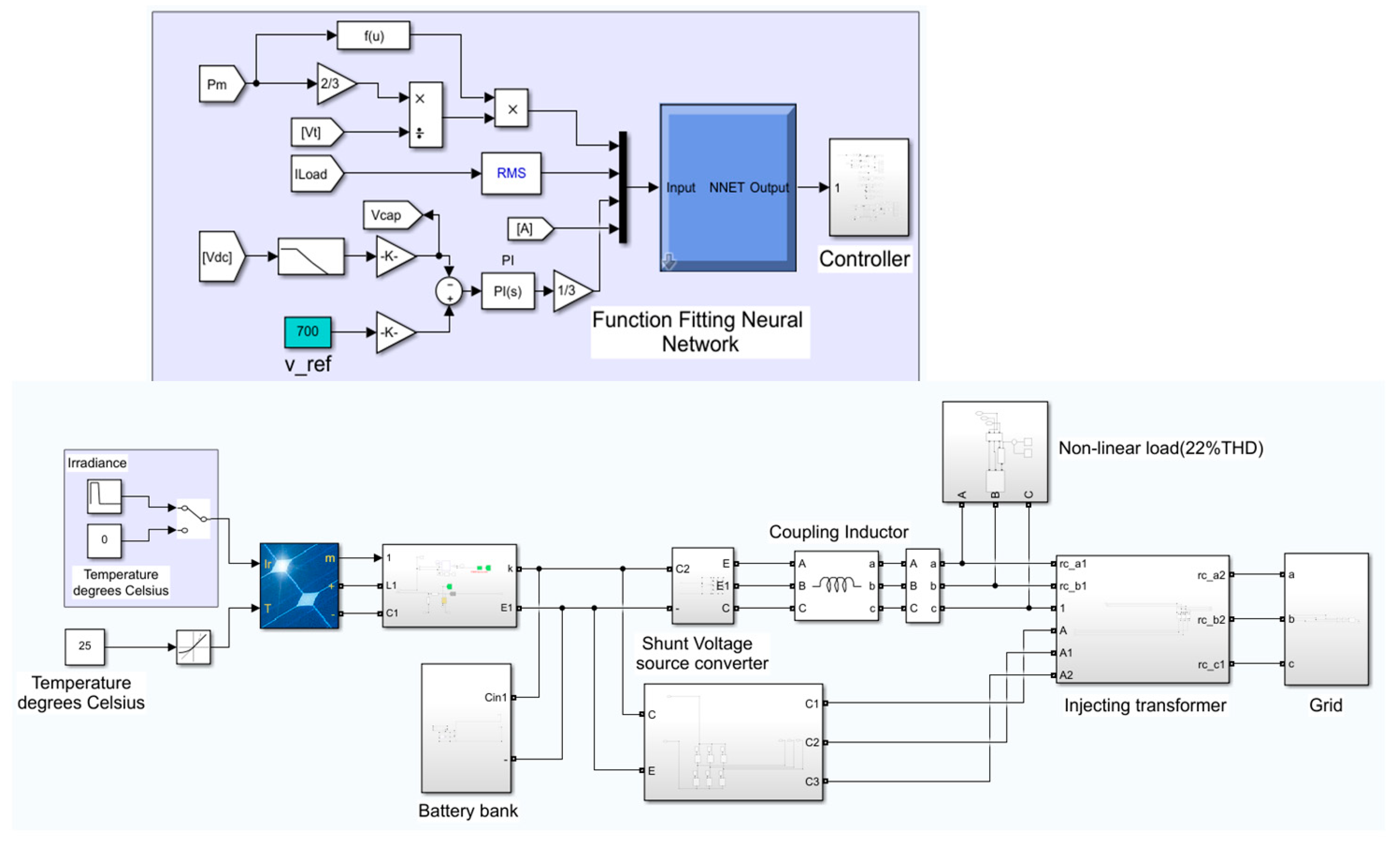
4. Matlab/Simulink Model Details

In this segment, to validate the performance of the proposed control method, MATLAB/Simulink software is used to simulate the dynamic and steady-state performance of grid-connected solar PV systems and battery storage sourced UPQC model. In the simulation, a three-phase diode bridge rectifier with R-L load is used as a non-linear load (22% THD). The step size of the solver used in the simulation is 1 × 10⁻⁶ s. To handle these dynamic situations, the system has to cope with PCC voltage variations and solar irradiance changes. The MATLAB/Simulink simulation is shown in Figure 7.

5. Discussion

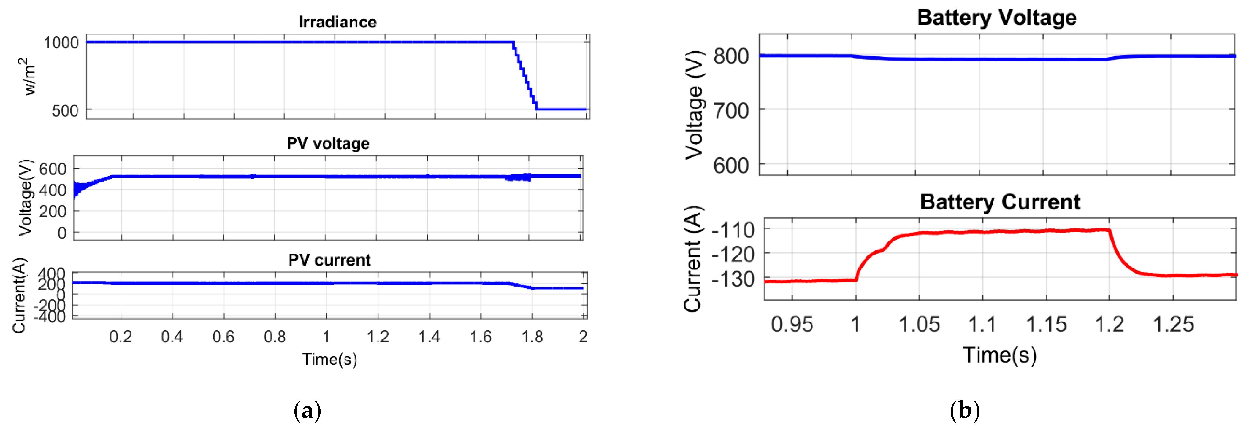
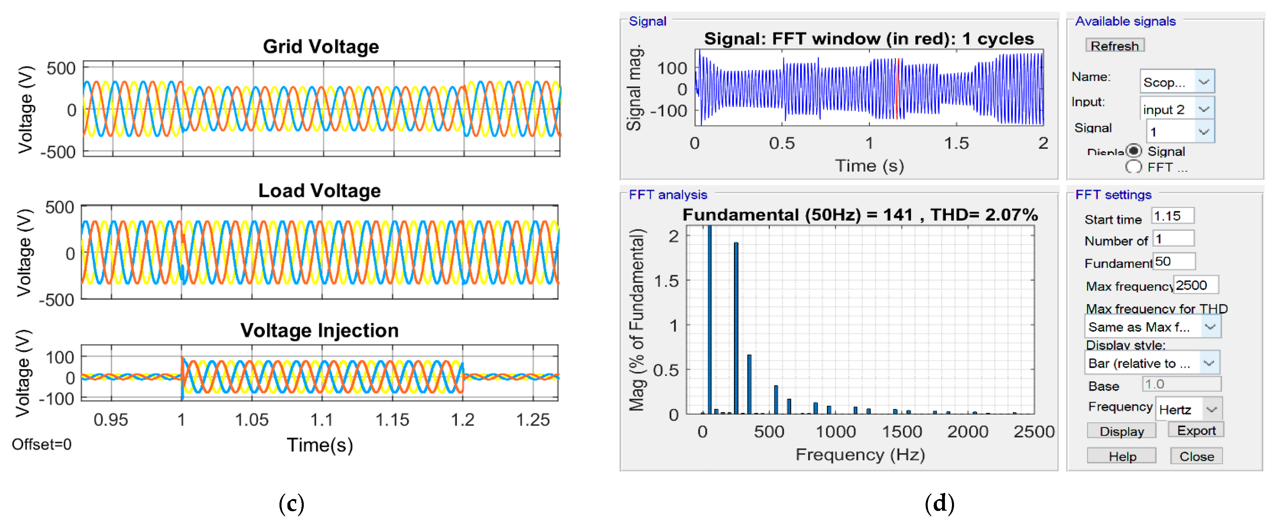
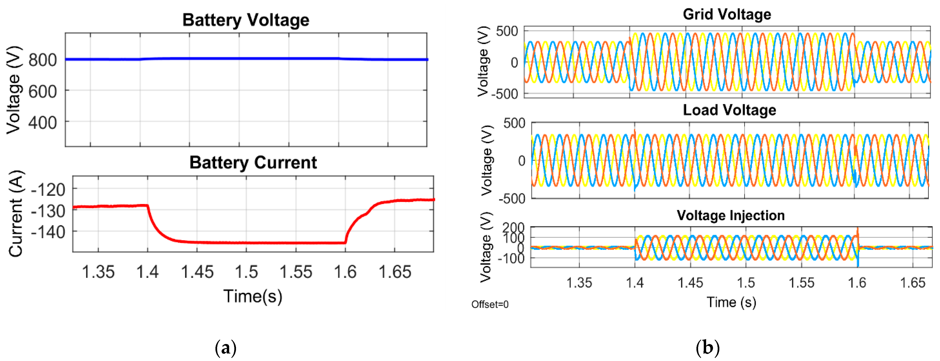
5.1. Results Analysis of the Proposed System under Voltage Sag and Voltage Swell Condition

This section discusses the voltage dips and swells analyses for the PV solar system and the battery-based UPQC. The temperature and photovoltaic irradiance are held at constant values of 25 °C and 1000 W/m2, respectively. The response of the system parameters to the voltage drop is shown in Figure 8; these include photovoltaic module irradiance, PV current, PV voltage, photovoltaic power, battery voltage, battery current, grid voltage, load voltage, and voltage added into the system through the series voltage converter. From 1 s to 1.2 s, there is a voltage drop of 0.2 pu. The series voltage source converter injects a voltage in the contradictory phase of the disturbance to uphold the load voltage at its nominal value when the line voltage is disturbed.
Figure 9 depicts the response of the system parameters under voltage swell conditions, such as irradiance of PV panel, PV voltage, PV current, PV power, battery voltage, battery current, grid voltage, load voltage, and the voltage added into the system through the series voltage source compensator. The voltage fluctuations of 0.2 pu are generated at 1.4 s to 1.6 s. The series voltage source converter injects a voltage in the contradictory phase of the disturbance to uphold the load voltage at its nominal value when the line voltage is disturbed.

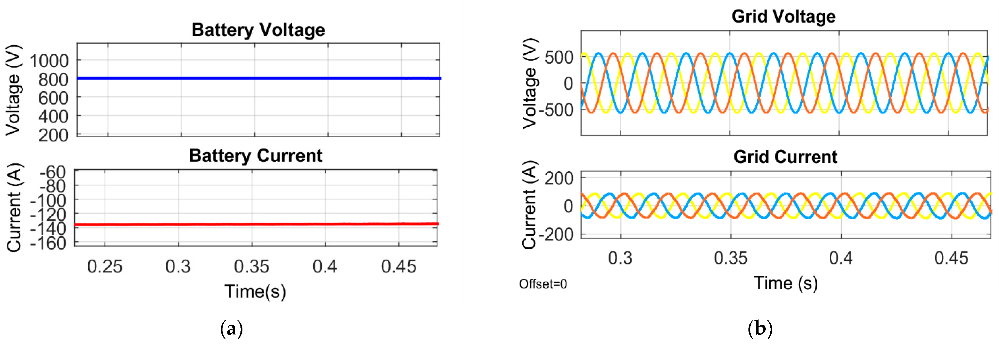
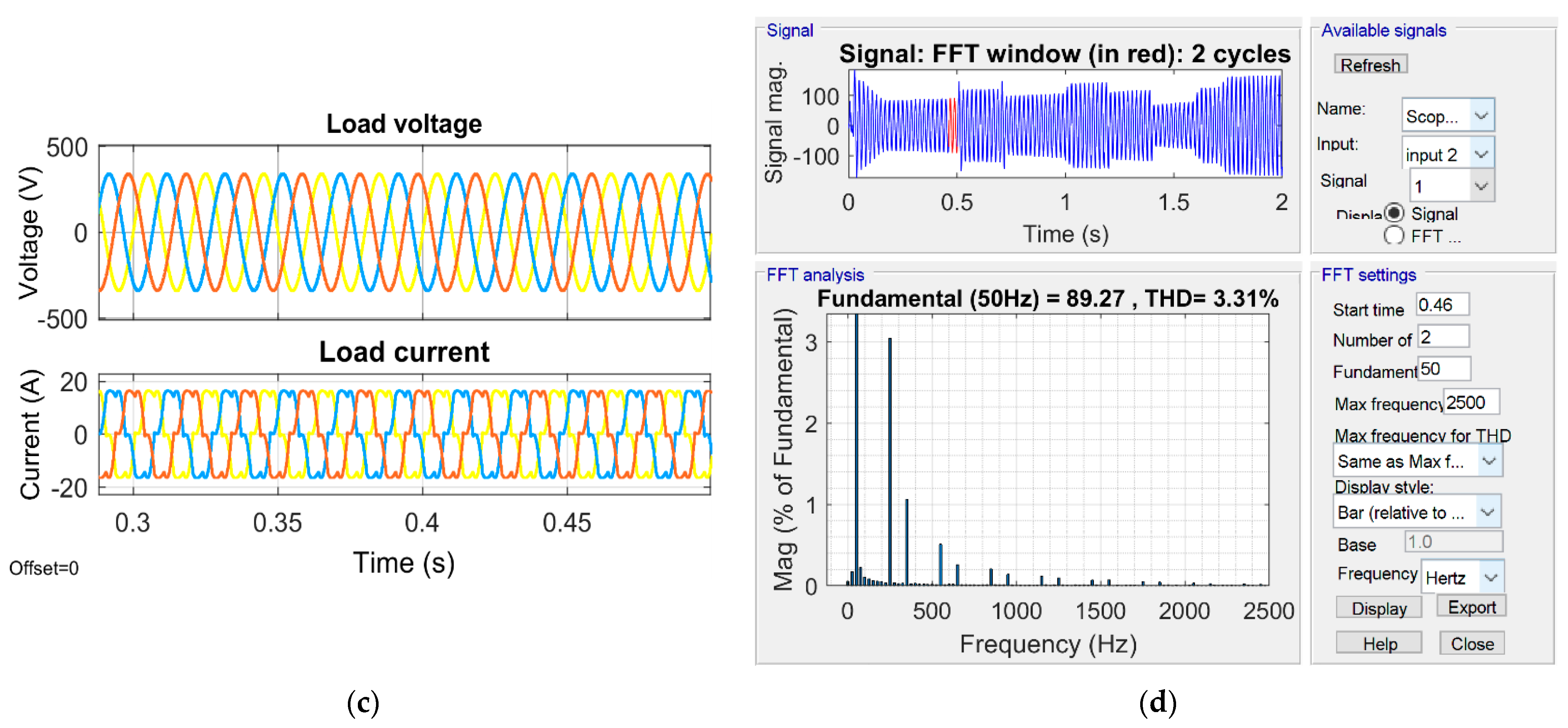
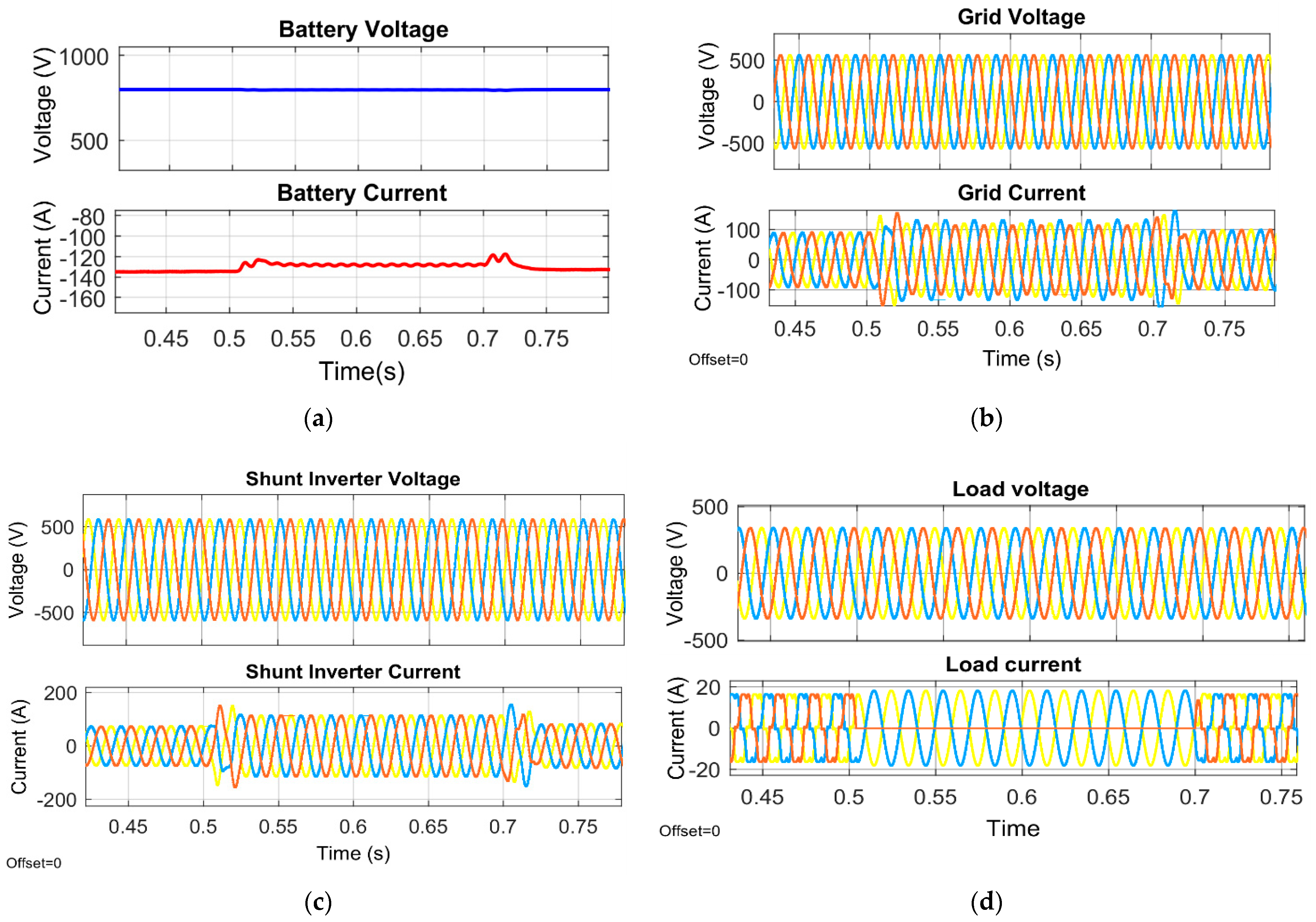
5.2. Results Analysis of the Proposed System under Non-linear Load and Unbalanced Load

In this section, the analyses of the PV solar system and the battery-based UPQC under load unbalanced and non-linear conditions are presented. The PV solar temperature and radiation were kept at 25 °C and 1000 W/m2, respectively. Figure 10 shows the response of system parameters under non-linear load conditions, such as PV panel irradiance, PV voltage, PV current, PV power, battery voltage, battery current, belt voltage and current, load voltage and current, and shunt inverter voltage and current. The non-linear load conditions are generated at 0.3 s to 0.5 s. Under these conditions, the system current remains sinusoidal thanks to the shunt voltage source converter, mitigating the harmonics caused by the non-linear load.
Figure 11 depicts the response of the system parameters under load unbalanced conditions. Parameters such as battery voltage, battery current, line current, line voltage load voltage and load current, and shunt inverter voltage and current are examined. The unbalanced load conditions are generated at 0.5 to 0.7 s by disconnecting one line of the load. In this condition, the line current remains sinusoidal due to the shunt voltage source converter and mitigates the harmonics caused by the unbalanced load.

5.3. Comparison of the Proposed Neural Network Controller with PQ and SRF Control of Shunt Converter

In this section, the proposed neural network-based control of the shunt converter is compared with the PQ [10] and SRF [12] controls.
The total harmonic distortion of the grid current for different irradiation conditions is compared and presented in Table 1. From the analysis of the results, it is found that the proposed neural network controller meets the IEEE standards for total harmonic distortion at high and low irradiance conditions and that PQ and the SRF controller do not meet the IEEE standard under low irradiance conditions.
The total harmonic distortion of the grid current under different voltage drop conditions is compared and shown in Table 2. From the analysis of the results, it can be seen that the new proposed controller complies with the IEEE standard for total harmonic distortion and is always below 5%, but PQ and the SRF controller do not comply with the IEEE standard for high voltage drop.
The total harmonic distortion of the grid current under various voltage swell conditions is compared and shown in Table 3. From the examination of the results, the proposed neural network controller complies with the IEEE standard for total harmonic distortion and is always below 5%, while PQ and the SRF controller do not comply with the IEEE standard for high voltage swell conditions.
The total harmonic distortion of the line current under various unbalanced load conditions is compared and shown in Table 4. From the examination of the results, the proposed neural network controller meets the IEEE-519 standard for total harmonic distortion and is always below 5%, while PQ and the SRF controller do not meet the IEEE standard for some unbalanced load conditions.

6. Conclusions

Using variable irradiance, grid voltage fluctuations and non-linear and unbalanced load conditions of the three-phase solar PV and battery storage system based on UPQC architecture and dynamic performance were investigated. Non-linear load harmonics are reduced by the proposed Artificial Neural Network control. The obtained results show that the harmonic distortion of the grid current is within the standard limits of IEEE-519 in all test scenarios (less than 5%). When the irradiation, voltage and load unbalance are varied, the system remains stable. The introduction of neural network control has increased the performance of the d-q control, particularly under unbalanced circumstances; this model can be easily implemented with a simple and cheaper microcontroller, saving the cost of developing complex hardware to achieve similar efficiency of results. By combining distributed generation with power quality improvement, photovoltaics, and battery storage systems, UPQC is a promising option for the current distribution system. The idea proposed in this article is still expandable. Future work may attempt to implement the proposed model with a three- or five-level grid-connected photovoltaic battery UPQC system and also latest optimisation can be used for training the neural network for getting better power quality results.

Author Contributions

Conceptualization, O.E.O.; Formal analysis, K.P.; Methodology, O.E.O.; Software, O.E.O.; Supervision, Z.-H.L.; Writing—original draft, O.E.O.; Writing—review and editing, M.X. and A.J.R. All authors have read and agreed to the published version of the manuscript.

Funding

This work was sponsored by the Program of Foundation of Science and Technology Commission of Shanghai Municipality (22dz1206005, 22dz1204202), National Natural Science Foundation of China (12172228, 11572187), and Natural Science Foundation of Shanghai (22ZR1444400).

Conflicts of Interest

The authors declare no conflict of interest.

Nomenclature

UPQCUnified Power Quality Conditioners
ANNArtificial Neural Network
P&OPerturb and Observe
THDTotal Harmonic Distortion
SRFSynchronous reference frame theory
ANFISAdaptive Neuro-Fuzzy Inference system
FCFuel cell
SMESSuperconducting Magnetic Energy Storage System
DCDirect Current
BESSBattery Energy Storage System
PLLPhased Locked Loop
PhotovoltaicsPV
PCCPoint of common coupling
PWMPulse width modulation
IvPhotovoltaics current
IdDiode Current
IshShunt Current
IOutput current
IscShort circuit current
TTemperature
GIrradiance
KiBoltzmann Constant
Vline_lineLine to Line voltage of the grid
Udc_linkDc link Voltage of the Inverter
OfactorOverload factor
Vpp or VppPhase voltage of the grid
IpPhase current of the transformer
Il_rippleripple current of the filter inductor
FsswInverter switching frequency
VsvscVoltage of the series voltage converter
Isvsc_sagCurrent of the series voltage converter
TratioTransformation ratio of the transformer

Appendix A

The seudo code briefly descrides the implementation of the Perturb and Observe maximum power point tracking algorithm, used in this work. In the algorithm, fastly, the string voltage and current are sampled then the power is calculated by multiplying the voltage and current. The algorithm compares the values of the current power and voltage with the previuos power and voltage then makes adjustments to the reference voltage according to the condition as shown in the seudo code below.
Algorithm A1: Perturb and Observe MPPT Algorithm
1:procedure  P & O M P P T V s t , I s t , V r e f
2: V s t , n   V s t Sample   the   string   voltage   and   current Calculate   the   string   power
3: I s t , n   I s t
4: P s t , n   V s t , n × I s t , n
5:If  f i n i t   False   then Check   if   the   initialization   has   been   performed   or   not , If   not ,   reduce   the   string   voltage   reference   then   set   the   initialization   flag   to   True  
6:   V r e f V s t , n S min
7:   f i n i t T r u e
8:else
9:  If  P s t , n > P s t , n 1   then Check   if   the   panel   power   and   voltage   is   increased   or   not , i f   V s t d P s t >   0 ,   increase   V r e f   by   the   step   size   S min i f   V s t d P s t <   0 ,   decrease   V r e f   by   the   step   size   S min
10:  If  V s t , n > V s t , n 1   then
11:     V r e f V r e f + S min
12:  else
13:     V r e f V r e f S min
14:  end if
15:else
16:  If  V s t , n > V s t , n 1   then Check   if   the   panel   power   and   voltage   is   decreased   or   not , i f   V s t d P s t <   0 ,   decrease   V r e f   by   the   step   size   S min i f   V s t d P s t >   0 ,   increase   V r e f   by   the   step   size   S min
17:     V r e f V r e f S min
18:  else
18:     V r e f V r e f + S min
19:  end if
20:end if
21:end if
22: V s t , n 1 V s t , n Update   the   previous   voltage   sample   by   the   present   voltage   sample Update   the   previous   power   value   by   the   present   power   value .
23: P s t , n 1 P s t , n
24:return  V r e f  
25:end procedure

References

  1. IEEE Std 1159; IEEE Recommended Practice for Monitoring Electric Power Quality. Institute of Electrical and Electronics Engineers: Piscataway, NJ, USA, 2009; Volume 10, pp. 1–81. [CrossRef]
  2. Javadi, A.; Woodward, L.; Al-Haddad, K. Real-Time Implementation of a Three-Phase THSeAF Based on a VSC and a P+R Controller to Improve the Power Quality of Weak Distribution Systems. IEEE Trans. Power Electron. 2018, 33, 2073–2082. [Google Scholar] [CrossRef]
  3. Javadi, A.; Hamadi, A.; Woodward, L.; Al-Haddad, K. Experimental Investigation on a Hybrid Series Active Power Compensator to Improve Power Quality of Typical Households. IEEE Trans. Ind. Electron. 2016, 63, 4849–4859. [Google Scholar] [CrossRef]
  4. Mansor, M.A.; Othman, M.M.; Musirin, I.; Noor, S.Z.M. Dynamic voltage restorer (DVR) in a complex voltage disturbance compensation. Int. J. Power Electron. Drive Syst. 2019, 10, 2222–2230. [Google Scholar] [CrossRef]
  5. Ghosh, A.; Ledwich, G. Compensation of distribution system voltage using DVR. IEEE Trans. Power Deliv. 2002, 17, 1030–1036. [Google Scholar] [CrossRef]
  6. Jothibasu, S.; Mishra, M.K. A Control Scheme for Storageless DVR Based on Characterization of Voltage Sags. IEEE Trans. Power Deliv. 2014, 29, 2261–2269. [Google Scholar] [CrossRef]
  7. Farooqi, A.; Othman, M.M.; Abidin, A.F.; Sulaiman, S.I.; Radzi, M.A.M. Mitigation of power quality problems using series active filter in a microgrid system. Int. J. Power Electron. Drive Syst. 2019, 10, 2245–2253. [Google Scholar] [CrossRef]
  8. Kumar, C.; Mishra, M.K. Operation and Control of an Improved Performance Interactive DSTATCOM. IEEE Trans. Ind. Electron. 2015, 62, 6024–6034. [Google Scholar] [CrossRef]
  9. Hoon, Y.; Radzi, M.A.M.; Hassan, M.K.; Mailah, N.F. Control Algorithms of Shunt Active Power Filter for Harmonics Mitigation: A Review. Energies 2017, 10, 2038. [Google Scholar] [CrossRef]
  10. Campanhol, L.B.G.; da Silva, S.A.O.; Goedtel, A. Application of shunt active power filter for harmonic reduction and reactive power compensation in three-phase four-wire systems. IET Power Electron. 2014, 7, 2825–2836. [Google Scholar] [CrossRef]
  11. Sundarabalan, C.K.; Puttagunta, Y.; Vignesh, V. Fuel cell integrated unified power quality conditioner for voltage and current reparation in four-wire distribution grid. IET Smart Grid 2019, 2, 60–68. [Google Scholar] [CrossRef]
  12. Devassy, S.; Singh, B. Design and performance analysis of three-phase solar PV integrated UPQC. In Proceedings of the 2016 IEEE 6th International Conference on Power Systems, New Delhi, India, 4–6 March 2016. [Google Scholar] [CrossRef]
  13. Gee, A.M.; Robinson, F.; Yuan, W. A Superconducting Magnetic Energy Storage-Emulator/Battery Supported Dynamic Voltage Restorer. IEEE Trans. Energy Convers. 2017, 32, 55–64. [Google Scholar] [CrossRef]
  14. Kollimalla, S.K.; Mishra, M.K.; Narasamma, N.L. Design and Analysis of Novel Control Strategy for Battery and Supercapacitor Storage System. IEEE Trans. Sustain. Energy 2014, 5, 1137–1144. [Google Scholar] [CrossRef]
  15. Karanki, S.B.; Geddada, N.; Mishra, M.K.; Kumar, B.K. A Modified Three-Phase Four-Wire UPQC Topology with Reduced DC-Link Voltage Rating. IEEE Trans. Ind. Electron. 2013, 60, 3555–3566. [Google Scholar] [CrossRef]
  16. Teke, A.; Saribulut, L.; Tumay, M. A Novel Reference Signal Generation Method for Power-Quality Improvement of Unified Power-Quality Conditioner. IEEE Trans. Power Deliv. 2011, 26, 2205–2214. [Google Scholar] [CrossRef]
  17. Kinhal, V.G.; Agarwal, P.; Gupta, H.O. Performance Investigation of Neural-Network-Based Unified Power-Quality Conditioner. IEEE Trans. Power Deliv. 2011, 26, 431–437. [Google Scholar] [CrossRef]
  18. Campanhol, L.B.G.; da Silva, S.A.O.; de Oliveira, A.A.; Bacon, V.D. Power Flow and Stability Analyses of a Multifunctional Distributed Generation System Integrating a Photovoltaic System with Unified Power Quality Conditioner. IEEE Trans. Power Electron. 2019, 34, 6241–6256. [Google Scholar] [CrossRef]
  19. Hasan, K.; Othman, M.M.; Rahman, N.F.A.; Hannan, M.A.; Musirin, I. Significant implication of unified power quality conditioner in power quality problems mitigation. Int. J. Power Electron. Drive Syst. 2019, 10, 2231–2237. [Google Scholar] [CrossRef]
  20. Han, B.; Bae, B.; Kim, H.; Baek, S. Combined Operation of Unified Power-Quality Conditioner with Distributed Generation. IEEE Trans. Power Deliv. 2006, 21, 330–338. [Google Scholar] [CrossRef]
  21. Guerrero, J.M.; Loh, P.C.; Lee, T.-L.; Chandorkar, M. Advanced Control Architectures for Intelligent Microgrids—Part II: Power Quality, Energy Storage, and AC/DC Microgrids. IEEE Trans. Ind. Electron. 2013, 60, 1263–1270. [Google Scholar] [CrossRef]
  22. Khadem, S.K.; Basu, M.; Conlon, M.F. Intelligent Islanding and Seamless Reconnection Technique for Microgrid with UPQC. IEEE J. Emerg. Sel. Top. Power Electron. 2015, 3, 483–492. [Google Scholar] [CrossRef]
  23. Xiang, H.; Chen, B.; Yang, M.; Li, C. Altitude measurement based on characteristics reversal by deep neural network for VHF radar. IET Radar Sonar Navig. 2019, 13, 98–103. [Google Scholar] [CrossRef]
  24. Agarwal, R.K.; Hussain, I.; Singh, B. Application of LMS-Based NN Structure for Power Quality Enhancement in a Distribution Network under Abnormal Conditions. IEEE Trans. Neural Netw. Learn. Syst. 2018, 29, 1598–1607. [Google Scholar] [CrossRef]
  25. Kumar, A.; Mishra, V.; Ranjan, R. Low Voltage Ride through Capability and Power Quality Improvement in Grid Connected PV System Using ANN Tuned UPQC. In Proceedings of the 2021 IEEE 4th International Conference on Computing, Power and Communication Technologies (GUCON), Kuala Lumpur, Malaysia, 24–26 September 2021. [Google Scholar] [CrossRef]
  26. Gupta, N.; Institute of Engineering & Technology. Artificial neural network and synchrosqueezing wavelet transform based control of power quality events in distributed system integrated with distributed generation sources. Int. Trans. Electr. Energy Syst. 2021, 31, e12824. [Google Scholar] [CrossRef]
  27. Kumar, A.S.; Rajasekar, S.; Raj, P.A.-D.-V. Power Quality Profile Enhancement of Utility Connected Microgrid System Using ANFIS-UPQC. Procedia Technol. 2015, 21, 112–119. [Google Scholar] [CrossRef]
  28. Dheeban, S.; Selvan, N.M. ANFIS-based Power Quality Improvement by Photovoltaic Integrated UPQC at Distribution System. IETE J. Res. 2021, 1–19. [Google Scholar] [CrossRef]
Figure 1. Block Diagram of the Proposed work.
Energies 15 06825 g001
Figure 2. (a) Fundamental single diode equivalent circuit; (b) Current-Voltage and Power-Voltage characteristics of the considered PV array for different irradiance.
Energies 15 06825 g002
Figure 3. Discharging characteristics of the considered lithium-ion.
Energies 15 06825 g003
Figure 4. Shunt voltage source converter control logic model.
Energies 15 06825 g004
Figure 5. (a) Validation performance, (b) Training state, (c) Regression plot, (d) Error histogram, (e) Final trained neural network.
Energies 15 06825 g005
Figure 6. Series voltage source converter control logic.
Energies 15 06825 g006
Figure 7. Matlab/Simulink simulation model of the proposed control technique.
Energies 15 06825 g007
Figure 8. Response of the system parameters under voltage sag conditions. (a) Irradiance, PV voltage, power and current, (b) Battery voltage and current under voltage sag condition (c) Grid voltage, Load voltage and voltage injection under voltage sag condition (d) THD under voltage sag condition.
Energies 15 06825 g008aEnergies 15 06825 g008b
Figure 9. Response of the system parameters under voltage swell conditions. (a) Battery voltage and current under voltage sag condition (b) Grid voltage, Load voltage and voltage injection during voltage swell condition (c) THD during voltage swell condition.
Energies 15 06825 g009aEnergies 15 06825 g009b
Figure 10. Response of the system parameters under non-linear load conditions. (a) Battery voltage and current under non-linear load condition, (b) Grid voltage and current under non-linear load condition, (c) Load voltage and current under non-linear load condition, and (d) THD under non-linear load condition.
Energies 15 06825 g010aEnergies 15 06825 g010b
Figure 11. Response of the system parameters under unbalanced load conditions, (a) Battery voltage and current under unbalanced load conditions, (b) Grid voltage and current under unbalanced load conditions (c) Shunt inverter voltage and current under unbalanced load conditions, (d) Load voltage and current under unbalanced load conditions, (e) THD under unbalanced load conditions.
Energies 15 06825 g011aEnergies 15 06825 g011b
Table 1. Comparisons Grid current THD for NN controller with PQ and SRF control for various irradiance conditions.
Irradiance (W/m2)THD of the Grid Current (%)
PQ Control
[10]
SRF Control
[12]
NN Control
10004.64.22.07
8004.754.362.8
5004.894.863.5
3005.35.13.9
1005.95.54.2
Table 2. Comparisons Grid current THD for NN controller with PQ and SRF control for various voltage sag conditions.
Voltage Sag (%)THD of the Grid Current (%)
PQ Control
[10]
SRF Control
[12]
NN Control
54.324.212.75
104.514.422.9
154.584.713.1
205.455.193.4
305.955.643.7
Table 3. Comparisons Grid current THD for NN controller with PQ and SRF control for various voltage swell conditions.
Voltage Swell (%)THD of the Grid Current (%)
PQ Control
[10]
SRF Control
[12]
NN Control
54.454.362.8
104.624.412.97
154.814.693.21
205.254.893.39
305.455.153.58
Table 4. Comparisons Grid current THD for NN controller with PQ and SRF control for various voltage unbalanced load conditions.
Unbalanced Load ConditionsTHD of the Grid Current (%)
PQ Control
[10]
SRF Control
[12]
NN Control
Phase A open5.054.893.31
Phase B open5.125.013.45
Phase C open4.955.063.35
Publisher’s Note: MDPI stays neutral with regard to jurisdictional claims in published maps and institutional affiliations.

