
Static Concentrator Photovoltaics Module for Electric Vehicle Applications Based on Compound Parabolic Concentrator


1
Department of Information and Communication Engineering, Myongji University, 116 Myongji-ro, Cheoin-gu, Yongin 17058, Gyeonggi-do, Korea
2
Faculty of Electrical and Electronics Engineering, Phenikaa University, Yen Nghia, Ha Dong, Hanoi 12116, Vietnam
*
Authors to whom correspondence should be addressed.
Energies 2022, 15(19), 6951; https://0-doi-org.brum.beds.ac.uk/10.3390/en15196951
Submission received: 15 August 2022
/
Revised: 8 September 2022
/
Accepted: 9 September 2022
/
Published: 22 September 2022
(This article belongs to the Special Issue Solar Photovoltaics and Solar Power Plants)
Abstract
:Electric vehicles (EVs) and photovoltaics (PVs) are new technologies that will play an important role in the transportation industry over the next decade. Using solar panels on the roofs of cars is one of the simplest ways to reduce fuel costs and increase the mobility of electric vehicles. Solar electric cars can be charged anywhere under the Sun without additional infrastructure, but the problem is the size of the solar panel is limited on the roof and the electricity conversion efficiency of the panel is only 15% to 20%. This means they will not provide significant electricity to EVs. An effective way to increase efficiency is to utilize multi-junction solar cells with concentrator photovoltaic (CPV) technology. The challenge is that the moving sun-tracking mechanism will reduce the stability of the vehicle structure. To solve this issue, in this research, we present a static concentrator photovoltaic system for electric vehicles. This structure is more stable and simpler than CPV systems using sun-tracking mechanisms and thus suitable for car roof application. The CPV system includes solid compound parabolic concentrators (CPCs), three-junction solar cells, and a crystalline Si cell panel. This structure allows for the manufacture of a static CPV with a geometrical concentration ratio of 4× for three-junction cells. The simulation results showed that the module can achieve 25% annual efficiency. Moreover, it can be flexible to meet the requirements of car roof application.
1. Introduction
After a decade of rapid growth, in 2020, global electric car stock hit the 10 million mark, which represented a 43% increase over 2019 and a 1% stock share [1]. Most car manufacturers already have their own electric models, and the recent energy crisis has caused demand for electric vehicles to skyrocket. Although electric vehicles have many outstanding advantages over vehicles that use internal combustion engines, one challenge associated with electric vehicles is the distribution of charging stations. Major car manufacturers not only produce vehicles but also continually expand the availability of their charging station systems to attract more customers. Although the number of charging stations has increased rapidly, it will likely not be enough for the growth of the number of cars sold. Moreover, fast-charging stations require huge capacity [2], and there is a danger of overload when many vehicles are charging at the same time [3]. It is for these reasons that much research and many start-up projects focus on solar cars.
When a car can charge itself by relying on a solar panel on the car roof, the requirement for charging stations can be diminished. For example, Hyundai has revealed its new Sonata, complete with a built-in solar panel, and they estimate that, with six hours of charging in direct sunlight per day, the Sonata Hybrid can gain an extra 1300 km of electric driving per year, which equates to an average increase of 3.5 km/day [4]. With 70% of passenger cars traveling less than 30 km/day [5] on average, a solar panel on a commercial vehicle can help electric vehicles reduce energy consumption by 10–12% per day. Dutch startup company Lightyear was set to launch a solar-powered car in 2019. They focused on increasing the solar panel area on the car by 5 m2, improving the engine efficiency, aerodynamics, and reducing the weight of the car. They tested and estimated the car could run an extra 70 km per day, however, new products are experimental and need more time for mass production [6].
In all vehicles, due to the size limit of the roof area, we need to increase the photovoltaic conversion efficiency of the solar cells to get more power for EVs. An effective way to increase efficiency is to use multi-junction solar cells with CPV technology. Vu et al. [7] studied the photovoltaic system of planar concentrators using a flat solar-tracking mechanism. In their method, under ideal conditions, the energy obtained could cover a trip of 37.7 km. However, the problem remained that the sun-tracking mechanism would reduce the stability of the vehicle structure.
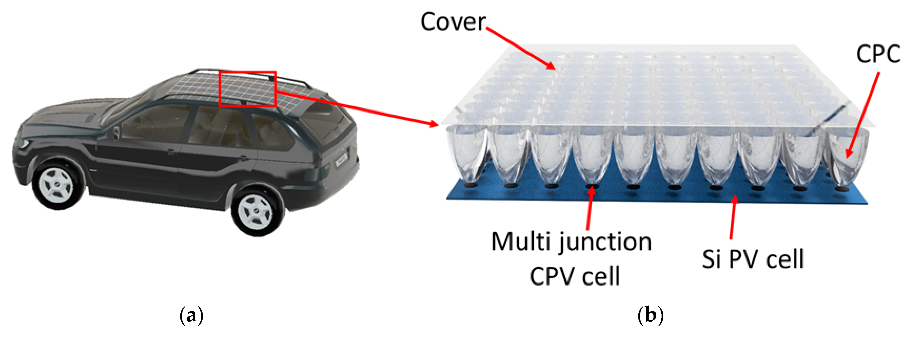
To solve this problem, the partially static CPV concept using a silicone lens array was applied, as introduced by Sato et al. [8]. This structure had a concentrator ratio of 3.5, with the highest optical efficiency of 50% on the CPV. Although there is great potential, the optical efficiency of 50% on a CPV is quite low and does not take full advantage of the efficiency of multilayer solar cells. Therefore, we propose a static CPV structure for electric vehicles as shown in Figure 1, with 78% optical efficiency on the CPV cells and a large half-acceptance angle of 47.8°, with a concentrator ratio of 4×. The overall photovoltaic efficiency of the module per day is 25%. Thus, when this structure is combined with high-efficiency solar cells, it can be a viable option for electric vehicles.
2. Concept of Static Concentrator Photovoltaics Module for Electric Vehicles
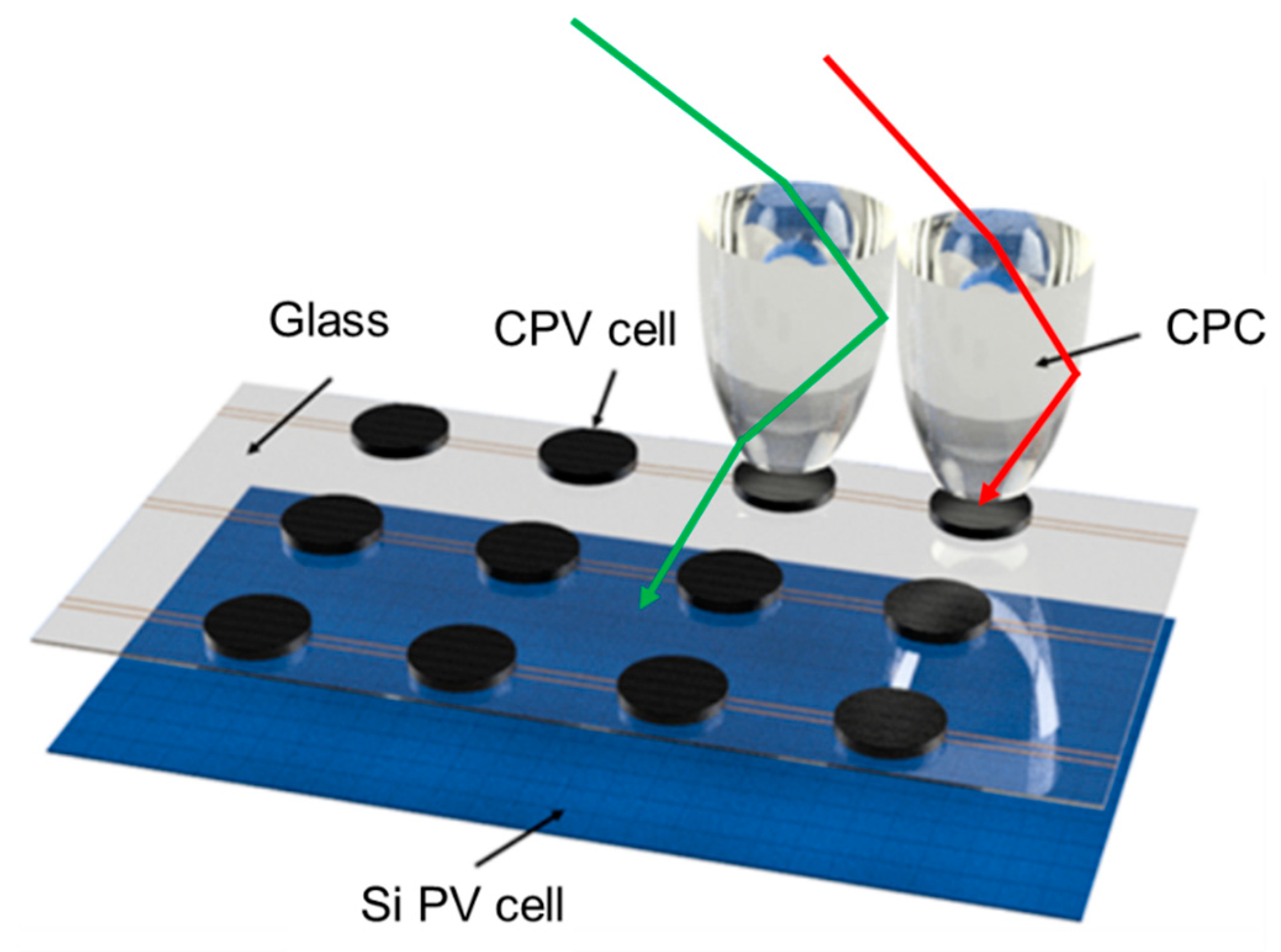
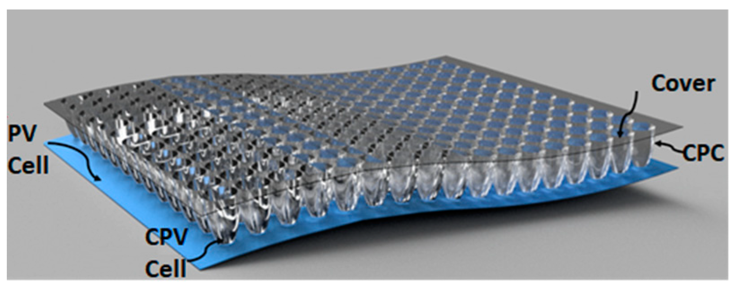
Conventional optical concentrators can be divided into two classes: static concentrators and active concentrators. Active concentrators are difficult to apply to automotive applications because vehicles require stability. Therefore, in this study, we introduce a new design method for a static CPV system that is completely based on a non-imaging compound parabolic concentrator (CPC) [9]. Figure 2 illustrates the design of a static CPV system for an automotive application with solid CPCs, three-junction solar cells (InGaP/GaInAs/Ge), and a Si cell panel. The CPCs encapsulate the three-junction cells atop the Si cell panel. Since the top surface shape of the CPC is circular, when CPCs cover the entire area of the roof, considering the area ratio between circle and square, the fill rate becomes about 80%. The module is covered by transparent glass. This system permits entry of diffused sunlight with a wide incidence angle range. Diffused light is collected by the Si solar cell. Direct sunlight with an incidence angle less than the acceptance angle of the CPC is captured by the CPC by total internal reflection (TIR) at the boundaries and absorbed in the multi-junction solar cells at the bottom. When the incident light exceeds the acceptance angle of the CPC, it leaks out of the CPC and is collected by the Si solar cell at the bottom.
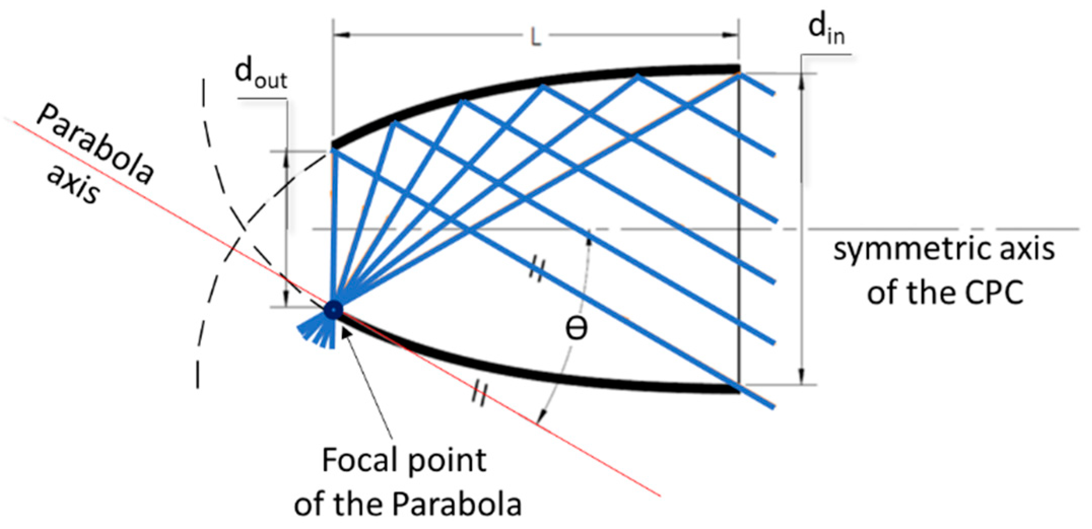
The compound parabolic concentrator (CPC) is a non-imaging optical device [10]. It is composed of two parabolic curved surfaces with their axes of symmetry tilted to create a specific acceptance angle through which divergent light is collected. The structure and design concept of CPC are shown in Figure 3. The axis of the parabolic is inclined at angles of θ with respect to the symmetric axis of the collector. Light rays that come to the (din) segment with an angle of incidence equal to θ will focus on the focal point of the parabolic, while rays with an angle of incidence less than θ will reach the (dout) segment.
The concentration ratio () of the CPC is the area ratio of the top surface (din) to the bottom surface of the CPC (dout), which is inversely proportional to the sine square of the half-acceptance angle for the standard symmetrical mirror CPC. The relationship between the and the half-acceptance angle for a three-dimensional compound parabolic concentrator is as follows:
where is the half-angle of the acceptance angle (of the larger aperture).
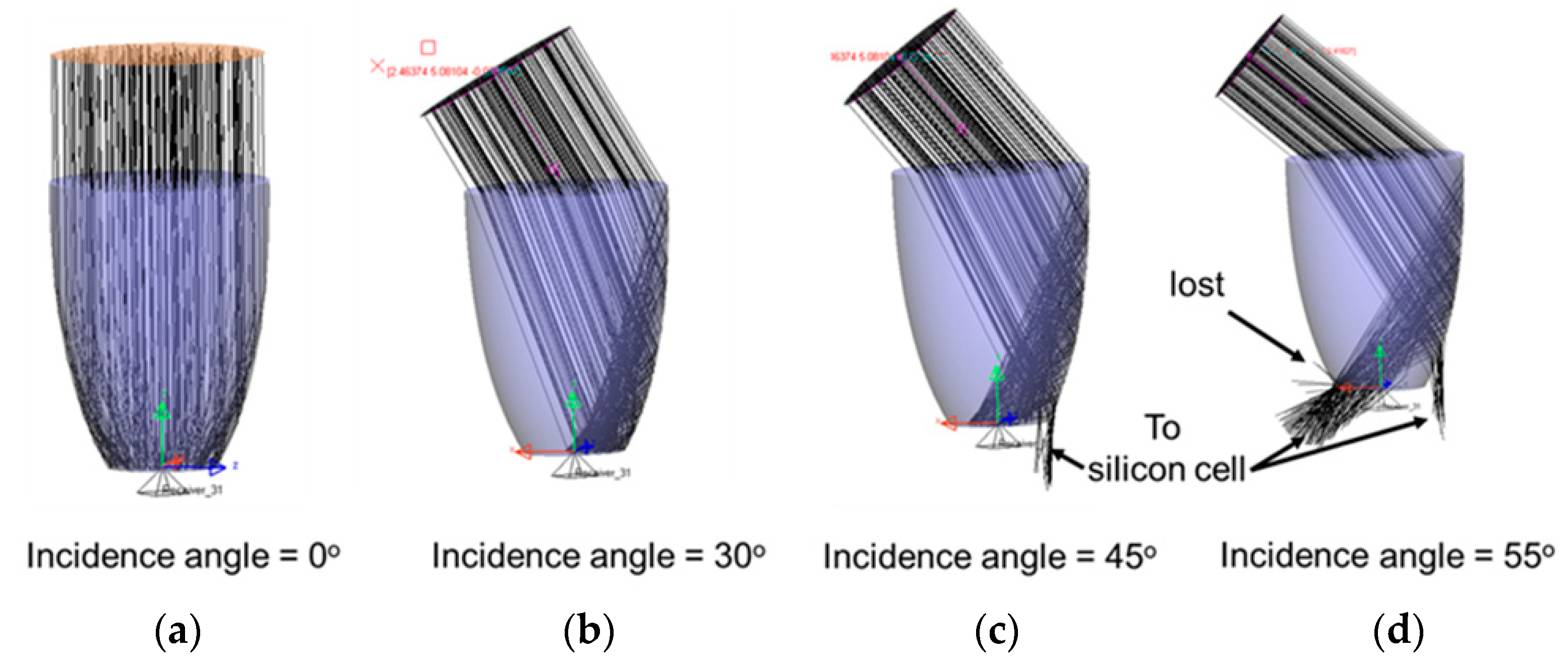
The corresponding geometrical concentration ratio is approximately 2.25 for the half-angle of the acceptance angle at 41.8°, 4 for 30°, and 6.25 for 23.5°. To reduce the CPV cell size, we can increase the geometrical concentration ratio [11], but the acceptance angle will be smaller. The use of a solid dielectric (acrylic) CPC could allow an extended acceptance angle without decreasing the geometrical concentration ratio based on Snell’s law. For example, when using a mirror CPC with a concentrator ratio of 4, if light enters the CPC at an incidence angle of 30°, it will reach the focal point, whereas light at an incidence angle less than 30° would go to the aperture. A solid CPC is made of dielectric material with the same configuration as a mirror CPC. The acceptance angle of a solid CPC will be widened due to refraction when light travels from the air to the CPC medium, while the internal acceptance angle of the CPC is the same as the mirror CPC due to total internal reflection. According to Snell’s law, as shown in Figure 4, a CPC made of acrylic with a refractive index of 1.49 will have an extended acceptance angle from 30° to 44.7°; therefore, light with an angle of incidence less than 44.7° can be refracted and then reach to the base of the CPC.
The use of a solid dielectric also helps to improve the overall efficiency of the system as light with an incidence angle greater than the acceptable angle does not escape but is captured by the underlying Si solar cell. When the incidence light exceeds the acceptance angle of the CPC, it is collected by the Si solar cell, as shown in Figure 4c,d. Specific optical performance is discussed in Section 3.
3. System Design and Simulation Results
3.1. System Design
We designed a system for performance simulation. The module size was 1 × 1 m. It had solid CPCs with different concentration ratios, and the same output size of 1 cm-diameter was chosen for comparison analysis. The 1 cm size was chosen because commercial multi-junction solar cells are available on the market in this size, which allowed us to make the actual system for further experiments. The selected concentrator ratios were CR = 2.25, CR = 4, and CR = 6.25. For different concentration ratios, the height and volume of the CPCs changed. They also changed according to the output aperture size. For a small aperture size, the number of total CPCs required for a 1 × 1 m module increased. Therefore, there was a trade-off between the size of the aperture for a higher concentration ratio and the number of CPCs for the module.
3.2. Optical Efficiency
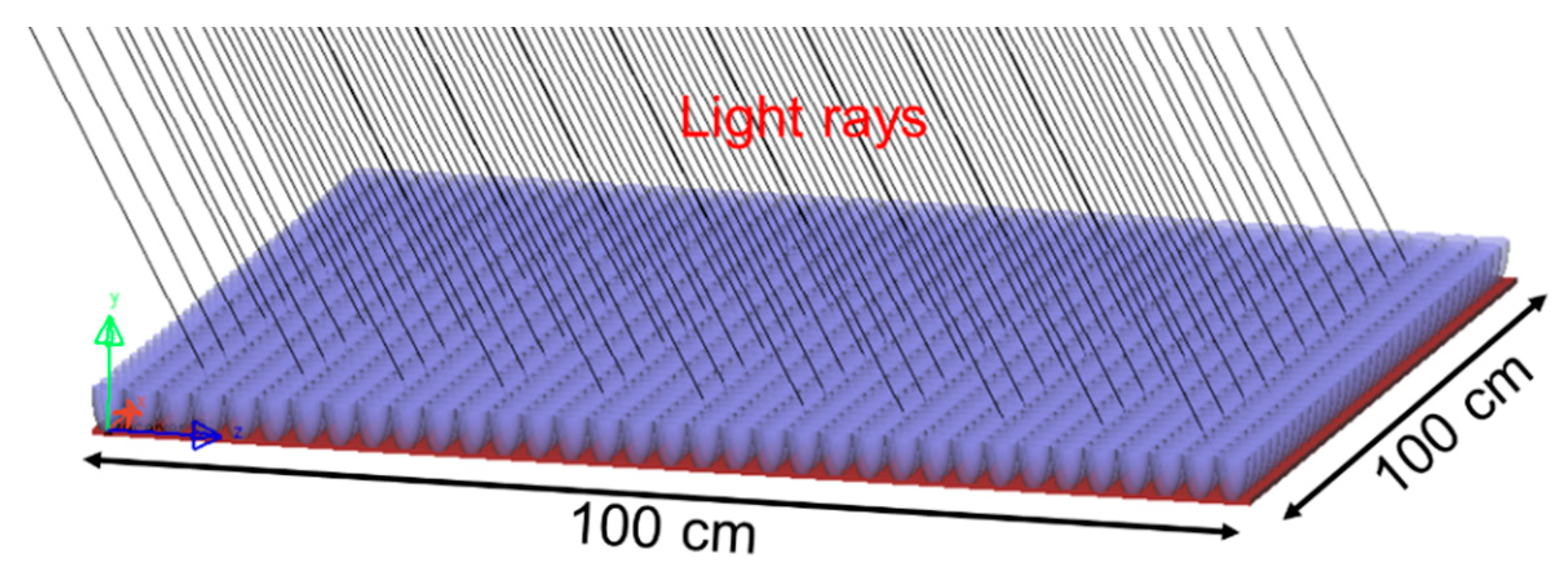
To validate the module design, we simulated the dependence of the optical performance on the angles of incidence. The optical efficiency of our designed module included the optical efficiency of multi-junction solar cells and PV cells calculated based on the ratio of light captured by each type of solar cell to the total incident light power. The simulation setup is shown in Figure 5. The incident light used had a collimation angle of 0.26° and a spectral range of 200–2500 nm, similar to that of direct sunlight [12]. The power of the light source was 1000 watts, and the area of the module was 1 × 1 m.
The optical efficiency of the module according to the incidence angle of direct sunlight was simulated using LightToolsTM software (Version 9.0, Synopsys, Inc., Mountain View, CA, USA). The angles of incident sunlight were changed from 0° to 70° to determine the light energy obtained by the multi-layered solar cells and the Si solar cell.
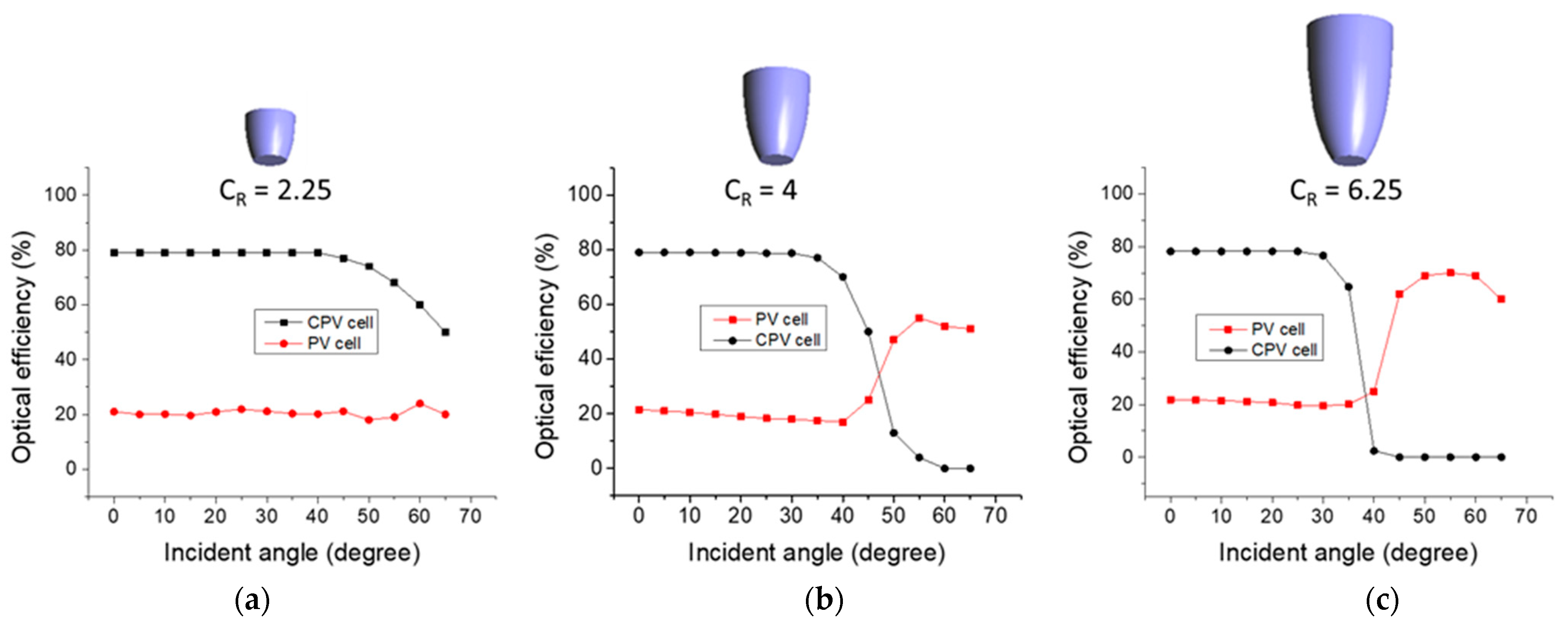
Figure 6 shows the simulation results of the dependence of optical performance of each module on the incidence angle, with incident angle ranging from 0° to 70°. The results showed that the simulation was consistent with the calculation of the acceptance angle of the CPC presented in Table 1. The optical efficiency of the CPC at incident angle of 0° was 78% and remained constant when the angle of incident light was less than the acceptance angle of the CPC. The optical efficiency of the PV panel remained constant at approximately 20% within the acceptance angle range of the CPC. The overall optical efficiency of the module was over 97% and only decreased when the incidence angle of the light was larger than the acceptance angle of the CPC.
The optical loss was due to material absorption and Fresnel loss. The optical efficiency of 78% achieved on the CPV cells can be explained as a filling ratio of CPC over the entire module area, which was 80%. When the incident light had an angle greater than the acceptance angle, it escaped from the CPC and went to the Si solar cell on the bottom. Small loss occurred because light rays with too large of an angle were reflected inside the CPC walls and exited the module. This was particularly significant when the incidence angle reached 60°.
3.3. System Performance and Discussion
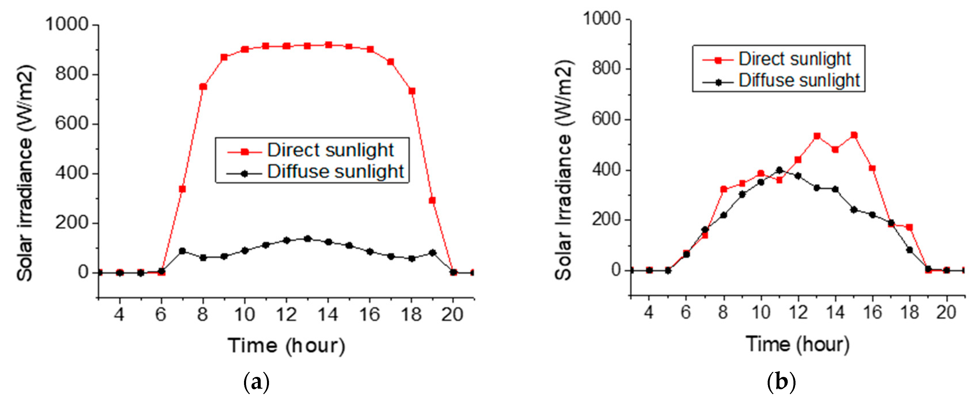
The daily power generation efficiencies of the three types of modules were evaluated using LightToolsTM software. In the simulation, two locations were selected: Phoenix (USA) and Seoul (Korea), representing regions with high direct normal irradiance (DNI) and low DNI, respectively. Solar radiation during the day at the two locations is shown in Figure 7. Phoenix has a high direct solar irradiance of up to 90% of total irradiance during the day and long sunshine hours, while Seoul represents the northern hemisphere climate with approximately 50% of direct irradiance. The total solar irradiance during the day is also less than in Phoenix. The contrast between climate conditions helped us evaluate the effectiveness of the design under different weather patterns.
Since the solar module for electric vehicles is a fixed panel, in this assessment, the power generation efficiency was compared with global horizontal irradiance (GHI), which is the total irradiance from the sun on the horizontal surface of the earth [13]. It is the sum of DNI (after accounting for the solar zenith angle of the sun (z)) and diffuse horizontal irradiance (DHI) [14]:
In Phoenix, the total solar irradiance (TSI) for 1 m2 measured perpendicular to the incoming sunlight is 11,450 Wh/day, and the GHI is 8248 Wh/day. In Seoul, the TSI is 7615 Wh/day, and the GHI is 6270 Wh/day for 1 m2. We simulated the amount of solar power coming to the static CPV modules in two different climates and calculated the power generation of the proposed system. The InGaP/InGaAs/Ge three-junction solar cells used in our system had a conversion efficiency of 35% [15]. The PV cell conversion efficiency was 20%. The power conversion efficiency of the proposed system can be calculated using the following equation:
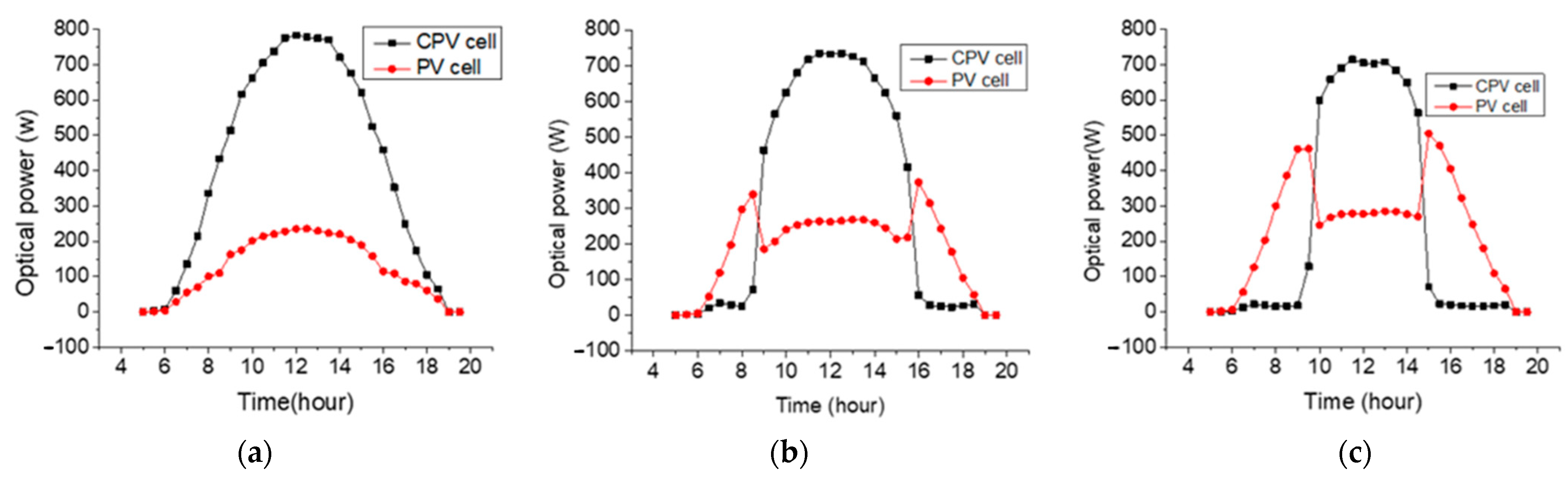
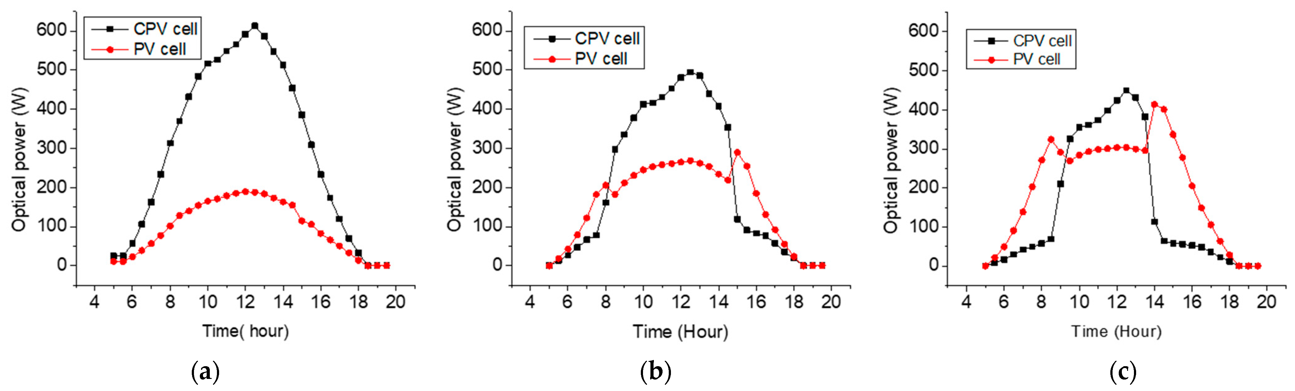
Figure 8 and Figure 9 show the optical powers of three different modules with a size of 1 × 1 m in Phoenix and Seoul. The total energy of each type of solar cell can be calculated by taking the integral of the output power over a day.
The results showed that, in most cases, the module with CR = 2.25 had the best effect. For the high DNI region, the peak of optical power obtained by the CPV cell had no significant difference. However, for the low DNI region, the peak of optical power obtained by the module with CR = 2.25 was 19% to 25% higher than that of the modules with CR = 4 and CR = 6.25. Different modules also had different effective working times. The module with CR = 6.25 with a low acceptance angle could effectively focus light on the CPV from 10:00 A.M. to 2:00 P.M. (4 h), while the module with CR = 4 and CR = 2.25 had an effective working time from 8:00 A.M. to 4:00 P.M. (8 h) and 6:00 A.M. to 6:00 P.M. (12 h). Thus, the module with CR = 4 had a time quite similar to the average commute time of 7.9 h/day [16] and was also the time with the highest solar radiation of the day in most cases [17]. This is also important information for car manufacturers to make a decision between the production cost and the efficiency of solar panel modules.
To evaluate the effectiveness of our system, we compared the performance of our CPV-based method with the PV method. The results are shown in Table 2. Table 2 shows the energy generation and daily module efficiency of each system per day in Phoenix and Seoul.
There were no significant differences in performance among the module types for the two locations. The lowest module efficiency was the module with CR = 6.25, with a value of 23%, and the largest was CR = 2.25, with an efficiency of over 30%. The efficiency results can be significantly greater when the module uses solar cells with higher efficiency, such as tandem solar cells with an efficiency of approximately 29% [18]. CPV cells with an efficiency of approximately 45% have been reported in recent studies [19].
An outstanding advantage of our design is the flexibility in the structure of the CPC. The CPCs are separate so that they can be flexibly arranged based on the shape of the car roof, as shown in Figure 10.
4. Conclusions
In this study, static CPV modules for car application were designed, simulated, and calculated. The structure of the module included CPCs, multi-junction solar cells, and a Si cell panel. The design can freely change the concentrator ratio of the CPC to suit different requirements of vehicle manufacturers. The results showed that the structure has high optical efficiency when sunlight has an angle of incidence smaller than that of CPCs, reaching 78% in all cases. The simulation results and the system’s converted energy calculation for different climatic conditions showed that the performance of the proposed system was significantly superior to that of the traditional PV-based method. With an ordinary electric vehicle with an average consumption of 132 Wh/km [20], a module with a size of 1 m2 can help the car run from 10 to 17 km/day, and the driving distance increases according to the size of the module. The results also showed that our design has consistent and reliable performance in different weather conditions and locations.
Further studies will focus on the flexibility of the static CPV module, and experiments are needed to verify the calculation and simulation results. However, current research has revealed the huge potential of this structure to be applied to electric vehicles.
Author Contributions
Original idea conceptualization, H.V.; simulation, H.V. and N.H.V.; formal analysis, N.H.V.; original draft—writing and preparation, H.V.; review and editing, N.H.V. and S.S.; project administration, S.S. All authors have read and agreed to the published version of the manuscript.
Funding
This work was supported by a National Research Foundation of Korea (NRF) grant funded by the Korean government (MSIT) (project number: 2021R1A2C1010879).
Institutional Review Board Statement
Not applicable.
Informed Consent Statement
Not applicable.
Data Availability Statement
The data that support the findings of this study are available upon request from the first author.
Conflicts of Interest
The authors declare no conflict of interest.
References
- Trends and Developments in Electric Vehicle Markets. Available online: https://www.iea.org/reports/global-ev-outlook-2021/trends-and-developments-in-electric-vehicle-markets (accessed on 30 July 2022).
- Lu, E.; Wang, N.; Zheng, W.; Wang, X.; Lei, X.; Zhu, Z.; Gong, Z. Data-Driven Electricity Price Risk Assessment for Spot Market. Int. Trans. Electr. Energy Syst. 2022, 9453879. [Google Scholar] [CrossRef]
- Yang, L.; Sun, Q.; Zhang, N.; Li, Y. Indirect Multi-Energy Transactions of Energy Internet with Deep Reinforcement Learning Approach. IEEE Trans. Power Syst. 2022, 37, 4067–4077. [Google Scholar] [CrossRef]
- Huyndai, E.V. Available online: https://www.pv-magazine.com/2019/07/25/hyundai-enters-the-solar-car-race-with-new-sonata/ (accessed on 7 February 2022).
- Average Car Travel Distance. Available online: https://www.numbeo.com/traffic/country_result.jsp?country=South+Korea (accessed on 7 February 2022).
- Lightyear Car. Available online: https://lightyear.one/ (accessed on 30 July 2021).
- Vu, N.H.; Pham, T.T.; Shin, S. Flat Concentrator Photovoltaic System for Automotive Applications. Sol. Energy 2019, 190, 246–254. [Google Scholar] [CrossRef]
- Sato, D.; Lee, K.H.; Araki, K.; Masuda, T.; Yamaguchi, M.; Yamada, N. Design of Low-Concentration Static III-V/Si Partial CPV Module with 27.3% Annual Efficiency for Car-Roof Application. Prog. Photovolt. Res. Appl. 2019, 27, 501–510. [Google Scholar] [CrossRef]
- Tian, M.; Su, Y.; Zheng, H.; Pei, G.; Li, G.; Riffat, S. A Review on the Recent Research Progress in the Compound Parabolic Concentrator (CPC) for Solar Energy Applications. Renew. Sustain. Energy Rev. 2018, 82, 1272–1296. [Google Scholar] [CrossRef]
- Bellos, E.; Korres, D.; Tzivanidis, C.; Antonopoulos, K.A. Design, Simulation and Optimization of a Compound Parabolic Collector. Sustain. Energy Technol. Assess. 2016, 16, 53–63. [Google Scholar] [CrossRef]
- Sellami, N.; Mallick, T.K. Optical Efficiency Study of PV Crossed Compound Parabolic Concentrator. Appl. Energy 2013, 102, 868–876. [Google Scholar] [CrossRef]
- Vu, H.; Tien, T.Q.; Park, J.; Cho, M.; Vu, N.H.; Shin, S. Waveguide Concentrator Photovoltaic with Spectral Splitting for Dual Land Use. Energies 2022, 15, 2217. [Google Scholar] [CrossRef]
- Page, J. The Role of Solar-Radiation Climatology in the Design of Photovoltaic Systems. Pract. Handb. Photovolt. 2012, 573–643. [Google Scholar] [CrossRef]
- Kalogirou, S.A. Solar Energy Engineering: Processes and Systems: Second Edition; Academic Press: Cambridge, MA, USA, 2014; pp. 1–819. [Google Scholar] [CrossRef]
- Fraunhofer Institute for Solar Energy Systems; PSE Projects GmbH Photovoltaics Report—2022—Fraunhofer ISE. 2022. Available online: https://www.ise.fraunhofer.de/conte%0Ant/dam/ise/d (accessed on 30 July 2022).
- American Time Use Survey Summary. Available online: https://www.bls.gov/news.release/atus.nr0.htm (accessed on 5 May 2022).
- Lisbona, E.F. Chapter IIA-2—Calibration, Testing, and Monitoring of Space Solar Cells. In Solar Cells, 2nd ed.; McEvoy, A., Castañer, L., Markvart, T., Eds.; Elsevier: Amsterdam, The Netherlands, 2013; pp. 501–529. ISBN 978-0-12-386964-7. [Google Scholar]
- Kamaraki, C.; Klug, M.T.; Green, T.; Miranda Perez, L.; Case, C. Perovskite/Silicon Tandem Photovoltaics: Technological Disruption without Business Disruption. Appl. Phys. Lett. 2021, 119, 070501. [Google Scholar] [CrossRef]
- Wiesenfarth, M.; Philipps, S.P.; Bett, A.W.; Horowitz, K.; Kurtz, S. Current Status of Concentrator Photovoltaic (CPV) Technology Version 1.3; National Renewable Energy Laboratory: Golden, CO, USA, 2017; pp. 1–27. [Google Scholar]
- Hyundai Kona Electric 64 KWh. Available online: https://ev-database.org/car/1204/Hyundai-Kona-Electric-64-kWh (accessed on 8 May 2022).
Figure 1.
The proposed static CPV module for an automotive application. (a) CPV module is installed on the car roof. (b) The detailed structure of the static CPV module.
Figure 1.
The proposed static CPV module for an automotive application. (a) CPV module is installed on the car roof. (b) The detailed structure of the static CPV module.

Figure 2.
Concept of the static concentrator photovoltaics module. The light (green) with an incidence angle greater than the acceptance angle of the CPC leaks out of the CPC and enters the Si cell. The light (red) with an incidence angle less than the acceptance angle of the CPC is captured by the CPC and enters the CPV cells.

Figure 3.
The structure and design concept of the CPC.

Figure 4.
A ray-tracing simulation model for the solid CPC with a concentration of 4 under different incidence angles. (a) Incidence angle = 0°, (b) incidence angle = 30°, (c) incidence angle = 45°, and (d) incidence angle = 55°.
Figure 4.
A ray-tracing simulation model for the solid CPC with a concentration of 4 under different incidence angles. (a) Incidence angle = 0°, (b) incidence angle = 30°, (c) incidence angle = 45°, and (d) incidence angle = 55°.

Figure 5.
A ray-tracing simulation setup for the solid CPC module under different incidence angles.

Figure 6.
Simulation results: the optical efficiencies as a function of incidence angles for different concentration ratios, (a) CR = 2.25, (b) CR = 4, and (c) CR = 6.25.
Figure 6.
Simulation results: the optical efficiencies as a function of incidence angles for different concentration ratios, (a) CR = 2.25, (b) CR = 4, and (c) CR = 6.25.

Figure 7.
Solar irradiance during a day in (a) Phoenix (USA) and (b) Seoul (Korea) for simulation.

Figure 8.
The optical powers of three different modules in Phoenix: (a) module with CR = 2.25, (b) module with CR = 4, and (c) module with CR = 6.25.
Figure 8.
The optical powers of three different modules in Phoenix: (a) module with CR = 2.25, (b) module with CR = 4, and (c) module with CR = 6.25.

Figure 9.
The optical powers of three different modules in Seoul: (a) module with CR = 2.25, (b) module with CR = 4, and (c) module with CR = 6.25.
Figure 9.
The optical powers of three different modules in Seoul: (a) module with CR = 2.25, (b) module with CR = 4, and (c) module with CR = 6.25.

Figure 10.
The flexible structure of the static CPV module for vehicle applications.


Table 1.
Main parameters of the static CPV module.
| Specifications | ||
|---|---|---|
| Module 1 | Concentration ratio | 2.25 |
| Module thickness | 14 mm | |
| Half-angle of acceptance | 62.3° | |
| Module 2 | Concentration ratio | 4 |
| Module thickness | 20 mm | |
| Half-angle of acceptance | 44.7° | |
| Module 3 | Concentration ratio | 6.25 |
| Module thickness | 25 mm | |
| Half-angle of acceptance | 35° | |
| General characteristics | Module size | 100 × 100 cm |
| CPC material | Acrylic | |
| CPV cell type | Triple-junction (GaInP/GaInAs/Ge) | |
| CPV cell diameter | 10 mm | |
| Efficiency of CPV cells | 35% | |
| Efficiency of PV cell | 20% | |
Table 2.
Performance comparison among three types of static CPV modules and a conventional PV panel.
Table 2.
Performance comparison among three types of static CPV modules and a conventional PV panel.
| Location | Parameter | CR = 2.25 | CR = 4 | CR = 6.25 | PV Panel |
|---|---|---|---|---|---|
| Solar cell | Three-junction cells with efficiency of 35% + Si cell with efficiency of 20% | Si cell with efficiency of 20% | |||
| Phoenix | Power generation by CPV cells | 2.14 kWh | 1.631 kWh | 1.24 kWh | 0 |
| Power generation by PV cells | 0.375 kWh | 0.568 kWh | 0.71 kWh | 1.65 kWh | |
| Daily module efficiency | 30.5% | 26.7% | 23.6% | 20% | |
| Seoul | Power generation by CPV cells | 1.57 kWh | 1.10 kWh | 1053 kWh | 0 |
| Power generation by PV cells | 0.295 kWh | 0.482 kWh | 0.44 kWh | 1.26 kWh | |
| Daily module efficiency | 29.75% | 25.15% | 23.9% | 20% | |
Publisher’s Note: MDPI stays neutral with regard to jurisdictional claims in published maps and institutional affiliations. |
© 2022 by the authors. Licensee MDPI, Basel, Switzerland. This article is an open access article distributed under the terms and conditions of the Creative Commons Attribution (CC BY) license (https://creativecommons.org/licenses/by/4.0/).
Share and Cite
MDPI and ACS Style
Vu, H.; Vu, N.H.; Shin, S. Static Concentrator Photovoltaics Module for Electric Vehicle Applications Based on Compound Parabolic Concentrator. Energies 2022, 15, 6951. https://0-doi-org.brum.beds.ac.uk/10.3390/en15196951
AMA Style
Vu H, Vu NH, Shin S. Static Concentrator Photovoltaics Module for Electric Vehicle Applications Based on Compound Parabolic Concentrator. Energies. 2022; 15(19):6951. https://0-doi-org.brum.beds.ac.uk/10.3390/en15196951
Chicago/Turabian StyleVu, Hoang, Ngoc Hai Vu, and Seoyong Shin. 2022. "Static Concentrator Photovoltaics Module for Electric Vehicle Applications Based on Compound Parabolic Concentrator" Energies 15, no. 19: 6951. https://0-doi-org.brum.beds.ac.uk/10.3390/en15196951
Note that from the first issue of 2016, this journal uses article numbers instead of page numbers. See further details here.