1. Introduction
Induction motors, particularly three-phase induction motors, play a key role in industry because of their advantages over other kinds of electrical machinery. Therefore, it is imperative that these motors operate in reliable, good conditions [
1]. In the literature, it has been reported that around 40% of induction motor faults are provoked by defects in the stator windings [
2]. These faults initiate as incipient short-circuit connections between coils in the same winding because of insulation degradation provoked by the thermal stress in which they operate. In some cases, the defect might expand as far as to cause short-circuit faults among feeding phases or between feeding phases and ground, with catastrophic results. Even though the winding insulation condition can be assessed offline, online determination techniques that do not intervene with induction motor working operations are preferred.
Nowadays, electric-machine condition monitoring has gained relevance because of its capability to reduce operational costs; therefore, new techniques have been proposed that are capable of performing an online, non-invasive analysis for detecting incipient faults while the machine is working [
3]. However, one of the crucial issues is the lack of a reliable mathematical model for describing a faulty motor. For instance, between-coil, short-circuit fault detection is performed by [
4] utilizing phase current magnitudes and fuzzy logic; however, using the motor phase currents without comprehending their dynamics will require a performance of several simulations, either through a computer-based model as a finite element, or a considerable number of experiments to retrieve enough information that can be useful for implementing the fuzzy logic system in charge of detecting the fault. In [
5], a methodology based on a fuzzy logic classifier is introduced for detecting stator faults in induction motors; however, since phase current magnitudes change depending on the motor load, an extensive database is required for the fuzzy logic system to be capable of detecting the fault. Using harmonic components in phase currents or in the stator current spatial vector is a common technique for detecting induction motor faults [
6]; however, these harmonic components have even been found in healthy motors because of inherent asymmetries in the machine. In [
7], short-circuit faults between coil turns in an induction motor are identified by utilizing multiple refence frameworks and an eccentricity indicator along with Park’s instantaneous space phasor module.
Electric current and vibration signals have been frequently used in industry for monitoring purposes. The analysis of these signals by themselves has been useful for detecting some specific faults. In [
8], electromechanical faults in a three-phase induction motor are detected by applying a methodology that combines electric current analysis with the processing of infrared images from thermographic cameras. Ref. [
9] introduces a fault diagnosis technique based on acoustic signals from a healthy motor, a motor with damaged bearings, and a motor with faulty bearings and a short circuit in one of its windings. A methodology based on the analysis of the startup electric current from an induction motor through the estimation of the signal homogeneity and its fourth statistical moments, which are used as inputs to an artificial neural network (ANN), is proposed in [
2] for identifying multiple faults. In [
10], an artificial intelligence-based technique is proposed that analyzes electric current measurements for detecting mechanical and electrical faults in three-phase induction motors. This technique makes use of an ANN for classifying the failure. In [
11], a convolutional ANN (CNN) is employed for detecting and classifying winding defects in an induction motor by examination of the raw stator current values at different damage levels.
In [
12], electric faults are detected in induction motors by means of computer modeling and an experimental validation analyzing electric faults in the stator, rotor bar fissure, and damaged short-circuited rings. Short-circuit faults are detected in [
13] through utilizing external magnetic field measurements from an induction motor. This method computes the energy of the detailed decomposition from the magnetic field discrete wavelet transform during the induction motor transient between its startup and standstill states. The wavelet transform provides a detailed analysis of unidimensional and bidimensional signals by performing a multilevel decomposition. An approach for detecting incipient short-circuit faults in the voltage source of inverter-fed induction motors is presented in [
14], taking into account that non-sinusoidal input voltage, along with short-circuit defects, induce harmonic components in the current signal, complicating the fault diagnosis based on the spectral analysis. A method for open-circuit diagnosis in power inverters is proposed in [
15] by phasor representation analysis of electric currents in the time domain; the methodology is compared against spectral analysis through fast Fourier transform and multiresolution examination utilizing wavelet transform. In [
16], a configuration for detecting multiple faults, such as between-coil short circuits and encoder defects, is introduced. The approach utilizes a structural representation of the system based on a dynamic mathematical model of the motor to analyze its constitution through matrix operations. A negative-sequence-current compensation is used in [
17] to increase the sensitivity and precision on detecting incipient faults on an induction motor under different disturbances since the negative-sequence current in a faulty motor contains characteristic components from the defects as well as from the disturbances.
In this work, phasor representation analysis is applied followed by a fuzzy logic classifier for detecting and classifying short-circuit faults in three-phase induction motors online. The novel introduced technique only requires three sensors to acquire the three-phase electric current power supply to perform a noninvasive condition monitoring; hence, the induction motor working condition is not modified. On the other hand, the proposed approach does not require computational demanding operations since it just performs the arithmetic differences from the RMS values of the line currents, followed by a fuzzy logic classifier based on simple linguistic if-then rules for detecting and classifying short-circuit faults in three-phase induction motors, outperforming previous approaches in the related literature. From experimentally obtained results, it is demonstrated that the proposed approach is capable of identifying and locating incipient and advanced short-circuit faults in the stator windings of an induction motor with high accuracy.
2. Short-Circuit Fault Diagnosis Scheme
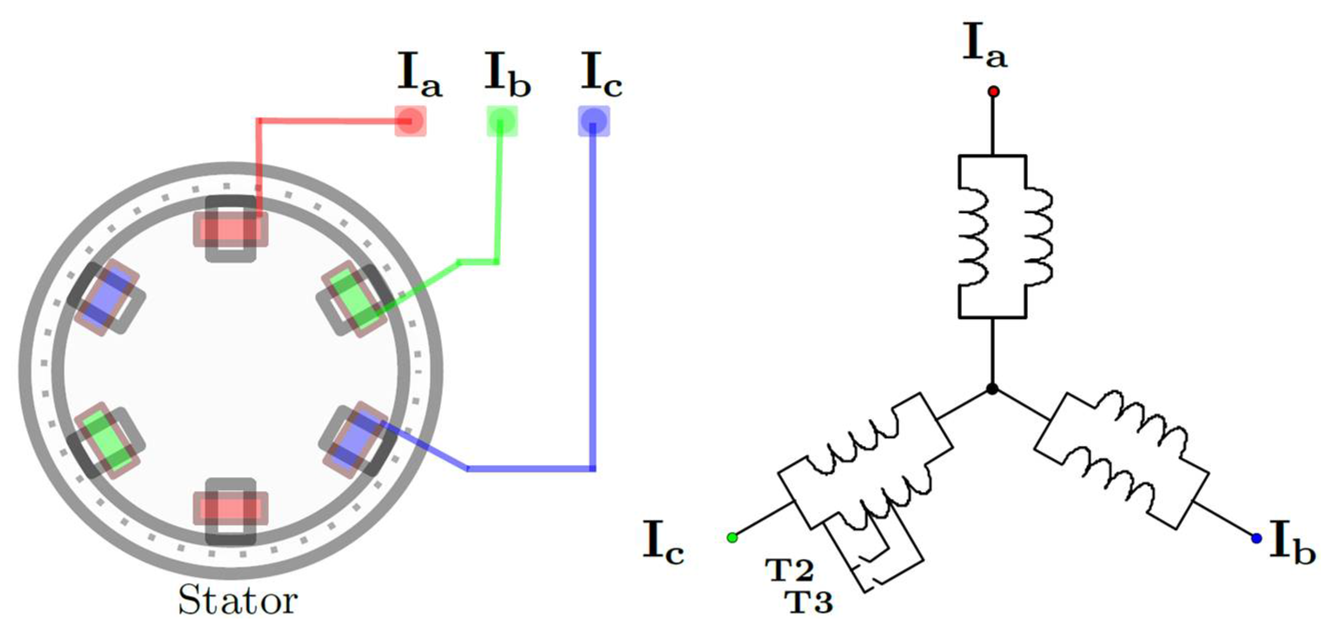
The proposed method for fault detection and recognition of short-circuited coils utilizes the phase and line current magnitudes of the induction motor since they show a particular behavior when a fault condition occurs. Phase and line currents exhibit asymmetries and specific patterns in their trajectories, which can be described and examined by means of phasor analysis.
Phasor representation analysis on the three-phase currents of an induction motor can be used for open-circuit and short-circuit fault diagnosis. The connection of the stator windings in a three-phase induction motor can be depicted as in
Figure 1.
Short-circuit faults in the stator windings of an induction motor can be categorized as:
- (i)
Partial-winding short circuit.
- (ii)
Full-winding short circuit.
A short-circuit fault in the full winding of one phase will stop the induction motor because of the protection system activation against over currents; hence, only incipient short-circuit faults are considered.
Figure 1 depicts a short-circuit defect beginning to form on the
Ic-phase inductance by closing tap T
2 or T
3, so that an unbalanced three-phase load is generated because the
Ic-phase inductance decreases as a consequence of the partial short-circuit fault; in other words, if a between-coils short circuit occurs, the winding impedance is reduced since two or more coils were connected in series before, and they will be made null after the short-circuit fault occurs. As consequence, the electric current through the
Ic-phase inductance is higher than the current going through any of the other two windings.
2.1. Short-Circuit Fault Analysis
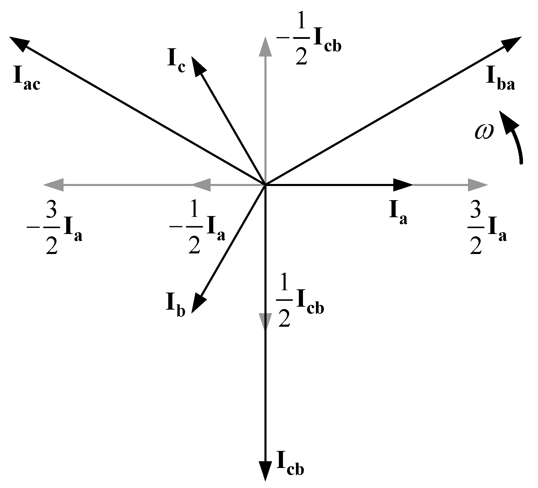
The short-circuit fault analysis is performed by considering the phasor representations of the stator phase and line currents in a healthy induction motor utilizing the per-unit system, as depicted in
Figure 2.
- (a)
Phasor representation of the phase currents.
- (b)
Phasor representation of the line currents.
Considering that any balanced three-phase current system in an induction motor stator must comply with
Ia +
Ib +
Ic = 0 because of the absence of a neutral grounded connection, it is possible to obtain phasor components or coordinates for each current in the induction motor stator in relation to the different reference systems; where, from
Figure 2, and Equations (1) and (2), it can be observed that a specific phase current is always perpendicular to a corresponding line current, establishing three reference systems:
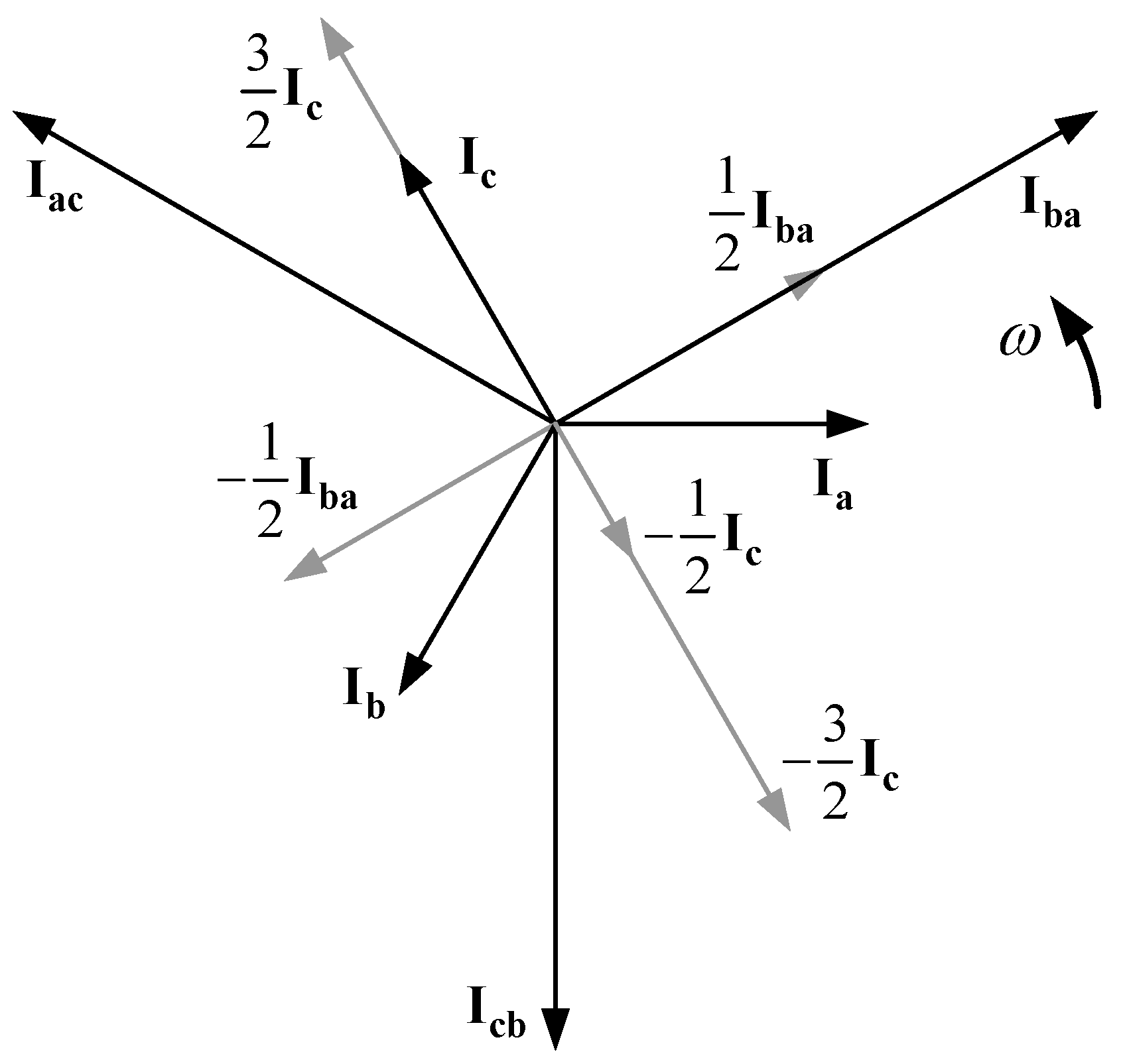
When a short-circuit fault occurs in the stator winding of phase
Ic, the most appropriate reference system to establish phase and line current behavior is
Ic ⊥
Iba.
Figure 3 shows the phasor components for the electric currents feeding an induction motor in good operational condition taking the
Ic − Iba reference system as basis.
The projections of the electric currents to the induction motor on the
Ic − Iba reference system directions are obtained as follows:
From (4), it can be noticed that when the magnitude of
Ic increases because of a short circuit on its corresponding winding,
Ia and
Ib magnitudes also rise but in different proportions. The augmentation of
Ia and
Ib magnitudes are due to the growing of their corresponding components in
Ic direction; however,
Iba remains without change.
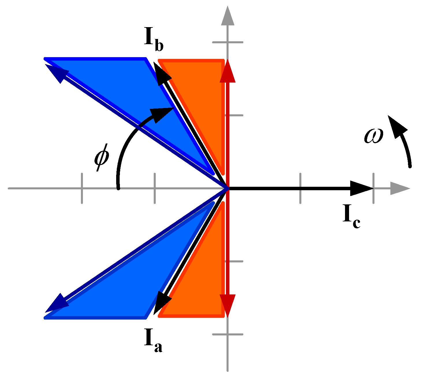
Figure 4 depicts the magnitude and phase angle (
ϕ) variations for currents
Ia and
Ib when either an open-circuit or a short-circuit fault occurs in the
Ic current phase of a three-phase power supply to an induction motor.
In
Figure 4, the red zone denotes the varying sectors for
Ia and
Ib magnitudes and phase angles when the
Ic amplitude drops until reaching zero (
Ic = 0). Under this condition,
Ia and
Ib go through these regions until setting on the opposite phase to each other, over the vertical axis; hence, phase current
Ia goes 30° forwards, whereas phase current
Ib moves 30° backwards. It is worth noticing that the magnitude and phase angle of line current
Iba remain unchanged, while
Ia and
Ib go through this red zone.
In
Figure 4, the blue region represents the fluctuating zone for
Ia and
Ib amplitudes and phase angles when the
Ic magnitude increases because of a short circuit. In this case,
Ia and
Ib move through this blue area from their starting value when there is not a failure; therefore, phase current
Ia falls behind 30°, whereas phase current
Ib advances 30°. It is important to notice that the magnitude and phase angle of line current
Icb do not change, while
Ia and
Ib move through this blue zone.
Even though the phasor representation analysis can detect variations in the magnitude and phase angle of the electric currents feeding an induction motor, the open- and short-circuit faults can be detected and distinguished through the fluctuation in the magnitude of line currents. However, if a line current does not exhibit any change in its magnitude, despite there being a short circuit in any of the phase currents, it is still possible to detect and isolate the fault.
2.2. Fuzzy Logic
As previously described, an artificial intelligence technique that can take advantage of phase and line current behavior to identify short-circuit faults in an induction motor winding is fuzzy logic since by knowing the current asymmetries, only three comparisons of the current magnitudes are required for detecting and locating the fault through a Mamdani type inference system. In this work, simple if-then rules are used for performing these comparisons, which assume the following structure:
where, A and B are linguistic values defined by fuzzy sets in the universes of discourse X and Y, respectively. The sentence “
x is A” is called the premise or antecedent, whereas “
y is B” is known as the conclusion or consequent [
18]. The fuzzy rules are defined by considering the RMS values of line currents
Icb,
Iac, and
Iba to the induction motor, which are obtained as:
where
Ia,
Ib, and
Ic are the phase currents.
The RMS values of the line currents and the operations defined in (6) are used for obtaining the linguistic rules in (7) to detect and classify short-circuit faults.
3. Experimental Results
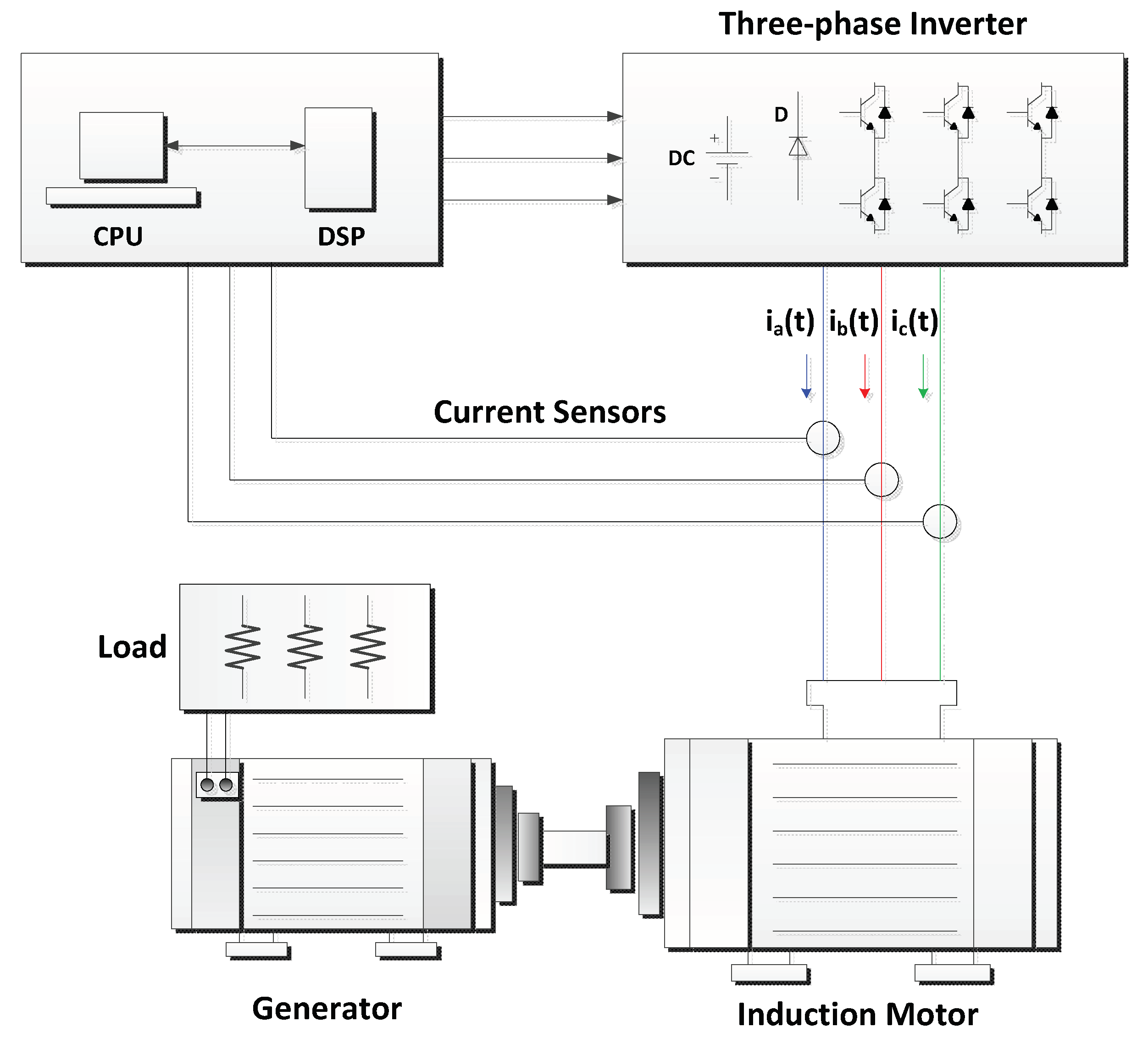
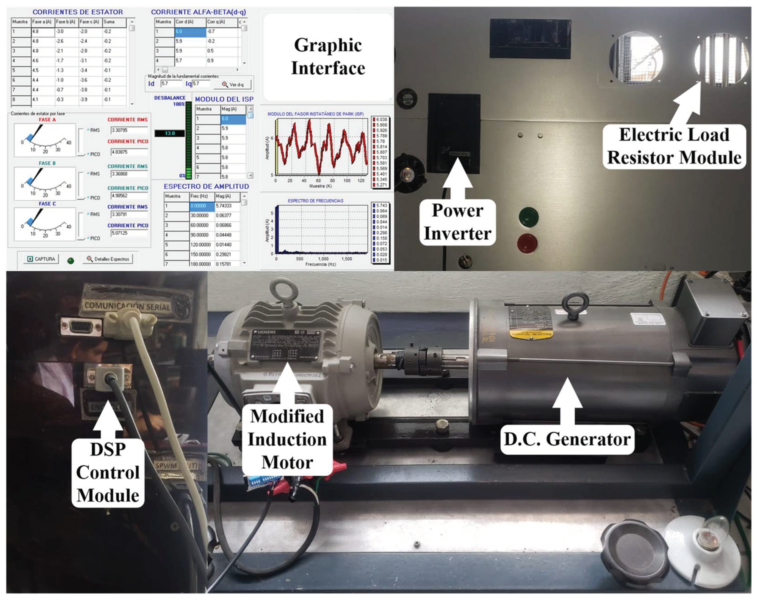
Figure 5 depicts the configuration scheme of the system utilized for experimentation, and
Figure 6 shows the test bench constructed for performing the experiments, which consist of a 3 Hp, 220/440 V at 60 Hz three-phase induction motor from SIEMENS rotating at 1800 rpm with 4-ploles in a double-star connection. The induction motor is connected to the power supply through a three-phase inverter that controls the provided voltage and frequency utilizing a personal computer and a data acquisition system DSP TMS320F28335 from Texas Instruments with a sampling rate of 3.840 kHz. The winding of one input phase is modified so that 5% and 12% short-circuit faults are replicated. A common generator that transfers voltage to a resistive load is coupled to the induction motor as a load.
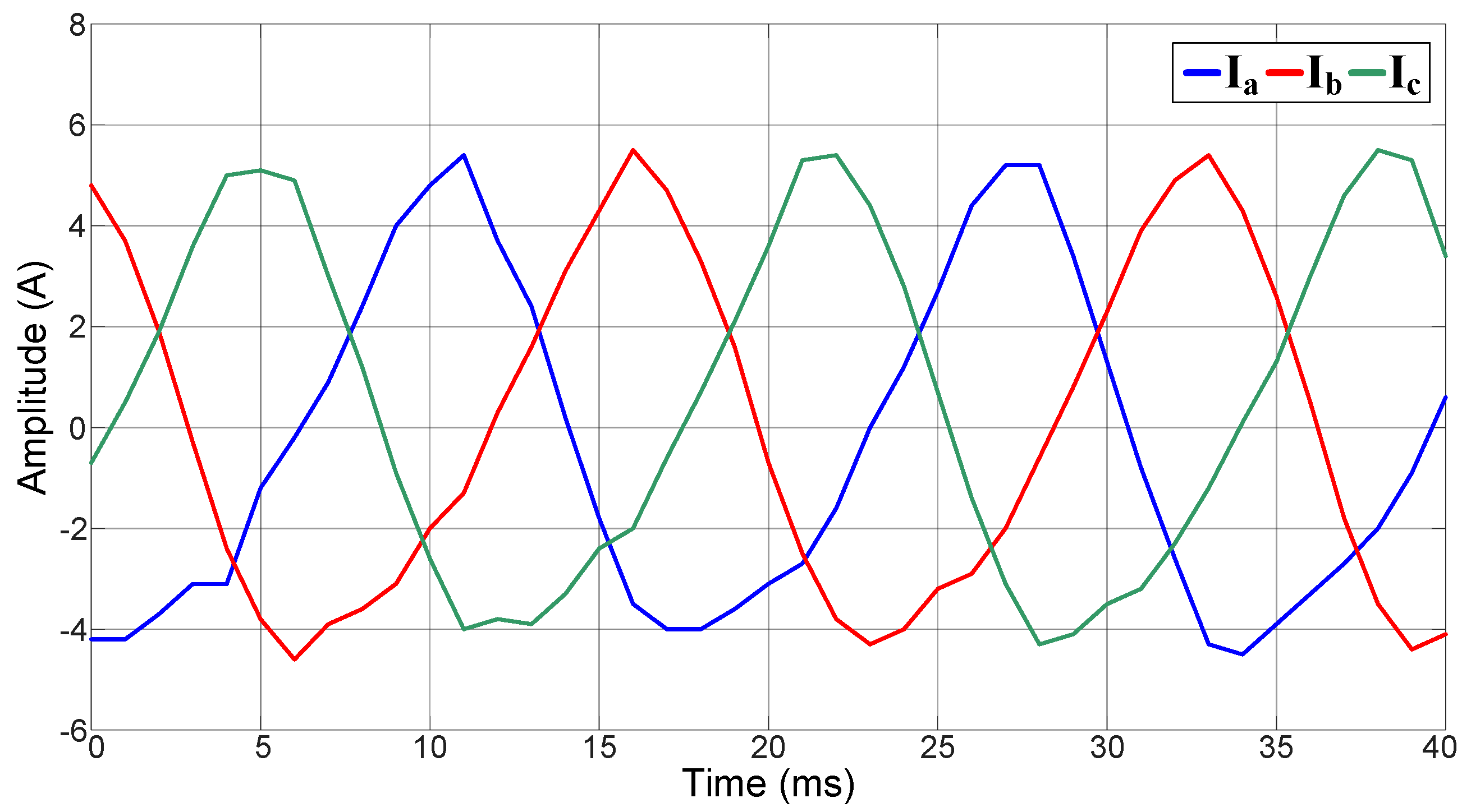
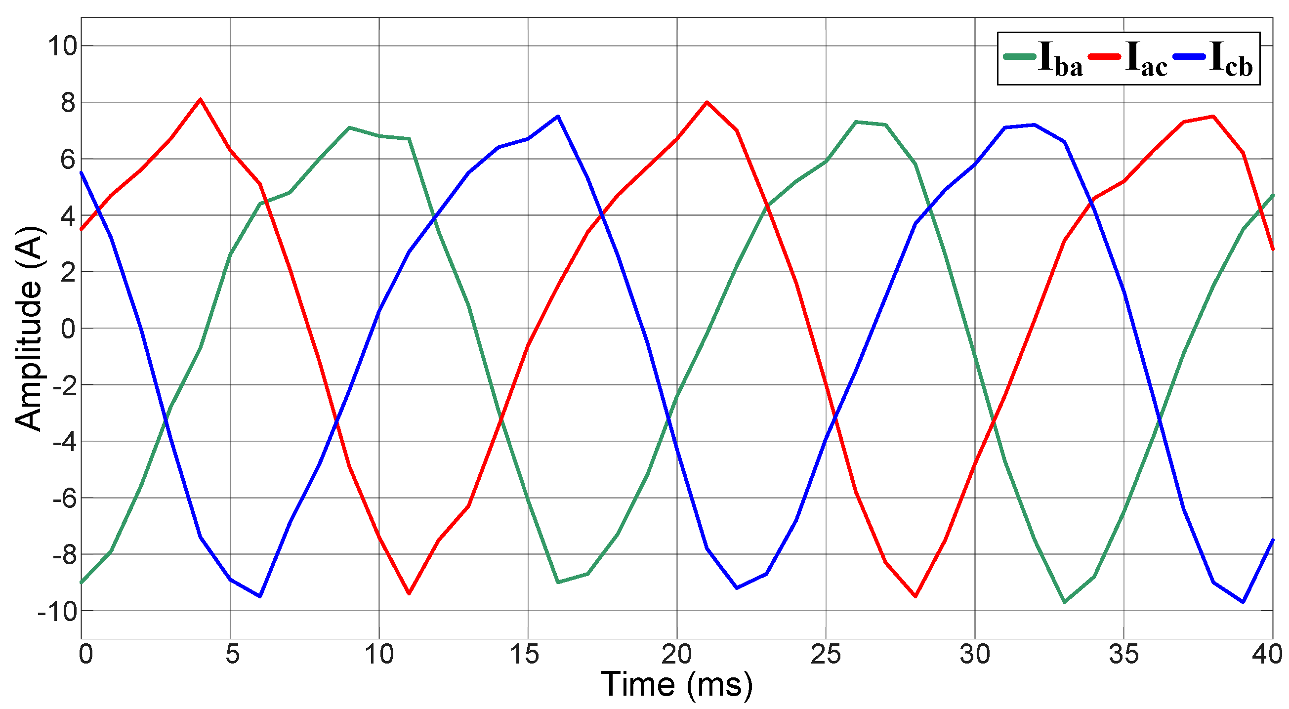
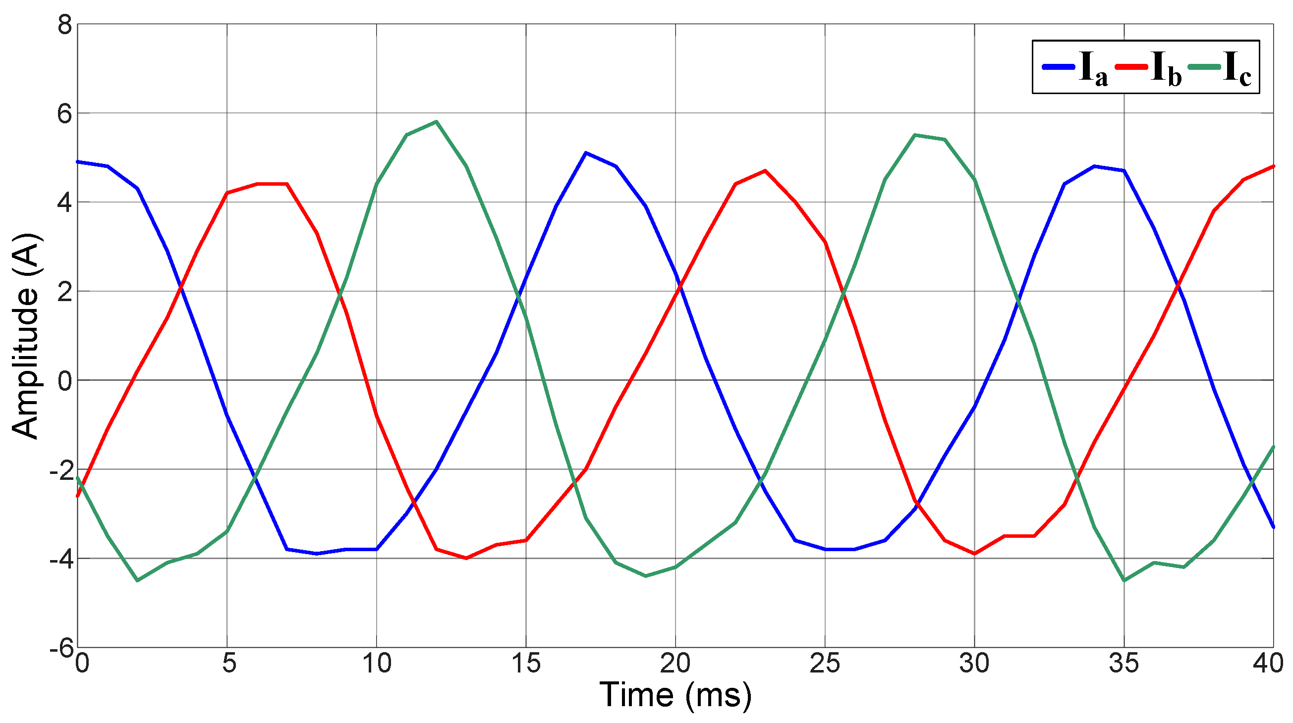
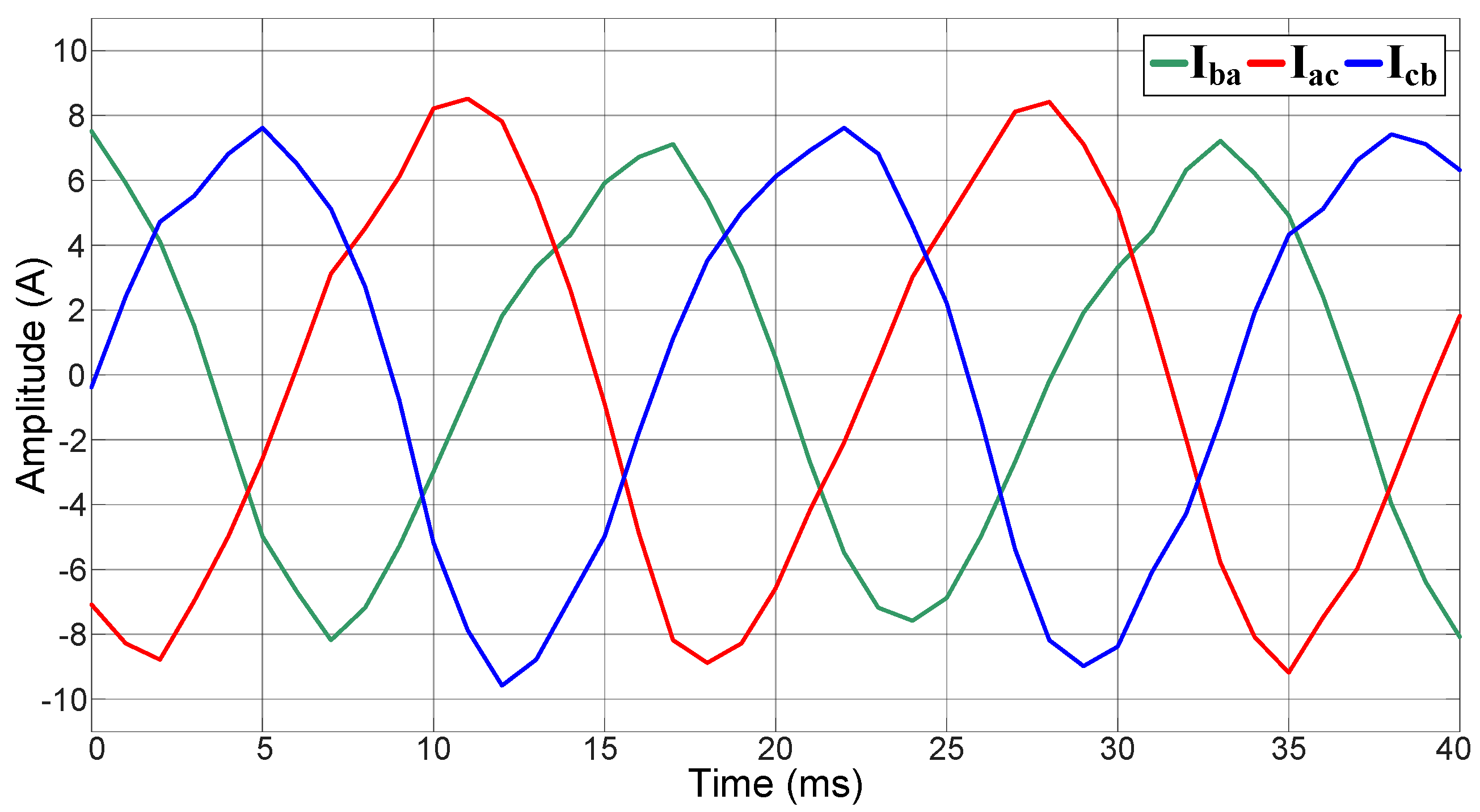
The phase and line currents of the motor in healthy condition are obtained and depicted in
Figure 7 and
Figure 8, respectively. From these figures, it can be observed that the three current amplitudes, either the phase or the line currents, have the same magnitude because there is not any short-circuit fault in the stator windings.
The unbalanced phase and line currents from an induction motor with a 5% short-circuit fault in the phase-C stator winding using the tap T
2 of the start connection is switched on, as depicted in
Figure 1.
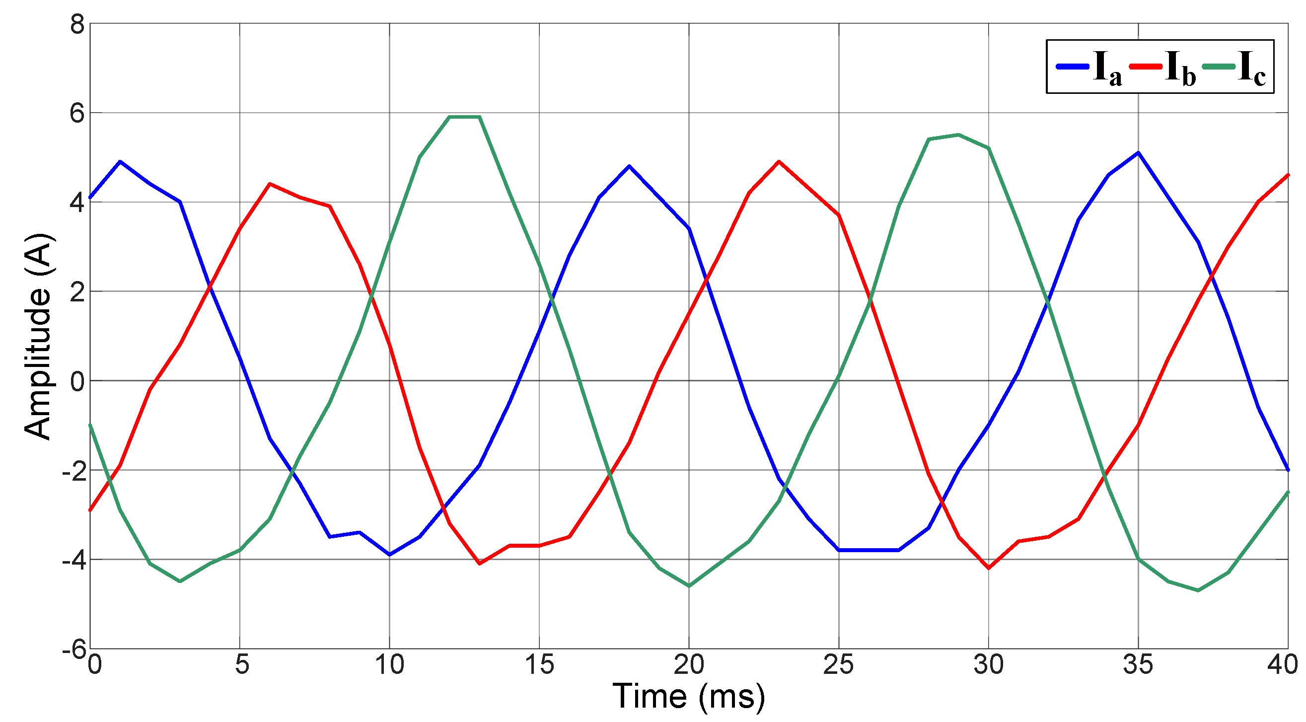
The greatest increment in the phase-C current
Ic is shown in
Figure 9. This magnitude growth is due to the short-circuit fault among the coils of the corresponding stator windings in the induction motor. It can be observed that the magnitude increases on each phase and current
Ia and
Ib are around half of that one on
Ic because of the short-circuit fault, as it can be computed directly by utilizing (4).
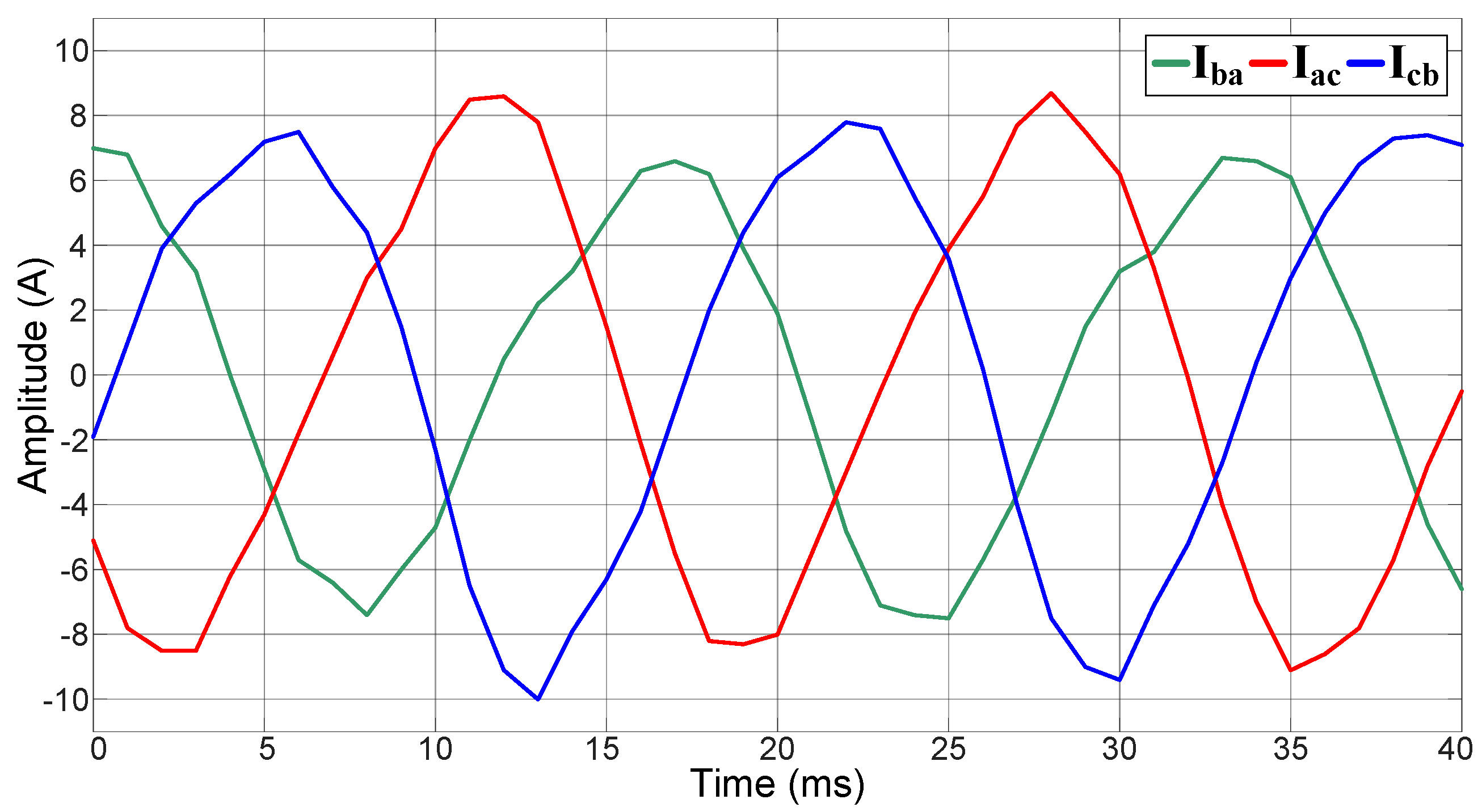
In
Figure 10, it can be observed that line current
Iba remains constant since it is perpendicular to phase current
Ic where the short-circuit fault occurs. In other words, line current
Iba and phase current
Ic are linearly independent, whereas line currents
Iac and
Icb are dependent on the
Ic current of the faulty stator winding; hence,
Iac and
Icb experience some variations. From these dependence and independence relations among corresponding line and phase currents, it is possible to detect and locate short-circuit faults in the stator windings of the induction motor.
Figure 11 shows a higher escalation of the current
Ic amplitude since more coils are short-circuited by activating the tap T
3 in the start connection. The number of short-circuited coils is equivalent to 12% of the winding. The fluctuations in the phase current amplitudes can be determined by (4).
In
Figure 12, it can be observed once more that the amplitude of line current
Iba remains without change, which can be deduced analytically by (4), whereas the magnitude of line currents
Iac and
Icb have more amplitude variations.
Table 1 and
Table 2 show phase and line current behavior, respectively, before and after a short-circuit fault occurs in the phase
Ic stator winding of the induction motor. From
Table 1, it can be noticed how the magnitude of the phase current
Ic amplitude significantly increases regarding the amplitude magnitude of phase currents
Ia and
Ib, whose corresponding windings are in a healthy condition. Because of the faulty condition in phase
Ic, the percentage of short-circuited coils also increases. Meanwhile, in
Table 2, it can be observed how the magnitude of the line current
Iba amplitude remains practically unchanged.
Hence, from what has been stated before, it is clear that knowing the phase and line currents’ behavior, before and after a short-circuit fault occurs in any stator winding of a three-phase induction motor, it will be possible to identify and classify the occurrence of a short-circuit fault by performing the arithmetic operations defined in (6) and applying the linguistic rules in (7).
Table 3 displays the differences
r1,
r2, and
r3 obtained from the corresponding RMS values from line currents
Icb,
Iac, and
Iba, applying (6) to five different experiments conducted on a healthy motor. By employing the fuzzy logic linguistic rules defined in (7), it is determined that the condition
r1 ≈
r2 ≈
r3 ≈ 0 is satisfied; therefore, it can be resolved that the three-phase induction motor under examination is healthy.
Results in
Table 3 can be verified graphically by the line current waveforms depicted in
Figure 8, where the magnitudes of the three-line current amplitudes are relatively the same, corroborating through the fuzzy rule
r1 ≈
r2 ≈
r3 ≈ 0 that the stator windings in the induction motor are healthy.
The behavior of line currents changes by inducing a short-circuit fault in the stator winding corresponding to phase
Ic, so that, two-line currents show variations on the magnitude of their amplitudes, whereas the magnitude of the third line current amplitude remains invariable, as depicted in
Figure 10 and
Figure 12. From this, the corresponding linguistic fuzzy logic rule that identifies and classifies the fault (
r1 ≈ 0) can be corroborated as described arithmetically in
Table 4 for 5%, and
Table 5 for 12% in the coils in the stator winding corresponding to the short-circuited phase
Ic.
4. Discussion
A statistical analysis is performed by computing the mean (
μ) and standard deviation (
σ) of the line current differences
r1,
r2, and
r3 for a healthy motor, as shown in
Table 3; a motor with 5% of the coils in its phase
Ic winding short-circuited, as shown in
Table 4; and a motor with 12% of the coils in its phase
Ic winding short-circuited, as shown in
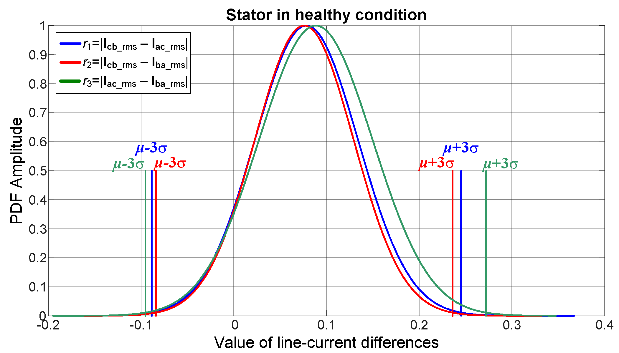
Table 5. An empirical three-sigma (3
σ) rule, which ensures a certainty of at least 99.7%, is used on the arithmetic line current differences
r1,
r2, and
r3 to verify the effectiveness of the proposed method. From this 3
σ analysis, it can be observed that for all cases, the arithmetic line current differences
r2 and
r3 vary between the thresholds defined by the corresponding mean value plus/minus three times the related standard deviation (
σ), whereas the line current difference
r1 essentially remains without change for the three cases: (1) a healthy motor, (2) a motor with 5% and (3) a motor with 12% of the coils in its phase
Ic winding short-circuited, as depicted in
Figure 13,
Figure 14 and
Figure 15, respectively, when the failure is located in the stator winding corresponding to phase
Ic of an induction motor.
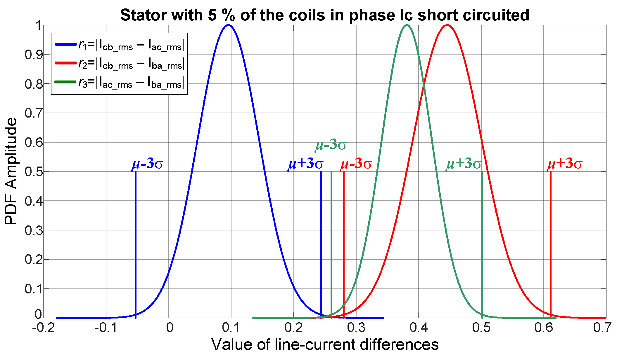
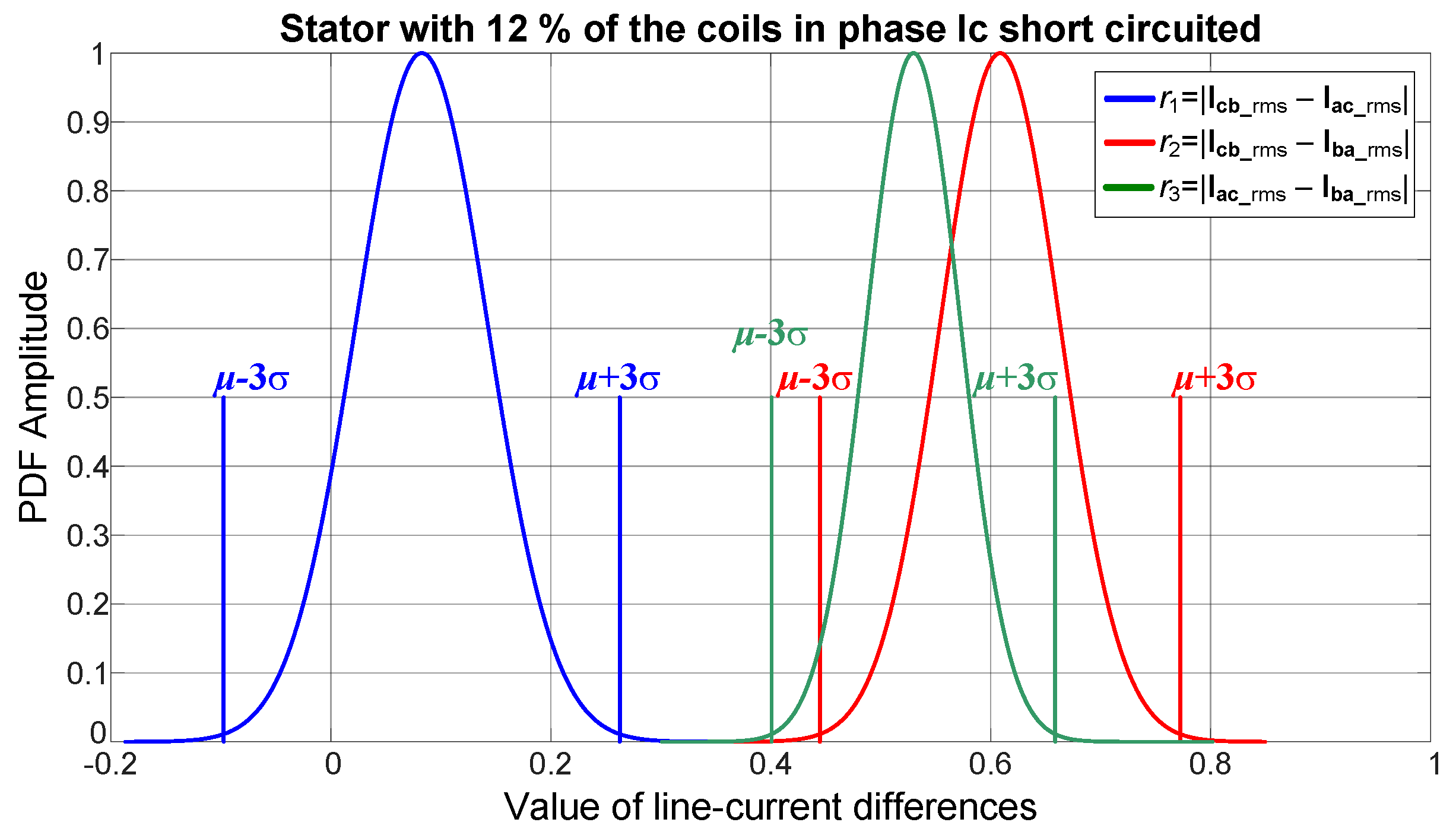
From
Figure 13, it can be observed that for a healthy motor, the three line current differences
r1,
r2 and
r3 have very similar probability density functions; however, as the short-circuit fault appears and increases from 5% to 12% in the coils in the phase
Ic winding, the mean (
μ) and standard deviation (
σ) of the line current differences
r2 and
r3 change and separate from the mean (
μ) and standard deviation (
σ) of the line current difference
r1, as depicted in
Figure 14 and
Figure 15, endorsing the utilization of the linguistic fuzzy rules defined in (7) for detecting and locating the short-circuit fault automatically.
5. Conclusions
Around 40% of induction motor faults are provoked by defects in the stator windings. These defects may provoke short circuits among feeding phases with catastrophic results. Most proposed techniques in the literature assess the winding insulation condition offline utilizing complex analysis methods; however, an online diagnostic technique that does not interfere with the induction motor’s working operation would be preferred. Therefore, in this work, a short-circuit fault detection approach is proposed which does not require the motor to stop to diagnose its operational condition. The proposed procedure utilizes a phasor representation analysis that consists of computing the arithmetic differences from the RMS values of the line currents, followed by a fuzzy logic classifier based on simple linguistic if-then rules to detect and classify short-circuit faults in three-phase induction motors. From the analysis of the obtained results and the 3σ-rule examination, it is demonstrated that the proposed straightforward technique allows an online implementation since it demands low computational resources and, knowing the behavior of phase and line currents as well as their corresponding magnitudes, the presence of a short-circuit fault and the feeding phase where it occurs can be determined through simple linguistic if-then rules, allowing diagnosis of the induction motor’s operational condition without interfering with its working operation. Furthermore, the proposed method is highly reliable under distinct operating scenarios since, for the case of induction motors fed through a variable speed drive (VSD), variations in the power supply amplitude or phase will be lessened through the inherent rectifying process; when the induction motors are fed directly from the power supply, variations in the amplitude or the harmonic contents of the power supply will be compensated due to Ia + Ib + Ic = 0 for any current three-phase balanced system with a neutral ground connection absent.
Future work will focus on performing a thorough analysis on how the proposed technique effectiveness for detecting short-circuit faults is affected when the induction motor load varies continuously. On the other hand, the introduced approach will be assessed for identifying open-circuit faults in the stator windings in induction motors, as well as for detecting short- and open-circuit faults in the windings of brushless dc (BLDC) motors.


 ,
, 


